

Operating Instructions
Photometer 5010
V5+
ROBERT RIELE GmbH & Co KG
Software Version 5.13
Documentation Version 01.2010

5010e_513.doc / 22.01.10
SYMBOLS
The packaging material, the type plate on the instrument and the manual may contain the following symbols or
abbreviations:
Manufactured by:
This product fulfills the requirements of Directive 98/79/EC on
in vitro diagnostic medical devices.
In vitro diagnostic medical device
IP XO
REF
SN
Caution (refer to accompanying documents)!
Please refer to safety-related notes in the manual accompanying this device.
Please consult instructions for use
Symbol for the marking of important information for appropriate handling of the device
Description of the technical specifications according DIN 58 960 part 4
Biohazard
Samples containing material of human origin must be treated as potentially infectious.
The relevant laboratory guidelines on safe use must be observed.
Symbol for the marking of electrical and electronics devices according to § 7 ElektroG
No special protection against penetrating moisture (IP = International Protection)
Order number
Serial number
INSTRUMENT APPROVALS
The Photometer 5010 meets the requirement stated in Directive 98/79/EC of the European Parliament and the
Council of the European Union (EU) on in vitro diagnostic medical devices. Furthermore, the Photometer 5010
is manufactured according to the special safety requirements for IVD medical devices stated in DIN EN 61010,
testified by TÜV Rheinland Group.
The Photometer 5010 fulfils the EMC immunity requirements for laboratory use equipment according to the
EMC standard EN 61326.
ROBERT RIELE GmbH & Co KG Page 2 GENERAL NOTES

5010e_513.doc / 22.01.10
SAFETY INFORMATION
Operator qualification
Only appropriately trained operators are qualified to operate the device.
Environmental conditions
The Photometer 5010 is approved for indoor use only.
For further environmental conditions see chapter 10.1.
Patient ambience
The Photometer 5010 may not be used in the patient ambience.
Electrical Safety
This device was examined and left the factory in perfect technical condition. To preserve this and protect safe
and faultless operation, the operator must follow the orders and remarks of this operating manual.
Connect the device to grounded power outlets only. All peripheral devices that are connected to the Photometer
5010 must comply with safety standard EN 60950. Before connecting read the documentation of the peripheral
devices.
Opening covers or removing parts of the instrument, except where this can be achieved manually without the
use of any tool, may expose voltage-carrying components. Connectors can be live, too. Never try to maintain or
repair an open instrument which is carrying voltage.
Repairs at the device including replacement of the Lithium battery may be carried out only by authorized
specialist staff. Through improper repairs the warranty extinguishes, and the operator can be heavily jeopardized.
If suspected the device can no longer be operated safely, turn it off and take steps to ensure that no one will
subsequently attempt to use it.
Electromagnetic waves
Devices that emit electromagnetic waves may affect measured data, or cause the Photometer 5010 to malfunction. Do not operate the following devices in the same room where the Photometer 5010 is installed: mobile
phone, transceiver, cordless phone, and other electrical devices that generate electromagnetic waves.
Reagents
Regarding reagents follow the safety as well as the operating instructions of the manufacturers.
Pay attention to the currently valid German “Gefahrstoffverordnung” (GefStoffV)!
Biological safety
Liquid waste is potentially biologically hazardous. Always wear gloves if handling those materials. Do not touch
parts of the device other than those specified. Consult the laboratory protocol for handling biohazardous
materials.
Pay attention to the currently valid German “Biostoffverordnung” (BioStoffV)!
Spillings and cleaning
If a sample is spilled on the device, wipe up immediately and apply disinfectant.
Waste
Handle liquid waste properly, according to legislation on water pollution, and on the treatment of drainage and
waste matter.
ROBERT RIELE GmbH & Co KG Page 3 GENERAL NOTES

5010e_513.doc / 22.01.10
MANUFACTURER’S WARRANTY
ROBERT RIELE GmbH & Co KG warrants Photometer 5010 against defects in material and workmanship.
For further information contact the local distributor.
WASTE MANAGEMENT NOTE
At the end of the life or utilization time the device and the accessories can be given back to the manufacturer
with costs for an environmental waste disposal. The previous professional decontamination has to be proved
with a certificate.
Address of the manufacturer:
ROBERT RIELE GmbH & Co KG
Kurfuerstenstrasse 75-79
13467 BERLIN
GERMANY
Phone: +49 (0)30 404 40 87
Fax: +49 (0)30 404 05 29
E-mail:
www.riele.de
info@riele.de
QUALITY MANAGEMENT SYSTEM
ROBERT RIELE GmbH & Co KG maintains a quality management system according to EN ISO 9001:2008, and
EN ISO 13485:2003+AC:2007 certified by TÜV Rheinland Product Safety GmbH.
ROBERT RIELE GmbH & Co KG Page 4 GENERAL NOTES

5010e_513.doc / 22.01.10
CONTENTS
1 INTRODUCTION TO PHOTOMETER 5010................................................7
2 INSTALLATION .............................................................................................8
2.1 DELIVERY ........................................................................................................................................ 8
2.2 PREPARATION FOR INSTALLATION............................................................................................ 8
2.3 INSTALLATION................................................................................................................................. 8
2.4 LOADING PRINTER PAPER .......................................................................................................... 9
3 OPERATING ELEMENTS...........................................................................10
3.1 FRONT.............................................................................................................................................10
3.2 BACK ...............................................................................................................................................10
3.3 TOUCHSCREEN..............................................................................................................................11
3.4 WORKING AREA............................................................................................................................11
3.5 CUVETTES AND CUVETTE ADAPTOR.......................................................................................12
3.5.1 Changing cuvette adaptor........................................................................................................12
3.5.2 Working with original flow-through system...............................................................................12
3.5.3 Working with standard cuvettes ...............................................................................................13
3.5.4 Working with discrete flow-through cuvette..............................................................................13
4 PROGRAM SELECTION.............................................................................14
4.1 Measurement with programmed methods ........................................................................................14
4.2 Measurement with basic methods ....................................................................................................15
4.3 Method editor ...................................................................................................................................15
4.4 Utility programs ................................................................................................................................16
4.5 Lamp protection [LAMP]...................................................................................................................16
4.6 Line feed [LF] ...................................................................................................................................16
5 CALCULATION PROCEDURES.................................................................17
5.1 GENERAL NOTES..........................................................................................................................17
5.1.1 Fundamental to the handling ... ...............................................................................................17
5.1.2 Fundamental to the tempering ... .............................................................................................17
5.1.3 Fundamental to the inputs ... ...................................................................................................17
5.1.4 Fundamental to the methods with standard ... .........................................................................18
5.1.5 Fundamental to the methods with multi-standards ... ..............................................................18
5.1.6 Fundamental to bichromatic measurements … .......................................................................18
5.1.7 Fundamental to the Kinetic…...................................................................................................19
5.1.8 Fundamental to the methods with reagent blank…..................................................................20
5.1.9 Fundamental to ID-NO. and sample numerator… ...................................................................20
5.1.10 Fundamental to storing test results… ......................................................................................20
5.2 ABBREVIATIONS ............................................................................................................................21
5.3 SURVEY OF THE METHODS ......................................................................................................22
5.4 DESCRIPTION OF METHOD PROCEDURES .............................................................................23
5.4.1 Calculation procedure 1 (C/F)..................................................................................................24
5.4.2 Calculation procedure 2 (C/F/Rb) ............................................................................................25
5.4.3 Calculation procedure 3 (C/F/Sb) ............................................................................................26
5.4.4 Calculation procedure 4 (C/F/SbRb) ........................................................................................27
5.4.5 Calculation procedure 5 (C/S)..................................................................................................28
5.4.6 Calculation procedure 6 (C/S/Rb) ............................................................................................29
5.4.7 Calculation procedure 7 (C/S/Sb) ............................................................................................30
5.4.8 Calculation procedure 8 (C/S/SbRb)........................................................................................31
5.4.9 Calculation procedure 9 (FTK/F/Rb) ........................................................................................32
5.4.10 Calculation procedure 10 (FTK/S/Rb) ......................................................................................33
5.4.11 Calculation procedure 11 (KIN/F/Rb) .......................................................................................34
5.4.12 Calculation procedure 12 (KIN/S/Rb).......................................................................................35
5.4.13 Calculation procedure 13 (TRANSMISSION) ..........................................................................36
5.4.14 Calculation procedure 14 (C/F Delta) ......................................................................................37
5.4.15 Calculation Procedure 15 (C/F 3 WL) ......................................................................................39
6 METHOD EDITOR.......................................................................................40
ROBERT RIELE GmbH & Co KG Page 5 CONTENTS

5010e_513.doc / 22.01.10
7 UTILITY PROGRAMS.................................................................................43
7.1 SELECTION OF UTILITY PROGRAMS........................................................................................43
7.2 DESCRIPTION OF UTILITY PROGRAMS....................................................................................44
8 MAINTENANCE ...........................................................................................62
8.1 CLEANING INSTRUCTION ............................................................................................................62
8.2 CALIBRATING MEASURING SYSTEM .........................................................................................62
8.3 ADJUSTMENT OF BUBBLE DETECTOR .....................................................................................62
8.4 CALIBRATION OF PERISTALTIC PUMP.....................................................................................62
8.5 REPLACEMENT OF RIBBON........................................................................................................62
8.6 REPLACEMENT OF PAPER ROLL..............................................................................................63
8.7 REPLACEMENT OF ASPIRATION TUBE ....................................................................................63
8.8 REPLACEMENT OF LINE FUSES................................................................................................63
7.2.1 Dark adjustment.......................................................................................................................44
7.2.2 Multi-standard functions...........................................................................................................45
7.2.3 Printer ON / OFF......................................................................................................................46
7.2.4 Pump menu .............................................................................................................................47
7.2.5 Serial interface.........................................................................................................................50
7.2.6 Quality control..........................................................................................................................51
7.2.7 Settings printout.......................................................................................................................55
7.2.8 Data logging.............................................................................................................................56
7.2.9 Temperature ON / OFF............................................................................................................57
7.2.10 Temperature adjustment..........................................................................................................57
7.2.11 Laboratory name......................................................................................................................58
7.2.12 User name ...............................................................................................................................58
7.2.13 Error list ...................................................................................................................................59
7.2.14 Key signal ON / OFF................................................................................................................59
7.2.15 Touchscreen adjustment..........................................................................................................59
7.2.16 Date / Time ..............................................................................................................................60
7.2.17 Language.................................................................................................................................60
7.2.18 ADC counts (Optic)..................................................................................................................61
7.2.19 Send results.............................................................................................................................61
7.2.20 Service tools ............................................................................................................................61
9 ERROR MESSAGE / CORRECTION..........................................................64
9.1 GENERAL NOTE ............................................................................................................................64
9.2 ACOUSTIC ERROR MESSAGES..................................................................................................64
9.3 PLAINTEXT ERROR MESSAGES.................................................................................................64
9.4 CODED ERROR MESSAGES .......................................................................................................64
10 TECHNICAL DATA.....................................................................................67
10.1 ENVIRONMENTAL CONDITIONS ..................................................................................................67
10.2 MINIMAL OPERATION QUALITY..................................................................................................67
10.3 TYPE PLATE ..................................................................................................................................67
10.4 SHORT SPECIFICATIONS.............................................................................................................68
10.5 CERTIFICATES ...............................................................................................................................69
11 ACCESSORIES AND SPARE PARTS.......................................................72
12 METHOD LIST ............................................................................................73
12.1 BASIC METHODS...........................................................................................................................73
12.2 LIST OF USER SPECIFIC METHODS ........................................................................................74
ROBERT RIELE GmbH & Co KG Page 6 CONTENTS

5010e_513.doc / 22.01.10
1 INTRODUCTION TO PHOTOMETER 5010
This device is a semi-automated, programmable photometer for In Vitro Diagnostic (IVD) by qualified laboratory
staff.
It is operated via touchscreen. Remote control is possible by a serial data interface (chapter 7.2.5 - Serial
interface – REMOTE CONTROL).
For measuring methods several programmed methods with open parameters are available (chapter 5 CALCULATION PROCEDURES and chapter 12 - METHOD LIST).
Besides, up to 231 methods - built up on the basic methods - can be established and stored by the operator with
a method editor. A list of methods can be printed out (chapter 6 - METHOD EDITOR).
Up to 50 nonlinear calibration curves with maximum 20 sets of points can be stored (chapter 7.2.2 - Multistandard functions).
Photometer 5010 offers a flexible cuvette concept: A special flow-through cuvette and a peristaltic pump provide
for speedy operation with an optimal tempering of the measuring solution. Alternatively the measuring solution
can be measured in one-way or glass cells in the provided standard cuvette adaptor.
By means of a combination of transistor and Peltier element the solution reaches fast and accurately one of the
three selectable temperatures, 25 °C, 30 °C or 37 °C.
The Photometer 5010 is standard equipped with six optical filters of the wavelengths 340, 405, 492, 546, 578
and 623 nm. If required, they can be exchanged against any wavelength within the range of 340-800 nm. Three
additional filters, e.g. 670 nm, can be installed.
The device is equipped with a rugged graphics printer (8 dot matrix) with 24 characters per line using standard
paper.
The measuring data can be stored and managed in the Photometer 5010 (chapter 7.2.8 - Data logging).
According to a GLP conformal documentation the names of lab and operator can be printed out as well as
transferred to EDP (chapter 7.2.5 - Serial interface – EDP ON/OFF).
In Photometer 5010 up to 50 methods can be supervised with a quality control (chapter 7.2.6 - Quality control).
Numerous utility programs permit the individual configuration of the device. Function tests support the analysis
of sources of error.
Photometer 5010 is future-proof by FLASH MEMORY technology: The operating system can be updated with
program novelties and/or improvements comfortably, without having to open the equipment (chapter 7.2.5 Serial interface – DOWNLOAD).
ROBERT RIELE GmbH & Co KG Page 7 1 - INTRODUCTION TO PHOTOMETER 5010
5010e_513.doc / 22.01.10
2 INSTALLATION
2.1 DELIVERY
Check the device and contents of the enclosed box as follows on visible transport damages and completeness:
1 Operator’s Manual
1 Aspiration tube
1 Axis printer paper
1 Dust cover
2 Fuses for line power
1 Mains cable
2 Printer paper
1 Pump tube with joints
1 Ribbon band printer
1 Standard cuvette adaptor
1 Top cover small for printer
1 Waste tube
Inform the sales office immediately about transport damages. Keep the original packaging for a possible
return.
2.2 PREPARATION FOR INSTALLATION
Place the device on a stable, level surface. Do not obstruct the input air at the bottom and the waste air at the
back plate to guarantee the ventilation of the device.
If the device was exposed to extraordinary fluctuation in temperature and/or humidity, it must acclimatize sufficiently before operation.
Before connecting the waste tube to the pump tube remove pump tube at both ends from the metal
clamps. The waste tube of the flow-through system must be led through the tunnel to the backside of the device
(chapter 3.2 - BACK) and then into any drain tank.
2.3 INSTALLATION
Photometer 5010 operates at any line voltage between 90 V
mains cable must be put into the socket at the back of the device and the mains plug into a grounded mains
socket.
While connecting or disconnecting an external device (PC, printer) to Photometer 5010 both devices
must be switched off.
Switch on Photometer 5010 by the mains switch at the back.
(c) ROBERT RIELE
GmbH & Co KG
PHOTOMETER 5010
V5.13a 02/09/09 D
www.riele.de
and 264 VAC at 50/60 Hz. The device plug of the
AC
Greeting screen:
After switching on copyright, website, type of
device and version designation are displayed
and - in the case of activated printer - printed
out.
ROBERT RIELE GmbH & Co KG Page 8 2 - INSTALLATION
5010e_513.doc / 22.01.10
MAIN MENU
MEASURE WITH PROGR. METHODS
MEASURE WITH BASIC METHODS
METHODS NEW / CHANGE / COPY
UTILITIES LAMP LF
37.05C 09/08/09 11:39
If errors appeared during operation, first of all they have to be confirmed with [E] before remedy (chapter 9 ERROR MESSAGE / CORRECTION).
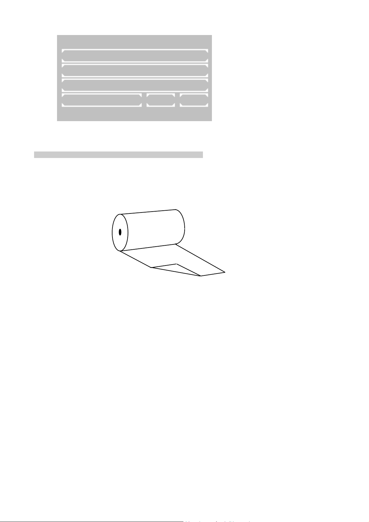
2.4 LOADING PRINTER PAPER
With initial operation or if the colored end of the paper roll appears, printer paper must be inserted:
• Open the printer cover and remove the rest of paper.
• Put printer paper axis into the new printer paper reel.
• Fold the beginning of paper over the corner to an angle of 90° (as shown below).
• Insert the bent paper underneath the ribbon cartridge.
• Press [LF] several times for line-feed until the paper has a length of about 5 cm.
• Insert printer paper reel into the axis guide.
• Push the printer paper through the slot in the printer cover and close the printer with the cover.
After around 15 minutes the device is heated
up and ready for measurement
.
First the tempering is switched off. If working
with tempered material is required later, switch
on the tempering already now either directly
by the utility program (chapter 7.2.9 Temperature ON / OFF) or indirectly by selection of a method with programmed tempering
(chapter 5.1 -
GENERAL NOTES).
ROBERT RIELE GmbH & Co KG Page 9 2 - INSTALLATION
5010e_513.doc / 22.01.10
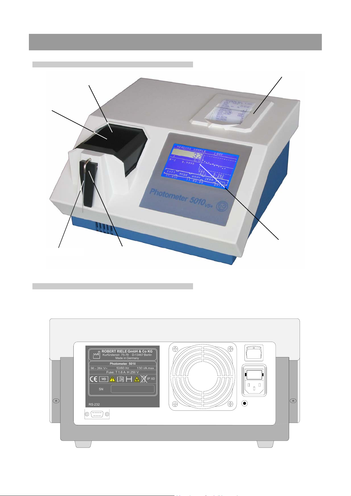
3 OPERATING ELEMENTS
3.1 FRONT
lid
working area
printer cover
aspiration tube
3.2 BACK
touchscreen
sipping lever [P]
ROBERT RIELE GmbH & Co KG Page 10 3 -
OPERATING ELEMENTS
5010e_513.doc / 22.01.10
3.3 TOUCHSCREEN
The touchscreen shows applications and
information. It is contact-sensitive and reacts
to the pressure exerted on it. In order to
execute a function, the desired range on the
screen must be touched
The surface of the touchscreen may
be never touched with ball-point pen, pencil
or another pointed article!
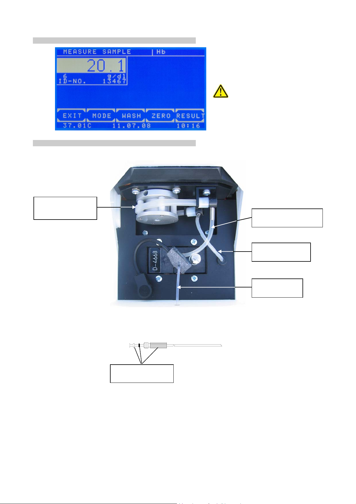
3.4 WORKING AREA
pump tube with joints
REF 5010-050
outlet tube cuvette
REF 5010-066
waste tubing
REF 1704834001
aspiration tubing
REF 5010-065
joint inlet tube cuvette
REF 1707175001
ROBERT RIELE GmbH & Co KG Page 11 3 - OPERATING ELEMENTS
5010e_513.doc / 22.01.10
3.5 CUVETTES AND CUVETTE ADAPTOR
3.5.1 Changing cuvette adaptor
If a flow system is installed, first the tubing system must be emptied: Go to the main menu and execute a
washing process by sipping lever [P] five times. Air is aspirated and the residual liquid is pumped off through the
waste tube.
Switch off the device.
If a flow system is installed, disconnect the bubble detector, remove the aspiration tube from the metal tube and
disconnect the outlet tube cuvette from the joints of the pump tube.
Loosen the milled screw and remove the adaptor.
Another adaptor can easily be inserted. Before check the cleanliness of the lense and the underside of the
adaptor. When inserting the adaptor electrical contacts in the device are closed. Turn milled screw only by hand!
3.5.2 Working with original flow-through system
Lead the aspiration tube with attached bubble detector without sharp bend from the working area through the
metal tube. Fasten outlet tube cuvette to the metal nipple of the cuvette as well as to the joint of the pump tube.
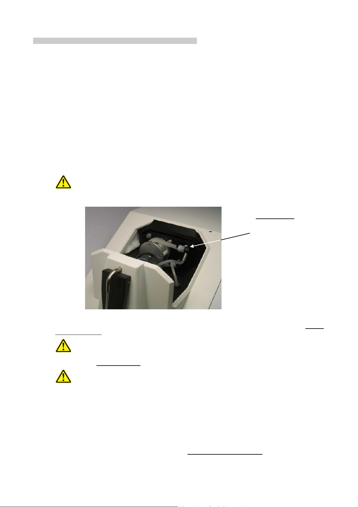
Before connecting the tubes remove pump tube at both ends from the metal clamps. The pump tube
must not be tensed during longer time out (fig. below).
Tension release:
The upper connection of
the pump tube can be
loosened easily from the
metal clamps.
Plug the bubble detector to the socket in the working area. It must sit as close as possible at the connection of
the flow-through cuvette. For working without bubble detector switch off this function (chapter 7.2.4.3 -
Bubble
detector ON / OFF).
While working with the flow-through system the tubes must not be sharply bended. No residues should
be inside. Check from time to time that the tubing and the connections are leakproof. After each replacement of
tubing execute a
Pump calibration (chapter 7.2.4.2).
Before as well as after all measuring it is absolutely necessary to wash the tube system repeatedly with
distilled water or another appropriate rinse solution by pressing [WASH] or sipping lever [P]. This is also necessary after a method change (chapter 8.1 - CLEANING INSTRUCTION). For the procedure within a measuring
series see the application regulation.
In order to aspirate solution into the measuring system put the aspiration tube deeply enough into the respective
vessel.
Before setting to zero press [ZERO]. Trigger setting to zero by sipping lever [P].
Trigger a normal measuring by sipping lever [P]. Repeat a measuring of a solution which is already aspirated by
[RESULT].
To work in optimized volume mode use the function
Volume optimized ON / OFF (chapter 7.2.4.3.2). This
function makes it possible, for example, to pump two consecutive times 500 µl from 1000 µl sample volume.
ROBERT RIELE GmbH & Co KG Page 12 3 - OPERATING ELEMENTS

5010e_513.doc / 22.01.10
3.5.3 Working with standard cuvettes
The path of rays is directed from the back to the front of the device. Insert single cuvette according to the
drawing OPTIC CONSTRUCTION in TECHNICAL DATA.
Trigger setting to zero by [ZERO].
Trigger a normal measuring by [RESULT].
3.5.4 Working with discrete flow-through cuvette
For use of a discrete flow-through cuvette insert the standard cuvette adaptor.
The path of rays is directed from the back to the front of the device. Insert flow-through cuvette according
to the drawing OPTIC CONSTRUCTION in TECHNICAL DATA.
Pay attention to the correct connection of aspiration tube and outlet tube cuvette.
Switch on the pump by the function
Pump ON / OFF (chapter 7.2.4.1).
Switch on or off bubble detector by the function
After the installation execute a
Pump calibration (chapter 7.2.4.2).
Bubble detector ON / OFF (chapter 7.2.4.3).
ROBERT RIELE GmbH & Co KG Page 13 3 - OPERATING ELEMENTS

5010e_513.doc / 22.01.10
4 PROGRAM SELECTION
After switch-on the touchscreen shows the main menu.
From this screen the basic methods (unalterably programmed in the system) or operator specific programmed
methods can be reached. Also the adjusting programs are started from this mask. With the method editor own
methods can be established and changed. The utility programs cover the configuration adjustments and check
routines. The lamp protection function can directly be reached by [LAMP], line feed of printer by [LF].
After completion of a method or execution of a utility program the program always returns to the main menu.
MAIN MENU
MEASURE WITH PROGR. METHODS
MEASURE WITH BASIC METHODS
METHODS NEW / CHANGE / COPY
UTILITIES LAMP LF
Main menu:
Down in the status line from left to right
following is shown:
• Current temperature of the cuvette adaptor
in °C.
In the case of switched off tempering the
display changes between --.--C und
xx.xxC.
In the case of switched on tempering and
instable temperature the display changes
between --.--C and e.g. 37.03C.
37.05C 09/08/09 11:39
In the case of stable temperature the
current temperature of e.g. 37.01C is
shown. Small fluctuations of the value are
normal.
• Date in the format day.month.year
• Time
4.1 Measurement with programmed methods
METHODS NO. 30
METHOD : Glucose
UNIT : mg/dl
1 2 3 4 5 6 7 8
ESC 9 0 . + - E
A programmed method for a photometric test
can be called
directly by input of the method
number.
The valid range for a method number lies
between 20 and 250.
Scroll all existing methods by [+] or [-]. If no
method is programmed, a plain text error
message (chapter 9.3 - PLAINTEXT ERROR
MESSAGES) is shown.
Call the selected method by [E].
Return to main menu by [ESC].
A programmed method can be established via menu METHOD NEW /CHANGE /
COPY (chapter 4.3 - Method editor).
The transmission of a method collection is
possible by PC with special software.
Further information:
Application sheets of reagent manufacturers
ROBERT RIELE GmbH & Co KG Page 14 4 -
PROGRAM SELECTION

5010e_513.doc / 22.01.10
4.2 Measurement with basic methods
A photometric test can be executed by a method already permanently programmed, but open in all setting
parameters. 14 different methods with different calculation procedures are available. Each of these methods can
serve as prototype for a method programmed by the operator.
BASIC METHODS PAGE 1/4
CONC. W. FACTOR PAGE
CONC. W. FACTOR RB
CONC. W. FACTOR SB
CONC. W. FACTOR RB SB EXIT
Available are:
• Absorbance measurement
• Concentration measurement / end point
measurement
• Fixed time kinetic / two point kinetic
• Kinetic
• Transmission
Scrolling through all methods is possible by
[PAGE]. The current page is shown at the
right upper screen corner. By [END] the
program returns to the main menu.
A method is selected by pressing the corresponding key.
The following abbreviations are used for the
distinction of the methods:
• CONC. = concentration
• KIN = kinetic
• F = factor
• STD = standard
• RB = reagent blank
• SB = sample blank
Further information:
Chapter: 5 - CALCULATION PROCEDURES
4.3 Method editor
METHOD NEW / CHANGE / COPY
METHOD COPY LIST
METHOD EDIT
METHOD NEW
METHOD DELETE EXIT
Each photometric test can be permanently
stored with its setting parameters by the
method editor.
With the functions of the method editor are
possible the new installation, the change and
removing a method.
By [LIST] an overview of the programmed
methods can be printed and transmitted via
the serial interface.
Further information:
37.05C 09/08/09 11:39
Chapter: 6 - METHOD EDITOR
ROBERT RIELE GmbH & Co KG Page 15 4 - PROGRAM SELECTION

5010e_513.doc / 22.01.10
4.4 Utility programs
UTILITIES PAGE 1/5
DARK ADJUSTMENT PAGE
MULTI-STANDARD
PRINTER
PUMP / BUBBLE DETECT EXIT
4.5 Lamp protection [LAMP]
MAIN MENU
LAMP PROTECTION
EXIT ON
37.05C 09/08/09 11:39
Utility programs are necessary for the adjustment and maintenance of Photometers 5010.
Further information:
Chapter: 7 - UTILITY PROGRAMS
37.05C 09/08/09 11:39
By [LAMP] in the main menu the halogen lamp
can be switched off temporarily to extend the
lifetime.
Activate the lamp protection by [ON].
Deactivate the lamp protection by [OFF]. After
60 s Photometer 5010 is again ready for
measuring.
Leave the function by [EXIT].
A zero adjustment should be repeated
by bringing in a zero solution and pressing
[ZERO].
4.6 Line feed [LF]
MAIN MENU
MEASURE WITH PROGR. METHODS
MEASURE WITH BASIC METHODS
METHODS NEW / CHANGE / COPY
UTILITIES LAMP LF
37.05C 09/08/09 11:39
Pressing [LF] in the main menu triggers a line
feed in the case of activated printer. Several
lines can be advanced by continuous pressure
on [LF].
ROBERT RIELE GmbH & Co KG Page 16 4 - PROGRAM SELECTION

5010e_513.doc / 22.01.10
5 CALCULATION PROCEDURES
5.1 GENERAL NOTES
The device offers operator guidance in the display by a combination of plaintext and short terms.
Messages and inputs regarding the method always have to be confirmed by [OK]. By [EXIT] all methods can be
broken off. For a restart see chapter 4 - PROGRAM SELECTION. Measuring is generally triggered by sipping
lever [P] or [RESULT], zero measuring by [ZERO] and sipping lever [P] (chapter 3.5.2 - Working with original
flow-through systemand 3.5.3 - Working with standard cuvettes -).
5.1.1 Fundamental to the handling ...
• Before measuring with standard cuvettes the lid of the cuvette compartment is to be closed.
•
5.1.2 Fundamental to the tempering ...
• Tempering switched on or off is parameter of a method.
• After switching on the tempering it lasts up to 10 minutes until a constant temperature of 25 °C, 30 °C
• The current temperature of the flow-through cuvette or of the cuvette adaptor is shown at the Iower
• For a quick mode of operation all temperature-sensitive samples, reagents and washing solutions
5.1.3 Fundamental to the inputs ...
• The input format of the factor and/or the standard with sign determines the output format of the result
• Each factor or standard can be minus signed, so that the result is calculated with correct sign.
• For a homogeneous solution the input of a delay before a measuring is possible at all methods.
• All delay times can be cancelled by pressing the aspiration tube [P] for a long time.
Deviations from normal operation, caused by the device or by the operator, are notified by
“ERROR”. They always have to be confirmed by [E] (chapter 9 - ERROR MESSAGE /
CORRECTION).
Example 1: The reading exceeds the programmed upper limit
Example 2: Too little liquid when sucking in a measuring solution
or 37 °C is reached.
edge of the touchscreen. For meaning of the display see chapter 4 - PROGRAM SELECTION /MAIN
MENU. A temperature instable or out of tolerance during measuring is marked by an asterisk (*) at the
utmost right position in the corresponding print line.
To avoid deviations due to temperature influence a delay between triggering and actual measuring can
be programmed in each method.
should be externally tempered by Incubator T12/T16 (REF 500-002 / 500-001) or a water bath.
concerning the number of decimal places.
Example: With factor “36.8” the calculated concentration will be shown with one decimal place.
Example: The test GOT is programmed with the factor “-1746“ because the measuring principle implies
a decreasing absorbance.
ROBERT RIELE GmbH & Co KG Page 17 5 -
CALCULATION PROCEDURES

5010e_513.doc / 22.01.10
5.1.4 Fundamental to the methods with standard ... 5.1.4 Fundamental to the methods with standard ...
• Each measuring of a standard (calibrator) can be executed as single, double or triple determination.
• Each measuring of a standard (calibrator) can be executed as single, double or triple determination.
Following is shown:
Following is shown:
MEASURE ST Glucose
ST[A]
0.616
0.612
0.617
OK CURS. DEL. RESULT
37.05C 09/08/09 11:39
• The determined resulting factor of a standard measurement is stored together with the corresponding
method number. After renewed selection of this method the last resulting factor is offered as "OLD
STD".
• The principle of the multiple measurement can also be expanded to all measurements. The
corresponding entry can be set invoking a basic method. The parameter is definable in preprogrammed methods (chapter 6 - METHOD EDITOR).
5.1.5 Fundamental to the methods with multi-standards ...
In the white reading window the
averaged absorbance of the standard
is shown.
Below the white reading window the
absorbance 1, 2 and 3 of a standard
are shown.
By [OK] the average of all values is
taken over. Values with 0 are ignored
and excluded from the calculation.
The resulting factor is calculated from
the average of the standard.
By [CURS.] a value is selected. A
flashing white square marks the
current value.
By [DEL.] a value is deleted and
excluded from the calculation.
By [RESULT] a measuring is
triggered.
• Linear calibration is used in the case of two calibrators. The absorbance forms a linear diagram with
the concentrations (chapter 7.2.2 - Multi-standard functions).
• Nonlinear calibration is used for samples with a nonlinear but reproducible connection between the
absorbance and the concentrations. At least three (maximum 20) calibrators are required for nonlinear
calibration (chapter 7.2.2 - Multi-standard functions).
5.1.6 Fundamental to bichromatic measurements …
• The calculation procedures based on endpoint measurement (CP 1 to CP 8, CP 13 and CP 14) can be
executed bichromatic. The zero measurement will be done with a wavelength defined as bichromatic.
The bichromatic wavelength might be not included in the standard set of filters. The bichromatic
wavelength can be set after calling a method (chapter 6 METHOD EDITOR Fig. 6.5).
ROBERT RIELE GmbH & Co KG Page 18 5 - CALCULATION PROCEDURES CALCULATION PROCEDURES

5010e_513.doc / 22.01.10
5.1.7 Fundamental to the Kinetic…
In a kinetic method the sample absorbance is measured several times in pre-established time intervals.
The user can define a delay time and a quantity and duration of time intervals after the delay time (Deltas or ∆t).
At the beginning and at the end of the delay time the absorbance values ABS.1 and ABS.2 are measured
respectively. The difference |ABS.1 – ABS.2| allows the differentiation between normal and abnormal activities.
This is followed by a sequence of measurements in regular time intervals (Deltas or ∆t). An example of a
resulting curve is shown in Fig. 5.1.7.1:
Fig. 5.1.7.1: Resulting curve of kinetic test, decreasing absorbance
In each time interval (Delta or ∆t) the difference between the relating absorbance values as well as the gradient
of the curve are calculated.
To obtain the alteration per minute ∆A
the gradients must be averaged. This is done by a simple linear
S,Minute
regression calculation also giving an indicator for the linearity of the test. This indicator is called the coefficient of
correlation R. For practical reasons, the square of the coefficient of correlation R^2 or coefficient of
determination is taken in a Kinetic calculation. The value of R^2 can vary between 0 and 1. An R^2 value of 1
indicates perfect linearity and a value of 0 indicates absolute non-linearity. Already values < 0.9 indicate a bad
linearity and therefore an incorrect test.
In practice, linear tests show values of R^2 near to 1. In the example for Calculation procedure 11 (KIN/F/Rb)
values of R^2 ≥ 0.998 are permitted. Results with smaller R^2 values could be caused by temperature
instability, pollution, expired reagents, unfavorable delay time, etc.
For a better monitoring the number of deltas (deltas or ∆t) should be bigger than specified for the manual
procedure. The classic three-minutes-test with three deltas of 60 s can be replaced by 15 deltas of 12s.
When programming a new method, which is based on CP 11 or CP 12, it is possible to set lower and upper
limits for the measurement result within the method editor (see chapter 6 - METHOD EDITOR,
Fig. 6.5). This
can be achieved setting the parameters MIN. VALUE and MAX. VALUE. If the measured value exceeds the
MAX. VALUE a message RANGE MAX. is shown and if the measured value falls below MIN. VALUE message
RANGE MIN. is shown. Also a lower limit for R^2 can be entered by setting MIN. R^2, if the obtained R^2 value
falls below the entered value a message RANGE R^2 is shown.
In order to get positive results at tests with decreasing absorbance (see Fig. 5.1.7.1), a negative factor has to be
entered. Only if MAX. VALUE is set and the sign of the measured value is not equal to the sign of the entered
MAX. VALUE a message RANGE +/- is shown.
The parameters MIN. VALUE, MAX. VALUE and MIN. R^2 are deactivated entering a zero value.
ROBERT RIELE GmbH & Co KG Page 19 5 - CALCULATION PROCEDURES

5010e_513.doc / 22.01.10
5.1.8 Fundamental to the methods with reagent blank… 5.1.8 Fundamental to the methods with reagent blank…
REAGENT BLANK
EDIT MEAS.
After selecting a method with reagent
blank (RB), the reagent blank can be
measured, entered or put on zero.
Press [EDIT] to enter the RB
manually or [MEAS.] to measure it.
OLD RB 0.110
NO YES
5.1.9 Fundamental to ID-NO. and sample numerator…
• All test results are labeled with a numerator.
• Additionally, all results can be labeled with a 5-digit ID-NO. When the ID-NO. is not zero it will be
displayed and printed together with the sample result.
• When a method is selected you can edit both numerator and ID-NO. of a sample with [MODE] [NUM.]
NEW SAMPLE NO. 1-99
1 2 3 4 5 6 7 8
ESC 9 0 . + - N/I E
When using a programmed method
based on a calculation procedure
with RB, the used RB will be stored
together with the corresponding
method number.
After renewed selection of this
method the last stored reagent blank
is offered as “OLD RB”.
Press [YES] to use the last stored RB
or [NO] to enter or measure it.
Press [N / I] to switch between editing
numerator and ID-NO.
5.1.10 Fundamental to storing test results…
• All test results are stored automatically. Up to 1000 results can be stored in memory.
• See Table 7.2.5.1 for the format of the stored data.
• Stored results can be output through serial interface (chapter 7.2.19).
• When memory is full oldest test results will be overwritten or you can send all results through the serial
interface and then delete them.
ROBERT RIELE GmbH & Co KG Page 20 5 - CALCULATION PROCEDURES CALCULATION PROCEDURES

5010e_513.doc / 22.01.10
5.2 ABBREVIATIONS
A, ABS ..................Absorbance
........................ Absorbance of reagent blank
A
RB
...................... At Fixed Time: absorbance of reagent blank after incubation time T0
A
RB,0
...................... At Fixed Time: absorbance of reagent blank after reaction time T
A
RB,1
A
....................... Absorbance of blank of reagent blank
RBB
.......................... Absorbance of sample
A
S
A
........................ At Fixed Time: absorbance of sample after incubation time T0
S,0
........................ At Fixed Time: absorbance of sample after reaction time T1
A
S,1
........................ Absorbance of sample blank
A
SB
......................... Absorbance of standard
A
ST
....................... At Fixed Time: absorbance of standard after incubation time T0
A
ST,0
....................... At Fixed Time: absorbance of standard after reaction time T
A
ST,1
A
....................... Absorbance of standard blank
STB
C ...........................Concentration
........................ Concentration of standard
C
ST
CV......................... Quality control: Coefficient of variation
dA/min................... At Kinetic: ∆A / min
∆A
∆A
................ At Kinetic: change of reagent blank per minute (measured in ∆A / min)
RB,Minit
.................. At Kinetic: change of sample per minute (measured in ∆A / min)
S,Minit
F............................ Factor
FTK .......................Fixed Time Kinetic
KIN........................ Kinetic
n............................ Quality control: number of values
nm......................... Nanometer (dimension of wavelength)
m........................... Quality control: mean of values
R ...........................Result, Sample
Rb .........................Reagent blank
Rbb .......................Blank of reagent blank
R^2........................ At Kinetic: square of correlation coefficient
or coefficient of determination shows the linearity of a test
S, ST..................... Standard
STb .......................Standard blank
Sb.......................... Sample blank
s ............................Quality control: standard deviation
TRANSM., T.......... Transmission in %
.......................... At Fixed Time: incubation time in seconds
T
0
.......................... At Fixed Time: reaction time in seconds
T
1
.......................... At Kinetic: time per delta in seconds
T
1
1
1
ROBERT RIELE GmbH & Co KG Page 21 5 - CALCULATION PROCEDURES
5010e_513.doc / 22.01.10
5.3 SURVEY OF THE METHODS
The calculation procedures, on which all methods are traceable from the list of methods, are mentioned in the
following table. Criterion is the characteristic of the calculation procedure (see below). For detailed description of
the respectively accompanying procedure of method see chapter 5.4 - DESCRIPTION OF METHOD
PROCEDURES.
CP-No. Characteristic Method Calculation formula
CP 1 C/F Endpoint with Factor
CP 2 C/F/Rb Endpoint with Factor
CP 3 C/F/Sb Endpoint with Factor
CP 4 C/F/SbRb Endpoint with Factor
CP 5 C/S Endpoint with Standard
CP 6 C/S/Rb Endpoint with Standard
CP 7 C/S/Sb Endpoint with Standard
CP 8 C/S/SbRb Endpoint with Standard
CP 9 FTK/F/Rb Fixed Time Kinetic with Factor
CP 10 FTK/S/Rb Fixed Time Kinetic with Standard
CP 11 KIN/F/Rb Kinetic with Factor
CP 12 KIN/S/Rb Kinetic with Standard
CP 13 TRANSM. Transmission in %
CP 14 C/F DELTA Endpoint with Factor
CP 15 C/F 3 WL Measurement with 3 Wavelengths C = 168 * A
Explanations:
CP-No. ........................Number of the calculation procedure (chapter 6 - METHOD EDITOR)
Characteristic ..............Name of the calculation procedure (chapter 12.1 - BASIC METHOD)
Calculation formula .....Calculation basis of basic method
C = F ∗ A
C = F ∗ (A
C = F ∗ |A
S
S
S
C = F ∗ (|A
C = F ∗ A
C = F ∗ (A
C = F ∗ |A
S
S
S
C = F ∗ (|A
C = F ∗ ( |A
C = F ∗ ( |A
C = F ∗ ( ∆A
C = F ∗ ( ∆A
C = F ∗ ( ∆A
- ARB)
- ASB|
- ASB| - |ARB - A
S
- ARB)
- ASB|
- ASB| - |ARB - A
S
- A
- A
S,Minit
S,Minit
S2-Sb2
| - |A
S,1
| - |A
S,1
- ∆A
RB,Minit
- ∆A
RB,Minit
- ∆A
S1-Sb1
– 84 * A
S,0
S,0
415nm
RB,0
RB,0
380nm
|)
RBB
|)
RBB
- A
RB,1
- A
RB,1
)
)
)
– 84 * A
| )
| )
450nm
ROBERT RIELE GmbH & Co KG Page 22 5 - CALCULATION PROCEDURES

5010e_513.doc / 22.01.10
5.4 DESCRIPTION OF METHOD PROCEDURES
In the descriptions of the calculation procedures a typical print-out by the internal printer is shown on the left
side. All examples were built with active pump. In case of measurements without pump the volumes for sipping
the media are not printed.
All print-outs begin with the device information, laboratory data and method parameters followed by all measuring data necessary for a manual examination of the readings.
The measuring window
The arrangement of the measuring window is alike in all calculation procedures. Depending on the method,
various numbers of readings or diagrams are shown.
status of measuring system or
name of active method
next action
reading window
numerator
ID number
dimension
action keys
info line
MEASURE SAMPLE Glucose
3 mmol/l
ID-NO. 13467
EXIT MODE WASH ZERO RESULT
37.05C 09/08/09 11:39
16.5
Additional method
specific information
Functions of the action keys in the measuring window:
[EXIT] Leads to the query whether the measuring program is to be terminated.
[MODE] Occupies the action keys with following mode functions:
[NUM.] [MODE] [LF] [QC] [RETURN]
[PRN] [DETAIL] [LAMP] [M-STD] [RETURN]
[WASH] With activated pump the wash volume defined to the method is pumped.
[ZERO] Starts the zero measuring.
With activated pump the sipping lever [P] must also be pressed.
[RESULT] Starts the measuring.
With activated pump a solution already sipped is measured once again.
To aspirate and measure a new sample press sipping lever [P] .
Mode functions:
[NUM.] Edit sample numerator or ID-NO. (chapter 5.1.9)
[LF] Line Feed.
[QC] Quality Control functions.
[PRN] Switch printer on / off.
[DETAIL] Print detailed results on kinetic measurement.
[LAMP] Lamp Protection (chapter 4.5).
[M-STD] Multi standard functions.
[RETURN] Return to normal functions.
ROBERT RIELE GmbH & Co KG Page 23 5 - CALCULATION PROCEDURES

5010e_513.doc / 22.01.10
5.4.1 Calculation procedure 1 (C/F)
Method at which a measured sample value A
Calculation procedure .......................................................CP 1
Characteristic ....................................................................C / F
Method ....................................................End Point with Factor
Calculation formula ..................................................C = F ∗ A
Factor............................................................... given / entering
is multiplied with a predefined factor F.
S
S
PHOTOMETER 5010 #7000
V5.13a 02/09/09 D
LAB.: RIELE GMBH+CO KG
DATE: 09/08/09
TIME: 08:44:12
METHOD 20: HEMOGLOBIN
PROGRAM: 1
FACTOR: 29.4
WAVELENGTH: 405nm
TEMPERATURE: 37C
MEAS. VOLUME: 900ul
WASH VOLUME: 1000ul
DELAY: 5s
MAX.UNITS: 25
UNIT: g/l
- - - - - - - - - - - -
MEASURE BLANK
NO. ABS. RESULT
- - - - - - - - - - - -
1 0.675 19.8
- - - - - - - - - - - -
2 0.843 24.8
- - - - - - - - - - - -
Start method selection in the main menu.
See chapter:
4.1 - Measurement with programmed methods
4.2 - Measurement with basic methods
In the case of activated printer the print-out of the method data
follows.
The measuring window is shown.
Method procedure:
ÆInsert / measure zero solution
ÆInsert / measure sample
ÆInsert / measure sample
ROBERT RIELE GmbH & Co KG Page 24 5 - CALCULATION PROCEDURES

5010e_513.doc / 22.01.10
5.4.2 Calculation procedure 2 (C/F/Rb)
Method at which the difference of sample value A
The reagent blank A
is entered or measured once.
RB
Calculation procedure .......................................................CP 2
Characteristic ............................................................ C / F / Rb
Method ....................................................End Point with Factor
Calculation formula .......................................C = F ∗ (A
Factor............................................................... given / entering
Reagent blank........................................entering or measuring
and reagent blank ARB is multiplied with a given factor F.
S
- ARB)
S
PHOTOMETER 5010 #7000
V5.13a 02/09/09 D
LAB.: RIELE GMBH+CO KG
DATE: 09/08/09
TIME: 08:52:24
METHOD 21: HDL-C
PROGRAM: 2
FACTOR: 325
WAVELENGTH: 546nm
TEMPERATURE: 37C
MEAS. VOLUME: 900ul
WASH VOLUME: 1000ul
DELAY: 5s
UNIT: mg/dl
- - - - - - - - - - - -
MEASURE BLANK
Rb[A]: 0.058
NO. ABS. RESULT
- - - - - - - - - - - -
1 1.064 327
- - - - - - - - - - - -
2 1.188 367
- - - - - - - - - - - -
3 1.340 417
- - - - - - - - - - - -
Start method selection in the main menu.
See chapter:
4.1 - Measurement with programmed methods
4.2 - Measurement with basic methods
In the case of activated printer the print-out of the method data
follows.
The measuring window is shown.
Method procedure:
ÆInsert / measure zero solution
ÆInsert / measure reagent blank
ÆInsert / measure sample
ÆInsert / measure sample
ÆInsert / measure sample
ROBERT RIELE GmbH & Co KG Page 25 5 - CALCULATION PROCEDURES

5010e_513.doc / 22.01.10
5.4.3 Calculation procedure 3 (C/F/Sb)
Method at which the difference of sample value A
a given factor F. The sample blank A
Calculation procedure .......................................................CP 3
Characteristic ............................................................ C / F / Sb
Method ....................................................End Point with Factor
Calculation formula ....................................... C = F ∗ |A
Factor............................................................... given / entering
and sample blank ASB regarding the amount is multiplied with
is measured before every test.
SB
S
- ASB|
S
PHOTOMETER 5010 #7000
V5.13a 02/09/09 D
LAB.: RIELE GMBH+CO KG
DATE: 09/08/09
TIME: 09:45:32
METHOD 23: BILIRUBIN
PROGRAM: 3
FACTOR: 12.80
WAVELENGTH: 546nm
TEMPERATURE: 37C
MEAS. VOLUME: 900ul
WASH VOLUME: 1000ul
DELAY: 5s
MAX.UNITS: 8.0
UNIT: mg/dl
- - - - - - - - - - - -
MEASURE BLANK
NO. ABS. RESULT
1 1.000 4.21
Sb[A]: 0.671
- - - - - - - - - - - -
2 1.215 4.25
Sb[A]: 0.884
- - - - - - - - - - - -
3 1.033 4.23
Sb[A]: 0.702
- - - - - - - - - - - -
Start method selection in the main menu.
See chapter:
4.1 - Measurement with programmed methods
4.2 - Measurement with basic methods
In the case of activated printer the print-out of the method data
follows.
The measuring window is shown.
Method procedure:
ÆInsert / measure zero solution
ÆInsert / measure sample blank
ÆInsert / measure sample
ÆInsert / measure sample blank
ÆInsert / measure sample
ÆInsert / measure sample blank
ÆInsert / measure sample
ROBERT RIELE GmbH & Co KG Page 26 5 - CALCULATION PROCEDURES

5010e_513.doc / 22.01.10
5.4.4 Calculation procedure 4 (C/F/SbRb)
Method at which the difference of reagent blank A
subtracted of the difference of sample value A
is multiplied with a given factor F.
The sample blank A
is measured before every test. The reagent blank ARB is entered or measured once.
SB
Calculation procedure .......................................................CP 4
Characteristic ........................................................C / F / SbRb
Method ....................................................End Point with Factor
Calculation formula ..............C = F ∗ ( |A
Factor............................................................... given / entering
Reagent blank........................................entering or measuring
and blank of reagent blank A
RB
and sample blank ASB regarding the amount, and this difference
S
- ASB| - |ARB - A
S
RBB
| )
regarding the amount is
RBB
PHOTOMETER 5010 #7000
V5.13a 02/09/09 D
LAB.: RIELE GMBH+CO KG
DATE: 09/08/09
TIME: 10:11:15
METHOD 24: Fe
PROGRAM: 4
FACTOR: 1330
WAVELENGTH: 578nm
TEMPERATURE: 37C
MEAS. VOLUME: 900ul
WASH VOLUME: 1000ul
DELAY: 5s
MIN.UNITS: 37
MAX.UNITS: 158
UNIT: ug/dl
- - - - - - - - - - - -
MEASURE BLANK
Rb[A]: 0.085
Rbb[A]: 0.198
DELTA Rb: 0.113
NO. ABS. RESULT
1 0.715 154
Sb[A]: 0.486
- - - - - - - - - - - -
2 0.646 49
Sb[A]: 0.497
- - - - - - - - - - - -
Start method selection in the main menu.
See chapter:
4.1 - Measurement with programmed methods
4.2 - Measurement with basic methods
In the case of activated printer the print-out of the method data
follows.
The measuring window is shown.
Method procedure:
ÆInsert / measure zero solution
ÆInsert / measure blank of reagent blank
ÆInsert / measure reagent blank
(Resulting blank)
ÆInsert / measure sample blank
ÆInsert / measure sample
ÆInsert / measure sample blank
ÆInsert / measure sample
ROBERT RIELE GmbH & Co KG Page 27 5 - CALCULATION PROCEDURES

5010e_513.doc / 22.01.10
5.4.5 Calculation procedure 5 (C/S)
Method at which a measured absorbance value A
ing of a standard solution with known concentration C
Calculation procedure .......................................................CP 5
Characteristic ....................................................................C / S
Method ............................................... End Point with Standard
Calculation formula ..................................................C = F ∗ A
Resulting factor .................................................... F = C
is multiplied with a factor F which is determined by measur-
S
.
ST
S
/ A
ST
ST
PHOTOMETER 5010 #7000
V5.13a 02/09/09 D
LAB.: RIELE GMBH+CO KG
DATE: 09/08/09
TIME: 08:33:42
METHOD 25: GLUCOSE
PROGRAM: 5
STANDARD: 5.55
WAVELENGTH: 546nm
TEMPERATURE: 37C
MEAS. VOLUME: 900ul
WASH VOLUME: 1000ul
DELAY: 3s
MAX.UNITS: 22.2
UNIT: mmol/l
- - - - - - - - - - - -
MEASURE BLANK
ST[A] 1: 1.110
ST[A] 2: 1.093
ST[A] 3: 1.059
ST[A]: 1.088
FACTOR: 5.10
NO. ABS. RESULT
- - - - - - - - - - - -
1 1.026 5.23
- - - - - - - - - - - -
2 1.357 6.92
- - - - - - - - - - - -
3 1.582 8.07
Start method selection in the main menu.
See chapter:
4.1 - Measurement with programmed methods
4.2 - Measurement with basic methods
In the case of activated printer the print-out of the method data
follows.
The measuring window is shown.
Method procedure:
ÆInsert / measure zero solution
ÆInsert / measure standard 1
ÆInsert / measure standard 2 (optional)
ÆInsert / measure standard 3 (optional)
(Averaged standard)
(Resulting factor)
ÆInsert / measure sample
ÆInsert / measure sample
ÆInsert / measure sample
ROBERT RIELE GmbH & Co KG Page 28 5 - CALCULATION PROCEDURES

5010e_513.doc / 22.01.10
5.4.6 Calculation procedure 6 (C/S/Rb)
Method at which the difference of sample value A
determined by measuring of a standard solution with known concentration C
reagent blank A
The reagent blank A
.
RB
is entered or measured once.
RB
Calculation procedure .......................................................CP 6
Characteristic ............................................................C / S / Rb
Method ............................................... End Point with Standard
Calculation formula .......................................C = F ∗ (A
Resulting factor ...........................................F = C
Reagent blank........................................entering or measuring
and reagent blank ARB is multiplied with a factor F which is
S
- ARB)
S
/ (AST-ARB)
ST
and under consideration of
ST
PHOTOMETER 5010 #7000
V5.13a 02/09/09 D
LAB.: RIELE GMBH+CO KG
DATE: 09/08/09
TIME: 08:45:09
METHOD 26: SODIUM
PROGRAM: 6
STANDARD: 150.0
WAVELENGTH: 405nm
TEMPERATURE: 37C
MEAS. VOLUME: 900ul
WASH VOLUME: 1000ul
DELAY: 3s
MAX.UNITS: 300
UNIT: mmol/l
- - - - - - - - - - - -
MEASURE BLANK
Rb[A]: 0.108
ST[A] 1: 1.112
ST[A] 2: 1.132
ST[A] 3: 1.118
ST[A]: 1.121
FACTOR: 148.2
NO. ABS. RESULT
- - - - - - - - - - - -
1 1.449 198.7
- - - - - - - - - - - -
2 1.118 149.6
- - - - - - - - - - - -
5 2.006 281.2
Start method selection in the main menu.
See chapter:
4.1 - Measurement with programmed methods
4.2 - Measurement with basic methods
In the case of activated printer the print-out of the method data
follows.
The measuring window is shown.
Method procedure:
ÆInsert / measure zero solution
ÆInsert / measure reagent blank
ÆInsert / measure standard 1
ÆInsert / measure standard 2 (optional)
ÆInsert / measure standard 3 (optional)
(Averaged standard)
(Resulting factor)
ÆInsert / measure sample
ÆInsert / measure sample
ÆInsert / measure sample
ROBERT RIELE GmbH & Co KG Page 29 5 - CALCULATION PROCEDURES

5010e_513.doc / 22.01.10
5.4.7 Calculation procedure 7 (C/S/Sb)
Method at which the difference of sample value A
a factor F which is determined by measuring of a standard solution with known concentration C
consideration of standard blank A
STB.
The sample blank ASB is measured before every test.
Calculation procedure .......................................................CP 7
Characteristic ............................................................ C / S / Sb
Method ............................................... End Point with Standard
Calculation formula ....................................... C = F ∗ |A
Resulting factor ........................................ F = C
and sample blank ASB regarding the amount is multiplied with
S
/ |AST - A
ST
- ASB|
S
STB
|
and under
ST
PHOTOMETER 5010 #7000
V5.13a 02/09/09 D
LAB.: RIELE GMBH+CO KG
DATE: 09/08/09
TIME: 08:55:25
METHOD 27: UREA COL
PROGRAM: 7
STANDARD: 50.0
WAVELENGTH: 546nm
TEMPERATURE: 37C
MEAS. VOLUME: 900ul
WASH VOLUME: 1000ul
DELAY: 3s
MAX.UNITS: 220
UNIT : mg/dl
- - - - - - - - - - - -
MEASURE BLANK
ST[A] 1: 0.614
ST[A] 2: 0.629
ST[A] 3: 0.620
ST[A]: 0.621
STb[A]: 0.106
DELTA ST: 0.515
FACTOR: 97.1
NO. ABS. RESULT
1 2.292 197.6
Sb[A]: 0.257
- - - - - - - - - - - -
2 2.340 198.0
Sb[A]: 0.300
- - - - - - - - - - - -
3 2.223 197.2
Sb[A]: 0.193
- - - - - - - - - - - -
Start method selection in the main menu.
See chapter:
4.1 - Measurement with programmed methods
4.2 - Measurement with basic methods
In the case of activated printer the print-out of the method data
follows.
The measuring window is shown.
Method procedure:
ÆInsert / measure zero solution
ÆInsert / measure standard blank
ÆInsert / measure standard 1
ÆInsert / measure standard 2 (optional)
ÆInsert / measure standard 3 (optional)
(Averaged standard)
(standard blank)
(Averaged standard minus standard blank)
(Resulting factor)
ÆInsert / measure sample blank
ÆInsert / measure sample
ÆInsert / measure sample blank
ÆInsert / measure sample
ÆInsert / measure sample blank
ÆInsert / measure sample
ROBERT RIELE GmbH & Co KG Page 30 5 - CALCULATION PROCEDURES

5010e_513.doc / 22.01.10
5.4.8 Calculation procedure 8 (C/S/SbRb)
Method at which the difference of reagent blank A
subtracted of the difference of sample value A
is multiplied with a factor F which is determined by measuring of a standard solution with known concentration
and under consideration of standard blank A
C
ST
reagent blank A
RBB
The sample blank ASB is measured before every test. The reagent blank ARB is entered or measured once.
Calculation procedure .......................................................CP 8
Characteristic ........................................................C / S / SbRb
Method ............................................... End Point with Standard
Calculation formula ..............C = F ∗ ( |A
Resulting factor ...................F = C
/ ( |AST-A
ST
Reagent blank........................................entering or measuring
and blank of reagent blank A
RB
and sample blank ASB regarding the amount and this difference
S
and the difference of reagent blank ARB and blank of
STB
- ASB| - |ARB - A
S
| - |ARB-A
STB
RBB
RBB
| )
| )
regarding the amount is
RBB
PHOTOMETER 5010 #7000
V5.13a 02/09/09 D
LAB.: RIELE GMBH+CO KG
DATE: 09/08/09
ZEIT: 09:33:26
METHOD 28: Ca
PROGRAM: 8
STANDARD: 8.02
WAVELENGTH: 546nm
TEMPERATURE: 37C
MEAS. VOLUME: 900ul
WASH VOLUME: 1000ul
DELAY: 3s
MAX.UNITS: 12
UNIT: mg/dl
- - - - - - - - - - - -
MEASURE BLANK
Rb[A]: 0.150
Rbb[A]: 0.046
DELTA Rb: 0.104
ST[A] 1: 1.485
ST[A] 2: 1.521
ST[A] 3: 1.495
ST[A]: 1.501
STb[A]: 0.479
DELTA ST: 1.022
FACTOR: 8.74
NO. ABS. RESULT
1 1.495 7.89
Sb[A]: 0.489
- - - - - - - - - - - -
2 1.542 7.89
Sb[A]: 0.535
- - - - - - - - - - - -
3 1.394 8.39
Sb[A]: 0.329
- - - - - - - - - - - -
Start method selection in the main menu.
See chapter:
4.1 - Measurement with programmed methods
4.2 - Measurement with basic methods
In the case of activated printer the print-out of the method data
follows.
The measuring window is shown.
Method procedure:
ÆInsert / measure zero solution
ÆInsert / measure blank of reagent blank
ÆInsert / measure reagent blank
(Resulting blank)
ÆInsert / measure standard blank
ÆInsert / measure standard 1
ÆInsert / measure standard 2 (optional)
ÆInsert / measure standard 3 (optional)
(Averaged standard)
(standard blank)
(Averaged standard minus standard blank)
(Resulting factor)
ÆInsert / measure sample blank
ÆInsert / measure sample
ÆInsert / measure sample blank
ÆInsert / measure sample
ÆInsert / measure sample blank
ÆInsert / measure sample
ROBERT RIELE GmbH & Co KG Page 31 5 - CALCULATION PROCEDURES

5010e_513.doc / 22.01.10
5.4.9 Calculation procedure 9 (FTK/F/Rb)
Method at which a reagent blank is measured after an incubation time (⇒ A
) and also a sample after an incubation time (⇒ A
A
RB,1
) and after a reaction time (⇒ A
S,0
) and after a reaction time (⇒
RB,0
).
S,1
The difference from the change of the test and the change of the reagent blank is multiplied by a predefined
factor F. The reagent blank A
is entered or measured once.
RB
During the procedure the dialog asks for the use of a reagent blank. The default value is OFF. To continue without reagent blank press [ENTER].
After each measurement the next sample can be measured with [NEXT].
With [RESULT] it is possible to measure the same sample again.
Calculation procedure .......................................................CP 9
Characteristic ........................................................FTK / F / Rb
Method ................................................. Fixed Time with Factor
Calculation formula .........C = F ∗ ( |A
S,0
S,1
| - |A
RB,0
- A
RB,1
| )
- A
Factor............................................................... given / entering
Reagent blank........................................entering or measuring
PHOTOMETER 5010 #7000
V5.13a 02/09/09 D
LAB.: RIELE GMBH+CO KG
DATE: 09/08/09
TIME: 09:47:33
METHOD 29: CK-MB
PROGRAM: 9
FACTOR: 2751.3
WAVELENGTH: 340nm
TEMPERATURE: 37C
MEAS. VOLUME: 900ul
WASH VOLUME: 1000ul
INCUBATION: 120s
REACTION: 180s
MAX.UNITS: 1500
UNIT: U/l
- - - - - - - - - - - -
MEASURE BLANK
Rb[A]: 0.000
NO. ABS. RESULT
- - - - - - - - - - - -
1 1.005 910.7
DELTA [A]: 0.331
- - - - - - - - - - - -
2 1.029 1128.1
DELTA [A]: 0.410
- - - - - - - - - - - -
3 0.829 1381.2
DELTA [A]: 0.502
Start method selection in the main menu.
See chapter:
4.1 - Measurement with programmed methods
4.2 - Measurement with basic methods
In the case of activated printer the print-out of the method data
follows.
The measuring window is shown.
Method procedure:
ÆInsert / measure zero solution
Without reagent blank (insert / measure optionally)
ÆInsert / measure sample
ÆInsert / measure sample
ÆInsert / measure sample
ROBERT RIELE GmbH & Co KG Page 32 5 - CALCULATION PROCEDURES

5010e_513.doc / 22.01.10
5.4.10 Calculation procedure 10 (FTK/S/Rb)
Method at which a reagent blank is measured after an incubation time (⇒ A
) and also a sample after an incubation time (⇒ A
A
RB,1
) and after a reaction time (⇒ A
S,0
) and after a reaction time (⇒
RB,0
).
S,1
The difference from the change of the sample and the change of the reagent blank becomes multiplied with a
factor F which is determined by means of the change of standard solution |A
reagent blank |A
RB,0-ARB,1
| during the reaction time and given concentration of standard. The reagent blank ARB
ST,0-AST,1
| and the change of
is entered or measured once.
During the procedure the dialog asks for the use of a reagent blank. The default value is OFF. To continue without reagent blank press [ENTER].
After each measurement the next sample can be measured with [NEXT].
With [RESULT] it is possible to measure the same sample again.
Calculation procedure .....................................................CP 10
Characteristic ........................................................FTK / S / Rb
Method ............................................. Fixed Time with Standard
Calculation formula .........C = F ∗ ( |A
Resulting factor ..............F = C
ST
/ ( |A
S,0
S,1
ST,0-AST,1
| - |A
| - |A
- A
RB,0
RB,0-ARB,1
RB,1
| )
| )
- A
Reagent blank........................................entering or measuring
PHOTOMETER 5010 #7000
V5.13a 02/09/09 D
LAB.: RIELE GMBH+CO KG
DATE: 09/08/09
TIME: 10:03:16
METHOD 30: CREATININ
PROGRAM: 10
STANDARD: 2.00
WAVELENGTH: 492nm
TEMPERATURE: 37C
MEAS. VOLUME: 900ul
WASH VOLUME: 1000ul
INCUBATION: 45s
REACTION: 60s
MAX.UNITS: 25
UNIT: mg/dl
- - - - - - - - - - - -
MEASURE BLANK
Rb[A]: 0.000
ST/KIN 1: 0.194
ST/KIN 2: 0.203
ST/KIN 3: 0.214
ST/KIN: 0.204
FACTOR: 9.80
NO. ABS. RESULT
- - - - - - - - - - - -
1 0.326 9.84
DELTA [A]: 1.005
- - - - - - - - - - - -
2 0.336 10.81
DELTA [A]: 1.103
- - - - - - - - - - - -
3 0.329 12.84
DELTA [A]: 1.310
Start method selection in the main menu.
See chapter:
4.1 - Measurement with programmed methods
4.2 - Measurement with basic methods
In the case of activated printer the print-out of the method data
follows.
The measuring window is shown.
Method procedure:
ÆInsert / measure zero solution
Without reagent blank (insert / measure optionally)
ÆInsert / measure standard 1
ÆInsert / measure standard 2 (optional)
ÆInsert / measure standard 3 (optional)
(Averaged standard)
(Resulting factor)
ÆInsert / measure sample
ÆInsert / measure sample
ÆInsert / measure sample
ROBERT RIELE GmbH & Co KG Page 33 5 - CALCULATION PROCEDURES

5010e_513.doc / 22.01.10
5.4.11 Calculation procedure 11 (KIN/F/Rb)
Method at which a sample S is measured several times (depending on the number of deltas) in an equidistant
time grid. From the resulting absorbance values an alteration per minute ∆A
regression calculation. The reagent blank ∆A
directly in U/l) and subtracted from the sample value. This difference is multiplied by a given factor F. When
running a kinetic test with decreasing absorbance the factor F should be minus signed (e.g. F = -1746) in order
to get a positive result. The factor F should be positive for tests with increasing absorbance.
During the procedure the dialog asks for the use of a reagent blank. The default value is OFF. To continue without reagent blank press [ENTER].
Calculation procedure .....................................................CP 11
Characteristic .........................................................KIN / F / Rb
Method ........................................................ Kinetic with Factor
Calculation formula .....................C = F ∗ ( ∆A
Factor............................................................... given / entering
Reagent blank........................................entering or measuring
Number of deltas........................................... entering (3 to 28)
Time per delta ........................................entering (4 s to 255 s)
is determined by a linear
S,Minute
is measured in the same way as the sample (or entered
RB,Minute
S,Minit
- ∆A
RB,Minit
)
PHOTOMETER 5010 #7000
V5.13a 02/09/09 D
LAB.: RIELE GMBH+CO KG
DATE: 09/08/09
TIME: 10:50:19
METHOD 31: GOT
PROGRAM: 11
FACTOR: -1746.0
WAVELENGTH: 340nm
TEMPERATURE: 37C
MEAS. VOLUME: 900ul
WASH VOLUME: 1000ul
DELAY: 60s
DELTAS: 5
TIME/DELTA: 18s
MAX.UNITS: 280
MIN.R^2: 0.998
UNIT: U/l
- - - - - - - - - - - -
MEASURE BLANK
Rb[A]: 0.000
NO. ABS. RESULT
- - - - - - - - - - - -
1 0.123 189.7
R^2: 0.9996
- - - - - - - - - - - -
2 0.154 189.9
R^2: 0.9993
- - - - - - - - - - - -
3 0.110 158.5
R^2: 0.9986
ABS.1: 0.812
ABS.2: 0.702
1: -0.0867
2: -0.0899
3: -0.0871
4: -0.0874
5: -0.1087
DELTA REG:-0.0908
- - - - - - - - - - - -
Start method selection in the main menu.
See chapter:
4.1 - Measurement with programmed methods
4.2 - Measurement with basic methods
In the case of activated printer the print-out of the method data
follows.
The measuring window is shown.
This example shows a negative factor producing a positive result
at decreasing absorbance.
The absorbance value will be constantly refreshed on the display
during the delay time.
At the beginning and at the end of the delay time, the absorbance
values ABS.1 and ABS.2 are measured respectively.
Method procedure:
ÆInsert / measure zero solution
Without reagent blank (insert / measure optionally)
ÆInsert / measure sample
Numerator / |ABS.1 – ABS.2| / Result
R^2: coefficient of determination, used for linearity control of the
test (see chapter 5.1.7 Fundamental to the Kinetic…).
ÆInsert / measure sample
ÆInsert / measure sample
Detail print-out of ABS.1, ABS.2 and deltas.
A detail print-out of ABS.1, ABS.2 and deltas can be made after
each measurement with [MODE] [MODE] [DETAIL].
ROBERT RIELE GmbH & Co KG Page 34 5 - CALCULATION PROCEDURES

5010e_513.doc / 22.01.10
5.4.12 Calculation procedure 12 (K IN/S/Rb )
Method at which a sample S is measured several times (depending on the number of deltas) in an equidistant
time grid. From the resulting absorbance values an alteration per minute ∆A
regression calculation. The reagent blank ∆A
directly in U/l) and subtracted from the sample value. This difference is multiplied by a factor F which is
determined by measuring of a standard solution ∆A
consideration of the reagent blank ∆A
During the procedure the dialog asks for the use of a reagent blank. The default value is OFF. To continue without reagent blank press [ENTER].
Calculation procedure .....................................................CP 12
Characteristic .........................................................KIN / S / Rb
Method ....................................................Kinetic with Standard
Calculation formula .....................C = F ∗ ( ∆A
Resulting factor ....................... F = C
ST
Reagent blank........................................entering or measuring
Number of deltas........................................... entering (3 to 28)
Time per delta ........................................entering (4 s to 255 s)
RB,Minute
/ ( ∆A
RB,Minute
.
S,Minit
ST,Minit
is determined by a linear
S,Minute
is measured in the same way as the sample (or entered
with known concentration CST and under
ST,Minute
- ∆A
- ∆A
RB,Minit
RB,Minit
)
)
PHOTOMETER 5010 #7000
V5.13a 02/09/09 D
LAB.: RIELE GMBH+CO KG
DATE: 09/08/09
TIME: 11:10:03
METHOD 32: UREA
PROGRAM: 12
STANDARD: 80.0
WAVELENGTH: 340nm
TEMPERATURE: 37C
MEAS. VOLUME: 900ul
WASH VOLUME: 1000ul
DELAY: 3s
DELTAS: 5
TIME/DELTA: 5s
MIN.R^2: 0.998
UNIT: mg/dl
- - - - - - - - - - - -
MEASURE BLANK
Rb[A]: 0.000
ST/KIN 1: 0.327
R^2: 0.9996
ST/KIN 2: 0.330
R^2: 0.9989
ST/KIN 3: 0.324
R^2: 0.9994
ST/KIN: 0.327
FACTOR: 244.3
NO. ABS. RESULT
- - - - - - - - - - - -
1 0.232 41.5
R^2: 0.9984
- - - - - - - - - - - -
2 0.175 81.8
R^2: 0.9997
Start method selection in the main menu.
See chapter:
4.1 - Measurement with programmed methods
4.2 - Measurement with basic methods
In the case of activated printer the print-out of the method data
follows.
The measuring window is shown.
The absorbance value will be constantly refreshed on the display
during the delay time.
At the beginning and at the end of the delay time, the absorbance
values ABS.1 and ABS.2 are measured respectively.
Method procedure:
ÆInsert / measure zero solution
Without reagent blank (insert / measure optionally)
ÆInsert / measure standard 1
ÆInsert / measure standard 2 (optional)
ÆInsert / measure standard 3 (optional)
(Averaged standard)
(Resulting factor)
ÆInsert / measure sample
Numerator / |ABS.1 – ABS.2| / Result
R^2: coefficient of determination, used for linearity control of the
test (see chapter 5.1.7 Fundamental to the Kinetic…).
ÆInsert / measure sample
A detail print-out of ABS.1, ABS.2 and deltas can be made after
each measurement with [MODE] [MODE] [DETAIL].
ROBERT RIELE GmbH & Co KG Page 35 5 - CALCULATION PROCEDURES

5010e_513.doc / 22.01.10
5.4.13 Calculation procedure 13 (TRANSMISSION)
Calculation procedure .....................................................CP 13
Characteristic ................................................................. T in %
PHOTOMETER 5010 #7000
V5.13a 02/09/09 D
LAB.: RIELE GMBH+CO KG
DATE: 09/08/09
TIME: 11:24:32
METHOD 13: TRANSM.
PROGRAM: 13
FACTOR: 1.0
WAVELENGTH: 546nm
TEMPERATURE: 37C
MEAS. VOLUME: 900ul
WASH VOLUME: 1000ul
DELAY: 2s
UNIT: %
MEASURE 100%
NO. ABS. RESULT
1 0.329 46.9
2 1.004 9.9
3 2.020 1.0
Start method selection in the main menu.
See chapter:
4.1 - Measurement with programmed methods
4.2 - Measurement with basic methods
In the case of activated printer the print-out of the method data
follows.
The measuring window is shown.
Method procedure:
ÆInsert / measure zero solution
ÆInsert / measure sample
ÆInsert / measure sample
ÆInsert / measure sample
ROBERT RIELE GmbH & Co KG Page 36 5 - CALCULATION PROCEDURES

5010e_513.doc / 22.01.10
5.4.14 Calculation procedure 14 (C/F Delta)
Method at which a difference of sample E2 – E1 is measured several times depending on the quantity of
samples. In the first course the samples E1 (maximum 25) will be measured, optionally with or without sample
blank. After a user defined measure time the samples E2 will be measured in a second course. Attention should
be paid to the order within the series to avoid errors. The procedure corresponds to a fixed time kinetic and can
only be processed using the standard cuvette adaptor.
Quality control samples can not be saved.
This calculation procedure has special parameters that allow a time controlled measuring process. These
parameters are: time/delta T1, measure time T2, delay T3, reagent time #2 and reagent time #3. By setting a
time/delta (value between 10s and 255s) the other parameters for the time controlled measuring will be used. In
the time controlled mode the quantity of samples is determined by the measure time and the time/delta, e.g.
with a measure time of 60s and a time/delta of 10s it is possible to measure 6 samples (without sample blank).
The measure time should be chosen greater than or equal to the time/delta.
At the beginning of the method the use of a sample blank is queried.
After the blank is measured the time controlled measuring process will be started with [RESULT]. With a
combination of acoustic signals and text messages on the display the Photometer takes control of the timing for
the whole measuring. The measurement of the samples E1 can be finished at any time with [E1/E2]. In the
second course will be so many samples measured as in the first course.
Before starting a new E1/E2 course a new zero measurement has to be done.
The reagent time #3 is usable only if the reagent time #2 is set. In that case the reagent mode will be entered,
i.e. the photometer also takes control of the timing for dispensing the reagent before measuring the samples.
The quantity of samples will be determined by the reagent time #2 and the time/delta. The reagent time #2
should be chosen less than or equal to the reagent time #3 and greater than or equal to the time/delta.
Figure 5.4.14.1 shows the time sequence of a time controlled measuring process with N samples, a delay time
T3 and without reagent time.
T3
E1
T1 T1
Insert
E
11
A
...
Blank-
measure
t: Time
T1: Time/Delta
T2: Measure time
T3: Delay, optional
A: Start of time controlled measuring
E1: Start of first course (E1)
E2: Start of second course (E2)
Press
Result
Fig. 5.4.14.1: time controlled measuring
E11
meas.
Insert
E12
meas.
E1N
meas.
2
E
... ...
T2
Insert
E
13
E
12
Insert
E
E21
meas.
T1 T1
21
Insert
E
E22
meas.
Insert
E
23
22
: automatic process
: manual process
E2N
meas.
t
ROBERT RIELE GmbH & Co KG Page 37 5 - CALCULATION PROCEDURES

5010e_513.doc / 22.01.10
Calculation procedure .....................................................CP 14
Characteristic ........................................................ C / F / Delta
Method ...................................................Difference with Factor
Calculation formula ..................... C = F ∗ ( ∆A
Factor............................................................... given / entering
Sample blank .......................................................with / without
Time / Delta T1..................................entering (0, 10s to 255s)
Measure time T2 .....................................entering (0 to 1800s)
Delay T3..................................................entering (0 to 1800s)
Reagent time #2.......................................entering (0 to 1800s)
Reagent time #3.......................................entering (0 to 1800s)
S2-Sb2
- ∆A
S1-Sb1
)
PHOTOMETER 5010 #7000
V5.13a 02/09/09 D
LAB.: RIELE GMBH+CO KG
DATE: 09/08/09
TIME: 07:16:31
METHOD 14: C/F DELTA
PROGRAM: 14
FACTOR: 1.000
WAVELENGTH: 405nm
TEMPERATURE: 37C
TIME/DELTA: 12s
MEASURE TIME: 100s
DELAY: 10s
REAGENT 2: 40s
REAGENT 3: 60s
UNIT: U/l
- - - - - - - - - - - -
MEASURE BLANK
NO. Sb[A] S[A]E1
1 0.083 0.411
2 0.110 0.382
3 0.146 0.492
NO. Sb[A] S[A]E2
1 0.091 1.090
2 0.140 0.991
3 0.200 1.165
NO. RESULT
1 0.671
2 0.578
3 0.619
- - - - - - - - - - - -
NO. Sb[A] S[A]E1
1 0.000 1.012
2 0.000 1.138
3 0.000 1.076
NO. Sb[A] S[A]E2
1 0.000 1.458
2 0.000 1.530
3 0.000 1.384
NO. RESULT
1 0.446
2 0.392
3 0.307
Start method selection in the main menu.
See chapter:
4.1 - Measurement with programmed methods
4.2 - Measurement with basic methods
In the case of activated printer the print out of the method data
follows.
The measuring window is shown.
Method procedure with sample blank:
ÆInsert / measure zero solution
ÆMeasure all samples E1 (maximum 25)
ÆChange to measuring E2 by [E1/E2]
ÆMeasure all samples E2 (maximum 25)
Results based on the differences of the measured samples
ÆShow the results by [MODE] [MODE] [DETAIL]
Method procedure without sample blank:
ÆMeasure all samples E1 (maximum 25)
ÆChange to measuring E2 by [E1/E2]
ÆMeasure all samples E2 (maximum 25)
Results based on the differences of the measured samples
ÆShow the results by [MODE] [MODE] [DETAIL]
ROBERT RIELE GmbH & Co KG Page 38 5 - CALCULATION PROCEDURES

5010e_513.doc / 22.01.10
5.4.15 Calculation Procedu re 15 (C/F 3 WL)
Method at which a sample is measured with three different wavelengths: 380 nm, 415 nm and 450 nm. This
method is appropriated for free hemoglobin measurements.
The mentioned wavelengths are not included in the standard set of filters.
The factor has to be adjusted if using thinner (see chapter 5.1.3).
Calculation procedure ..................................................................................... CP 15
Characteristic ............................................................................................ C / F 3 WL
Method .................................................................. Measurement with 3 wavelengths
Calculation formula ..............C [mg/dl]= F * (168 * A
Factor.................................................................................................given / entering
Conversion factor............................................................... µmol/L ≡ 0,6206 * mg / dl
415nm
– 84 * A
380nm
– 84 * A
450nm)
PHOTOMETER 5010 #7000
V5.13a 02/09/09 D
LAB.: RIELE GMBH+CO KG
DATE: 09/08/09
TIME: 08:16:31
METHOD 15: C/F 3 WL
PROGRAM: 15
FACTOR: 1.00
WAVELENGTH:
380/415/450nm
TEMPERATURE: 37C
DELAY: 2s
UNIT: mg/dl
- - - - - - - - - - - -
MEASURE BLANK
NO. µmol/L mg/dl
1 4.859 7.83
- - - - - - - - - - - -
2 5.865 9.45
Start method selection in the main menu.
See chapter:
4.1 - Measurement with programmed methods
4.2 - Measurement with basic methods
In the case of activated printer the print out of the method data
follows.
The measuring window is shown.
ÆInsert / measure zero solution
ÆThe result will be displayed in two units of measurement
ÆInsert / measure sample
ROBERT RIELE GmbH & Co KG Page 39 5 - CALCULATION PROCEDURES

5010e_513.doc / 22.01.10
6 METHOD EDITOR
By the method editor the daily laboratory work can be substantially facilitated. Based on the 15 calculation
procedures up to 231 user-defined methods with their setting parameters can be saved. With the functions of
the editor a method can be established, changed or deleted.
Fig. 6.1
METHOD NEW / CHANGE / COPY
METHOD COPY LIST
METHOD EDIT
METHOD NEW
METHOD DELETE EXIT
Print-out of a method list:
METHOD 20: HEMOGLOBIN
F 29.4 405nm g/dl
METHOD 21: HDL-C
F 1.000 546nm mg/dl
METHOD 30: CREATININ
S 2.0 492nm mg/dl
METHOD 31: GOT
F–1746.0 340nm U/l
Fig. 6.2
METHOD COPY
EXIT LAST #→#
In the main window of the method editor
following options are available:
[METHOD COPY] Change to
Fig. 6.2, where
different copy functions can be selected.
[METH. EDIT] Change to
Fig. 6.3, where the
number of the method to be edited is queried.
Afterwards all setting parameters of the
selected method can be changed.
[METHOD NEW] Change to selection of the
calculation procedure (see 5.3 SURVEY OF
37.05C 09/08/09 11:39
THE METHODS). In
Fig. 6.4 all setting
parameters can be edited.
[METHODE DELETE] Change to
Fig. 6.3,
where the number of the method to be deleted
is queried. After a prompt for confirmation the
selected method is deleted. (Basic and fixed
methods cannot be deleted).
[LIST] A list of all programmed methods can
be printed and transmitted via the serial interface.
[EXIT] Return to main menu
[#→#] All methods from no 20 can be copied
to a new method no. First the method to be
copied is queried in
can be changed starting with
Fig. 6.3. Its parameters
Fig. 6.4.
[LAST] The method used last can be copied
on a new method place. Its setting parameters
can be changed starting with
Fig. 6.4.
This function is very useful if a basic method
with new setting parameters was successfully
tested. These parameters can be saved as a
new method starting from no 20.
[EXIT] Return to main menu
ROBERT RIELE GmbH & Co KG Page 40 6 -
METHOD EDITOR

5010e_513.doc / 22.01.10
Fig. 6.3Fig. 6.3
METHOD NO.
METHOD : (NAME)
UNIT : (DIM.)
1 2 3 4 5 6 7 8
ESC 9 0 . + - E
Fig. 6.4 (parameter window 1)
METHOD EDIT RV(x) (NAME)
1-WAVELENGTH
2-FACTOR(STANDARD) EXIT
3-TEMPERATURE
4-DELAY
5-UNIT OK
6-MEAS. VOLUME
7-DELTA(INCUBATION)
8-TIME/DELTA(REACTION)
1 2 3 4 5 6 7 8 P1/3
Fig. 6.5 (parameter window 2)
METHOD EDIT RV(x) (NAME)
1-MIN.VALUE
2-MAX.VALUE EXIT
3-MIN. R^2
4-METHOD NAME
5-MULTI MEASURE OK
6-WASH VOLUME
7-MULTI-STANDARD
8-BICHROMATIC
1 2 3 4 5 6 7 8 P2/3
Fig. 6.6 (parameter window 3)
METHOD EDIT RV(x) (NAME)
1-ID S1
2-MIN.VALUE S1 EXIT
3-REQUIRED S1
4-MAX.VALUE S1
5-ID S2 OK
6-MIN.VALUE S2
7-REQUIRED S2
8-MAX.VALUE S2
1 2 3 4 5 6 7 8 P3/3
Inquiry window of the desired method.
The method used last is suggested. With [+]
or [-] the methods can be scrolled. A numeric
input of the method number is possible at any
time. A known method is indicated with name
and dimension.
[E] Select shown method
[ESC] Return to main menu
The parameter windows 1 and 2 show the
general method data.
The parameter window 3 has special functions
which are necessary for quality control only
(see below).
For each setting parameter a leading identification number is shown. If the identification
number is selected on the keyboard, the corresponding setting parameter becomes
configurable.
Number and kind of setting parameters
depend on the calculation procedure. So
identification numbers can be occupied
variedly. Characteristic numbers without
parameters do not have a function.
[EXIT] Return to main menu
[OK] Accept setting parameters (depending
on editor mode sometimes with query of target
method)
[S../3] Change to next parameter window
Specifics in parameter window 3:
At least one control serum must be defined,
before data can be entered (see chapter 7.2.6
Quality control).
If at least one control serum with its setpoint
and range is entered, corresponding memory
of the quality control is reserved for this
method. So it can be supervised with integrated quality control.
If both ID identifications are deleted,
then also all data and reserved memory of this
method in the quality control are deleted!
ROBERT RIELE GmbH & Co KG Page 41 6 - METHOD EDITOR D EDITOR
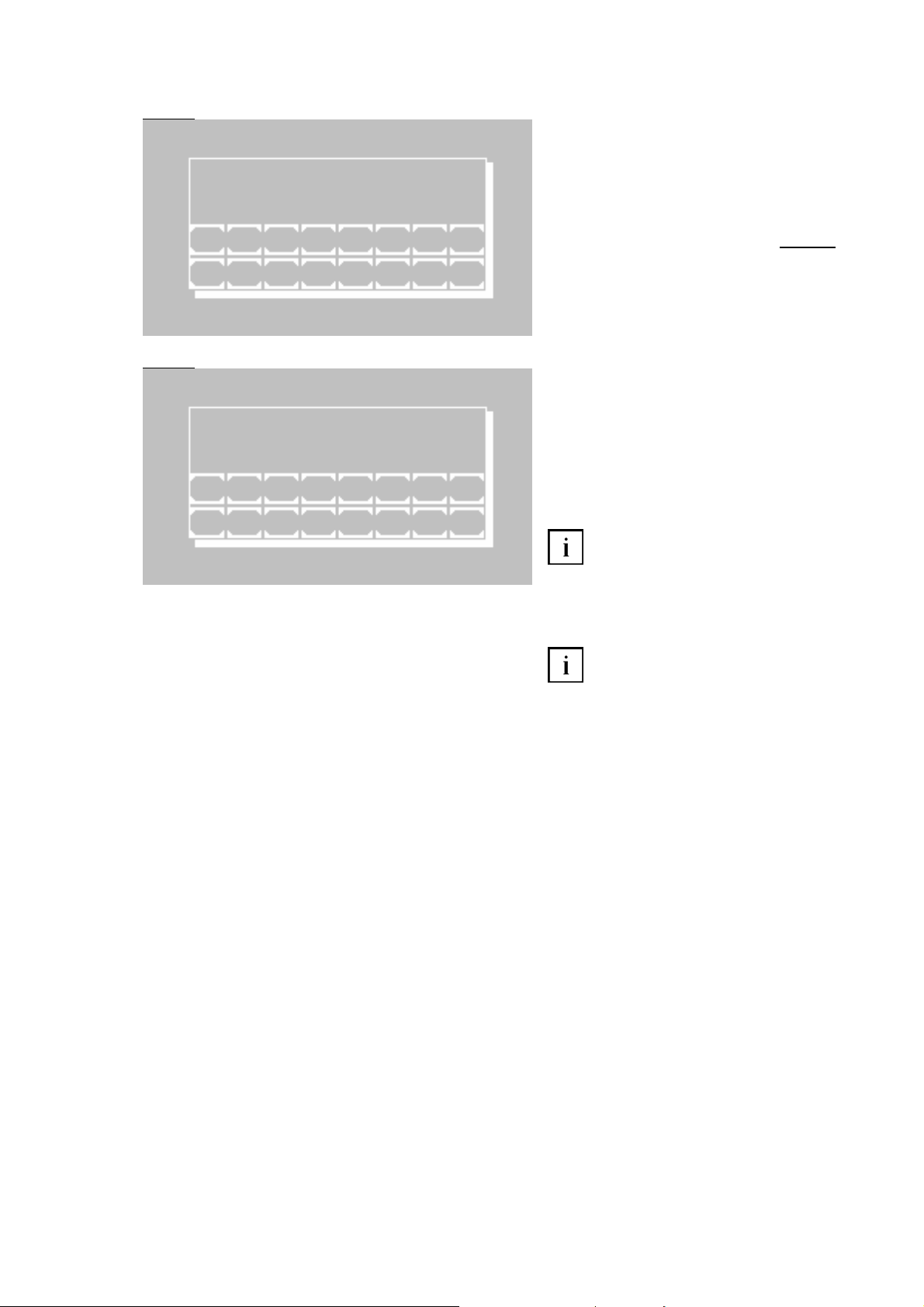
5010e_513.doc / 22.01.10
Fig. 6.7 Fig. 6.7
METHOD NO.
NEXT FREE NO. xx
1 2 3 4 5 6 7 8
ESC 9 0 . + - E
Fig. 6.8
CURVE NO. xx
P 1 A -00000 NEW A
C -00000
1 2 3 4 5 6 7 8
ESC 9 0 . P+ P-A/C E
Query of the desired method number, under
which the new method is to be stored. The
next free method number is indicated. However each free method number can be
selected within the range of 20 to 250.
[E] Store method with selected number. In
case of multi-standard method
Fig. 6.8
follows.
[ESC] Break storage and return to editor
menu
For a method with multi-standard there is the
editor window for the curve bases.
[P+] and [P-] Consecutive numbering of the
current bases
[A/C] Switch input between A for absorbance
and C for concentration
[E] Accept the edited value
Input and confirmation of a single “0” at
A lead to the deletion of the current pair of
points. In order to set the value to zero enter
e.g. “0.0”.
[ESC] End input and save curve data
For measuring in a multi-standard
method at least 2 bases with A and C must be
defined!
ROBERT RIELE GmbH & Co KG Page 42 6 - METHOD EDITOR D EDITOR

5010e_513.doc / 22.01.10
7 UTILITY PROGRAMS
7.1 SELECTION OF UTILITY PROGRAMS
MAIN MENU
MEASURE WITH PROGR. METHODS
MEASURE WITH BASIC METHODS
MEASURE NEW / CHANGE / COPY
UTILITIES LAMP LF
UTILITIES PAGE 1/5
DARK ADJUSTMENT PAGE
MULTI-STANDARD
PRINTER
PUMP MENU EXIT
37.05C 09/08/09 11:39
Utilities Description in
Main menu:
Utility programs are necessary for the adjustment and maintenance of the photometer.
37.05C 09/08/09 11:39
Page 1 of utility programs:
Scrolling through all utility programs is possible by [PAGE]. The current page is shown at
the right upper screen corner. By [EXIT] the
program returns to the main menu.
A utility program is selected by pressing the
relating key.
chapter
Dark adjustment 7.2.1
Multi-standard functions 7.2.2
Printer ON / OFF 7.2.3
Pump menu 7.2.4
Serial interface 7.2.5
Quality control 7.2.6
Settings printout 7.2.7
Data logging 7.2.8
Temperature ON / OFF 7.2.9
Temperature adjustment 7.2.10
Laboratory name 7.2.11
User name 7.2.12
Error list 7.2.13
Key signal ON / OFF 7.2.14
Touchscreen adjustment 7.2.15
Date / Time 7.2.16
Language 7.2.17
ADC counts (Optic) 7.2.18
Send results 7.2.19
Service tools 7.2.20
ROBERT RIELE GmbH & Co KG Page 43 7-
UTILITY PROGRAMS

5010e_513.doc / 22.01.10
7.2 DESCRIPTION OF UTILITY PROGRAMS
7.2.1 Dark adjustment
DARK ADJUSTMENT
EXIT START
The dark adjustment should be done not
before the warm-up time of 15 minutes has
passed, better after one hour operation.
To avoid strange light the lid has to be
closed during the dark adjustment.
Start the dark adjustment by [START].
DARK ADJUSTMENT
V 1 18235
PLEASE WAIT
Automatically all eight sensitivity levels
(V0...V7) are calibrated in succession at
simultaneous display of the dark value.
The function cannot be interrupted. After completion the program returns to the utility
program level.
Monthly executed the dark adjustment
compensates possible deviations of the
measuring accuracy due to environmental
influences.
ROBERT RIELE GmbH & Co KG Page 44 7- UTILITY PROGRAMS
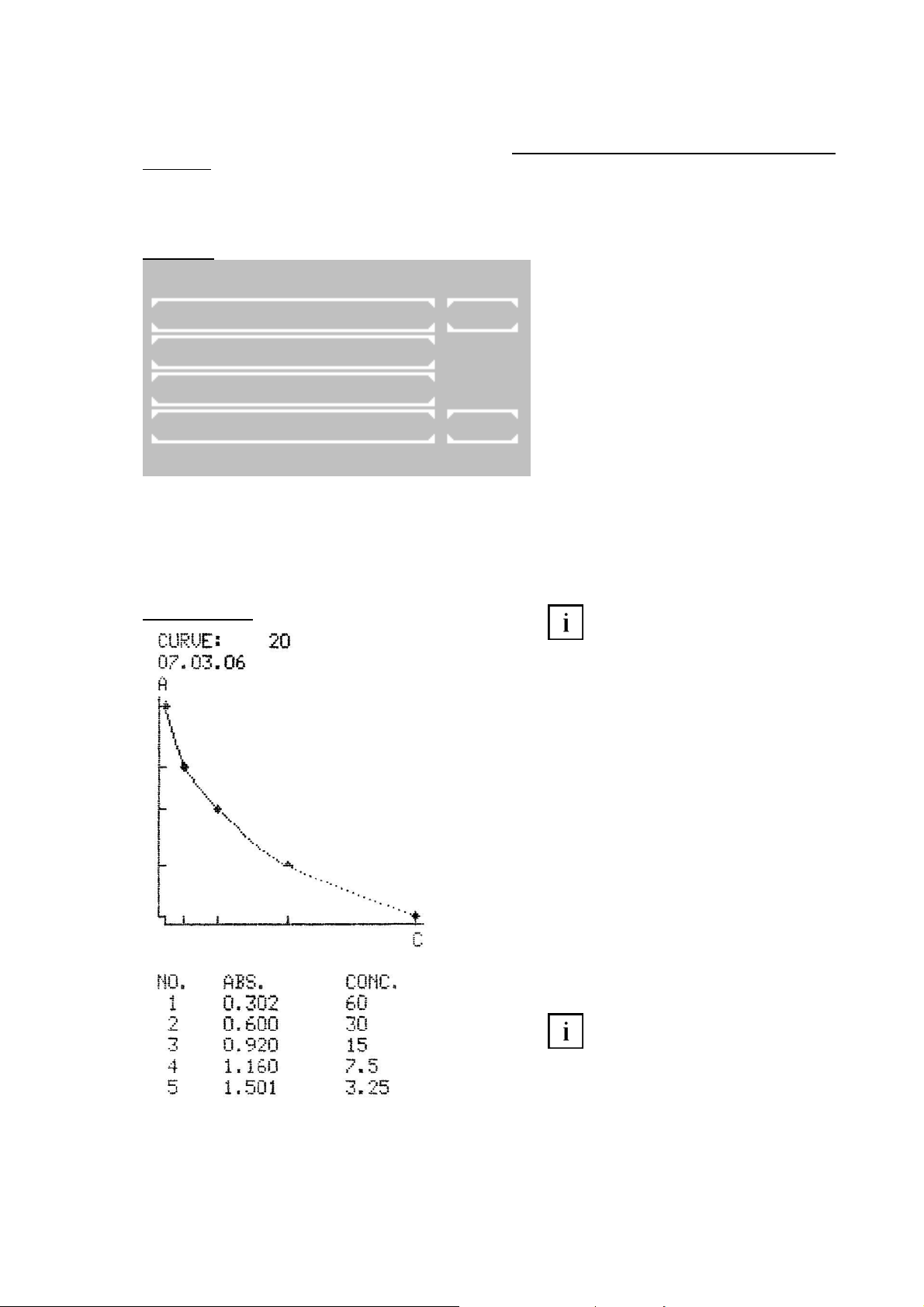
5010e_513.doc / 22.01.10
7.2.2 Multi-standard functions 7.2.2 Multi-standard functions
Before curve data of a method with multi-standard can be processed, the method must have been established
Before curve data of a method with multi-standard can be processed, the method must have been established
in the method editor (chapter 6 - METHOD EDITOR).
in the method editor (chapter 6 - METHOD EDITOR).
processed! The term “curve no” has the same meaning as “method no”.
If using a multi-standard method later on, pay attention that all extinction values of the samples lie within the
range of the curve bases. Values outside of the extinction range cannot be calculated. In this case “+-“ is shown
and “<<< >>>” printed instead of the reading.
Fig. 7.2.2.1
UTILITIES SUB MENUE
MEASURE CURVE LIST
PRINT CURVE
EDIT CURVE
SHOW CURVE EXIT
Print-out of curve:
A curve without corresponding method cannot be
A curve without corresponding method cannot be
Main window of multi-standard functions
[MEASURE CURVE] After query of a curve
number and the first standard the program
changes automatically to the method selection
window. There the given parameters of the
respective method can be again controlled
and/or changed. All further standards are
queried during the following procedure.
The program for measuring the multistandards branches out automatically to the
calculation procedures as follows:
37.05C 09/08/09 11:39
CP1 → CP5
CP2 → CP6
CP3 → CP7
CP4 → CP8
CP9 → CP10
CP11 → CP12
CP14 → CP14
For measuring in another standard
method than suggested, start measuring
multi-standards in each other selected
standard method (before measuring the first
standard) by [MODE]
[
MODE] [M-STD]. Curve
number and standards are queried
accordingly.
[MEASURE CURVE] After inquiry of a curve
number start of measuring of standard directly
with a basic method which is based on
standard. This special mode ends automatically after measuring or after selection of a
factor method. The standard of the selected
basic method represents the first standard
which can be measured. All further standards
are queried during the measuring execution in
the special mode.
[PRINT CURVE] After inquiry of the curve
number print-out on the internal printer or via
the serial interface.
For measuring in a multi-standard
method at least 2 bases with A and C must be
defined!
ROBERT RIELE GmbH & Co KG Page 45 7- UTILITY PROGRAMS Y PROGRAMS
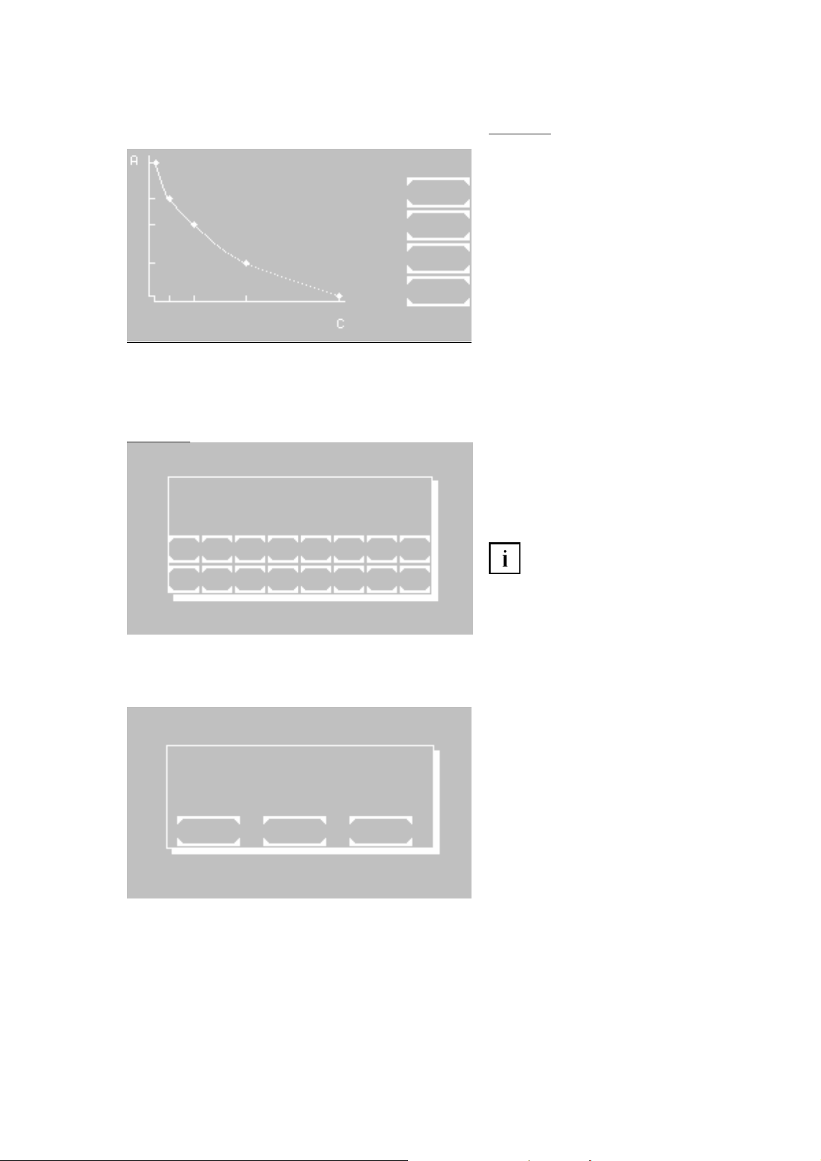
5010e_513.doc / 22.01.10
CURVE
NO. 20
EXIT
Fig. 7.2.2.2
CURVE NO. xx
P 1 A -00000 NEW A
C -00000
1 2 3 4 5 6 7 8
ESC 9 0 . P+ P-A/C E
7.2.3 Printer ON / OFF
PRINTER OFF
EXIT OK SELECT
[EDIT CURVE] After inquiry of the curve
[EDIT CURVE] After inquiry of the curve
number all curve bases can be edited (see
number all curve bases can be edited (see
fig. 7.2.2.2)
fig. 7.2.2.2).
[SHOW CURVE] After inquiry of the curve
number the function will be shown.
[LIST] The method number and the date of
preparation of all current curves are shown.
[EXIT] Return to the utilities
[P+] and [P-] Consecutive numbering of the
current bases
[A/C] Switch input between A for absorbance
and C for concentration
[E] Accept the edited value
Input and confirmation of a single “0” at
A lead to the deletion of the current pair of
points. In order to set the value to zero enter
e.g. “0.0”.
[ESC] End input and save curve data. The
bases are sorted in ascending order
according to their A value.
The current status of the internal printer is
indicated in the first line by OFF or ON.
Change setting by [SELECT]
Save setting permanently by [OK]
Save setting temporarily up to next switch-off
of the device by [EXIT]
ROBERT RIELE GmbH & Co KG Page 46 7- UTILITY PROGRAMS Y PROGRAMS
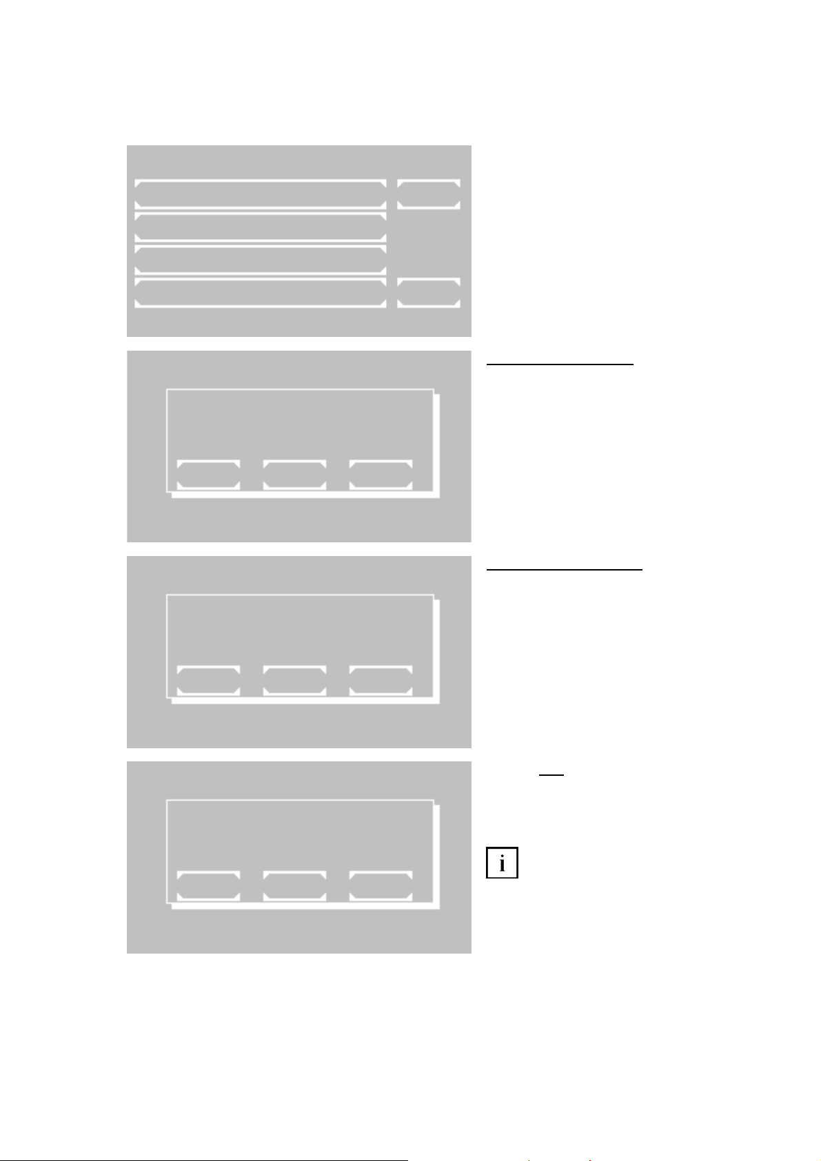
5010e_513.doc / 22.01.10
7.2.4 Pump menu 7.2.4 Pump menu
With these functions the pump and the bubble detector can be checked and adjusted. The check and adjust-
With these functions the pump and the bubble detector can be checked and adjusted. The check and adjustment is possible only with inserted flow-through cuvette adaptor.
ment is possible only with inserted flow-through cuvette adaptor.
UTILITIES SUB MENU
PUMP ON/OFF
PUMP CALIBRATION
PUMP SETTINGS
MEDIA TEST EXIT
PUMP ON
EXIT OK SELECT
The menu offers following functions:
• Activation and deactivation of pump
• Calibration of pump volume
• Activation and deactivation of bubble
detector and of the volume optimized
mode.
• Media test: check and adjustment of
bubble detector.
37.05C 09/08/09 11:39
7.2.4.1 Pump ON / OFF
The current status of the pump is indicated in
the first line by OFF or ON.
Change setting by [SELECT]
Save setting permanently by [OK]
Save setting temporarily up to next switch-off
of the device by [EXIT]
PUMP CALIBRATION
EXIT WASH
7.2.4.2 Pump calibration
The pump calibration can be executed with or
without bubble detector. So set bubble detector ON or OFF.
Empty aspiration tube by [WASH].
Put 1000 µl distilled water into a sample cup.
Dip aspiration tube into the sample cup up to
the base.
The volume of 1000 µl is sucked in by
[Sipping lever P].
PUMP CALIBRATION
AIR 159
WATER 1096
MS/50µl
EXIT OK WASH
Behavior
with bubble detector:
After stoppage of the pump values for air and
water are indicated which correspond to the
delivered volumes.
Save setting permanently by [OK]
If the calibration is not possible,
although the pump tube is connected and
1000 µl were sucked in, execute a media test
(see 7.2.4.4). Afterwards the pump calibration
can be repeated.
ROBERT RIELE GmbH & Co KG Page 47 7- UTILITY PROGRAMS Y PROGRAMS

5010e_513.doc / 22.01.10
PUMP CALIBRATION
AIR 159
WATER 1096
MS/50µl
EXIT OK WASH
Behavior
without bubble detector:
With each operation of [Sipping lever P] the
pump wheel rotates and delivers air. The turn
is shown beside the entry AIR on the screen.
As soon as the liquid in the tube between the
metal inlet tube and the screw connection of
the aspiration tube can be seen, confirm the
event by [OK].
During the second phase the system pumps
1000 µl distilled water by [Sipping lever P]
repeatedly.
The turn of the pump wheel is shown beside
the entry WATER. As soon as the end of the
liquid in the tube between the metal inlet tube
and the screw connection of the aspiration
tube can be seen, confirm the event by [OK].
Save setting permanently by [OK]
7.2.4.3 Pump settings
In this menu it is possible to configure the
bubble detector and the optimized volume
mode.
After configuring the bubble detector the
window for the configuration of the optimized
volume mode will be displayed automatically.
B-DET. ON
EXIT OK SELECT
7.2.4.3.1 Bubble detector ON / OFF
The current status of the bubble detector is
indicated in the first line by OFF or ON.
Change setting by [SELECT]
Save setting permanently by [OK]
Save setting temporarily up to next switch-off
of the device by [EXIT]
VOLUME OPTIMIZED ON
EXIT OK SELECT
7.2.4.3.2 Volume optimized ON / OFF
The current status of this setting is indicated in
the first line by OFF or ON.
Change setting by [SELECT]
Save setting permanently by [OK]
Save setting temporarily up to next switch-off
of the device by [EXIT].
When volume optimized is on, an acoustic
signal will be emitted after the required volume
is pumped. At this moment the sample must
be retired from the aspiration tube. After a
pause of approx. 1s the rest of liquid in the
tube will be completely pumped into the flow
through cuvette. For example, this function
makes it possible to pump two consecutive
times 500 µl from a 1000 µl sample volume.
ROBERT RIELE GmbH & Co KG Page 48 7- UTILITY PROGRAMS

5010e_513.doc / 22.01.10
MEDIA TEST
4 WATER 245
1 2 3 4 5 6 7 8
ESC 9 0 . + - E
7.2.4.4 Media test
With the media test the bubble detector can
be checked and adjusted.
In the second line to the left of the medium
WATER the current sensitivity level of the
bubble detector is shown.
Sip distilled water by [Sipping lever P]. Be
sure that the aspiration tube is completely
filled with water.
Enter new sensitivity level step by step by
numeric key [0] up to [7], starting with 0, until
the display changes from “AIR” to “WATER”.
Then increase the sensitivity level by one
further step.
Empty the aspiration tube by [Sipping lever P].
The display changes from “WATER” to “AIR”.
The adjustment is permanently saved by [E].
ROBERT RIELE GmbH & Co KG Page 49 7- UTILITY PROGRAMS

5010e_513.doc / 22.01.10
7.2.5 Serial interface 7.2.5 Serial interface
A PC or an external printer can be connected to Photometer 5010 via the RS 232 serial interface at the back. A
A PC or an external printer can be connected to Photometer 5010 via the RS 232 serial interface at the back. A
suitable data cable can be supplied (REF 501-002). The connected device must comply with safety standard
suitable data cable can be supplied (REF 501-002). The connected device must comply with safety standard
EN 60950.
EN 60950.
UTILITIES SUB MENU
EDP ON / OFF
REMOTE MODE
SERIAL PRINTER
DOWNLOAD EXIT
EDP OFF
EXIT OK SELECT
The menu offers following functions:
• Activation and deactivation of EDP
• Activation of remote control
• Activation or deactivation of external
printer with serial interface
• Activation of download function of oper-
ating system
37.05C 09/08/09 11:39
7.2.5.1 EDP ON / OFF
The current status of the EDP (Electronic Data
Processing) interface is indicated in the first
line by OFF or ON.
Change setting by [SELECT]:
• EDP OFF: no output,
• EDP ON (CR-LF): system output through
serial port with CR-LF protocol,
• EDP ON (STX-ETX-BCC): system output
through serial port with STX-ETX-BCC
protocol,
• EDP ON (CR-LF-LOG): after each
measurement a formatted string will be
output through the serial port. (e.g. see
table. 7.2.5.1)
Save setting permanently by [OK]
Save setting temporarily up to next switch-off
of the device by [EXIT]
Table 7.2.5.1
Serial number Method number ID-NO. Sample number Result User Date Time
7000 20 12345 1 15.5 [user name] 09/08/09 09:30
REMOTE MODE
EXIT START
7.2.5.2 REMOTE CONTROL
Activate remote control by [START].
When activated, Photometer 5010 can be
remote-controlled by a PC and a suitable
program.
Deactivate remote control by sipping lever [P].
By [EXIT] the program returns to the
superordinate menu item.
ROBERT RIELE GmbH & Co KG Page 50 7- UTILITY PROGRAMS Y PROGRAMS

5010e_513.doc / 22.01.10
SERIAL PRINTER OFF
EXIT OK SELECT
DOWNLOAD PLEASE WAIT
7.2.5.3 SERIAL PRINTER ON / OFF
The current status of the external serial printer
is indicated in the first line by OFF or ON.
Change setting by [SELECT]
Save setting permanently by [OK]
Save setting temporarily up to next switch-off
of the device by [EXIT]
7.2.5.4 DOWNLOAD
The operating system of Photometer 5010 is
contained in an electronically erasable and
programmable FLASH MEMORY. With the
download function the operating system of the
Photometer 5010 can be updated by PC.
The download function is controlled by an
appropriate software and terminated after
actualization.
A break of the function cannot be accomplished by key. Only switching the photometer
off terminates the download function.
7.2.6 Quality control
In Photometer 5010 up to 50 methods can be supervised with a quality control. The device can manage up to 6
control serums. Each QC supervised method can be connected with 2 control serums. The QC data of a series
of measurements are stored in a daily memory. Each reading is stored with method number, date and user
identification. From the daily memory the individual QC data can become deleted or saved in the monthly
memory of the corresponding method. The monthly memory of a QC method can record up to 31 readings. With
the 32nd the oldest reading is deleted in the memory. For the calculation of the quality values of a method at
least 20 readings in the monthly memory must be present. The average of all readings, the standard deviation
and the coefficient of variation are calculated. Contents of the daily and monthly memory can be indicated and
printed out.
Except the basic methods all methods can be connected with a quality control. The method-typical data of a
control serum are entered via the method editor (see chapter 6 METHOD EDITOR).
UTILITIES SUB MENUE
EDIT CONTROL SERUM
DAILY MEMORY
MONTHLY MEMORY
QC EDP EXIT
37.05C 09/08/09 11:39
The QC menu offers following functions:
[EDIT CONTROL SERUM] Up to 6 control
serums can be defined.
Without a defined
serum the QC cannot be started!
[DAILY MEMORY] View, print and processing of the daily memory for serum 1/2
[MONTHLY MEMORY] View, print and processing of the monthly memory for serum 1/2
[QC EDP] - not implemented -
ROBERT RIELE GmbH & Co KG Page 51 7- UTILITY PROGRAMS
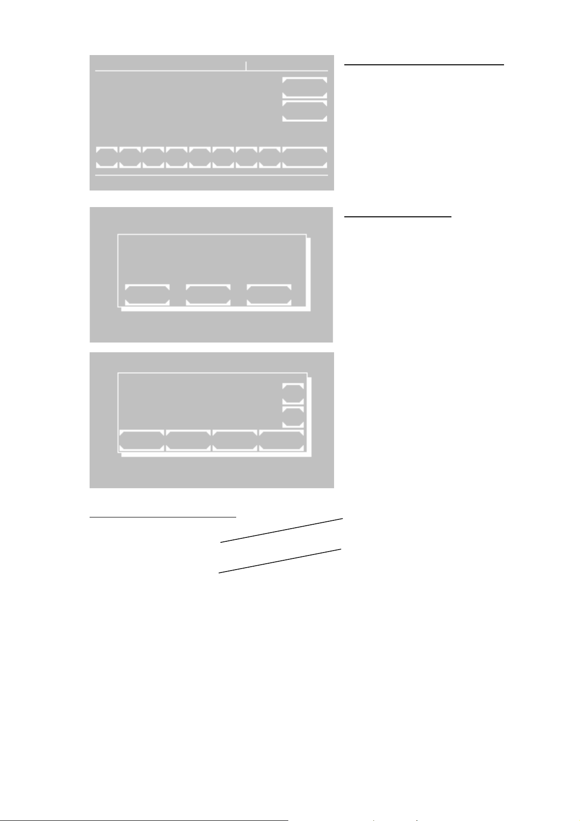
5010e_513.doc / 22.01.10
CONTROL SERUM 1
1-ID
2- EXIT
3-LOT
45-COMPANY OK
67-DATE
8-
1 2 3 4 5 6 7 8 NO.
SELECT MEMORY
EXIT S1 S2
7.2.6.1 INPUT OF CONTROL SERUM
[1] Enter name max 15-digit
[3] Enter LOT no max 10-digit
[5] Enter company max 10-digit
[7] Enter expiry date max 8-digit
[NO.] Change to next control serum
[EXIT] and [OK] Accept input and return to
37.05C 09/08/09 11:39
QC menu
7.2.6.2 DAILY MEMORY
[S1] Select daily memory for serum 1
[S2] Select daily memory for serum 2
[EXIT] Return to previous window
DAILY MEMORY S1
+
25 GLUCOSE
13.03 mmol/l -
EXIT DEL. STORE PRINT
Measuring data of the corresponding daily
memory are shown with method number,
method name, reading and dimension.
[+] Change to next reading
[-] Change to previous reading
[DEL] Delete shown reading in the daily
memory and confirm again by [DEL]
[STORE] Store shown reading in the daily
memory and confirm again by [STORE].
Print-out of daily memory for serum 1:
*** DAILY MEMORY ***S1 *
PHOTOMETER 5010 #7000
Afterwards the reading is deleted in the daily
memory.
[PRINT] Print all readings
[EXIT] Return to QC menu
V5.13a 02/09/09 D
LAB.: RIELE GMBH+CO KG
DATE: 09/08/09
TIME: 08:30:03
25 GLUCOSE 13.03
21 HDL-C 367
27 UREA COL 197.2
29 CK-MB 1128.1
31 GOT 189.9
ROBERT RIELE GmbH & Co KG Page 52 7-
UTILITY PROGRAMS

5010e_513.doc / 22.01.10
CONTROL SERUM
EXIT S1 S2
7.2.6.3 MONTHLY MEMORY
After query of method number select serum 1
or 2 of the method.
[S1] Select monthly memory for serum 1
[S2] Select monthly memory for serum 2
[EXIT] Return to previous window
MONTHLY MEMORY S2
METHOD 25 GLUCOSE
SERUM 1 LT-SYS abnormal
LOT G312
COMPANY LABOR+TECH
DATE MAY 06
REQUIRED 14.4 mmol/l
RANGE L: 12.1 O: 16.7
CALCUL. s: 1.012 VK: 7.298
m: 13.860 n: 20
# 1 07.09.07 13.30 -1s 1
EXIT MORE DELETE - +
In the overview window of the selected
method all data of quality control are visible. In
the line above the keys following information
the current reading is indicated:
(# 1) → Numerator of the monthly memory.
The oldest reading corresponds to the 1.
(01.27.06) → Date of reading
(13.30) → Reading
(-1.s) → Deviation of the reading lies within
minus 1s. From +/-3s the warning level starts.
With a deviation of > 3s an * is displayed. For
the calculation of the quality values of a
method at least 20 readings in the month
memory must be present!
(1) → User identification
The keys have following functions:
[+] Change to next reading
[-] Change to previous reading
[DEL] Delete
all measuring data of the
monthly memory of the selected method and
confirm again (e.g. at change of serum)
[MORE] Change to output dialog
[EXIT] Return to QC menu
ROBERT RIELE GmbH & Co KG Page 53 7- UTILITY PROGRAMS

5010e_513.doc / 22.01.10
PRN-N
PRN-E
EXIT
Printout of the monthly memory of a method with serum 2:
** MONTHLY MEMORY **S2 *
DATE: 09/08/09
PHOTOMETER 5010 #7000
V5.13a 02/09/09 D
LAB.: RIELE GMBH+CO KG
METHOD 25: GLUCOSE
UNIT: mmol/l
SERUM NO. 5
ID LT-SYS abnormal
LOT G312
COMPANY LABOR+TECH
DATE MAY 06
REQUIRED 14.4
MIN.VALUE 12.1
MAX.VALUE 16.7
QC VALUES n: 20
MEAN m: 13.860
STD.DEVIATION s: 1.012
COEFF.OF VAR CV: 7.298
Output dialog
If at least 20 readings are stored in the
monthly memory, these are indicated in the
Levey Jennings plot. In this representation the
deviations can be controlled visually and thus
tendencies or systematic errors be better
recognized.
The keys for the printout are located next to
the curve diagram:
[PRN-N] Start the normal printout of the data
of the current monthly memory. The single
data of the readings are not printed thereby.
[PRN-E] Start the extended printout of the
data of the current monthly memory. As
shown in the example left, also the single data
of the readings are printed.
[EXIT] Return to QC menu
02.15.06 13.54 -1s 1
02.14.06 14.07 +1s 1
02.13.06 14.69 +1s 1
02.12.06 13.50 -1s 3
02.11.06 14.68 +1s 3
02.10.06 15.33 +2s 1
02.09.06 15.99 +3s 1
02.08.06 15.38 +2s 2
02.07.06 14.61 +1s 1
02.06.06 13.70 -1s 1
02.05.06 12.74 -2s 1
02.04.06 12.13 -2s 1
02.03.06 12.65 -2s 2
02.02.06 13.11 -1s 1
02.01.06 13.88 +1s 3
01.31.06 13.51 -1s 3
01.30.06 13.24 -1s 3
01.29.06 12.50 -2s 1
01.28.06 12.74 -2s 2
01.27.06 13.30 -1s 1
ROBERT RIELE GmbH & Co KG Page 54 7- UTILITY PROGRAMS Y PROGRAMS

5010e_513.doc / 22.01.10
Not implemented Not implemented
7.2.7 Settings printout
SETTINGS PRINTOUT
EXIT START
7.2.6.4 QC EDP7.2.6.4 QC EDP
By [START] the program version and the
complete status of the saved settings are
printed out.
******ACTUAL*SETS*******
DATE: 09/08/09
TIME: 12:59:51
PHOTOMETER 5010 # 7000
V5.13a 02/09/09 D /2.0
PCB LAYOUT d
ADC COUNTS(DARK ADJ.) E
0: 18240 1: 18244
2: 18251 3: 18261
4: 18279 5: 18312
6: 18380 7: 18494
ADC COUNTS(DARK ADJ.) D
0: 18235 1: 18236
2: 18236 3: 18237
4: 18240 5: 18246
6: 18255 7: 18271
TEMPERATURE E
25C 8322 3000
30C 9552 3000
37C 11273 3000
TEMPERATURE D
25C 8299 3000
30C 9485 3000
37C 11165 3000
FILTER
0: DDD 1: 340
2: 405 3: 492
4: 546 5: 578
6: 623 7: 999
8: 999 9: 999
PUMP
MS AIR 201
MS/50ul 66
B-DET. 5
VOLUME OPTIMIZED OFF
BATTERY: OK
VDC LAMP 12.12V
ADC CORRECTION 150
STACK TEST 14
BOOST nm 390
EDP OFF (STX-ETX-BCC)
LANUAGE
1: ENGLISH
2: GERMAN
KEY SIGNAL ON
PROGR. METHODS 0
ROBERT RIELE GmbH & Co KG Page 55 7- UTILITY PROGRAMS Y PROGRAMS

5010e_513.doc / 22.01.10
7.2.8 Data logging 7.2.8 Data logging
Up to 2970 results can be managed in the memory of Photometer 5010. They are stored together with a two
Up to 2970 results can be managed in the memory of Photometer 5010. They are stored together with a two
digit identification number, which can be assigned e.g. to a patient or to a sample. The range of the identification
digit identification number, which can be assigned e.g. to a patient or to a sample. The range of the identification
number starts with 1 and ends with 99. Up to 2970 results can be assigned to one identification number or aver-
number starts with 1 and ends with 99. Up to 2970 results can be assigned to one identification number or average 30 results for maximum 99 identification number stored.
age 30 results for maximum 99 identification number stored.
Memory contents remain after switching the device off. If the memory is filled with 2970 results, no further result
Memory contents remain after switching the device off. If the memory is filled with 2970 results, no further result
can be added. The memory must be emptied first by deletion of results.
can be added. The memory must be emptied first by deletion of results.
UTILITIES SUB MENUE
LOGGING ON/OFF
PRINT DATA OF ID-NO.
DELETE DATA OF ID-NO.
REPORT OF LOG. MEMORY EXIT
Print-out of readings of an ID no:
*** DATA FROM ID-NO. ***
PHOTOMETER 5010 #7000
DATE: 09/08/09
LAB.: RIELE GMBH+CO KG
ID-NO.: 35
DATE: 09/08/09
METHOD 24: GLUCOSE
13.03 mmol/l
DATE: 09/08/09
METHOD 25: CK-MB
195 U/l
DATE: 09/08/09
METHOD 24: GLUCOSE
12.17 mmol/l
Report of logging memory :
**** LOGGING REPORT ****
PHOTOMETER 5010 #7000
DATE: 09/08/09
5/ 3 11/ 2 14/ 2
35/ 3
The logging menu offers following options:
[LOGGING ON/OFF] Activation of data logging. If this mode is activated, the sample
numerator gets a new function as ID no. Then
before each measuring the numerator must be
set to the required number between 1 and 99
by [MODE] and [NUM]. After each measuring
the reading is asked to be stored.
[PRINT DATA OF ID-NO.] After query of the
37.05C 09/08/09 11:39
ID no the corresponding readings are printed
out. Afterwards the printed data are asked to
be deleted.
[DELETE DATA OF ID-NO.] After query of
the ID no the corresponding readings are
deleted.
[REPORT OF LOG. MEMORY] Print-out of a
report of the complete logging memory with ID
no and corresponding number of readings,
e.g.:
5/ 3 stands for 3 stored readings for ID no 5.
[EXIT] Return to the utilities.
ROBERT RIELE GmbH & Co KG Page 56 7- UTILITY PROGRAMS Y PROGRAMS

5010e_513.doc / 22.01.10
7.2.9 Temperature ON / OFF 7.2.9 Temperature ON / OFF
TEMPERATURE ON D
OFF
25C
30C
37C
EXIT OK SELECT
7.2.10 Temperature adjustment
The current status of the tempering is indicated in the first line by OFF or ON. Besides
the inserted cuvette adaptor is marked by D or
E.
Change setting by [SELECT]. Following
options are possible:
• OFF
• 25° C
• 30° C
• 37° C
Save setting permanently by [OK].
Save setting temporarily up to next switch-off
of the device by [EXIT].
TEMP. ADJUSTMENT
TEMP. ACTUAL : 36.90
1 2 3 4 5 6 7 8
ESC 9 0 . + - E
The temperature control was
adjusted at the factory!
Anyhow the tempering control can be calibrated provided that the tempering was
switched on for at least 30 minutes:
Measure the current temperature with an
independent measuring system (e.g. thermistor, REF 090-063) inside the cuvette and enter
this value. According to the difference to 25.0
°C, 30.0 °C or 37.0 °C the system corrects its
internal setting. The calibrating of the temperature is interrupted when the tempering is
off or the temperature unstable.
Enter the password “5010”.
Enter the actual temperature in TEMP.
ACTUAL
four-digit in °C (e.g. 36.90) and
confirm by [E].
ROBERT RIELE GmbH & Co KG Page 57 7- UTILITY PROGRAMS Y PROGRAMS

5010e_513.doc / 22.01.10
7.2.11
7.2.11
Laboratory name
Laboratory name
LABORATORY NAME
EXIT NEW
The name of the laboratory can be stored
permanently.
In case of a stored name an additional line
within the header is sent to the printer or to the
EDP.
By [NEW] the entry of the laboratory name is
possible.
UTILITIES PAGE 3/5
NEW LABORATORY NAME
<
Q W E R T Y U I O P
A S D F G H J K L Å
ESC Z X C V B N M A/1ENT
7.2.12 User name
USER NAME
1:
2:
3:
4:
5:
EXIT NEW SELECT
Enter the laboratory name via the alphanumeric keyboard.
Following functions are available:
• [a/1] : change to lowercase
• [1/A] : change to numeric characters
• [A/a] : change to uppercase
• [Å] : delete character
• [Æ] : blank
• [ESC] : finish input without storage
• [ENT] : finish input with storage
The names of maximum five users can be
stored permanently.
After calling a method the user is queried.
In case of a stored name an additional line
within the header is sent to the printer or to the
EDP.
Select user by [SELECT]. By [NEW] the entry
of the user name is possible.
UTILITIES PAGE 3/5
NEW USER NAME 1
<
Q W E R T Y U I O P
A S D F G H J K L Å
ESC Z X C V B N M A/1ENT
Enter the user name via the alphanumeric
keyboard.
Following functions are available:
• [a/1] : change to lowercase
• [1/A] : change to numeric characters
• [A/a] : change to uppercase
• [Å] : delete character
• [Æ] : blank
• [ESC] : finish input without storage
• [ENT] : finish input with storage
ROBERT RIELE GmbH & Co KG Page 58 7- UTILITY PROGRAMS Y PROGRAMS

5010e_513.doc / 22.01.10
7.2.13 Error list 7.2.13 Error list
ERROR LIST
NO. 1
DATE 09/08/09
ERROR CODE 46
EXIT PRINT NEXT
7.2.14 Key signal ON / OFF
KEY SIGNAL ON
EXIT OK SELECT
The last 10 serious errors are shown or
printed.
The oldest error is shown first. The last error is
always marked with no 1.
By [NEXT] earlier error messages are shown.
By [PRINT] the complete error list is printed or
output to the serial interface.
For troubleshooting the coded error list can be
consulted (chapter 9.4 - CODED ERROR
MESSAGES).
The current status of the key signal is indicated in the first line by OFF or ON.
Change setting by [SELECT].
Save setting permanently by [OK].
Save setting temporarily up to next switch-off
of the device by [EXIT].
The deeper signal tone for error messages
remains active in any case.
7.2.15 Touchscreen adjustment
X 0 Y 0
TOUCH PANEL ADJUSTMENT
PRESS EXACTLY THE CROSSPOINT
TIME 10
SAVE TP ADJUSTMENT
EXIT OK
By this function the panel can be adjusted.
After call of the function a white cross is
shown in the left lower corner of the screen.
Touch the intersection point in the cross with a
non-scratching plastic tip (touchscreen pen,
pipette tip) as exactly as possible. In the first
line the coordinates are shown as X- and Yvalue. The input will be accepted and the
coordinate display will be reset after a time out
of 10s. Then the cross is shown in the right
upper corner. Touch the intersection point.
After a timeout of 10s the memory inquiry
follows.
Save the adjustment by [OK].
Reject the adjustment by [EXIT].
ROBERT RIELE GmbH & Co KG Page 59 7- UTILITY PROGRAMS Y PROGRAMS
5010e_513.doc / 22.01.10
HintHint: If the device is maladjusted, this function can directly be called during the switching on routine:
Keep the touchscreen pressed during switching on. After some seconds a deep signal tone sounds and the text
message “TOUCH PANEL ADJUSTMENT” will be shown at the first line of the greeting screen. Release the
touchscreen within one second. Execute the adjustment of the touchscreen as described above. You must
choose your Photometer type (4040 or 5010) after the touchpanel adjustment is completed.
SELECT PHOTOMETER
4040 5010
Select Photometer:
This dialog will be only displayed when the
touchscreen adjustment has been entered
during switching on the Photometer.
The Photometer type in use must be selected:
4040 or 5010.
7.2.16 Date / Time
DATE / TIME ON
EXIT OK SELECT
DATE TIME
mm/dd/yy hh:mm:ss
09/08/09 15:35:00
1 2 3 4 5 6 7 8
ESC 9 0 . + - E
The current status of the date/time display is
indicated in the first line by OFF or ON.
Change setting by [SELECT].
With activation of the clock date and time can
be changed by [OK]. Each entry of day,
month, year, minute and second must be
confirmed by [E].
If a value is to be changed, then all
values are to be entered again!
7.2.17 Language
LANGUAGE : ENGLISH
EXIT OK SELECT
The current status of the language is indicated
in the first line.
The setting can be changed by [SELECT]
Following options are possible:
• LANGUAGE : ENGLISH
• LANGUAGE : GERMAN
Save setting permanently by [OK].
The setting is temporarily saved up to next
switch-off of the device by [END].
ROBERT RIELE GmbH & Co KG Page 60 7- UTILITY PROGRAMS Y PROGRAMS

5010e_513.doc / 22.01.10
7.2.18 ADC counts (Optic) 7.2.18 ADC counts (Optic)
UTILITIES PAGE 5/5
ADC COUNTS (OPTIC)
BOOST OFF
V0 F1 340 nm 21336
V0 V1 V2 V3 V4 V5 V6 V7 BO.
F0 F1 F2 F3 F4 F5 F6 F7 F8 F9
ESC
7.2.19 Send results
SEND RESULTS
EXIT START
Indicated is the current value of the optical
analogue-digital converter. The value is
proportional to the light-current depending on
the selected amplification level and the boost
setting.
To a key actuation the system reacts possibly
nly after three seconds.
o
The functions V0 to V7 set the amplification
level. The function BO increases (boost ON)
or reduces (boost OFF) the time slot. The
functions F0 to F9 place the filter wheel into
the positions 0 to 9. The position 0 corresponds to the filter wheel position at the dark
adjustment.
Stop function by [ESC].
Start sending stored results through the serial
port by pressing [START] or cancel with
[EXIT].
After sending is completed you will be
prompted to delete stored results. Press
[START] to delete results or [EXIT] to exit
without deleting results.
7.2.20 Service tools
SERVICE TOOLS
PASSWORD
1 2 3 4 5 6 7 8
ESC 9 0 . + - E
The service tools are reserved for trained
specialists only and therefore protected by a
password.
Stop function by [ESC].
ROBERT RIELE GmbH & Co KG Page 61 7- UTILITY PROGRAMS Y PROGRAMS

5010e_513.doc / 22.01.10
8 MAINTENANCE
This chapter provides necessary information concerning general maintenance by the user.
If any faults should occur which cannot be remedied, then service should be contacted. Repairs at the
device may be carried out only by authorized specialist staff. Through improper repairs the warranty extinguishes, and the user can be heavily jeopardized.
8.1 CLEANING INSTRUCTION
Liquid waste is potentially biologically hazardous. Always wear gloves if handling those materials. Do not
touch parts of the device other than those specified. Consult the laboratory protocol for handling biohazardous
materials.
Take care that no liquid enters the device! There is no protection against penetrating of liquids
(Code IP X0). Check from time to time that the tubing and the connections are leakproof.
The flow-through system of the Photometer 5010 has to be washed with dist. water regularly before and after
measuring 2 – 3 times. Depending on sample material and reagent, and always at the end of a working day, the
Photometer 5010 has to be cleaned additionally with a phosphate-free detergent, e.g. with approx. 5ml of
Biogent-A (REF 5010-024), and afterwards rinsed with 5ml distilled water.
Persistent residues are to be removed with a combined alkaline-acid treatment. The following procedure is
advised step by step:
1. 5 x wash with NaOH 1 N
2. 5 x rinse with dist. water
3. 5 x wash with HCl 0.5 N
4. 5 x rinse with dist. water
If the system is contaminated severely, it may alternatively be cleaned with hypochlorite. The following procedure is advised step by step:
1. 5 x rinse with dist. water
2. 2 – 3 x wash with hypochlorite (1:20 diluted solution) or ISE Cleaning Solution,
undiluted, let it possibly affect up to 20 minutes
3. 5-10 x rinse with dist. water
For device cleaning and surface decontamination purposes use commercial decontaminating solution which are
usually available in clinical chemistry laboratories like Mikrozid
similar solutions. Switch off the device and disconnect it from the mains voltage. Then clean the device with soft
cloth and decontaminating solution.
Empty the drain tank at the end of daily measurement, or whenever filled.
®
AF Liquid, Bacillol® plus, 3 % Kohrsolin® or
8.2 CALIBRATING MEASURING SYSTEM
At doubtful measurement results a dark adjustment has to be carried out corresponding to chapter 7.2.1.
8.3 ADJUSTMENT OF BUBBLE DETECTOR
See chapter 7.2.4 - Pump
8.4 CALIBRATION OF PERISTALTIC PUMP
See chapter 7.2.4 - Pump
8.5 REPLACEMENT OF RIBBON
Open printer cover. Lift used ribbon by pressing “PUSH” on the left. Take ribbon cassette out of the printer.
Take new ribbon cassette out of the wrapping. Turn small wheel on the left in the direction marked by an arrow
till the inked ribbon is tightened.
Put in the ribbon cassette. Pay attention that the paper is to be taken through inked ribbon and cassette. Take
printer paper through the crack of the printer cover and close the printer cover.
ROBERT RIELE GmbH & Co KG Page 62 8 -
MAINTENANCE

5010e_513.doc / 22.01.10
8.6 REPLACEMENT OF PAPER ROLL
See chapter 2.4 - LOADING PRINTER PAPER
8.7 REPLACEMENT OF ASPIRATION TUBE
When replacing the aspiration tube pay attention to the sequence of the assembly parts as shown below. Then
put aspiration tube without bending from the cuvette area side through the metal inlet tube. Turn screw connection with fingers into the cuvette.
inlet tube with base
screw connection, milled O-ring washer
8.8 REPLACEMENT OF LINE FUSES
The Photometer 5010 operates at any line voltage between 90 V
It has two line fuses in series with the power supply. They are located on the rear panel. To replace those fuses,
unplug the mains cable and remove the fuse holder with the fuses as shown below. The instrument is delivered
with two spare fuses.
Neither use makeshift fuses nor short-circuit the fuse holder!
Specifications of mains fuse:
• dimensions [mm] : 5 * 20
• standard: IEC 60127-2/V
• time-current characteristic: time lag (T)
• voltage rating: 250 V
• rated current: 1.6 A
• marking: T 1.6 A H
and 264 VAC at 50/60 Hz without adjustment.
AC
mains switch
ROBERT RIELE GmbH & Co KG Page 63 9 -
fuse holder
mains cable connector
ERROR MESSAGE / CORRECTION

5010e_513.doc / 22.01.10
9 ERROR MESSAGE / CORRECTION
9.1 GENERAL NOTE
Faulty input (e.g. wrong method number or wrong factor), recognized by the user, can be corrected by filling up
the respective entry field with any signs. After replenishing beyond the last position the faulty input is deleted
and the entry field is free again for the renewed correct input.
Error messages by the device are carried out either exclusively via a signal tone (chapter 9.2 - ACOUSTIC
ERROR MESSAGES) or as combination signal tone and display.
In the display errors are shown as plaintext (chapter 9.3 - PLAINTEXT ERROR MESSAGES)
… or coded with an error number (chapter 9.4 - CODED ERROR MESSAGES).
Each error message has always to be confirmed with [E].
9.2 ACOUSTIC ERROR MESSAGES
When pressing a key which is not permitted or not meaningful a deeper signal tone still sounds as error
message after the higher signal tone (which is to confirm the keystroke, can be switched off according to
chapter 7.2.14 - Key signal ON / OFF). In the display
The operation of the device can directly be continued by the correct keyboard entry.
no corresponding error message appears parallel to this.
9.3 PLAINTEXT ERROR MESSAGES
RANGE MIN. The programmed low limit was under-run by the measurement.
RANGE MAX. The programmed upper limit was exceeded by the measurement.
RANGE R^2 The square of the correlation coefficient R lies at the kinetic measuring below the
programmed low limit.
RANGE +/- At the kinetic measuring the procedure of the kinetic is wrong (increasing / falling).
NO METHOD Dialed method is not programmed. Select other method according to method list.
HEATING OFF Heating / cooling is off during temperature calibration.
TEMP. UNSTABLE Temperature is unstable during temperature calibration.
9.4 CODED ERROR MESSAGES
No. (possible) Causes Remedy
1 method is write protected, method cannot be cleared by special software
2 check sum of a freely programmed method is wrong program new method
3 forbidden input, wrong number format repeat input in permitted area
4 method not available method editor:
5 dark value is absolutely too high (> 16 bit) or higher as the
measurement,
ADC overflow
6 all multiplexer positions are too bright/too dark at setting to
zero
7 mathematical overflow, at measurement calculation check filter; check standard;
ROBERT RIELE GmbH & Co KG Page 64 9 -
check method no.
repeat dark adjustment;
check lamp / filter; check blank
repeat dark adjustment;
check filter / lamp; check blank
check measuring solution
ERROR MESSAGE / CORRECTION

5010e_513.doc / 22.01.10
8 check sum error in the data record of the dark offset repeat dark adjustment
9 check sum error in the data record of the device basic
automatic error remedy
setting (status, ADC correction)
10 division by a too small value (< 0.001 A) check filter; check standard;
check measuring solution
11 invalid calibration curve Select valid number
12 setting to zero not possible (zero value is < 32768 cycle) check lamp; check filter;
check zero solution
13 setting to zero not possible (zero value is > 983039 cycle) check lamp; check filter;
check zero solution
14 invalid standard measure valid standard solution
15 no parameter memory vacant (too little memory for non-
linear methods)
delete a no longer actual
method
nonlinear
16 method no. is occupied select other method no.; delete a no
nonlinear method
17 check sum error in the parameter memory (nonlinear
longer actual
program method newly
method)
18 at calculation overflows in nonlinear method check factor; check parameter
19 clock malfunction
20 overflow at Kinetic check measuring solution
21 overflow at Kinetic check measuring solution
22 overflow at Kinetic check measuring solution
23 overflow at Kinetic check measuring solution
24 overflow at Kinetic check measuring solution
25 overflow at Kinetic check measuring solution
26 overflow at Kinetic check measuring solution
27 overflow at Kinetic check measuring solution
28 overflow at Kinetic check measuring solution
29 wrong input of deltas or time per delta restart method
30 battery empty contact service partner
31 communication: wrong data format contact service partner
32 communication: sent data not plausible / not interpretable contact service partner
33 communication: mentioned module does not answer in a
certain time
check interconnecting cable;
check mentioned module
34 communication: overflow send/receive buffer reduce amount of data at the
communication partner
35 remote control: wrong method number external software problem
36 remote control: unknown command external software problem
37 remote control: wrong data format external software problem
38 check sum of operating system bank 0 damaged contact service partner
39 check sum of operating system bank 1 damaged contact service partner
40 timeout at reception from module 2 switch off/on device
41 check sum error at reception from module 2 switch off/on device
42 NAK at reception from module 2 switch off/on device
ROBERT RIELE GmbH & Co KG Page 65 9 - ERROR MESSAGE / CORRECTION

5010e_513.doc / 22.01.10
44 error at pump calibration
- pump tube not clamped;
- no liquid aspirated;
- too much liquid aspirated during calibrating;
- power of the pump too small;
- motor does not rotate or stops;
- connectors of tubes leaky;
- bubble detector works falsely;
- aspiration tube blocked;
- clamp pump tube;
- control volume of aspiration;
- control connectors of tubes;
- the plug of the bubble detector has a bad
contact;
- the cable of the bubble detector has a
bad contact;
- adjust bubble detector (chapter 7.2.4);
- replace aspiration tube (chapter 8.7)
- aspiration tube badly stained
45 error at sipping solution
- pump tube not clamped;
- no liquid aspirated;
- power of the pump too small;
- motor does not rotate or stops;
- connectors of tubes leaky;
- bubble detector works falsely;
- aspiration tube blocked;
- aspiration tube badly stained
- clamp pump tube;
- adjust bubble detector (chapter 7.2.4);
- control volume of aspiration;
- control connectors of tubes;
- do a calibration of peristaltic pump
(chapter 7.2.4);
- the plug of the bubble detector has a bad
contact;
- the cable of the bubble detector has a
bad contact;
- replace aspiration tube (chapter 8.7)
46 filter position out of tolerance
47 + 12 VDC out of range contact service partner
51 Wrong adaptor Insert standard cuvette adaptor
(chapter3.5.1)
52 timeout printer internal the internal printer is temporarily discon-
nected
53 Set of data points is missing Check multi-standard functions
54 nonlinear measurement: value out of range check the absorbance of the sample
55 number of given data points < 2 add data points
57 memory of data logging management is completely filled delete log data (chapter 7.2.8)
58 checksum of data logging damaged delete log data (chapter 7.2.8)
59 error in the automatic measuring operation (remote) check interface
60 error at multiplexer of operational amplifier contact service partner
61 error at multiplexer of bubble detector contact service partner
62 free method number not found check method memory
63 wrong address at multi-standard loading check multi-standards
64 current method not found in monthly memory check QC data of method
65 more than 50 QC methods defined delete unused QC methods
66 internal clock is off. QC data not storable switch on internal clock
67 BCC error in dataset of QC method values check current method
68 free monthly memory not found at QC delete unused QC methods
69 free space in daily memory not found at QC empty QC daily memory
70 error at QC calculation check QC data
71 QC serum not found check QC data
72 wrong address at saving test results send results through serial interface and
delete results (chapter 7.2.19)
73 results memory full, it will be overwritten overwrite results memory or send and
delete results (chapter 7.2.19)
74 BCC error at sending result string send results through serial interface and
delete results (chapter 7.2.19)
ROBERT RIELE GmbH & Co KG Page 66 9 - ERROR MESSAGE / CORRECTION

5010e_513.doc / 22.01.10
10 TECHNICAL DATA
10.1 ENVIRONMENTAL CONDITIONS
Climatic conditions for storage and transport of the packed device:
• Temperature: -25 °C to +70 °C
• Relative humidity: 20 % to 85 %
•
The Photometer 5010 must be used in an environment that meets the following conditions:
• Temperature: +15 °C to +35 °C
• Relative humidity: 20 % to 85 %
• Not exposed to direct sunlight or other source of direct light (e.g. a spot light)
• Well-ventilated area
• Free from excessive dust
• Free from combustible gases
• Free from vibrations
• Free from electromagnetic wave interference
• Well-distanced from a machine generating a high frequency high voltage (e.g. a centrifuge)
10.2 MINIMAL OPERATION QUALITY
Signal processing in analogue amplifiers with high amplification factors cannot differentiate desired from
undesired signals. Amplifiers thus are apt to be overloaded or produce spurious signals. The equipment will
operate correctly when the undesired signals are removed. Short-term changes of the operational behavior do
not influence the overall function of the device.
10.3 TYPE PLATE
For installation pay attention to the specifications on the type plate.
ROBERT RIELE GmbH & Co KG Page 67 10 -
TECHNICAL DATA

5010e_513.doc / 22.01.10
10.4 SHORT SPECIFICATIONS
Type
Light Source
Wavelength
Wavelength Selection
Photometric Range
Cuvette System
Temperature Control
Aspiration System
Sipping Volume
Operator Interface
Data Presentation
Integrated Printer
Languages
Memory
Signal Port
Data Logging
Measurement
Procedures
Quality Control
Measuring Time
Delay Time
Mains Supply
Dimensions
Weight
Marking
Semi-automatic, single-beam filter photometer
Halogen lamp – 12 V, 20 W with protection for lifetime
340 nm – 800 nm
Automatic via 9-position filter wheel :
6 standard interference filters: 340 nm, 405 nm, 492 nm, 546 nm, 578 nm
and 623 nm; 3 positions for optional filter of choice
0 – 2.5 A
Micro flow cell:32 µl, 10 mm light path interchangeable with normal standard
cuvettes (macro or semi-micro, disposable or special optical glass)
Internal Peltier element, temperature variable, pre-adjusted to 25 °C,
30 °C and 37 °C
Equilibration time for aspirated reaction mixture to reach 37 °C from
ambient temperature: 15 s
Built-in peristaltic pump driven by stepper motor, programmable
aspiration volume controlled by infrared light barrier
Minimum 250 µl, typically 500 µl up to 2000 µl
Separate setting of aspirate volume and wash volume
Touchscreen for direct functions and alphanumerical inputs
Graphic display: White characters or symbols, blue background, lighted,
resolution 240 * 128 dots
Graphics printer, dot-matrix, 24 characters per line
English and German/Indonesian/Russian/Spanish
General operating software can be updated by PC
Reagent-open system with capacity for up to 231 programmable methods
Data import by touchscreen or PC
Up to 50 nonlinear calibration curves with max 20 sets of points can be
stored
Serial port for connection to an external printer and/or PC
Up to 2970 results of max 99 samples can be managed in the memory
Absorbance
End point with factor, standard or multiple standards,
with or without reagent blank and/or sample blank
Bichromatic end point
Kinetics with factor, standard or multiple standards, with or without blank
Fixed time with factor, standard or multiple standards,
with or without reagent blank
Turbidimetry with optional timer function
Single, double and triple determinations
Curve fitting for nonlinear standard curves
Free hemoglobin in combination with optional interference filters
Up to 50 methods can be controlled with two control serums,
Levey Jennings plot
Kinetic: variable from 3 – 28 deltas, time per delta 4 – 255 s
Fixed time: variable from 0 – 65535 s
Programmable from 0 – 65535 s
Range: 90 V
up to 264 VAC at 50/60 Hz
AC
Length 33 cm x width 34 cm x height 18 cm
6 kg
ROBERT RIELE GmbH & Co KG Page 68 10 - TECHNICAL DATA

5010e_513.doc / 22.01.10
10.5 CERTIFICATES
Manufacturer: ROBERT RIELE GmbH & Co KG
Address: ROBERT RIELE GmbH & Co KG
Kurfuerstenstrasse 75-79
D-13467 Berlin
Germany
ROBERT RIELE GmbH & Co KG declares under sole responsibility that the product:
Product name: Photometer 5010
to which this declaration relates is in conformity with the following standards or other normative documents:
following the provisions of Directive 89 / 336 / EWG (EMC), and 73 / 23 / EWG (LVD) as well as
98 /79 / EG (IVD).
This declaration describes an absorption photometer for laboratory use.
Berlin, March 2006
ROBERT RIELE GmbH & Co KG
EC Declaration of Conformity
EN 61326-1
EN 61010-1
EN 61010-2-101
W. Riele
ROBERT RIELE GmbH & Co KG Page 69 10 - TECHNICAL DATA

5010e_513.doc / 22.01.10
A Identification
A.1 Type of photometer: Photometer 5010
A.2 Model: 5010
A.3 Instruction for use: Photometer 5010, user manual
A.4 Manufacturer ROBERT RIELE GmbH & Co KG
Kurfuerstenstrasse 75-79
D-13467 Berlin
Germany
DECLARATION OF CONFORMITY:
The above mentioned absorption photometer is in conformity with the following metrological description.
Berlin, March 2006
ROBERT RIELE GmbH & Co KG
Technical Specifications
Description according to DIN 58960 part 4
W. Riele
B Metrological description
B.1 Measuring System
B.1.1 Optical configuration: cf. Figure
B.1.2 Source[s] of radiation: halogen lamp
B.1.3 Spectroscopic apparatus: filter wheel
B.1.4 Radiation detector[s]: photodiode
B.1.5 Cuvette[s]/cell[s]: 10 mm glass or plastic cuvette (square
shaped) or 10 mm flow-through cuvette
B.1.6 Temperature regulation of the cuvette: 25 °C, 30 °C or 37 °C
B.1.7 Displayed units: absorbance, mass concentration,
enzyme activity
B.1.8 Display device: digital display,
absorbance: 0.000 to 2.500
mass concentration: 0.000 to 9999
enzyme activity: 0.000 to 9999
B.2
Method of measurement
B.2.1 Generation of spectral absorbance A(λ) monochromatic measurement
B.2.2 Zero compensation of spectral absorbance manual
B.2.3 Control of the measured spectral absorbance: with an absorption reference
solution (see manual)
B.2.4 Determination[s] of concentration: Lambert-Beer-Equation
ROBERT RIELE GmbH & Co KG Page 70 10 - TECHNICAL DATA

5010e_513.doc / 22.01.10
B.3
B.3
B.3.1 Spectral absorbance A(λ): 0 A to 2.5 A
B.3.2 Wavelength λ useable for measurements: 340 nm to 800 nm
B.4
B.4.1 Spectral transmittance of the cuvette: > 75 %
B.4.2 Warm-up time: 15 min
B.4.3 Operating voltage [mains]: between 90 V
B.4.4 Ambient temperature: 15 °C to 35 °C
B.4.5 Sound pressure level SPL < 50 dB
B.5
B.5.1 Photometric uncertainty of the spectral absorbance: max ± 3 %
B.5.2 Photometric short-time variation coefficient: ≤ 1 %
B.5.3 Uncertainty of wavelengths: max ± 2 nm
B.5.4 Spectral half-width of spectral radiation flux at
detector: ≤ 10 nm
B.5.5 Percentage of wavelength integrated false
radiation ( measured at 340 nm as transmittance
of a cut-off filter NaNO
B.5.6 Uncertainty of temperature regulation: ≤ 0.2 °C
B.5.7 Specimen related carry-over ratio:
measure according to Broughton with
p-Nitro phenol ≤ 3 %
Specified measuring range
Specified measuring range
Outside the specified measuring range and under rated operating conditions other than those
stated in section B.4, the maximum permissible errors given in section B.5 can be exceeded.
Specified Operation conditions
and 264 VAC at 50/60 Hz
AC
Maximum permissible errors and other limiting values
): ≤ 0.1 %
3
OPTIC CONSTRUCTION
The path of rays is directed from the back to the front of the device. Insert standard cuvette accordingly.
Diaphragm 1 Diaphragm 2 Diaphragm 3 Diaphragm 4
Lens 1 Lens 2 Lens 3 Lens 4
Cuvette Cuvette adaptor Photodiode Filter
Glass for heat absorption
Halogen lamp
ROBERT RIELE GmbH & Co KG Page 71 10 - TECHNICAL DATA TECHNICAL DATA
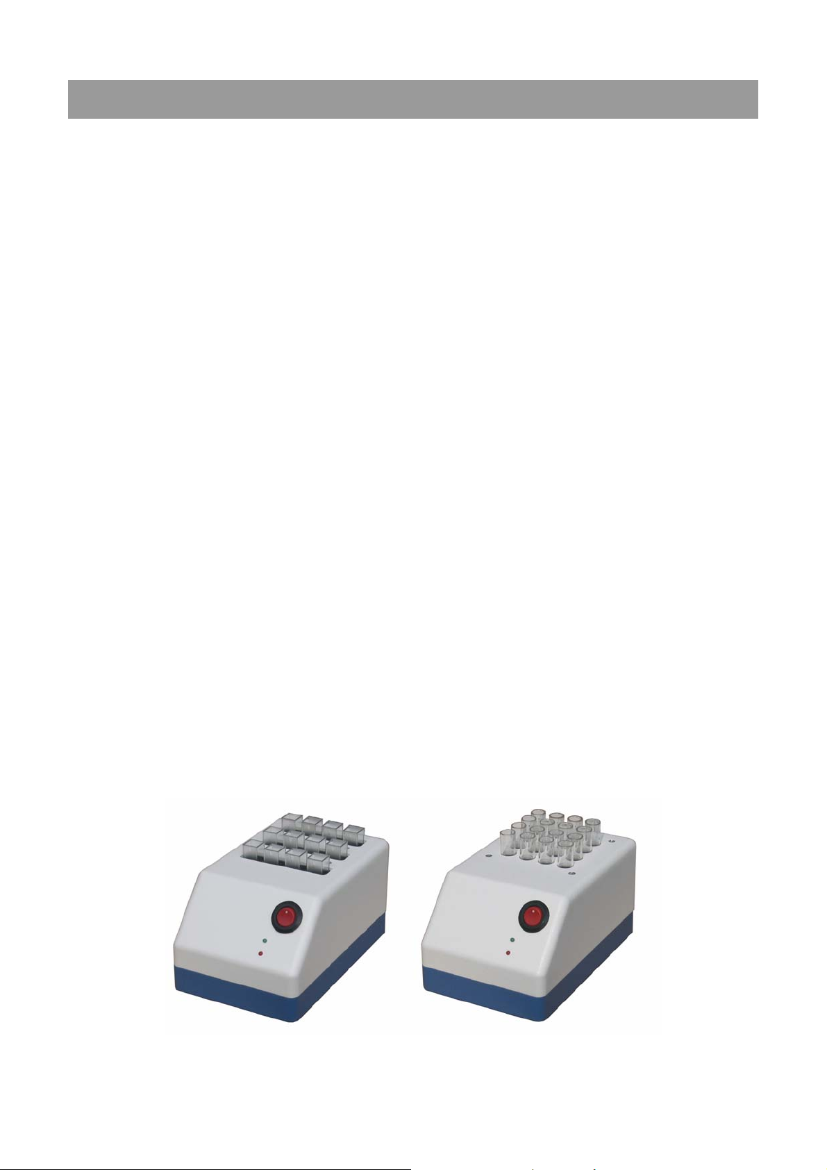
5010e_513.doc / 22.01.10
11 ACCESSORIES AND SPARE PARTS
Kindly contact directly the responsible dealer.
REF Description
5010-065 Aspiration tubing 185 mm, 2 pcs
1706853001 Axis printer paper
1706870001 Bubble detector with plug
0573655001 Cuvettes of optical glass, 4 pcs
501-002 Data cable serial interface
805-410 Disposable cuvettes, 1000 pcs
1704818001 Dust cover
1704796001 Flow through cuvette adaptor
5010-018 Fuses for line power, 10 pcs
0554871001 Halogen lamp 12V/20W
5010-024 Biogent-A, 1000 ml
0369624001 Interference filter 436nm
5010-670 Interference filter 670nm
(other wavelengths on request)
500-002 Incubator T12
500-001 Incubator T16
1707175001 Joint inlet tube cuvette
0552402001 Mains cable
5010-005 Operator’s manual
5010-066 Outlet tube cuvette, 5 pcs
1268457001 Printer paper, 5 rolls
1010735001 Printer ribbon, 1 pc
0745235001 Printer ribbon, 5 pcs
5010-050 Pump tube with joints
090-064 Secondary calibration standards, four-piece, certified
1704800001 Standard cuvette adaptor
090-063 Thermistor
1707574001 Top cover small for printer
1704834001 Waste tubing, 2 pcs
Incubator T12 Incubator T16
ROBERT RIELE GmbH & Co KG Page 72 11 -
ACCESSORIES AND SPARE PARTS

5010e_513.doc / 22.01.10
12 METHOD LIST
1 - 15..........15 basic methods (chapter 12.1 - BASIC METHOD)
16 - 19........free (reserved for further 4 automatic calculation methods)
20 - 250......up to 231 user specific methods (chapter 12.2 - LIST OF USER SPECIFIC METHODS as copy
master / to be filled out by the user)
12.1 BASIC METHODS
ROBERT RIELE GmbH & Co KG Page 73 12 -
METHOD LIST

5010e_513.doc / 22.01.10
12.2 LIST OF USER SPECIFIC METHODS
ROBERT RIELE GmbH & Co KG Page 74 12 - METHOD LIST
 Loading...