


LASER MIRROR SCANNER
LMS-Q280i
TECHNICAL DOCUMENTATION AND US E R’S INSTRUCTIONS
Version 07/2004 CE
Rev. 25-03-2004 (V5.63)
Rev. 01-07-2004 (V5.64)
(c) 2004 RIEGL Austria
All rights reserved.
This manual has been compiled with care. However, should you discover any
error, we would be grateful if you would let us know.
RIEGL Laser Measurement Systems GmbH
A-3580 Horn, Riedenburgstrasse 48, AUSTRIA
Tel.: +43-2982-4211, Fax.: +43-2982-4210
e-mail: office@riegl.co.at
www.riegl.com

I m p o r t a n t N o t e:
The LMS-Q280i makes use of a high power laser source and an extremely high
sensitive optical receiver. As a result of this powerful signal detection
electronics, the LMS-Q280i works with non-cooperative targets (natural
reflecting targets like trees, stones etc.) as well as with cooperative targets
(reflecting targets). The following reflecting target materials can be used:
o Reflecting paint
o Reflecting foil
Due to the high power level of the laser transmitter, high quality glass
retro-reflectors must not be used as a target !!! Using such retroreflectors can permanently damage the instrument.

C O N T E N S
1 GENERAL ................................................................................................ ... 1
1.1 System Configuration ................................................................ .............. 1
1.1.1 Rangefinder System................................................................ ............ 1
1.1.2 Scanner Mechanism................................................................ ............ 2
1.1.3 True Color Channel (optional)................................ ............................. 3
1.1.4 Interfaces................................................................ ............................. 4
2 DESIGN OF LASER SCANNER LMS-Q280I................................ .............. 5
2.1 Mechanical Design................................................................ ................... 5
2.2 Mechanical Drawings ................................................................ .............. 6
3 SAFETY INSTRUCTIONS................................................................ ........... 9
3.1 General Safety................................................................ .......................... 9
3.2 Electromagnetic Compatibility ............................................................. 11
3.3 Laser Safety ............................................................................................ 14
4 OPERATING INSTRUCTIONS .................................................................. 15
4.1 Preparing the Power Supply ................................................................. 15
4.1.1 Fuses ................................................................................................. 16
4.2 Connectors and Pin Assignments ........................................................ 17
4.2.1 Plug for Power Supply ....................................................................... 18
4.2.2 Plug for Serial Interface (RS232) ....................................................... 19
4.2.3 Plug for Parallel Interface .................................................................. 20
4.2.4 Plug for Ethernet Interface ................................................................. 21
4.3 Cables ..................................................................................................... 22
4.3.1 Power Supply Cable .......................................................................... 22
4.3.2 Parallel Data Cable ............................................................................ 23
4.3.3 Serial Data Cable .............................................................................. 24
4.3.4 LAN-TCP/IP Data Cable .................................................................... 25
4.4 Mounting the LMS-Q280i ....................................................................... 26
4.5 Instrument Cooling ................................................................................ 27
4.6 General System Set Up and Cabling .................................................... 27
4.7 Laser Setup and Test Procedure .......................................................... 29
5 SPECIFICATIONS ..................................................................................... 30
5.1 Technical data ........................................................................................ 30
5.2 Definition of axes ................................................................................... 32
5.3 LMS-Q280i Timing Characteristic ......................................................... 34
5.4 External Synchronization and Internal Reference Timer .................... 35
6 DATA COMMUNICATION AND I NTERFACES ........................................ 36
6.1 Programmin g Mode / M easur ement Mo de fo r Seria l Interf ace ................. 36
6.2 Data Format for Serial Interface ............................................................ 37
6.2.1 Data Format for Serial Interface in Programming Mode .................... 37
6.2.2 Data Format for Serial Interface in Measurement Mode .................... 38
6.3 Parameters and Controlling Commands ............................................. 41
6.3.1 Parameter Data Types in Programming Mode .................................. 41
6.3.2 Several Basic Commands ................................................................. 42

6.3.3 Basic Measurement Par am eter s ....................................................... 46
6.3.4 Adjusting Parameters for Serial Interface .......................................... 48
6.3.5 Definition of Scan Patter n .................................................................. 50
6.3.6 Several Additional Commands .......................................................... 54
6.3.7 Control Commands in Measurement Mode ....................................... 55
6.3.8 Additional Low Level Commands ...................................................... 56
6.4 ECP Data Output .................................................................................... 59
6.4.1 Reading Data via ECP ....................................................................... 59
6.4.2 Configuring the ECP Data Output ...................................................... 70
6.5 LAN interface .......................................................................................... 72
6.5.1 Overview ............................................................................................ 72
6.5.2 Activation ........................................................................................... 72
6.5.3 Configuring the LAN Interface ........................................................... 73
6.6 Errors and Error Handling ..................................................................... 75
6.7 Status and Error Messages ................................................................... 77

Page 1 of 79
Technical Documentation and
User Instructions
Laser Mirror Scanner LMS-Q280i
1 General
The Laser Mirror Scanner LMS-Q280i is a 2D laser scanner based upon
accurately measuring the distance by means of electro-optical pulsed time-offlight range measurement and upon f ast scanning the laser beam by m eans of
an opto-mechanical scan mechanism. The high range performance, the fast line
scanning, and the overall system design makes the LMS-Q280i well suited for
airborne laser scanning applications.
1.1 System Configuration
The laser scanner LMS-Q280i consists mainly of two subsystems, an accurate
laser rangefinder electronics and a line scanning mechanism, installed in a
rugged housing.
1.1.1 Rangefinder System
The rangefinder system is based upon the principle of time-of-flight
measurement of short infrared laser pulses.
A laser source emits infrared light pulses, which are collimated by a transmitter
lens system. Via the receiver lens, part of the echo signal reflected by the target
hits a photodiode which generates an electrical receiver signal. The time
interval between transmitted and received pulses is counted by means of a
quartz-stabilized clock frequency. The measured time value is passed to the
internal microcomputer which processes the measured data and prepares it for
data output.
Fig. 1 Measurement principle of the pulsed range finder

Page 2 of 79
Technical Documentation and
User Instructions
Laser Mirror Scanner LMS-Q280i
S
c
a
n
n
e
d
l
a
s
e
r
b
e
a
m
Rotating
polygonal
mirror
T
r
a
n
s
mi
t
t
e
r
R
e
c
e
i
v
e
r
1.1.2 Scanner Mechanism
The scanner mechanism deflects the laser beam for range measurement into a
precisely defined direction. Each scan line is composed of a number of pixels
(single laser measurements).
The angular deflection of the laser beam is realized by a rotating polygon mirror
wheel. The polygon-mirror is composed of flat reflective surfaces arranged
around the wheel perimeter. The wheel rotates continuously at a fixed speed to
provide repetitive unidirectional scans.
Fig. 2 Principle of beam deflection by a rotating mirror

Page 3 of 79
Technical Documentation and
User Instructions
Laser Mirror Scanner LMS-Q280i
Due to the finite aperture dimensions, only a fractional part of the polygon mirror
surfaces (excluding the edge areas) can be used for scanning (please refer to
chapter 5.3, LMS-Q280i Timing characteristic).
1.1.3 True Color Channel (optional)
Beside the laser transmitter and the laser receiver, the LMS-Q280i has
optionally an integrated true color channel which provides the color of the
target´s surface as an additional information to each laser measurement. Color
data are included in the binary data stream of the LMS-Q280i allowing
straightforward texturing of scanned surface model.

Page 4 of 79
Technical Documentation and
User Instructions
Laser Mirror Scanner LMS-Q280i
1.1.4 Interfaces
1.1.4.1 Electrical Interfaces
The laser sca nner LMS-Q280i requires a singl e power supply with no minall y 24V DC .
Supply voltage 24V DC
Permitted supply voltage range 18V DC to 32V DC
Current consumption
(scanning operation)
1.1.4.2 Data Interfaces
LAN Interface Ethernet Network interface, using the
RS232 serial interfac e Bi-directional interface for scanner
Parallel interface ECP compatible, Uni-directional interface,
typically 3A at 24V DC
TCP/IP protocol
configuration
provides the scan data
The pin assignment of the interface connectors can be found in chapter 4.2,
Connectors and Pin Assignments.

Page 5 of 79
Technical Documentation and
User Instructions
Laser Mirror Scanner LMS-Q280i
2 Design of Laser Scanner LMS-Q280i
2.1 Mechanical Design
The housing of the LMS-Q280i laser scanner is designed to meet the
requirements for an installation on board of an airplane or helicopter. The slim
design and the scan direction perpendicular to the longitudinal axis of the laser
scanner allows straightforward integration also under narrow space conditions.
The housing consists of a very stable base plate, which carries 6 pcs. M6
mounting threads and the beam output aperture window.
The top plate provides 6 pcs. M6 mounting threads for the installation of an
inertial measurement unit or other additional equipment. This mounting threads
are firmly connected to the internal frame structure. Additionally, the top plate is
equipped with a heat-sink profile.
For adequate heat dissipation, the rear plate
profile. On this side of the laser scanner, there are the connectors for power
supply and data interface as well as the fuse holders located.
For additional information about heat dissipation, please refer to chapter
Instrument Cooling
The front plate carries a desiccant cartridge and valve for nitrogen purging of
the instrument.
The side plates are made of aluminum pro file s hel ls .
All outer parts are colorless or black anodized.
The figures on the next pages show the mechanical dimensions of the LMS-
is equipped with a heat-sink
4.5,
Q280i laser scanner.

Technical Documentation and
User Instructions
Laser Mirror Scanner LMS-Q280i
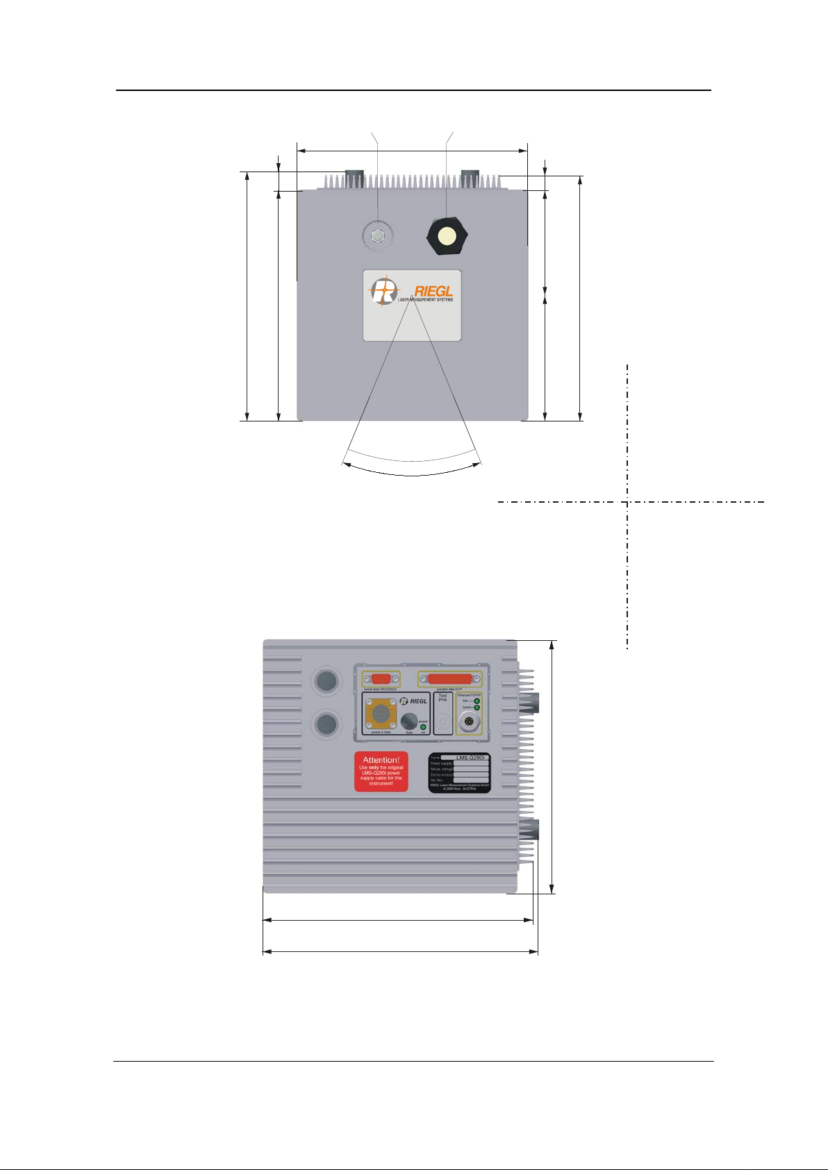
2.2 Mec ha nical Drawings
24.5
262
505
75
156
95.5
560
132
200
135
6xM6
mounting
threads
depth 10 mm
scan
window
center of laser beam output
Page 6 of 79
Fig. 3 Bottom view of LMS-Q280i (base plate side)

Technical Documentation and
User Instructions
Laser Mirror Scanner LMS-Q280i
78
186
408
100
6xM6
mounting
threads
depth 10 mm
heat sink
profile
Page 7 of 79
Fig. 4 Top view of LMS-Q280i (top plate side)
Page 8 of 79
Technical Documentation and
User Instructions
Laser Mirror Scanner LMS-Q280i
www.riegl.com
108.8
213
200
217
-22.5°
+22.5°
scanned laser beam
(up to ±30°)
desiccant
cartridge
fitting for
purging
200
17
91.2
13
213
200
217
Fig. 5 Front view of LMS-Q280i (front plate side)
Fig. 6 Rear view of LMS-Q280i (rear plate side)

Page 9 of 79
Technical Documentation and
User Instructions
Laser Mirror Scanner LMS-Q280i
exceeds the requirements of the following European
Safety requirements for electrical
Temperature:
See chapter 5 Specifications for temperature limits for storage
Storage and operation at temperatures outside the specified
surement results or
technique to determine the distance to the object. For this
purpose it comprises sensitive optical, electrical and
appropriate handling:
Unnecessary exposure of the internal optical and electronic
should be
The unit is specified for an altitude up to 2000m (operation or
Relative
The unit is specif ied for a relative humidity of 80% at or below
Enclosure:
is water resistant on the outside
dripping water or
The optical glass panes should be treated with the care
customarily due to optical instruments and, only when
absolutely necessary, should they be gently cleaned using a
Never apply mechanical force or shock to the glass panes
should be
protected from being shaken or knocked.
3 Safety Instructions
3.1 General Safety
GENERAL SAFETY EN 61010-1
LMS-Q280i meets or
Standard: EN 61010-1 (April 1993)
equipment for measurement, control, and laboratory use Part 1: General
Requirements
Note the following explanations and important instructions:
and operation.
Sunlight: The LMS-Q280i makes use of the optical time-of-flight
Altitude:
Humidity:
temperature ranges may cause wrong mea
even damage of the instrument.
mechanical components. Thus the LMS-Q280i requires
parts to direct sunlight via the front window
avoided.
storage).
+31°C; linearly decreasing to 50% at +40°C.
The instrument LMS-Q280i
but must not however be subjected to rain or
submerged under water.
suitable lens cleaning fluid (e.g. pure ethylene alcohol).
or to the housing itself!
As with other optical instruments, the LMS-Q280i

Page 10 of 79
Technical Documentation and
User Instructions
Laser Mirror Scanner LMS-Q280i
Power supply:
Before operating the LMS-Q280i make sure that its case is
The power supply cable is to be connected with a suitable
power supply with a maximum voltage of 32 V DC
be connected to 110 or 230
unacceptable due to the danger
presented by the high voltages, and must therefore be
The negative pole of the external line voltage is directly
connected to the instrument’s housing. This should be
ANY USE OF THE LMS-Q280i IN CONTRADICTION TO THE
THEREFORE, STRICTLY FORBIDDE N!
properly grounded.
DC-
(nominal 24 V DC).
The instrument must never
VAC!
Opening the instrument is
avoided at all costs.
remembered when connecting it to other instruments.
INSTRUCTIONS AS GIVEN IN T HE MANUAL CAN BE DANGEROUS AND IS,

Page 11 of 79
Technical Documentation and
User Instructions
Laser Mirror Scanner LMS-Q280i
meets or exceeds the requirements of the following
WARNING:
, which is affixed on the front side of the housing
of the instrument, meets the requirements of the commission’s guideline
be used in residential, commercial
3.2 Electromagnetic Compatibility
ELECTROMAGNETIC COMPATIBILITY EN 61326
1
Laser scanner LMS-Q280i
European Standards:
EN 61326-1 (1997) Electrical equipment for measurement, control and
laboratory use; EMC requirements; P a rt 1: General requirements
(IEC 61326-1:1997)
EN 61326/A1 (1998) Electrical equipment for measurement, control and
laboratory use; EMC requirements (IEC 61326:1997/A1:1998)
The LMS-Q280i is a class A equipment intended for industrial
environment. Therefore, it must not
and light industry environment.
The labeli ng of the LMS-Q280i
89/336/EEC:
1)
The tests have been run using default scanner parameter settings. The tests
have been performed using original RIEGL data and power supply cables,
powered with 24 V DC provided by an PbGel-Powerpack.
To maintain emission requirements when connecting to the I/O interface of the
LMS-Q280i use only a high-quality shielded data interface cable. The cable
shield must have low impedance connections to both connector housings.
Any changes or modifications to the standard equipment not expressly
approved by RIEGL as well as any non-observance if the directions for
installation may cause harmful interference and void the authorization to
operate this equipment.
The following table lists the applied standards and the performance criteria (see
also definition below) for the evaluation of the immunity test results:
CISPR 16-1 Edition 2.1: 2002
Specification for radio disturbance and immunity measuring apparatus and
methods; Part 1: Radio disturbance and immunity measuring apparatus
CISPR 16-2 Edition 1.2: 2002
Specification for radio disturbance and immunity measuring apparatus and
methods; Part 2: Methods of measurement of disturbances and immunity

Page 12 of 79
Technical Documentation and
User Instructions
Laser Mirror Scanner LMS-Q280i
EN 61000-4-2 + A1 + A2 : 2002
Electromagnetic compatibility (EMC); Part 4-2: Testi ng and me asurement
techniques - Electrostatic discharge immunity test (IEC 61000-4-2:1995 +
A1:1998 + A2:2001)
Performance Criter ion B
EN 61000-4-3 + A1 + A2: 2002
Electromagnetic compatibility (EMC); Part 4-3: Testi ng and me asurement
techniques - Radiated, radio frequency, electromagnetic field immunity test
(IEC 61000-4-3:1995 + A1:1998 + A2:2000)
Performance Criter ion A
EN 61000-4-4 + A1 + A2: 2002
Electromagnetic compatibility (EMC); Part 4-4: Testi ng and me asurement
techniques - Electrical fast transient/burst immunity test (IEC 61000-44:1995 + A1:2000 + A2:2001)
Performance Criter ion B
EN 61000-4-5 + A1: 2002
Electromagnetic compatibility (EMC); Part 4-5: Testi ng and me asurement
techniques - Surge immunity test (IEC 61000-4-5:1995 + A1:2001)
Performance Criter ion C
EN 61000-4-6 + A1: 2002
Electromagnetic compatibility (EMC); Part 4-6: Testi ng and me asurement
techniques - Immunity to conducted disturbances, induced by radio
frequency fields (IEC 61000-4-6:1996 + A1:2000)
Performance Criter ion A
EN 61000-4-8 + A1: 2002
Electromagnetic Compatibility (EMC); Part 4-8: Testing and Measurement
Techniques - Power Frequency Magnetic Field Immunity Test (IEC 610004-8:1993 + A1: 2000)
Performance Criter ion A
Definition of the performance criteria and acceptable degradations:
Performance Criterion A: during testing, normal performance within defined
limits
• additional distance depending range error up to ±10 cm;
• additional statistical range error up to ±25 cm;
• loss of ran ge
• additional angle error up to ±1 °;
Performance Criterion B: during testing, temporary degradation or loss of
function or performance which is self-recovering
• loss or heavy degradation of functionalities during testing with selfrecovering after finishing the test;

Page 13 of 79
Technical Documentation and
User Instructions
Laser Mirror Scanner LMS-Q280i
Performance Criterion C: during testing, temporary degradation or loss of
function or performance which requires operator intervention or system
reset occurs
• loss or heavy degradation of functionalities during testing with selfrecovering after finishing the test; a system reset may occur;
• loss or heavy degradation of functionalities which require simple user
intervention, e.g. replacement of a fuse, switching the device Off and On,
restoration of settings;

Page 14 of 79
Technical Documentation and
User Instructions
Laser Mirror Scanner LMS-Q280i
the instrument may
! Do not operate evidently damaged
d incompetently, the
manufacturers absolve themselves from granting any guarantee or
3.3 Laser Safety
The laser scanner instrument LMS-Q280i is classified as Class 1 laser product
in compliance with the International Eye safety regulation IEC60825-
1:1993+A1:1997+A2:2001 and the European Eye safety regulation EN608251:1994+A1:2002+A2:2001 Safety of Laser Products, Equipment Classification,
Requirements and User´s Guide.
Class 1: Lasers which are safe under reasonably foreseeable conditions of
operation, including the use of optical instruments for intrabeam viewing
(IEC60825-1:2001, Sub-clause 8.2).
The labeling of the LMS-Q280i meets the requirements of the above standard
(IEC60825-1:2001, sub-clause 5.1 and 5.2). It is affixed two times near the front
pane on the LMS-Q280i.
CAUTION! The invisible laser radiation inside
exceed the accessible emission limits of laser class 1, thus never
open the instrument’s housing
instruments! If the instrument is handle
insurance whatsoever.
Aligning the infrared laser instrument with the lenses of CCD-cameras or
infrared night vision devices can result in damage to them and is therefore not
permitted.
Note: The laser beam exits the instrument via the front window as
indicated in the mechanical drawings.
IMPORTANT NOTE : This classification is based on the condition that the laser
beam is continuously scanned. The LMS-Q280i emits laser radiation only, when
in scanning operation. In case of any fault of the driving mechanism, the laser is
switched off immediately.

Page 15 of 79
Technical Documentation and
User Instructions
Laser Mirror Scanner LMS-Q280i
RS232: RxD & TxD
laser safety lock
RS232: GND
RS422: (optional)R & T
GND output
+UB input
GND input
laser mirror scanner
housing = ground = GND input =
= GND RS232 (RS422 optional) =
= GND ECP port = GND output
(connections inside the instrume nt)
LMS-Q280
RS422: (optional)GND
ECP port data lines
ECP port GND
4 Operating Instructions
4.1 Pre pa ring the Power Supply
• All ground terminals of data interfaces, control lines and power supply and
the housing are internally connected (common ground). Details are shown by
the following scheme:
• The connections between the ground terminals and the housing, which are
within the instrument, are not suitable to drain off potential differences.
Therefore, further ground connections have to be provided during installation.
• The DC-power supply has to fulfill the requirements for ‘Limited Circuit’
according to EN 61010-1 and the requirements for ‘SELV’ circuits according
to EN 60950.
• The power supply cable is to be connected to a suitable DC power supply
with a voltage specified in chapter 5 Specifications. The negative pole of the
supply voltage has to be grounded.
• The LMS-Q280i is protected by 3 fuses (located on the rear plate of the
instrument), one for the range finder part electronics, one for the scanning
mechanism and one for the laser transmitter (for fuse types and ratings see
chapter 4.1.1). The current drain capacity of the power supply must be at
least three times the sum of the rated currents of the three fuses, so the
fuses can be activated reliably if necessary (for example, in the case of false
polarity).
• When using a long power supply cable, the drop of voltage should be
considered when adjusting the supply voltage. The negative pole of the
supply voltage should be connected to ground near the instrument.
• The internal resistance of the power supply must be low enough for the
supply voltage not to fall short below the minimum voltage of the instrument.
• The control inputs, analog and digital outputs, and the serial interface of the
laser mirror scanner may be connected only to equipment fulfilling the
requirements for ‘SELV’ circuits according to EN 60950.
•
For e lectromagnetic compatibility, use only original RIEGL power supply
cables and low-noise power supply units, which meet the relevant CE
requirements.

Page 16 of 79
Technical Documentation and
User Instructions
Laser Mirror Scanner LMS-Q280i
fuse holder for scanning mechanism
fuse holder for laser module
fuse holder for rangefinder electronics
4.1.1 Fuses
The laser scanner LMS-Q280i is equipped with 3 glass tube fuses. The fuse
holders are located at the rear side of the instrument.
2.0 A quick-acting
(according to IEC60127 and EN60127)
1.25 A quick-acting
(according to IEC60127 and EN60127)
1.0 A quick-acting
(according to IEC60127 and EN60127)
Fig. 7 Fuse Holders LMS-Q280i
The fuse holders can be opened and closed by means of a coin used like a
screw driver.
Note: Replace a blown fuse only with specified type and rated fuse!

Page 17 of 79
Technical Documentation and
User Instructions
Laser Mirror Scanner LMS-Q280i
serial interface
parallel ECP interface
power & control lines
test plug
LAN interface
4.2 Connectors and Pin Assignments
The connectors for power supply and data interface are located at the rear side
of the LMS-Q280i.
(for service
Fig. 8 Connectors for power supply and data interfaces
purposes only)

Page 18 of 79
Technical Documentation and
User Instructions
Laser Mirror Scanner LMS-Q280i
4.2.1 Plug for Power Supply
Type of connector : Souriau 851 02E 12-10 P50, male
Pin Assignment Color Note
A Laser safety lock brown
B *) not used for LMS-Q280i
C GNDin yellow
green
D *) not used for LMS-Q280i
E Trigger yellow Input for external SYNC
F Marker green TTL output factory
G +UB 18-32 VDC black 2 Power Supply
H GNDout white
J GNDin black 3 Power Supply Ground
K +UB 18-32 VDC black 1
*) Any use of these pins for whatever connections can damage the data output
and is, therefore, strictly prohibited!
Power Supply Ground
signal
internal usage
Power Supply

Page 19 of 79
Technical Documentation and
User Instructions
Laser Mirror Scanner LMS-Q280i
4.2.2 Plug for Serial Interface (RS232)
Type of connector : Sub-D, 9-pin, male
Pin Assignment Color Note
1 must not be connected *)
2 RxD RS232 data input
3 TxD RS232 data output
4 must not be connected *)
5 GND Signal GND
6 must not be connected *)
7 must not be connected *)
8 must not be connected *)
9 must not be connected *)
*) Any use of these pins for whatever connections can damage the data output
and is, therefore, strictly prohibited!
The serial data interface is used for configuration of the scanner.

Page 20 of 79
Technical Documentation and
User Instructions
Laser Mirror Scanner LMS-Q280i
1
2
RD
Data 1 (LSB)
Data 1
7
RD
Data 6
Data 6
12
17
22 Signal GND
4.2.3 Plug for Parallel Interface
Type of plug: Sub-D, 25-pin, male
Pin Source Name Centronics Name
3 RD Dat a 2 Data 2
4 RD Dat a 3 Data 3
5 RD Dat a 4 Data 4
6 RD Dat a 5 Data 5
8 RD Dat a 7 Data 7
9 RD Data 8 (MSB) Data 8
10 RD PeriphClk nAck
11
13
14 PC HostAck nAutoFd
15
16 PC Direction nInit
18 Signal GND
19 Signal GND
20 Signal GND
21 Signal GND
23 Signal GND
24 Signal GND
25 Signal GND
PC...Personal Computer
RD...Riegl Device
Levels are TTL-levels
For detailed information about the parallel data interface, please refer to chapter
6.4, ECP Data output.

Page 21 of 79
Technical Documentation and
User Instructions
Laser Mirror Scanner LMS-Q280i
4.2.4 Plug for Ethernet Interface
Manufacturer: Lumberg Inc.
Type: Micro (M12) Female/S3426 Receptable
Number of Pins: 8
For detailed information about the Ethernet data interface, please refer to
chapter 6.5 LAN interface .
Page 22 of 79
Technical Documentation and
User Instructions
Laser Mirror Scanner LMS-Q280i
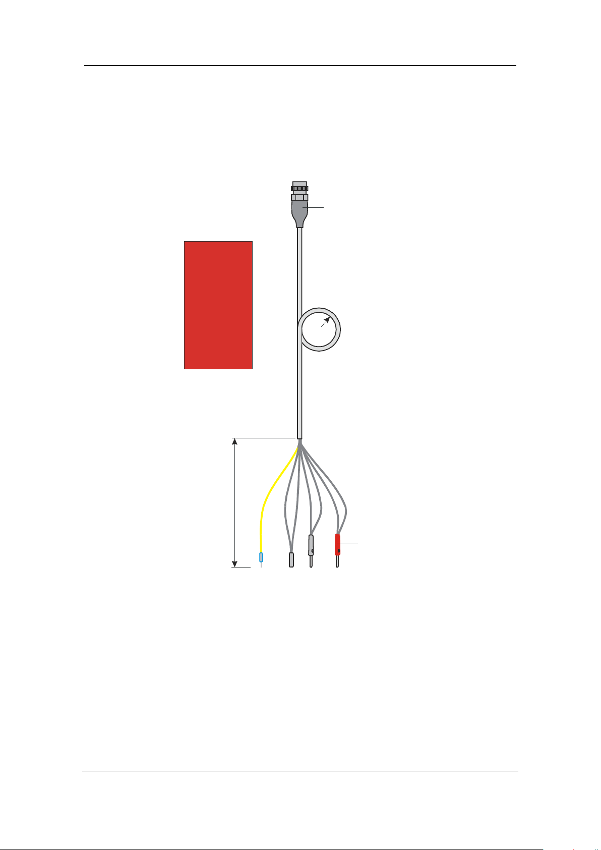
Attention!
Use this power supply
cable for scanner
type LMS-Q280i
only
A
t
te
n
tio
n
!
U
s
e
t
h
is
p
o
w
e
r
s
u
p
p
ly
c
a
b
le
f
o
r
s
c
a
n
n
e
r
ty
p
e
L
M
S
-
Q
2
8
0
i
o
n
l
y
10-pole plug /female,
series 851
>200mm
shielded cable
20 cm
banana plugs
T
r
ig
g
e
r
/ y
e
llo
w
L
a
s
e
r
s
a
fe
ty
lo
c
k
&
G
N
D
o
u
t / b
r
o
w
n
&
w
h
ite
G
N
D
in
p
u
t /
b
la
c
k
3
&
y
e
llo
w
/g
r
e
e
n
+
U
b
/ b
la
c
k
1
&
2
4.3 Cables
The laser scanner LMS-Q280i is shipped with three cables.
4.3.1 Power Supply Cable
The length of the cable is approx. 6m.
Fig. 9 Power supply cable
Page 23 of 79
Technical Documentation and
User Instructions
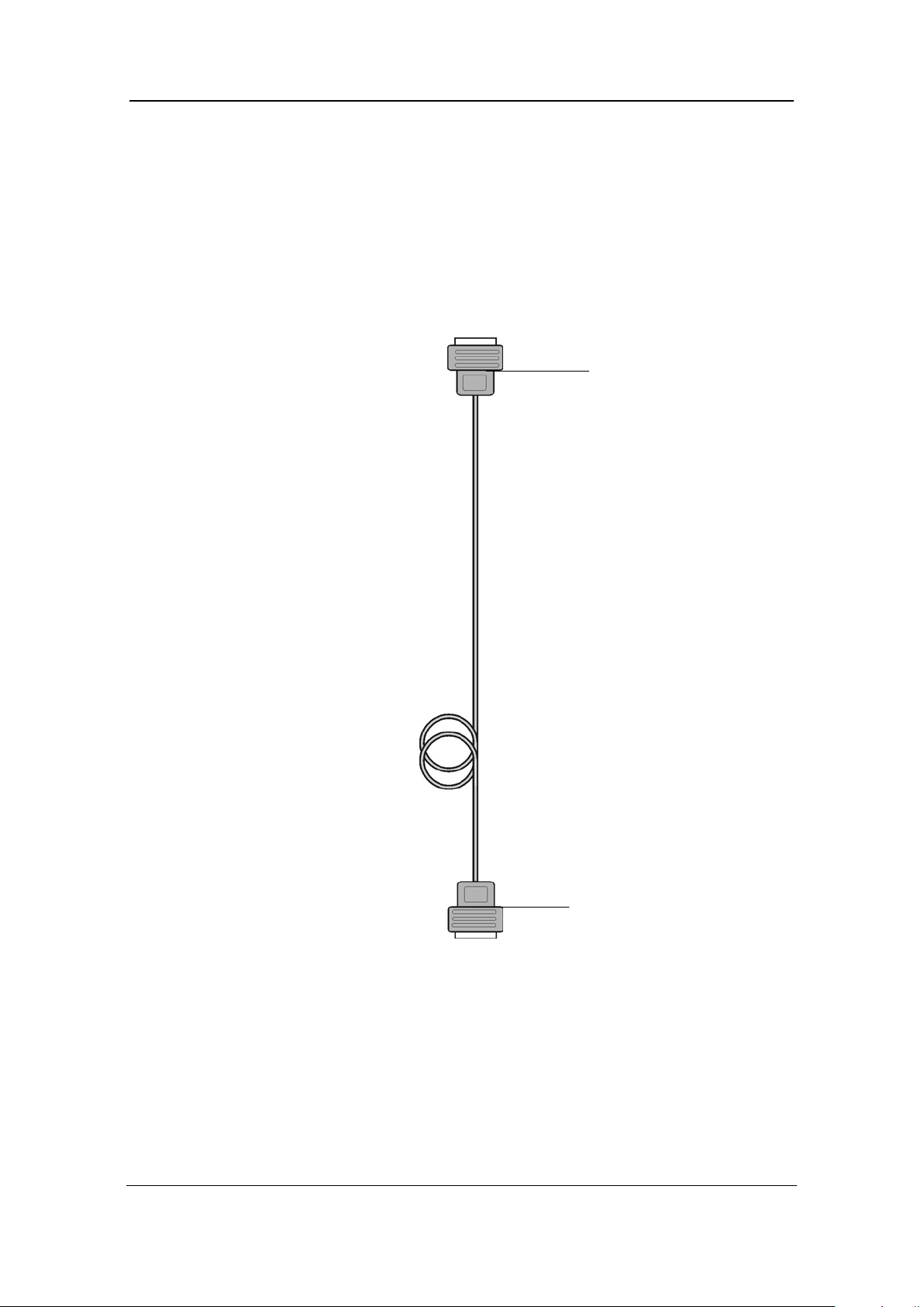
Laser Mirror Scanner LMS-Q280i
25-pole Sub-D
25-pole Sub-D
4.3.2 Parallel Data Cable
The parallel data cable uses a standard PC-Printer cable pinning, but needs
improved noise immunity to ensure highest possible data transfer rates. The
cable has to meet the requirements of IEEE Std. 1284-1994. The end of the
parallel cable is equipped with 25-pole Sub-D connectors enabling to connect
the LMS-Q280i directly to the LPT printer port of a personal computer. The
length of the parallel cable is approx. 6 m .
connector, female
Fig. 10 Parallel data cable
connector, male

Technical Documentation and
User Instructions
Laser Mirror Scanner LMS-Q280i
4.3.3 Serial Data Cable
9-pole Sub-D
9-pole Sub-D
Cable configuration:
Page 24 of 79
The cable length is approx. 3m.
connector, female
Fig. 11 Serial data cable
connector, female
Page 25 of 79
Technical Documentation and
User Instructions
Laser Mirror Scanner LMS-Q280i
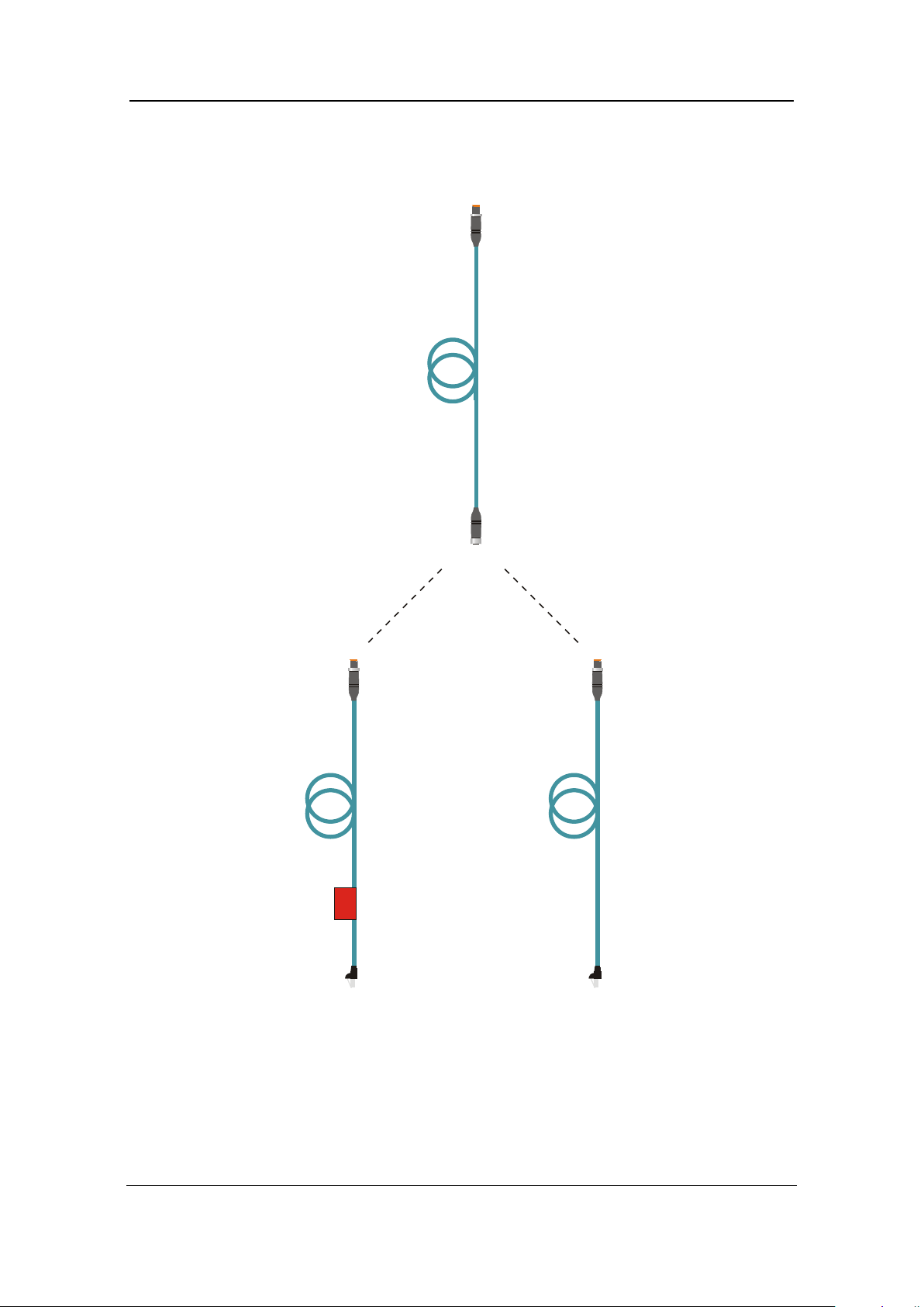
typically to Ethernet Hub
typically to PC/Laptop
4.3.4 LAN-TCP/IP Data Cable
Using the included Ethernet Interface cables the LMS-Q280i can be connected
to an Ethernet hub or to a PC/Laptop Ethernet connector.
TCP/IP cable
M12-M12, length 3 m
Fig. 12 Ethernet interface cable
cable for direct connection
between LMS-Zxx and PC
Use this cross over
Attention!
M12-RJ45, cross over, length 0.3 m
TCP/IP cable
TCP/IP cable
M12-RJ45, length 0.3 m

Page 26 of 79
Technical Documentation and
User Instructions
Laser Mirror Scanner LMS-Q280i
4.4 Mounting the LMS-Q280i
The base plate of the LMS-Q280i provides 6 pcs. steel inserts with M6 threads,
depth 10mm. This threads are intended to be used for mounting the laser
scanner to a shock proof support plate. For installation of an inertial
measurement unit, the LMS-Q280i provides additionally 6 pcs. steel inserts with
M6 threads in the heat sink profile of the top plate, which are firmly connected to
the internal frame structure. The position of these mounting threads can be
found in the drawing below.
Fig. 13 Position of mounting threads

Page 27 of 79
Technical Documentation and
User Instructions
Laser Mirror Scanner LMS-Q280i
4.5 Inst rument Cooling
To enable appropriate heat dissipation by means of natural air convection, the
heat sink profiles must not be covered by objects which are located very closed
to the laser scanner. Operation at higher ambient temperature and/or reduced
air convection (low atmospheric pressure) could require additional forced
cooling (external fan). The housing surface temperature should not exceed
+40°C.
4.6 Gener a l System Set Up and Cabling
• Provide a suitable power supply for the laser scanner (please refer to
chapter 4.1, Preparing the Power Supply).
• Mount the laser scanner LMS-Q280i by means of the mounting threads.
• Connect the LAN-TCP/IP interface or alternatively the parallel and the
serial interface of the instrument to a personal computer or equivalent
data acquisition unit using the LAN cable or the parallel and serial
connection cables.
• Connect the instrument to the power supply using the power supply
cable.
After switching-on the power supply the scanner starts with
• the “Laser setup and test procedure” (see chapter 4.7 for details),
and then
starts scanning automatically .

Page 28 of 79
Technical Documentation and
User Instructions
Laser Mirror Scanner LMS-Q280i
Fig. 14 Cabling of laser scanner LMS-Q280i

Page 29 of 79
Technical Documentation and
User Instructions
Laser Mirror Scanner LMS-Q280i
4.7 Laser Setup and Test Procedure
At power up a laser setup and test procedure, typically lasting 20 seconds
(the effective time depends on instrument’s and ambient temperature) is
executed. A beep sequence indicates that the setup procedure is in progress.
If the laser setup and test procedure is passed, the laser is ready for
measurement, otherwise an error message is sent.

Technical Documentation and
User Instructions
Laser Mirror Scanner LMS-Q280i
5 Specifications
1)
1500 m
Measurement accuracy
2)
(1σ standard deviation)
First target, last target (up to 4 echoes)
or alternating
Laser pulse repetition rate
PRR
24.000 Hz
:
4)
5.1 Technical data
Technical Data of the Scanning Mechanism
Scanning mechanism: rotating polygon mirror
Number of mirror facets: 4
Scan angle range: 45° (60° at 90% meas. range)
Angular movement: linear
Page 30 of 79
Scan speed : 5 lines/s up to max.80 lines/s
Minimum angle step width : 0.02°
Angle readout resolution: 0.0025°
1) Scanning rates selectable via LAN-TCP/IP or serial interface, max. 30 scans/sec. for 60°
scanning range
Technical Data of the Laser Range Measurement
Measurement principle: Single-shot time-of-flight measurement
Measurement range
for natural targets, ρ ≥ 20%
for natural targets, ρ ≥ 80%
1)
850 m
Maximum range : 2000 m
Minimum range: 30 m
typ.± 20 mm
Measurement resolution:
5 mm
Target detection modes :
3)
Laser wavelength:
Laser beam divergence
Eye safety class according
to IEC60825-1:2001 5)
1) The following conditions are assumed:
• target is larger than the foot print of laser beam
• normal incident angle of laser beam
• visibility 10 km
• average ambient brightness
2) Standard deviation, plus distance depen di ng err or ≤ ± 20ppm
3) Average measurement rate is 1/2 of PRR rate @ scan angle range 45°
4) 0.5 mrad corresponds to 5 cm beam width per 100m distance
5) The classification is based upon the assumption that the laser beam is continuously
scanned.
near infrared
0.5 mrad :

Technical Documentation and
User Instructions
Laser Mirror Scanner LMS-Q280i
560 x 200 x 208,5
(L x W x H)
Temperature range:
Storage:
-10°C up to +50°C
Ethernet, twisted pair LAN,10 /
- Laser safety lock line
- TTL output (optionall y)
Provides the color of target surface as an additional information to each
laser measurement.
co-aligned with transmitter and
receiver channel
blue: 380-470 nm
red: 590–710 nm
Physical and Electrical Data
Main dimensions :
Weight : 20 kg
Protection class: IP54
Page 31 of 79
Operation:
Power consumption: approx. 70 W
Voltage supply range: 18 – 32 V DC
Interfaces
Mechanical interface Steel thread inserts
100 MBit, industrial connector
Serial Interface for configuration,
Data interface
Power supply 10 pin MIL connector
Additional control lines
industrial Sub connector
Parallel ECP interface for data
output , industrial Sub-D
connector
- TTL input for synchronization
0°C up to +40°C
Orientation
Resolution 16 bit each color
Spectral range
Field of view 1.4 mrad
Optional True Color Channel
green: 510-590 nm

Page 32 of 79
Technical Documentation and
User Instructions
Laser Mirror Scanner LMS-Q280i
5.2 Definition of axes
The following drawing shows the definition of the coordinate system of the LMSQ280i.
X-axis
108.8 108.2
Y-axis
Z-axis
Z-axis
Y-axis
156
X-axis
Fig. 15 Definition of axes 1

Page 33 of 79
Technical Documentation and
User Instructions
Laser Mirror Scanner LMS-Q280i
point no. X Y Z
1 -108.2 -252 50
2 -108.2 -252 -50
3 -108.2 -30 50
4 -108.2 -30 -50
5 -108.2 78 50
6 -108.2 78 -50
Coordinates of mounting points for IMU
Z
-X
-Y
Y
X
-Z
ϕ(=0)
ϑ
www.riegl.com
108.8
Y-axis
X-axis
Z-axis
origin of scanner’s
local coordinate system
78
186
408
6xM6
mounting
threads
depth 10 mm
1 2
3 4
5
6
Z-axis
Y-axis
X-axis
100
Fig. 16 Definition of axes 2

Page 34 of 79
Technical Documentation and
User Instructions
Laser Mirror Scanner LMS-Q280i
1 second
L
in
e
S
c
a
n
A
n
g
le
5.3 LMS-Q280i Timing Characteristic
As mentioned in chapter 1.1.2, only a part of the mirror facets can be used for
data acquisition. At the edges of the facets the laser beam is split into two
beams and no measurement is possible. The utilization of 45° out of 90° results
in a duty factor of 50 percent. That is the reason for gap times between two
consecutive scan lines. Fig. 16 shows the timing situation for the LMS-Q280i.
t=1second / Scanning rate
112.5°
90°
s
e
ls
u
P
r
e
s
a
L
scan1
t
scan
Gap
t
gap
scan2 scan N
t
t
t
67.5°
Fig. 17 Timing diagram for the scan mechanism
t laser = 1 / PRR (Pulse repetition rate)
Magnified view
Line Scan angle x t laser [ms]
ts[ms]

Page 35 of 79
Technical Documentation and
User Instructions
Laser Mirror Scanner LMS-Q280i
5.4 External Synchronization and Internal Reference Timer
The LMS-Q280i provides an internal timer with a timing resolution of 10 µs. It is
a 3 byte wide timer and automatically started at power up. With 3 bytes it
overruns every 167.77216 seconds.
The timer value at the start of the scan data line (LineTimeStamp) is
provided for further data processing within the trailer data contained within each
scan line data (see chapter, 6.4.1.4 Structure of trailer). Additionally, a
LaserShotTimeStamp can be added to each measurement, if more detailed
timing information is needed (see chapters 6.4.2 (Fn command) , 6.4.1.3 and
6.4.1.4)
Additionally, the instrument provides an input f or an external SYNC pulse. The
external SYNC pulse synchronizes the internal timer to an external event (e.g.
1pps GPS pulse). The rising edge of the external pulse resets the internal timer
and the number of external SYNC pulses are counted. The counter value is
supplied optionally in the trailer data ( SyncCounter, see chapter 6.4.1.4 )
Specifications of the external SYNC pulse:
Signal level : TTL, positive,
with respect to
GNDout
Pulse duration : min. 15µs
Trigger edge : rising edge
The input is protected against over voltage and negative voltage.

Page 36 of 79
Technical Documentation and
User Instructions
Laser Mirror Scanner LMS-Q280i
6 Data Communication and Interfaces
When using t he LMS -Q280i without Ethernet / TCPIP interface, 2 interfaces are
used:
• a serial RS232 (PC COM-Port) interface for configuration and control
• a parallel ECP (PC LPT-Port) interface for fast scan data outp ut
With the Ethernet / TCPIP interface, these 2 interfaces (2 cable connections)
can be replaced by one interf ace (one cable), using 2 ports: a da ta port (port
number 20001) and a configuration port (port number 20002).
All syntax rules and data format / structure descriptions of the followi ng chapters
are identically used for communication via the TCPIP interface ports, where the
rules relevant for the serial interface are used for the configuration port and the
data structures for ECP parallel interface are used for the data port.
With Ethernet / TCPIP interface some specific commands for TCPIP
configuration ( e.g. IP-address) have to be previously set using the serial RS232
interface.
6.1 Programming Mode / Measurement Mode for Serial Interface
The instrument provides a programming mode to set and display measurement
and control parameters. To enter the programming mode (leaving the
measuring mode) send a ^P (Ctrl P, ASCII 10hex) to the instrument, to leave
the programming mode (re-entering the measuring mode) send a Q<Cr> (like
quit). <Cr> means Carriage return (ASCII 0Dhex).
Measurements and scans are carried out in the measurement mode. After
power up the instrument starts with measurement m ode.
The communication parameters are pre-adjusted in factor y to
19200 baud
1 start bit
8 data bits
no parity
1 stop bit
For achieving electromagnetic compatibility, use original RIEGL data
cable for communications only!

Page 37 of 79
Technical Documentation and
User Instructions
Laser Mirror Scanner LMS-Q280i
6.2 Data Format for Serial Interface
6.2.1 Data Format for Serial Interface in Programming Mode
The programming mode uses ASCII character strings to set parameters or ask
for current parameter settings. After starting programming mode with command
^P, the instrument replies with the message
*<Cr>[<Lf>]
where <Cr> means a Carriage return (0Dhex) and [<Lf>] means an optional
Line Feed (0Ahex) (<Cr> or <Cr><Lf> sequence can be selected by the user
via parameter CS) .
Basically the programming mode works with a command / reply concept: A
command is sent to the instrument, which answers with a reply message.
The first character(s) of the reply message always is(are)
* - when the last command could be interpreted correctly.
- if a ^P has been sent. ^P starts or restarts the programming mode and
additionally clears the receive buffer (so when e.g. sending a ^P
after an incorrect command string part, the incorrect characters already
sent are cleared)
? when the last command could not be interpreted because
• the parameter value is out o f range an d/or
• an array index specified is out of range
?? when the last command could not be interpreted because:
• an unknown command was sent or
• the parameter cannot be accessed in the current access level
= when the value of a parameter was requested.
\ when the line is continued (the reply message consists of more than 1
lines)
Example:
Command Reply Meaning
T1<Cr> *T1<Cr><Lf> Measurement time T1
.T<Cr> =T1<Cr><Lf> Meas. time = T1
ABcd<Cr> ??ABCD<Cr><Lf> ABCD is not a valid command
This example assumes that the separator <Cr><Lf> is selected.
Lower case letters of a command are converted to upper case letters internally.
Line feeds <Lf>, following the <Cr> in the command string, are ignored. Spaces
are ignored and therefore may occur everywhere in the command string.

Page 38 of 79
Technical Documentation and
User Instructions
Laser Mirror Scanner LMS-Q280i
6.2.2 Data Format for Serial Interface in Measurement Mode
Coding mode ASCII or BINARY can be selected by user, see chapter 6.3.4.5,
Coding mode of the serial result data output
Important note: In scanning mode the serial result output must be switched off
by command RO. Set RO8 to output data to ECP port only !
The serial result output is used for scanners for debug and test purposes only.
Data Format in Result Coding Mode ASCII
The ASCII data string has variable length and is delimited by <Cr> or <Cr><Lf>
respectively. The data string is parted into separate blocks. The user can
specify which data blocks are included into the data string.
The first character(s) within the block is(are) named the block identifier. Block
identifiers are always lower case letters, where data (messages and status
information) are always upper case letters The following block identifiers are
used:
r Range
a Signal intensity (Amplitude)
b Line scan angle
q Measurement quality
t SensorTimeStamp (SYNC Timer)
cr True color data, red part
cg True color data, green part
cb True color data, blue part
m Message, status information
The length of the block depends on the data and is not constant. If the character
following the identifier is a "+" , a "-" or a ASCII-digit, the data block represents a
number (e.g. the range in meters). If it is a letter, it represents status
information.
Example: It is assumed that the output of range and amplitude is activated:
r123.4;a138<Cr><Lf>
Error and status information are messages and given in the following format:
(e.g. error: supply voltage too low)
mERROR:LOW_BATT<Cr><Lf>
Note that under environmental conditions providing high elec tromagnetic
irradiance, the amplitude measurement can be disturbed or disorted.

Page 39 of 79
Technical Documentation and
User Instructions
Laser Mirror Scanner LMS-Q280i
Data Format in Result Coding Mode BIN ARY
The binary data string uses the most significant bit 7 (MSB) of data for
synchronization purposes. The MSB is set to 1 for the first byte of the data
string, and is set to 0 for the foll owing bytes.
Data is included in the data string, when the corresponding bit in the Data
format descriptor (see chapter 6.3.4.4, Selecting data blocks for the serial
interface data string) is set. Data is transmitted in order high to low byte.
Data bytes are issued in the following order:
Distance 3 bytes (if corresponding bit is set in F parameter)
Amplitude 1 byte (if corresponding bit is set in F parameter)
Line angle 4 byte (if corresponding bit is set in F parameter)
Quality 1 byte (if corresponding bit is set in F parameter)
SensorTimeStamp 4 byte (if corresponding bit is set in F parameter)
True color data 6 byte (if corresponding bit is set in F parameter)
3 bytes Distance, order D1 – D2 – D3:
Distance [mm] = (D1 and 7Fhex) * 128 * 128 +
(D2 and 7Fhex) * 128 +
(D3 and 7Fhex)
1 byte Amplitude A1:
Amplitude [0..255] = (A1 and 7Fhex) * 2
4 bytes Line angle, order L1 – L2 – L3 – L4:
Line angle[degree/10 000] = (L1 and 7Fhex) * 128 * 128 * 128 +
(L2 and 7Fhex) * 128 * 128 +
(L3 and 7Fhex) * 128 +
(L4 and 7Fhex)
1 byte Quality Q1:
Quality [0..100] = (Q1 and 7Fhex)
4 bytes SensorTimeStamp (SYNC Timer), order T1 – T2 – T3 – T4:
Timer[10-5 s] = (T1 and 7Fhex) * 128 * 128 * 128 +
(T2 and 7Fhex) * 128 * 128 +
(T3 and 7Fhex) * 128 +
(T4 and 7Fhex)
6 byte True color data, order R1-R2-G1-G2-B1-B2:
Red Part= (R2 and 7Fhex) + 128 * (R1 and 7Fhex)
Green Part = (G2 and 7Fhex) + 128 * (G1 and 7Fhex)
Blue Part = (B2 and 7Fhex) + 128 * (B1 and 7Fhex)

Page 40 of 79
Technical Documentation and
User Instructions
Laser Mirror Scanner LMS-Q280i
Example:
Assume that F5 is set; then a data string
82 – 73 – 2F – 1C
means:
Distance = 2*128*128 + 115*128 + 47 = 47.663 mm
Amplitude = 56
Note: The ASCII communication in programming mode is not effected.
Status and error messages are always gi ven in ASCII mode, regardless of
the setting of RM
A correct data reception procedure therefore should read data and wait for a
byte with the MSB set to 1, then read a number of bytes according to the setting
of the F command to read all data of 1 measurement. This method would
automatically ignore all possible ASCII codes (status and error messages and
programming mode).

Page 41 of 79
Technical Documentation and
User Instructions
Laser Mirror Scanner LMS-Q280i
6.3 Parameters and Controlling Commands
6.3.1 Parameter Data Types in Programming Mode
The instrument supports the following data types:
Byte: 8-bit value, signed or unsigned
Integer: 16 bit value, signed or unsigned
Long: 32 bit value, signed or unsigned
String: a sequence of characters
Command: no value specified
These base types can be grouped to
Arrays: of byte, integer, long, string or command
Setting a parameter is done by specifying the parameter name. For arrays the
name is followed by the array range specification given within brackets [ ]. For
Bytes, Integers and Longs an optional “=” may follow. For strings a “=” must
follow. For data types byte, integer, long and string then the value to be set
must follow.
Command Reply Type Meaning
T=3 *T3 Byte Setting measurement ti me
O-1000 *O-1000 Integer Setting range offse t – 1 m
W *W Command Saving parameters
To get (inquire) the value of a parameter, a point “.” is set before the
parameter name.
Command Reply Meaning
.T =T3 Ask for current measurement ti me
.O =O0 Ask for current offset
.ABC ??ABC Don’t know command ABC
.#SN =#SN9991100 Ask for string serial number
If an error is detected (e.g. during execution of a command in programming
mode or previously in measurement mode), all replies in programming mode
get an exclamation mark added. An error is pending until it is acknowledged by
command “ERRACK” (so the exclamation mark is added to all command replies
until the error is acknowledged). See chapter 6.6 for details.
Command Reply Meaning
W *W! Save, an error has occurred
.T =T3! Ask for current measurement time, error pending
Command Reply Meaning
^P *! Start of programming mode, an error is already pending

Page 42 of 79
Technical Documentation and
User Instructions
Laser Mirror Scanner LMS-Q280i
Command
Reply
Meaning
^P * Start the programming mode
Q<Cr>
*Q
Quit the programming mode and return to me as ur e men t
mode
Command
Reply
Meaning
RESET<Cr>
Reset does an internal processor reset and a new start.
t the internal laser hardware is not reset
(it still is power supplied), therefore this is not complete
identical to switching off and on.
Command
Reply
Meaning
DEFAULT<Cr>
*DEFAULT
This command sets several parameters to an
initial default value.
6.3.2 Several Basic Commands
6.3.2.1 Starting and Finishing Programming Mode
Example:
Command Reply Remark
^P * Programming mode start ed
T0 *T0 Set measurement time T0
Q *Q Quit programming mode
6.3.2.2 Reset
Please note tha
6.3.2.3 Setting Parameters to Default Values
The following parameters are set to the listed default status:
Default setting Meaning
T0 Measurement time T0
U0 Range unit meter
A2 Trigger mode free running
F13 Serial interface: data string includes range +
amplitude+ angle
MQ50 Minimum measurement quality 50 percent
O0 Range Offset 0
CS1 Serial interface: Line Separator <Cr> + <Lf>
RM0 Serial interface: Result mode ASCII
RO8 Result output at ECP only
AL0 Amplitude window low value 0
AH255 Amplitude window high value 255
TS1 Last target measurement

Page 43 of 79
Technical Documentation and
User Instructions
Laser Mirror Scanner LMS-Q280i
Command
Reply
Meaning
.HELP
see example
Getting help to the available commands.
HELPFOR=[str]<Cr>
*HELPFOR[STR]
Restrict the list of commands to
are listed.
.HELPGROUPS
see example
Display all available help groups. Each
one group.
.HELP[n]
Getting help for specific helpgroup n. A
HELPFOR=[str] operates additionally.
XB1 ECP output: 1 measurement per block
XM1 ECP output: Hold 1 block in memory
XOS0 ECP output: Range in units of [1 mm]
The tests for electromagnetic compatibility according to the requirements
of the European Union have been performed using default parameter
settings. In case of any disturbances of the instrument's functionalities
due to electromagnetic influences, use default settings.
6.3.2.4 Getting Help
commands including the string [str]. If
[str] is an empty string [], all commands
available command belongs at least to
restriction of the command list by
Example for Help:
Command Reply
HELPFOR=O *HELPFOR=O
.HELP \ O : User offset, Acc=RW, Integer[-32767,32767], Save=W
=HELP
HELPFOR=C *HELPFOR=C
.HELP \ CB : Communication Baudrate, Acc=RW, Byte[0,9], Save=W
\ CP : Communication Parity, Acc=RW, Byte[0,4], Save=W
\ CS : Communication Separator, Acc=RW, Byte[0,1], Save=W
=HELP
HELPFOR *HELPFOR
Each help line to a parameter has the following structure:
\ParName : Short description , Access , Type and Range , Saving
Each lines start with “\” to indicate that another line follows.
ParName shows the parameter name to be entered; e.g. “O” is used to set the
range offset.
ParName[len] indicates an array type with len elements.
Short description describes the meaning of the parameter.
Access describes how the parameter can be used:

Page 44 of 79
Technical Documentation and
User Instructions
Laser Mirror Scanner LMS-Q280i
Command
Reply
Meaning
W<Cr>
*W
Saves parameters permanently. That means that current
needed to save data and to reply.
R = Read, W = Write, RW = Read and Write.
E.g. “HELP” can be used as Read command only (.HELP), “RESET” can be
used as Write command only and “O” can be used as Read and Write
command (writing and reading the offset).
Type and Range describes the parameter type and valid settings..
Byte is a 8 bit value, Integer a 16 bit value, Long a 32 bit value and String a
character string. Command has no additional value to be set.
For Byte, Integer and Long the range of valid settings is indicated in the form
[min,max], where min is the minimum possible setting and max is maximum
possible setting. For strings the value within the brackets describes the
maximum length.
“Save=W” means that the parameter setting can be saved with command “W”,
“Save=#W” means that the parameter setting can be saved with command
“#W” (service level only) and “Save=No” means that nothing is saved.
Example for Help groups:
Command Reply
.helpgroups \ 0: Basic
\ 1: Info
\ 2: Communication
\ 3: Measurement
\ 4: Lase r
\ 5: Scanner Basic
\ 6: Scanner Extended
\ 7: Optic
\ 8: Angular Basic
\ 9: Adjustment
\ 10: Streams
=HELPGROUPS
.help[1] \ TIME : Current time, Acc=RW, String[9], Save=No
\ DATE : Current date, Acc=RW, String[9], Save=No
\ OPTIME[3] : Total operating-/Laser on-/ Motor on time, Acc=R, String[13], Save=No
\ TEMP : Temperature, Acc=R, Byte[-127,127], Save=No
=HELP[1]
6.3.2.5 Saving Parameters Permanently
settings are kept when the instrument is switched off and
on again. Note that some time (typically tenth of seconds,
but under certain circumstances up to 1-2 seconds) is

Page 45 of 79
Technical Documentation and
User Instructions
Laser Mirror Scanner LMS-Q280i
Command
Reply
Meaning
.OPTIME[0]<Cr>
=OPTIME[0]hhhh:mm:ss
Total operating time of scanner, that is
ss seconds
.OPTIME[1]<Cr>
=OPTIME[1]hhhh:mm:ss
Total laser operating time (laser on),
format like OPTIME[0]
.OPTIME[2]<Cr>
=OPTIME[2]hhhh:mm:ss
Total scan operating time (scanner in
motion), format like OPTIME[0]
.OPSECS[0]<Cr>
=OPSECS[0]n
Total operating time of scanner in
seconds, 0 ≤ n ≤ 2147483647
.OPSECS[1]<Cr>
=OPSECS[1]n
Total laser operating time in seconds,
0 ≤ n ≤ 2147483647
.OPSECS[2]<Cr>
=OPSECS[2]n
Total scan operating time (scanner in
2147483647
6.3.2.6 Total Instrument Operating Time
the total time the instrument has been
power supplied.
hhhh hours
mm minutes
motion) in seconds, 0 ≤ n ≤

Page 46 of 79
Technical Documentation and
User Instructions
Laser Mirror Scanner LMS-Q280i
Command
Reply
Range
Meaning
ROn<Cr>
*ROn
Enabling the output of measurement
sets ECP + serial output
Command
Reply
Range
Meaning
ALn<Cr>
*ALn
Setting the minimum value of signal
amplitude values accepted
AHn<Cr>
*AHn
Setting the maximum value of signal
amplitude values accepted
6.3.3 Basic Measurement Parameters
6.3.3.1 Enabling the Desired Data Outputs for Results
0 ≤ n ≤ 255
results for different outputs: The bits of the
value have the following meaning:
bit 0: Serial interface output
bit 3: ECP data output
Example: RO8 sets ECP output only, RO9
In scanning mode enable the ECP data output only, therefore set to RO8 !
Note that the command effects the output of measurement results only.
Therefore e.g. errors are still reported on the serial output, even when the
corresponding data output bit 0 in RO is cleared. Similarly the serial
programming mode is not effected by the setting for the serial data output in
RO.
6.3.3.2 Selective Measurement of Strong Reflector Targets (Setting an Amplitude Window)
0 ≤ n ≤ 255
0 ≤ n ≤ 255
These feature allows to set an signal amplitude window to measure targets with
a reflectivity in a certain range. E.g. to measure only targets equipped with
reflectors and to m ake it insensitive for diffusely reflecting targets, set AL to a
value of approx. 80 and AH to 255.

Page 47 of 79
Technical Documentation and
User Instructions
Laser Mirror Scanner LMS-Q280i
Command
Reply
Range
Meaning
LASERn<Cr>
* LASERn
0 ≤ n ≤ 1
Software laser switch
n=0: laser off (like command ^F in
n=1: laser on (like command ^N in
measurement mode)
Command
Reply
Range
Meaning
TSn<Cr>
*TSn
0: measurement of FIRST TARGET
2: ALTERNATIG first / last targe t
6.3.3.3 Switching the Laser Off and On, Laser Lock
measurement mode)
6.3.3.4 Target Selection
0 ≤ n ≤ 2
1: measurement of LAST TARGET
The LAST TARGET detection is useful for measurement situations where
targets in front (trees, bushes ...) partly block the sight to the desired
measurement target.
For last target detection up to 4 targets with an intermediate distance of at least
5 meters between consecutive targets can be handled.
An ALTERNATING measurement mode enables automatic switching between
first and last target. When scanning, the mode first target / last target is
alternated with ever y laser shot in a scan line. Each line starts with first target
mode.
When using the LMS-Q280i under environmental conditions providing
electrical, electrostatic and/or electromagnetic disturbances, only the
program FIRST TARGET has to be used in the interest of achieving the
highest possible reliability of measurem ent. The programs LAST T ARGET
or ALTERNATING must not be used!
6.3.3.5 Hardware Resolution Mode and Maximum Range
The hardware resolution is fixed 5 mm. Earlier versions of the LMS-Q280i had
user selectable hardware resolution modes (command HWRES) with different
possible maximum range values.
The nominal maximum range is 2000 m; note that the effective maximum
range depends on the target quality (distance to target, reflectivity, visibility, size
of target, angle of incidence of laser beam etc.) and usually is lower.

Page 48 of 79
Technical Documentation and
User Instructions
Laser Mirror Scanner LMS-Q280i
Command
Reply
Range
Meaning
CBn<Cr>
*CBn
n = 8: 38400 n = 9:115200
CPn<Cr>
*CPn
n = 4: 8 Data Bits, Parity = Space
Command
Reply
Range
Meaning
CSn<Cr>
*CSn
Setting the Line Separator for data string sent via
n = 1: Carriage Return + Line Feed <Cr> + <Lf>
Command
Reply
Range
Meaning
6.3.4 Adjusting Parameters for Serial Interface
6.3.4.1 Setting the Baud Rate and Parity
0 ≤ n ≤ 9
0 ≤ n ≤ 4
Setting the Baudrate for communication via serial
interface.
n = 0: 150 n = 1: 300
n = 2: 600 n = 3: 1200
n = 4: 2400 n = 5: 4800
n = 6: 9600 n = 7: 19200
Setting Parity for communication via serial interface.
n = 0: 8 Data Bits, no Parity
n = 1: 8 Data Bits, even Parity
n = 2: 8 Data Bits, odd Parity
n = 3: 8 Data Bits, Parity = Mark (= No Parity, 2
Stop Bits)
Note that it is necessary to save parameters permanently by command “W” and
to reset the instrument to activate new values of CB or CP.
When using the LMS-Q280i under environmental conditions providing
electrical, electrostatic and/or electromagnetic disturbances, data communication with high baud rate s may result in communication errors. In this
case set the baud rate to a lower value.
6.3.4.2 Setting the Line Separator
0 ≤ n ≤ 1
6.3.4.3 Setting the Serial Mode
CMn<Cr> *CMn
0 ≤ n ≤ 1
Note that it is necessary to reset the instrument to activate new values of CM.
serial interface.
n = 0: Carriage Return <Cr>
Setting the serial mode.
n = 0: RS232
n = 1: RS422

Page 49 of 79
Technical Documentation and
User Instructions
Laser Mirror Scanner LMS-Q280i
Command
Reply
Range
Meaning
Fn<Cr>
*Fn
0 ≤ n ≤
Setting the data blocks forming the result output data
Example: F5 sets output of range and am plitu de va lue.
Command
Reply
Range
Meaning
RMn<Cr>
*RMn
Result coding mode. Coding the measurement
ASCII mode, regardless of the setting of RM
6.3.4.4 Selecting Data Blocks for the Serial Interface Data String
65535
string. The bits of the value have the following meaning:
bit 0: Enable range data output
bit 2: Enable amplitude data output
bit 3: Enable angle data output
bit 5: Enable quality data block
bit 6: Enable SYNCTimer data block
bit 7: Enable True color data block
The setting of the F – Parameter also effects the data structure of the ECP
port data, see chapter 6.4.2 .
6.3.4.5 Coding Mode of the Serial Result Data Output
0 ≤ n ≤ 1
result data of the serial data output ASCII
(standard) or binary
Note: The ASCII communication in
programming mode is not effected. Status
and error messages are always given in

Page 50 of 79
Technical Documentation and
User Instructions
Laser Mirror Scanner LMS-Q280i
Command
Range
Meaning
6.3.5 Definition of Scan Pattern
6.3.5.1 Scan Pattern Basics
The scan pattern is mainly defined by the following parameters:
• Start angle
• Angular step width between measurem ents
• Number of measurements forming a scan
RF_START_Ln <Cr>
RF_NUMBER_L n <Cr>
RF_DELTA_L n <Cr>
SC_WRITE <Cr>
0 ≤ n ≤ 3599999
1 ≤ n ≤ XBMAX
1)
see chapter
6.4.2
200 ≤ n ≤ 4000
Activate the scanner settings by
Setting the start angle for the Scan in
units of 0.0001 degree.
1)
Setting the number of measurements
per line.
Note : In scanning mode the setting
of XB for the ECP data output (block
buffer size) is automatically set
equal to RF_NUMBER_L.
Setting the Scan angle increment
between two consecutive laser shots in
units of 0.0001 degree.
Note: Values are truncated
according to the resolution of the
internal angle encoders; e.g. for a
resolution of 2.5 mdeg the value is
truncated to a multiple of 2.5 mdeg
(e.g. a setting of 187 results in an
effective angle increment of 175
according to 7x2.5 mdeg)
internally writing the scanner relevant
parameters to the scanner module (e.g.
scanner speed depending on setting of
RF_DELTA_L).
This command is executed
automatically at startup sequence and
must be sent after changing scanner
parameter RF_DELTA_L.
SC_SCAN <Cr>
SC_SCANCONT <Cr>
SC_NOSCAN <Cr>
Start the scanner motion (movement).
Note: With parameter AUTOSCAN = 1
this is done automatically at startup.
Stop the scanning movement

Page 51 of 79
Technical Documentation and
User Instructions
Laser Mirror Scanner LMS-Q280i
6.3.5.2 Scan Pattern Example
A typical command sequence in order to set a scan pattern with 0.1 degree
angular step width and full (45 degree) scan area would be:
Command meaning
^P enter programming mode
SC_NOSCAN< Cr> stop the scan motion
RF_DELTA_L1000<Cr> angle step width 0.1 degree
RF_NUMBER_L451<Cr> so scan range is 45 degree
(number = (45 / 0.1) + 1)
RF_PRENUM_L2 factory setting for internal timing reasons, there
are two laser shots prior to the begin of scan
line
RF_START_L223000<Cr> start of scan line at angle 22.5000 degree (22.3
+ 2 x 0.1 pre-shots)
note: for calculation of the beam ang l e,
an offset of 45 degree (50 gon) is added,
see chapter 6.4.1.1.3, PolarAngleID
SC_WRITE<Cr> set the parameters (and derived scan speed …)
SC_SCAN<Cr> now start the new scan
W<Cr> save permanently, if desired, otherwise omit
this command
Q>Cr> quit programming mod e
With the nominal laser pulse rate of PRR = 24.000 Hz, the resulting scan rate
(lines per second) is
LPS = RF_DELTA_L * PRR * 4 / 3600000 = 26.7 lines (scans) per second
Automatic Adjustment of Scan Rate:
The line scan rate is adjusted automatically in case the pulse repetition rate
changes in order to keep the angular spacing constant.

Page 52 of 79
Technical Documentation and
User Instructions
Laser Mirror Scanner LMS-Q280i
Command
Meaning
6.3.5.3 Scan Related Commands
.SC_STATUS <Cr>
.SC_STATUS_LIST <Cr>
.SC_ERROR <Cr>
Reading the status from the scanning module. Reading this value
is necessary to get additional error information for the error
“mERROR:SCAN_STATUS”. For correct operation the value is 0.
The bits of returned value (starting with bit index 0) have the
following meaning:
Bit 2: 1=Scanner supply voltage currently out of range
Bit 3: 1= Scan movement not full speed
Bit 4: 1= Scanner movement off
Bit 6: 1= Encoder missing marker pulse
Bit 11: 1= Scan No Motion Error
Bit 12: 1= Line Scanner PLL locked Error
Bit 13: 1= Scanner Supply Voltage out of range Error
Bit 14: 1= Scanner FPGA Boot Error
Bit 15: 1= Scanner FPGA Download Error
Reading and interpreting bits of SC_STATUS, displaying a lis t o f
message lines for eac h bit set in SC_STATUS, each message line
starting with “\”. SC_STATUS = 0 is displayed as
line “\ MOTION_OK”.
Example:
Command Reply:
.SC_STATUS_LIST \ MOTION_OK
=SC_SATUS_LIST
Reading this value is necessary to get additional error information
for the error “mERROR:SCAN_COMMUNICATION”.
The bits of returned value (starting with bit index 0) have the
following meaning:
.SC_ERROR_LIST <Cr>
Bit 0: 1= No PDR Error
Bit 1: 1= Bad Frame Ctrl Byte Error
Bit 2: 1= Bad Checksum at last R/W Error
Bit 3: 1= Bad Echo at last R/W Error
Bit 4: 1= PDR at wrong position Error
Bit 8: 1= Bad command or answer Error
Bit 9: 1= Unknown command Error
Bit 10: 1= PDR2 timeout Error
Bit 12: 1= Error in Scanner, to be found in SC_STATUS
With Error acknowledge command “ERRA CK” the value is set
to 0.
Interpreting bits of SC_ERROR, displaying a list of message lines
for each bit set in SC_ERROR, each message line starting with “\”

Page 53 of 79
Technical Documentation and
User Instructions
Laser Mirror Scanner LMS-Q280i
Command
Meaning
. EALDESC[0]<Cr>
Getting the total angle range of a full circle
. EALDESC[1]<Cr>
Getting the number of encoder lines of a full circle
. EALDESC[2]<Cr>
If 0: angle is scaled in gon; angle resolution of sc an angle = 400 /
360 / EALDESC[1]
.SC_VERSION <Cr>
.EAL <Cr>
Reading the current software version of the scanning module
EALDESC[1]
If 1: angle is scaled in degree; angle resolution of scan angle =
Get the current angle in units of 0.0001 degree

Page 54 of 79
Technical Documentation and
User Instructions
Laser Mirror Scanner LMS-Q280i
Command
Meaning
. #V<Cr>
Getting Software Version
. #VI<Cr>
Getting Instrument Ident
. #VN<Cr>
Getting Instrument Name
. #VM<Cr>
Getting Instrument Modification
. #SN<Cr>
Getting Instruments serial number
Command
Meaning
. V<Cr>
Getting supply voltage in units of 0.1 volt. This voltage is measured internally,
therefore voltage loss from the supply cable can not be taken into account.
. TEMP<Cr>
Getting Temperature within instrument in units of degree Celsius. Note that
ambient temperature.
Command
Meaning
. ERR<Cr>
messages.
ERRACK<Cr>
acknowledged.
6.3.6 Several Additional Commands
6.3.6.1 Getting Version, Type and Serial Number Information
6.3.6.2 Getting Supply Voltage and Instrument Temperature
the temperature within in the instrument usually is some degrees higher than
6.3.6.3 Error Handling
Get a list of errors. Each error detected is listed in a line, where each line
starts with “\” and is followed by an error message. The last line then is
“=ERR” as response to the “.ERR” command.
Note that while in measurement mode errors are automatically sent as
Error acknowledge. This command clears all errors listed with .ERR and no
errors are pending any more. Note that FATAL errors can not be
For detailed description of error handling and error lists see chapter 6.6

Page 55 of 79
Technical Documentation and
User Instructions
Laser Mirror Scanner LMS-Q280i
Command
Meaning
^P
From measurement mode, start programming mode. In programming mode,
the last carriage return (clears the input buffer).
^N
(0Ehex)
Switch on the laser (laser on only when additionally hardware laser lock
is in status “on” and wheel in rotation, see chapter 6.3.3.3)
^F
(06hex)
Switch off the laser
6.3.7 Control Commands in Measurement Mode
(10hex)
^P restarts the program mode, therefore clears all characters already sent since

Page 56 of 79
Technical Documentation and
User Instructions
Laser Mirror Scanner LMS-Q280i
6.3.8 Additional Low Level Commands
The following list of commands is usually not needed for standard usage.
It lists
• Commands needed for debugging and testing
• General range finder commands, not needed for the scanning application
6.3.8.1 Low Level Scanning Commands
ICAN <Cr>
AUTOSCAN n <Cr>
SCAN <Cr>
NOSCAN <Cr>
Super User Password
0 ≤ n ≤ 1
Start the scanning mode in range finder
Stop the scanning mode in range finder
Setting the instrument mode at startup.
For scanning AUTOSCAN must be
set to 1. Value 0 is used only for
factory adjustments.
Needs Super User Password
module. Note that the scanner
(scanning movement) must be started
separately by command SC_SCAN.
With parameter AUTOSCAN = 1,
commands SCAN and SC_SCAN are
executed automatically
Needs Super User Password
module. Note that the scanner
(scanning movement) must be stopped
separately with command
SC_NOSCAN.
For debug purposes only.
Needs Super User Password
SC_RESET <Cr>
.#MID_MAIN <Cr>
.#MID_SUB<Cr>
Resets the scanning unit
Needs Super User Password
Getting the ECP data output
Measurement ID Main.
Needs Super User Password
Getting the ECP data output
Measurement ID Sub.
Needs Super User Password

Page 57 of 79
Technical Documentation and
User Instructions
Laser Mirror Scanner LMS-Q280i
Command
Range
Setting
Meaning
don’t
Selection of measurement time.
In scanning mode the measurement time setting is
ignored. Each measurement is a single shot
For scanning: Note that units of measurement for ECP
output are not effected, the ECP output always uses
meters
2
Selection of measurement trigger mode
For scanning mode always select tri g g er mode A2
0
Setting an range offset value in units of [mm]. This offset
For scanning mode always set offset 0
6.3.8.2 (Extended) Range Finder Commands
The LMS-Q280i includes RIEGL Rangefinder electronics m odule, which is set
to a mode to fit to the application in the scanner. The following part lists this
commands.
For correct scanning operation, som e parameters must be set to certain values,
which is done in the factory.
Do not change these parameters, otherwise correct scanning operation
cannot be guaranteed.
Tn<Cr>
Un<Cr>
0 ≤ n ≤ 7
0 ≤ n ≤ 2
care
don’t
care
Setting Meas. Time Laser shots / measurement
T0 1/13000 sec 1
T1 1/6500sec 2
T2 5/13000 5
T3 1/130 sec 100
T4 2/13 sec 2000
T5 5/13 sec 5000
T6 0.77 sec 10000
T7 1.53 sec 20000
measurement (T0) at a certain angle. T he command is
used for debug purposes in mode NOSCAN only.
Selection of range measurement unit
n = 0 : unit meter
n = 1 : unit feet
n = 2 : unit yards
The conversion factors are:
1 meter = 3.28084 feet
1 meter = 1.0936 yards
An<Cr>
On<Cr>
0 ≤ n ≤ 2
-32767 ≤
n ≤
32767
n = 0: Trigger external (TTL input)
n = 1: Trigger via serial interface (^X)
n = 2: Free running, automatic start
is used to adapt the zero plane according to different
mounting positions. Positive values increase the displayed
range value
.

Page 58 of 79
Technical Documentation and
User Instructions
Laser Mirror Scanner LMS-Q280i
Command
Range
Setting
Meaning
don’t
Setting the minimum required measurement quality.
The quality of a measurement is relevant for results
er shots resulting in an detectable echo
internally set to 1, if the MQN value is less than 1).
MQn<Cr>
0 ≤ n ≤
100
care
obtained by averag ing of single shot measurem ents only
(measurement times > T0). The quality is the percentage
of emitted las
signal. Measurem ent results with qualit y values less than
MQ indicate “no target”
For single shot measurements the quality can only be 0
(no echo detected) or 100 (echo detected).
According to the average rate of the selected
measurement time, the minimum number of pulses
necessary for a valid measurement result MQN is
calculated internally. The resulting MQN value must be ≥
1 (At least one single shot measurement is needed; it is

Page 59 of 79
Technical Documentation and
User Instructions
Laser Mirror Scanner LMS-Q280i
Line 1
DataPoint 1
Line 2
Data Point 2
. .
. .
Line N
DataPoint M
.
6.4 ECP Data Output
The ECP data output is a 8 BIT PARALLEL DATA OUTPUT. It has been
designed to be directly connected to an ECP compatible LPT printer port of
an PC or compatible data acquisition unit (this ports are also addressed
extended parallel ports or enhanced parallel ports). ECP ports offer high data
transfer rates. Although designed for personal computers, interfacing to other
equipment is rather straight forward.
Specifications of the ECP mode can be found in IEEE standard 1284 -1994.
6.4.1 Reading Data via ECP
In order to read data from the ECP port we strongly recommend to install and
use RiPORT on the acquisition system. RiPORT is a driver to be installed on
the following platforms: WINDOWS NT, WINDOWS 2000, or WINDOWS XP.
Please follow the installation instruction provided with the RiPORT driver.
Reading data from the ECP port via RiPORT can be seen like reading data from
a file. Examples, written in C, show how to use functions
RiPortOpen
RiPortRead
RiPortClose
For operating systems Windows 98 and WINDOWS ME the ECP port has to be
accessed directly. Please consult the examples supplied with the driver (C++
source file RiPort.CPP)
The “ECP data file” or, in other words, the binary data stream, starts with a
header record, followed by line records containing the line data
(measurements). Every line record starts with a synchronization sequence,
followed by (a user definable number of ) data point data and ends with a trailer.
File structure Line structure
Header
Sync

Page 60 of 79
Technical Documentation and
User Instructions
Laser Mirror Scanner LMS-Q280i
Element name
(size)
Meaning
Value
HeaderSize
is the size of the header in bytes, including the bytes of
first byte (lowest byte of HeaderSize) of the header
specific
DataSetLen
Length of Dataset in Bytes not including opti on al S ync f ield,
Scan
ProtocolID
Each bit set describes a 16 bit field added to a dataset
Bit 1 = 1: 16 Bit CRC field present
1
HeaderID
(unsigned 8 bit)
is the Header identity
10
With RiPortOpen the ECP port is opened to receive data from the instrument.
The first block read is the header block. Note that the header record is read only
once after opening the ECP file.
The following structure definitions use a notation
Name1 : BitSize1 - Name2 : BitSiz e2
Where NameX is the name of element X and BitSizeX the bit size of the
element X.
6.4.1.1 Structure of Header
The header consists of three consecutive blocks
Header Preamble Block
Header Main Block
Header Parameter Block
6.4.1.1.1 Header Preamble Block
HeaderSize:32 – DataSetLen:16 – ProtocolId:8 – HeaderID:8
(unsigned 32 bit)
(unsigned 16 bit)
(unsigned 8 bit)
HeaderSize. Therefore data starts HeaderSize bytes after the
CRC...
(For each bit set in ProtocolID, 2 bytes have to be added to
DataSetLen to jump to the next Data set.)
Bit 0 = 0: No Sync field present
Bit 0 = 1: 16 Bit Sync field present
Bit 1 = 0: No CRC field present
specific

Page 61 of 79
Technical Documentation and
User Instructions
Laser Mirror Scanner LMS-Q280i
Element name
(size)
Meaning
Value
MeasOffset
Offset of the first byte of the Meas record from the start of the
record of the data
0
MeasSize
Size of the one Meas record (data point) in bytes. Knowing the
specific
MeasOffset + n * MeasSize
MeasCount
(unsigned 16 bit)
Number of measurement per Data set (line)
Scan
specific
LeadInIDMain
(unsigned 8 bit)
LeadIn Record ID Main; if Main and Sub are zero, this recor d
is not present in the Data record
0
LeadInIDSub
LeadIn Record ID Sub
0
MeasIDMain
(unsigned 8 bit)
Meas Record ID Main
129
TrailerIDMain
(unsigned 8 bit)
Trailer Record ID Ma in , if Main and Sub ar e zero, this record
is not present in the Data record
6
TrailerIDSub
(unsigned 16 bit)
Trailer Record ID Sub
1
ParameterIDMain
(unsigned 8 bit)
Parameter Record ID Main
4
ParameterIDSub
(unsigned 16 bit)
Parameter Record ID Sub
1
6.4.1.1.2 Header Main Block for Header ID 10
MeasOffset:16 - MeasSize:16 - MeasCount:16- LeadInIDMain:8 LeadInIDSub:16 - MeasIDMain:8 - MeasIDSub:16 - TrailerIDMain:8 TrailerIDSub:16 - ParameterIDMain:8 - ParameterIDSub:16
(unsigned 16 bit)
(unsigned 16 bit)
(unsigned 16 bit)
MeasIDSub
(unsigned 16 bit)
data. Adding the offset effectively 'jumps' over the LeadIn
size allows ignoring unknown fields. The n'th measurement
thus has an offset of
Meas Record ID Sub, interpret the bits similar to description of
Parameter F
specific

Page 62 of 79
Technical Documentation and
User Instructions
Laser Mirror Scanner LMS-Q280i
Element name
(size)
Meaning
Value
SerialNumber
(64 bit)
null terminated string, 8 characters, instrument serial
number
specific
RangeUnit
(floating point 32 bit)
Range measurement unit in meters [m]
0.001
AngleUnit
(floating point 32 bit)
Angle unit in gon. Full circle is 400 gon.
0.0001111111
Timer Unit
(floating point 32 bit)
SensorTimeStamp (SYNC Timer, time of measurement)
unit in seconds [s].
0.00001
PolarAngleID
Defining the rule for calculation of the polar angle of the
mod means modulo function
68
(number of
HWRes
(unsigned 8 bit)
Setting of parameter HWRes, defining the hardware
resolution of the range measurement (see chapter 6.3.3.5)
0..2
Target
(unsigned 8 bit)
Setting of parameter TS, defining the target detection mode
(see chapter 6.3.3.4)
0..2
6.4.1.1.3 Header Parameter Block
Parameter ID 4.0
SerialNumber:64 – RangeUnit:32 – AngleUnit:32 – TimerUnit:32 –
PoalrAngleID:8
Parameter IDs greater or equal to 4.1 further add
…. HWRes:8 – Target:8
(unsigned 8 bit)
laser beam, based on the PolarAngle value supplied by the
scanner.
For PolarAngleID >= 64 (codes mirror type 1):
NumberOfFacets = (PolarAngleID - 64
BeamPolarAngle[gon] = 50.0 + PolarAngle mod
(400/AngleUnit/ NumberOfFacets)) * AngleUnit
For AngleUnit = 0.000111111:
BeamPolarAngle[degree]=45.0 +(PolarAngle mod
900000)*0.0001
Header example:
Hex sequence Meaning
31 00 00 00 HeaderSize is 49 bytes
39 00 DataSetLen: 57 bytes per Data Set ( line)
(3 measurements x 16bytes + 9 bytes trailer)
01 ProtocolID = 1 (Sync Field on)
0A HeaderID = 10
00 00 MeasOffset = 0
10 00 MeasSize = 16, each measurement has 16 bytes
03 00 MeasCount = 3, 3 measurements per line
00 LeadInMain = 0
00 00 LeadInSub = 0
81 MeasIDMain = 129
CD 00 MeasIDSub = binary 1101101 (range + amplitude +
facets = 4)

Page 63 of 79
Technical Documentation and
User Instructions
Laser Mirror Scanner LMS-Q280i
polar angle + sync timer + true color data output enabled)
06 TrailerIDMain = 6
01 00 TrailerIDSub = 1
04 ParameterIDMain = 4
01 00 ParameterIDSub = 1
39 39 39 33 33 37 31 00 Null terminated serial number string = “9993371”
6F 12 83 3A RangeUnit = 0.001 m
51 04 E9 38 AngleUnit = 0.000111111 gon (corresponds to 0.0001 degree)
AC C5 27 37 Timer unit = 0.00001 seconds
44 PolarAngleID = 68, that is mirror type 1 with 4 mirror facets
02 HWRes = 2, hardware resolution
01 Target selection = 1, last target mode
6.4.1.2 Structure of Data in a Line
Consecutive data lines have the following structure:
Synchronization sequence (identical to DataSetLen in header)
Data point 1
Data point 2
.
Data point M
Trailer
Synchronization sequence (identical to DataSetLen in header)
Data point 1
.
.
The Synchronization sequence is formed by 2 bytes representing the number
of bytes in one line. This value is identical to the value of DataSetLen in the
header.
6.4.1.3 Structure of a Data Point
Each data point with Measurement ID 129.x has the following structure:
Range:24 (if bit 0 of MeasIDSub is 1) -
Intensity: 8 (if bit 2 of MeasIDSub is 1) AngleOfMirrorWheel:24 (if bit 3 of MeasIDSub is 1) –
LaserShotTimeStamp:24 (if bit 7 of MeasIDSub is 1) –
TrueColorRed:16 - TrueColorGreen:16 - TrueColorBl ue: 16 (if bit 8 of
MeasIDSub is 1)

Page 64 of 79
Technical Documentation and
User Instructions
Laser Mirror Scanner LMS-Q280i
Element name (size)
Byte Order
Meaning
Range
R1-R2-R3
Distance to target [Parameter.RangeUnit] =
Amplitude
A1
Signal amplitude of received target echo signal[0..255] =
AngleOfMirrorWheel
Angle of mirror wheel [Parameter.AngleUnit] =
Parameter. PolarAngleID
LaserShotTimeStamp
Time stamp [Parameter.TimerUnit] =
synchronization to external events (e.g. GPS).
TrueColorRed
R1-R2
True color data red part [0..65535] =
TrueColorGreen
G1-G2
True color data green part [0..65535] =
TrueColorBlue
B1-B2
True color data blue part [0..65535] =
(unsigned 24 bit)
(unsigned 8 bit)
(unsigned 24 bit)
L1-L2-L3
(unsigned 24 bit)
T1-T2-T3
(unsigned int 16 bit)
(unsigned int 16 bit)
(unsigned int 16 bit)
R1 +256*R2 + 65536*R3
A1
L1 +256*L2 + 65536*L3
To calculate the laser beam angle, see
T1 +256*T2 + 65536*T3
The timer starts with system power up and is a 24bit timer,
although 32bit are reserved. With Parameter.TimerUnit =
10 microseconds, it therefore overflows after 167.77215
seconds. The timer can be reset by the rising edge of an
external pulse supplied via input TRIG (see chapter 5.4) for
R1 + 256*R2
G1 + 256*G2
B1 + 256*B2
Example:
It is assumed that the F parameter is set to 205 (enable output of range +
amplitude + polar angle + sync timer + true color data):
Header:
39 00
87 D8 00 0E 2E DE 06 0D B1 54 21 00 23 00 0C 00
34 E1 00 0B 0F DF 06 14 B1 54 19 00 23 00 0E 00
BD DA 00 0F D7 DF 06 1C B1 54 1B 00 1F 00 08 00
00 45 00 03 00 00 0C B1 54
Sync Sequence: 2A 00
Range 1: 00D887hex => 34776 x RangeUnit = 34.776 m
Amplitude 1: 0Ehex => 14
MirrorAngle1: 06DE2Ehex = 450094
=> BeamAngle = 50.0 +
(450094 mod 900000)*0.000111111 = 100.0103 gon
= 90.0094 degree

Page 65 of 79
Technical Documentation and
User Instructions
Laser Mirror Scanner LMS-Q280i
TimeStamp1: 54B10Dhex = 5550349 x TimerUnit = 55.50349 sec
TrueColorRed1: 0021hex = 33
TrueColorGreen1: 0023hex = 35
TrueColorBlue1: 000Chex = 12
Range 2: 00E134hex => 57652 x RangeUnit = 57.652 m
Amplitude 2: 0Bhex = 11
MirrorAngle2: 06DF0Fhex = 450319
=> BeamAngle = 50.0 +
(450319 mod 900000)*0.000111111 = 100.0353 gon
= 90.0319 degree
TimeStamp2: 54B114hex = 5550356 x TimerUnit = 55.50356 sec
shot 2 is 70 microseconds after shot 1
TrueColorRed2: 0019hex = 25
TrueColorGreen2: 0023hex = 35
TrueColorBlue2: 000Ehex = 14
.
.
Trailer: 00 45 00 03 00 00 0C B1 54 (see next chapter)
ScanStatus: 0
ECPLineCounter: 0045hex => 69
Sync Counter 000003hex = 3; 3 trigger pulses (resetting the Sync timer)
have been detected on external pin TRIGGER
LineTimeStamp 54B10Chex 5550348 x TimerUnit = 55.50348 sec
Line started at time 55.50348 sec

Page 66 of 79
Technical Documentation and
User Instructions
Laser Mirror Scanner LMS-Q280i
Element name (size)
Meaning
ECPLineCounter
ECPLineCounter = N1 + 256*N2
reading ECP data is fast enough not to loose any scan line.
Sync Counter
Sync Counter = S1 + 256*S2 + 65536*S3
each second).
LineTimeStamp
Line Time stamp [Parameter.TimerUnit] =
timer value latched with the first laser measurement of line.
6.4.1.4 Structure of Trailer
The trailer with Trailer ID 6.0 as the fol l owing structure:
ScanStatus:8 – ECPLineCounter:16
Trailer IDs greater or equal to 6.1 further add
… SyncCounter:24– LineTimeStamp:24
ScanStatus
(unsigned 8 bit)
(unsigned 16bit)
N1-N2
(unsigned 24 bit)
S1–S2–S3
(unsigned 24 bit)
T1-T2-T3
For future expansion.
This Counter is incremented with each complete line
transmitted to the internal ECP port buffer. Consecutive
ECPLineCounter values of data read by the user system
indicate, that no data is lost, or in other words, the system
The Sync counter counts external SYNC pulses (positive
edge) detected on input TRIG. Each pulse on the input also
resets the internal timer (LineTimeStamp and
LaserShotTimeStamp).
The input is typically used for GPS reference pulses (typically
T1 +256*T2 + 65536*T3
LineTime Stamp derived from the sensor's internal timer with
resolution [Parameter.TimerUnit].
The timer starts with system power up and is a 24bit timer,
although 32bit are reserved. With Parameter.TimerUnit =
10 microseconds, it therefore overflows after 167.77215
seconds. The timer can be reset by the rising edge of an
external pulse supplied via input TRIG (see chapter 5.4) for
synchronization to external events. LineTimeStamp is the

Page 67 of 79
Technical Documentation and
User Instructions
Laser Mirror Scanner LMS-Q280i
No target available or badly reflecting target
0
0
Underflow,
Distance value less than 0 (including offsets)
0
0
6.4.1.5 Special Coded Status Data
There are several measurement situations where no distance measurement
data is available:
Measurement situation
Note that errors and status message (like programming mode of serial
interface) are not reported on the ECP data output.
Range
Amplitude

Page 68 of 79
Technical Documentation and
User Instructions
Laser Mirror Scanner LMS-Q280i
6.4.1.6 ECP Port Data Buffer
The ECP port of the instrument has a data buffer integrated. If the data
receiving unit (the PC) is temporally inactive and cannot read data - e.g. when it
has to handle other tasks – this will not cause loss of data.
This data buffer can be configur ed by the user via 2 parameters:
• The number of data points (measurements) in a data block
• The number of blocks to be hold in memory
Configuring the ECP port buffer is automatically done with command
SCN_APPLY, so there is no need for the user to configure the ECP port buffer
These commands divide the internal data buffer in blocks (data lines)
according to data block size, so each block can store the desired number of
measurements.
The second parameter, the number of blocks to be hold, defines the maximum
value of blocks to be hold in memory. Setting this hold parameter to N blocks
means that the buffer holds a maximum of N blocks.
If N is large and reading of data is fast enough, the buffer will never fill up and
data read is always last data.
On the other hand, if reading is interrupted for a longer time (e.g. because the
data receiving unit is not interested on new data), this buffer will fill up. W hen
full, each new data line then overwrites the oldest of the N blocks already
filled.
Examples:
Blocks to be hold = 1; that means that 2 blocks are reserved. Start reading of
a block (and interrupting the reading for even a long time) locks this block
while the other block is always updated with the new data in the background.
Blocks to be hold = 2; that means that 3 blocks are reserved. Start reading of
a block (and interrupting the reading for even a long time) locks one block
while the other 2 blocks are filled alternatively in the background.
To guarantee, that always new data is to be read even when data reading is
interrupted for longer times, set blocks to be hold to 1.
To guarantee, that no data or as few as possible data is lost even when data
reading is interrupted for longer times, set blocks to be hold as large as possible
(data is lost from that time on when the internal data buffer is full) .
Data is set ready to be read via ECP as soon as a data block is filled. That
means, if a block (line) is defined to store 10 measurements, the block can be
read after 10 measurements (and not after the first one).

Technical Documentation and
User Instructions
Laser Mirror Scanner LMS-Q280i
nInit (16) H
nAFD (14) H
nAck (10) P
Data (2-9)
BYTE N
T
D
T
∞
T
∞
T
L
T
H
T
D
BYTE N+1
Time
Minimum
Maximum
Description
T
0 D Minimum data
set up time
0
Infinite
Infinite
response time
T
0 L
35 ms
Peripheral
response time
T
0 H
1.0 s
Host
response time
6.4.1.7 ECP Port Timing
Timing diagram:
Page 69 of 79
T
∞
The timing diagram shows true voltage levels, which can be measured at the
corresponding connector pins. The ‘nInit’ line controls direction of the data
transfer. Since the only used direction is from the instrument to the computer,
this line may be ignored on non personal computer based implementations. The
data lines (2-9) must be input only on the computer in this case, and ‘nInit’ is
held low permanently.
The instrument prepares for data transmission by placing data on the bus. After
TD the instrument then sets ‘PeriphClk’ (nAck) low to indicate to be ready to
send the data. The computer then sets ‘HostAck’ (nAutoFd) high to
acknowledge the handshake. The instrument then sets ‘PeriphClk’ (nAck) high.
The computer is expected to accept the data and to set ‘HostAck’ (nAutoFd)
low, completing the transfer.

Page 70 of 79
Technical Documentation and
User Instructions
Laser Mirror Scanner LMS-Q280i
Command
Reply
Range
Meaning
line). Data is set ready on the ECP port
6.4.2 Configuring the ECP Data Output
XBn<Cr> *XBn
XMn<Cr> *XMn
XOSn<Cr> *XOSn
1 ≤ n ≤
XBMAX
1)
1 ≤ n ≤
XMMAX
1)
0 ≤ n ≤ 6
Setting the of number of measurements per
block(
after n measurements (after whole data of a
line is ready)
Note: With setting of RF_NUMBER_L, X B
and XM are automatically set. No user
adjustment is necessary.
Setting the number of blocks (lines) hold in
memory. See description of ECP output
principles – Data Buffer
Note: With setting of RF_NUMBER_L, XB
and XM are automatically set. No user
adjustment is necessary
Setting the unit for range data;
n = 0: 1 mm n = 1: 2 mm
n = 2: 4 mm n = 3: 8 mm
n = 4: 16 mm n = 5: 32 mm
n = 6: 64 mm
The unit and resolution of range data on the
serial output is not effected.
For Q280i XOS is set to n=0 and there is
no need to change it
.XS<Cr> Query the ECP buffer size in words,
XNn <Cr> *XNn
0 ≤ n ≤
65535
1) Due to the limitation of the internal buffer the values XB and XM have limits
according to the followi ng formula:
for Q280i without optional true color receiver channel:
[ ( 11*XB + 3 ) div 2 + 1] * (XM+1) < XS
for Q280i with optional true color receiver channel:
[ ( 17*XB + 3 ) div 2 + 1] * (XM+1) < XS
where div means an integer division
for Q280i typically XS = 262143.
Set and query the ECPLineCounter, sent
with each line via the ECP port (see trailer
description). The counter e.g. can be reset to
0 before starting a scan sequence.

Page 71 of 79
Technical Documentation and
User Instructions
Laser Mirror Scanner LMS-Q280i
Command
Reply
Range
Meaning
Fn<Cr>
*Fn
Setting the data blocks forming the ECP result output data.
purposes only)
0 ≤ n ≤
65535
The bits of the value have the following meaning:
bit 0: Enable range data output
bit 2: Enable amplitude data output
bit 3: Enable angle data output
bit 5: Enable quality data block
bit 6: Enable SYNCTimer data block
bit 7: Enable True color data block
Example: F5 sets output of range and amplitude value.
Note: The setting of the F – Parameter also effects the
data structure of the serial port data output (used for debug

Page 72 of 79
Technical Documentation and
User Instructions
Laser Mirror Scanner LMS-Q280i
6.5 LAN interface
6.5.1 Overview
The LMS-Q280i provi des a LAN interface.
It implements 10Base-T/ 100Base-TX according IEEE802.3.
In your LAN, the LMS-Q280i behaves like a data server. A client computer can
connect to this server using TCPIP protocol. The instrument implements two
ports:
• port 20001 for data interfacing
• port 20002 for configuration
Both ports are to be seen as re-routing the respective local interface to be
accessible via a LAN. Thus, when the LAN interface is active, the local
interfaces, i.e. the ECP data output and the RS232-interface, are inactive.
There may be connections to these interfaces, but they will be ‘dead’.
Port 20001 transmits the 3D data in the same way the ECP data output does.
Thus, the definition of the data structure, as given in section 6.4.1, is fully
applicable to for this port. Port 20001 does not accept any incoming data.
Port 20002 re-routes the RS232-interface. Thus it provides the full functionality
of the RS232-interface to the client.
6.5.2 Activation
At startup of the instrument, the local interf aces are active (messages sent via
RS232). Depending on the setting of parameter IP_MODE,
• the LAN interface remains deactivated (IP_MODE0).
• The instrument checks if a LAN link can be found (IP_MODE1), i.e. if
the instrument is connected to a HUB (or PC) via a LAN cable.
Message “mWAIT_LANLINK” indicates this status. If this link is found
within the time specified by parameter IP_LANLINK_TIMEOUT, the
instruments activates the LAN interface and deactivates the local
interfaces (message “mLAN_CONTROL”). If the link is not found within
this time, the LAN interface remains deactivated and the local
interfaces keep active (message “mLOCAL_CONTROL”).
This method ensures, that – independent of the setting of IP_MODE - the local
interfaces can be activated by simply unplugging the LAN-cable and rebooting
the instrument.

Page 73 of 79
Technical Documentation and
User Instructions
Laser Mirror Scanner LMS-Q280i
Command
Range
Meaning
6.5.3 Configuring the LAN Interface
IP_ADDRn<CR>
IP_MODEn<CR>
IP_APPLY<CR>
000.000.000.000 ≤
n ≤
Setting the IP address
(default: 192.0.168.234)
255.255.255.255
0 ≤ n ≤ 1
Setting the activation mode of the LAN
interface:
n = 0: LAN interface is off, local
interfaces ( ECP, RS232 ) are active
n = 1: LAN interface is preferred
- Activates all IP-xxxx settings and resets
the LAN interface!

Page 74 of 79
Technical Documentation and
User Instructions
Laser Mirror Scanner LMS-Q280i
Command
Range
Meaning
To understand the following parameters, detailed knowledge about TCP/IP is
required. Thus be careful on modifying these settings!
IP_CHAR_TIMEOUTn<CR>
IP_CON_TIMEOUTn<CR>
IP_TRANS_RETRIESn<CR>
IP_LANLINK_TIMEOUTn<CR>
0 ≤ n ≤ 65535.
0 ≤ n ≤ 3600.
3 ≤ n ≤ 30000
2000 ≤ n ≤ 65535
Timeout for character transmission,
unit [ms]
Needs Super User Password
Timeout for TCP/IP connection, unit [s]: If
client does not show any activity within
this time, the instrument closes the
connection.
n = 0: no timeout, connection remains
unlimited time
1 ≤ n ≤ 29: behaves like n = 30
30 ≤ n ≤ 3600: timer activated
Needs Super User Password
Maximum number of re-transmissions of
a TCP/IP segment, if this number is
exceeded, the instrument closes the
connection.
Needs Super User Password
Timeout for detection of a link on the LAN
interface, unit [ms].
IP_GATEWAYn<CR>
IP_SUBNETMASKn<CR>
000.000.000.000 ≤ n
≤ 255.255.255.255
000.000.000.000 ≤ n
≤ 255.255.255.255
Needs Super User Password
Setting the IP address of the gateway,
this command is not used yet.
Needs Super User Password
Setting the subnet mask, this command
is not used yet.
Needs Super User Password

Page 75 of 79
Technical Documentation and
User Instructions
Laser Mirror Scanner LMS-Q280i
6.6 Errors and Error Handling
The Scanner knows 4 different types of errors:
Fatal Errors
Standard Errors with Requested User Intervention
Standard Errors
Warnings
After power up the system checks and prepares several internal hardware
components. Errors are pushed onto an internal error stack. Therefore it can
happen that more than 1 error is reported.
A fatal error causes a lock of measurement and in programming mode only few
commands are available (e.g. .HELP, .ERR, Q ). The laser is switched off. Fatal
error messages always start with “FATAL:”
A standard error causes a lock of measurement, but programming mode is
available. Standard error messages always start with “ERROR:”
A standard error with requested user intervention like a standard error
locks the measurement; programming mode is available and error messages
start with “ERROR:”. These types of error need a user intervention, e.g. with a
“high temperature error” the instrument must be cooled down or with a “low
voltage error” the power supply voltage must be increased (perhaps battery
changed).
Warnings are reported, but measurement can be (or is) continued. Warning
messages always start with “WRNG:”
Errors occurred are pending until they are acknowledged with command
“ERRACK”. When errors are acknowledged, measurement can be continued.
Fatal errors can not be acknowledged.
In measurement mode errors are reported automatically as messages (e.g.
“mERROR:LOW_BAT”) . In programming mode an error is indicated by an
exclamation mark added to the reply string before the carriage return. To get
the error message, the command “.ERR” must be sent to receive a list of errors
occurred:
Example:
Command Reply Meaning
W<Cr> *W! An error occurred
.ERR \FATAL:FLASH_RW
=ERR

Page 76 of 79
Technical Documentation and
User Instructions
Laser Mirror Scanner LMS-Q280i
Command
Meaning
.ERR<Cr
ERRACK< Cr>
.ERRCNT<Cr>
.ERRTYPE[n]<Cr>
.ERRNUM[n]<Cr>
Reading a list of all errors occured. Each error messag e o f a
pending error is coded in a line starting with “\”.
Error acknowledge. No further errors are pending after this
command is executed. Fatal errors cannot be acknowledged.
Reading the number of errors occurred.
Reading the error type of occurred error number n, starting
count of n with 0. Therefore .ERRTYPE[0] returns the error
type of the first (or only one) error pending.
Type(severity) Error
1 Standard error
2 Standard error with requested user
intervention
3 Fatal error
Reading the error code number (see table of error messages
following, column “Err No”) of occurred error number n,
starting count of n with 0.
.ERRSEV<Cr>
.ERRMSG[n]<cr>
Reading the severity of the most severe error occured.
Reading the error m essage (see table of error messages
following) of occurred error number n.
Note: E.g. n=0 means message of the first error occurred
and not the error message of error with error code number 0.
A list of errors is given on the next pages. If fatal errors occur, please contact
your sales representative.

Page 77 of 79
Technical Documentation and
User Instructions
Laser Mirror Scanner LMS-Q280i
mERROR:TOO_MANY_ERRORS
1
Too many errors (>16), error stack
overflow, not all errors can be reported
Too many warnings (>16), not all warnings
can be reported
Error in reading or writing flash memory
Error on ECP data port; only for
instruments with ECP data output
mFATAL:BAD_MEAS_HW
16
Error in internal measurement hardware
mERROR:FLASHR_BAD_CS
21
Error in reading permanently saved
(but data was read!)
mFATAL:FLASHR_NOWRITE
22
Error in reading permanently saved
parameters.
not valid, but essential; cannot continue!
mERROR:FLASHR_BAD_USER_ID
25
User parameter data is not fitting to current
command W
mFATAL:FLASHW_FILE_TOO_LONG
mFATAL:FLASHR_BAD_TYPE
26
27
Could not save parameters permanently.
mWRNG:RS232_OVERFLOW
41
Serial interface error: some characters are
with command W
mERROR:LOW_TEMP
45
The instrument internal temperature is too
low
mERROR:HIGH_TEMP
46
The instrument internal temperature is too
high
mERROR:LOW_BAT
47
The supply voltage is too low
mERROR:HIGH_BAT
48
The supply voltage is too high
mERROR:BAD_SLOPE
50
Internal error: Bad essential parameter for
hardware configuration
mERROR:MEAS_BUFFER_OVERFLOW
51
Internal error: Buffer overflow, laser pulse
scan.
n saved Parameters have been outside
default.
mRGB_BAD_OFFSET_CAL
53
Error in RGB sensor (true color channel):
could not calibrate correctly
6.7 Status and Error Messages
Error
mWRNG:TOO_MANY_WARNINGS 2
mFATAL:FLASH_RW 11
mFATAL:BAD_ECP 12
mFATAL:LCA_DATA
mFATAL:LCA_INIT
mFATAL:LCA_DONE
mFATAL:FLASHR_BAD_BACKUP
mFATAL:FLASHR_BAD_FACT_ID 24
Err
No
13
14
15
23
Meaning
Error in internal hardware
parameters, a check-sum error was found
Factory parameter data is not fitting to the
current software version. Factory data is
software version. Some parameter settings
may be wrong. Check all user parameters,
reset them and save them again with
mWRNG:RS232_OVERRUN
mERROR:PARAMETERS_OUT_RANGE: n 52
42
lost in receiving. Possible reason:
Commands are sent while data is saved
rate (measurement rate) too high.
For scanners: lower the laser pulse rate by
increasing the angle step width of line
range, these parameters have been set to

Page 78 of 79
Technical Documentation and
User Instructions
Laser Mirror Scanner LMS-Q280i
mFATAL:BAD_STREAM_ID
54
Internal Error in downloading hardware
specific data
mFATAL:SSL_TEMP_OUT_RANGE
57
Solid state laser types only: temperature
out of range
Solid state laser types only: shutter function
failed
mERROR:SCAN_COMMUNICATION
29
Error in communication between range
SC_ERROR for detailed reason of error
mERROR:SCAN_STATUS
30
Error in scanner unit. See parameter
SC_STATUS for detailed reason of error
Error, frame scanner does not m ove.
Internal Error in Serial Interface Device
mERROR:PRR_OUT_OF_RANGE
71
Solid state laser types only: Laser Pulse
rate out of range
mFATAL: PELTIER_TEMP_DEFECT
72
Solid state laser types only: Internal
hardware fault (Peltier element)
Solid state laser types only: Internal
hardware fault (Peltier element)
mERROR: PRR_INIT_OUT_OF_RANGE
74
Solid state laser types only: Internal
hardware fault: Laser Pulse rate out of
range
mFATAL:ECP_OVERFLOW
79
Error on internal ECP data port; ECP port
fifo overflows
Several parameters (e.g. the number of
are displayed in the ECP port Data Header.
such parameters.
mFATAL:ECP_SELFCHECK_FAILED
97
Error on internal ECP and / or TCPIP
hardware: internal self check failed
mERROR:TCPIP_BAD_MAC_ADDR
90
Ethernet MAC address invalid
mERROR:TCPIP_BAD_IP_ADDR
91
IP address invalid
mERROR:TCPIP_NOT_CONFIGURED
92
Internal LAN interface configuration error
mWRNG:TCPIP_DATA_PORT_OPEN
93
Several parameters (e.g. the number of
such parameters.
Error
mFATAL:SSL_SHUTTER FAILED 58
mERROR:SCAN_NO_MOTION 28
mFATAL:SID_RW_FAILED 70
mFATAL: PELTIER_ DEFECT 73
Err
No
Meaning
finder unit and scanner unit. See parameter
mWRNG:ECP_PORT_OPEN
82
measurements per line RF_NUMBER_L)
When changing such parameters, the
parallel ECP port must be closed the
parameters changed and programming
mode left, and the data port newly
reopened, so the new changed header can
be read by the user application. Therefore,
close the ECP parallel port before changing
measurements per line RF_NUMBER_L)
are displayed in the Data Header. When
changing such parameters, the connection
to TCP/IP data port must be closed, the
parameters changed and programming
mode left, and the data port newly
reopened, so the new changed header can
be read by the user application. Therefore,
close the TCP/IP data port before changing

Page 79 of 79
Technical Documentation and
User Instructions
Laser Mirror Scanner LMS-Q280i
mFATAL:HTR_EM_LOTEMP
100
Internal heater module error
mFATAL:HTR_HW_FAILED
101
Internal heater module error
mFATAL:LASER_MODULE_DEFECT
102
Internal laser module failed
mFATAL:LASER_MODULE_NOT_READY
103
Internal laser module did not get ready
mFATAL:NO_LASER_REF
104
Internal laser module failed
105
Internal laser module, unexpected PRR
Error
mFATAL:PRR_OUT_OF_RANGE
Err
No
Meaning

Page 80 of 79
Technical Documentation and
User Instructions
Laser Mirror Scanner LMS-Q280i
m##Q280i##
Startup message
mWAITSCAN
Scanner unit is started, wait until zero position
position of frame scan is reached.
mSCANNING
Scanning has already started; this message
indicates that a scan is in progress
mSCANNER_READY
Scanner is set “single triggered scan” mode and
ready to be triggered.
mWAIT_LASER
Solid state laser setup and test procedure is
started. This procedure is executed at
instrument power up and after standby.
mLASER_READY
Solid state laser setup and test procedure is
successfully finished.
mUNDERFLW
Range measurement result < 0 (including
only
No measurement, laser is switched off by
command ^F or LASER=0, usually relevant in
non scanning mode only
mLASER OFF
Message
Meaning
of frame scanner unit is detected and until start
offsets), usually relevant in non scanning mode
 Loading...