

Riedel RockNet 300 Operating Manual
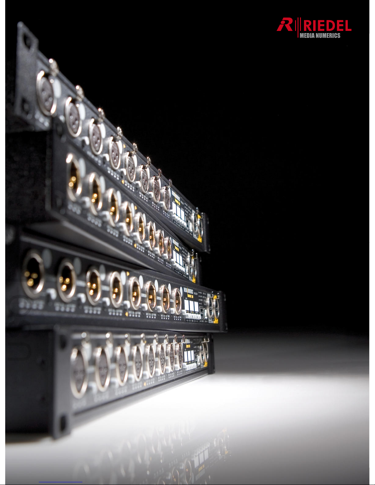
Page 1 of 88
RockNet 300
Operating Manual
Revision 1.20
USO RESTRITO

Page 2 of 88
ROCKNET 300
Installation and Operating Manual
This manual refers to firmware version 01.20
© Copyright 2008 by Media Numerics
All rights reserved.
No part of the RockNet300, its software RockWorks, or this Operating Manual may be reproduced or
distributed in any form or by any means without the prior written authorization of Media Numerics Ltd.
All rights reserved.
Disclaimer
All information is believed to be true and correct at time of print. Media Numerics Ltd. reserves the
right to make any changes, without notification, to their products and related manual. Media Numerics
makes no warranty of any kind with regards to this material, including the implied warranties of merchantability and fitness for a particular purpose. Media Numerics shall not be liable for errors contained herein or for incidental or consequential damage in connection with the furnishing, performance
or use of this material.
Trademarks
Media Numerics® is a registered trademark of Media Numerics Ltd. Other trademarks are the property
of their respective owners.
Contact us:
Media Numerics Ltd.
Rodenbacher Chaussee 6
63457 Hanau
Germany
phone: +49 (0) 7000 – ROCKNET
+49 (0) 7000 - 7625638
email: info@medianumerics.com
info.us@medianumerics.com
web: www.medianumerics.com
USO RESTRITO

Page 3 of 88
Content
Content.....................................................................................................................................3
Important Safety Instructions ............................................................................................6
Explanations of Symbols ....................................................................................................7
Declaration of Conformity...................................................................................................8
About RockNet.......................................................................................................................9
Auto-addressing...................................................................................................................9
Network Interface and Transmission Protocol..............................................................10
Build-in Redundancy.........................................................................................................10
Network Redundancy ...........................................................................................................10
Power Supply and Thermal Management ..............................................................................11
E
asy Installation.................................................................................................................11
Decentralized Audio Network..........................................................................................12
General Installation Instructions.....................................................................................13
Unpacking...........................................................................................................................13
Installation...........................................................................................................................13
Getting started .....................................................................................................................14
RN.300 Front Panel Layout .............................................................................................14
RN.300 Common Controls and Displays.......................................................................15
RN.300 Control Section........................................................................................................15
RN.300 Display and Push Button Details...............................................................................15
RN.300 Status Indicator Details ............................................................................................16
RN.300 Status Indication Table.............................................................................................16
RN.300 Network Section Details ...........................................................................................17
R
N.300 Control Section Common Operating Menu.....................................................18
Default Mode .......................................................................................................................18
Options Mode ......................................................................................................................19
Channel Mode .....................................................................................................................20
Channel Parameter Copy .....................................................................................................21
RN.300 Initial Power-up....................................................................................................22
Connect to Mains .................................................................................................................22
Self Test..............................................................................................................................22
Display................................................................................................................................23
Unity Gain ...........................................................................................................................23
Fan.....................................................................................................................................23
Network Wiring...................................................................................................................24
Firmware Check...................................................................................................................24
Link Indicators .....................................................................................................................25
Recommended Cables .........................................................................................................25
Network Configuration.......................................................................................................26
Synchronization .................................................................................................................26
Primary Sync Master Setting (Internal Oscillator)....................................................................27
Secondary Sync Master Setting (Internal Oscillator)...............................................................28
External Synchronization (Wordclock) ...................................................................................29
External Synchronization (AES/EBU Inputs of RN.331.DD and RN.333.DI)..............................30
Table of External Sync Options .............................................................................................30
C
hannel Routing Definitions ............................................................................................31
Quad assignment...............................................................................................................33
USO RESTRITO

Page 4 of 88
G
eneral Information ..................................
...........................................................................33
Quad Assignment of AES/EBU Devices ................................................................................34
Quad Assignment on the Front Panel....................................................................................35
Input Assignment (Add Quad)...............................................................................................35
Output Assignment (Drop Quad)...........................................................................................35
Error Handling....................................................................................................................36
Quad Assignment Errors ......................................................................................................36
Sync Setting Errors ..............................................................................................................36
80 Channel Mode..............................................................................................................37
General descrition................................................................................................................37
80 channel mode settings.....................................................................................................38
S
ervice Menu.....................................................................................................................39
RN.301.MI 8 Channel Microphone Pre-Amplifier / Line Input...............................40
RN.301.MI Features.............................................................................................................40
RN.301.MI Common Front Panel Facilities ............................................................................41
RN.301.MI Common Configuration........................................................................................41
RN.301.MI Input Section Details ...........................................................................................41
RN.301.MI Channel LED Description.....................................................................................41
RN.301.MI Control and Network Section Details ....................................................................42
RN.301.MI Front Panel Configuration............................................................................43
Channel Mode .....................................................................................................................43
RN.301.MI Channel Settings...........................................................................................43
Mute ...................................................................................................................................44
Gain....................................................................................................................................44
Phantom Power...................................................................................................................44
RN.301.MI Technical Specifications...............................................................................45
RN.302.LO 8 Channel Analog Line Output................................................................46
RN.302.LO Features ............................................................................................................46
RN.302.LO Common Front Panel Facilities............................................................................47
RN.302.LO Common Configuration.......................................................................................47
RN.302.LO Output Section Details ........................................................................................47
RN.302.LO Channel LED Description....................................................................................47
R
N.302.LO Front Panel Configuration...........................................................................49
Channel Mode .....................................................................................................................49
RN.302.LO Channel Settings..........................................................................................49
Mute ...................................................................................................................................49
Clip Level ............................................................................................................................50
RN.302.LO Output Redundancy............................................................................................50
RN.302.LO Technical Specifications..............................................................................51
RN.333.DI 8 Channel Digital Input ...............................................................................52
RN.333.DI Features .............................................................................................................52
RN.333.DI Common Front Panel Facilities.............................................................................53
RN.333.DI Common Configuration ........................................................................................53
RN.333.DI Input Section Details............................................................................................53
RN.333.DI Channel LED Description.....................................................................................53
RN.333.DI Control and Network Section Details.....................................................................54
RN.333.DI Front Panel Configuration............................................................................55
Channel Mode .....................................................................................................................55
RN.333.DI Channel settings............................................................................................55
Mute ...................................................................................................................................55
R
N.333.DI Technical Specifications...............................................................................56
RN.331.DD 4/4 Channel Digital In-/Output.................................................................57
RN.331.DD Features............................................................................................................57
RN.331.DD Common Front Panel Facilities ...........................................................................58
USO RESTRITO

Page 5 of 88
R
N.331.DD Common Configuration.......................
................................................................58
RN.331.DD Input section details ...........................................................................................58
RN.331.DD Channel LED Description ...................................................................................58
RN.331.DD Control and Network Section details....................................................................59
RN.331.DD Front Panel Configuration...........................................................................60
Channel Mode .....................................................................................................................60
RN.331.DD Channel Settings..........................................................................................60
Mute ...................................................................................................................................60
RN.331.DD Technical Specifications .............................................................................61
RN.332.DO 8 Channel Digital Output..........................................................................62
RN.332.DO Features............................................................................................................62
RN.332.DO Common Front Panel Facilities...........................................................................63
RN.332.DO Common Configuration ......................................................................................63
RN.332.DO Input section details ...........................................................................................63
RN.332.DO Channel LED Description ...................................................................................63
RN.332.DO Control and Network Section details....................................................................64
R
N.332.DO Front Panel Configuration ..........................................................................65
Channel Mode .....................................................................................................................65
RN.332.DO Channel Settings..........................................................................................65
Mute ...................................................................................................................................65
RN.332.DO Technical Specifications.............................................................................66
RN.341.MY Yamaha Interface Card .............................................................................67
RN.341.MY Features............................................................................................................67
RN.341.MY Important Safety Information......................................................................68
Warning ..............................................................................................................................68
Caution ...............................................................................................................................68
RN.341.MY Front Panel Sections...................................................................................69
Yamaha LS-9 (16) or (32) use...............................................................................................70
RN.341.MY Network Section ................................................................................................71
RN.341.MY Control & Data Section.......................................................................................71
R
N.341.MY general information......................................................................................72
RN.341.MY Installation.........................................................................................................72
RN.341.MY Channel Routing and Presets.............................................................................73
RN.341.MY Synchronization Options.....................................................................................74
Remote Control of RN.301.MI...............................................................................................75
RN.341.MY Edit Preset Window of RockWorks......................................................................76
RN.341.MY Individual Preset Configuration ...........................................................................77
Independent Gain ................................................................................................................78
RN.351.FI and RN.352.FO..................................................................................................81
RN.362.IR...............................................................................................................................82
RockNet300 Audio Network Sample Configuration...................................................83
Tour Sound Application (48in/16out, interfaces for 2 consoles)................................83
Warranty & Service.............................................................................................................85
Media Numerics Ltd. Limited Warranty..........................................................................85
How to get Service............................................................................................................85
Limitation of Warranty.......................................................................................................85
Appendix................................................................................................................................86
Technical Network Specifications...................................................................................86
Pin Outs .................................................................................................................................87
CAT5 Link ...........................................................................................................................87
Yamaha Head Amp Remote cable ........................................................................................87
All XLR connectors (female and male)...................................................................................88
USO RESTRITO

Page 6 of 88
Important Safety Instructions
• Read this manual carefully
• Please keep this user manual in a safe place during lifetime of RockNet products. The user
manual forms an integral part of the RockNet system.
• Heed all warnings
• Follow all instructions
• Do not use the RockNet system near water.
• Clean only with dry cloth.
• Do not block any ventilation openings and make sure an installation enclosure (e.g. Flight
case) has sufficient cool air flow.
• Do not install near any heat sources such as stoves, radiators or any devices that produces
heat.
• Protect the power cord from being walked on, pinched or damaged in any other way.
• The RockNet network and its devices may only be used in accordance with the information
provided in this manual. Before and during usage of the RockNet system please ensure that
all recommendations, especially safety recommendations as detailed in this manual are adhered to.
• Do not place the RockNet device on an unstable cart, stand, tripod, bracket or table. This de-
vice may fall, causing serious injury and serious damage to the system itself.
• Disconnect RockNet devices from mains power when unused for a long period of time.
• Refer all servicing to qualified personnel. Servicing is required when:
o the power inlet has been damaged
o liquid has been spilled or objects have fallen into the RockNet device
o the device has been drooped or suffered from damage in any other way
o the device shows a distinct change from its normal function, performance or appear-
ance.
• Reduced Air Flow - Installation of the equipment in a rack should be such that the amount of
air flow required for safe operation of the equipment is not compromised. Confirmed environment: E1, E2, E3 and E4.
• Mechanical Loading - Mounting of the equipment in the rack should be such that a hazardous
condition is not achieved due to uneven mechanical loading.
• The 19” devices must be earthed by connecting to a correctly wired and earthed power outlet.
The power cord supplied with the device is wired as shown:
o Green/Yellow = Earth
o Blue = Neutral
o Brown = Live
USO RESTRITO
Page 7 of 88
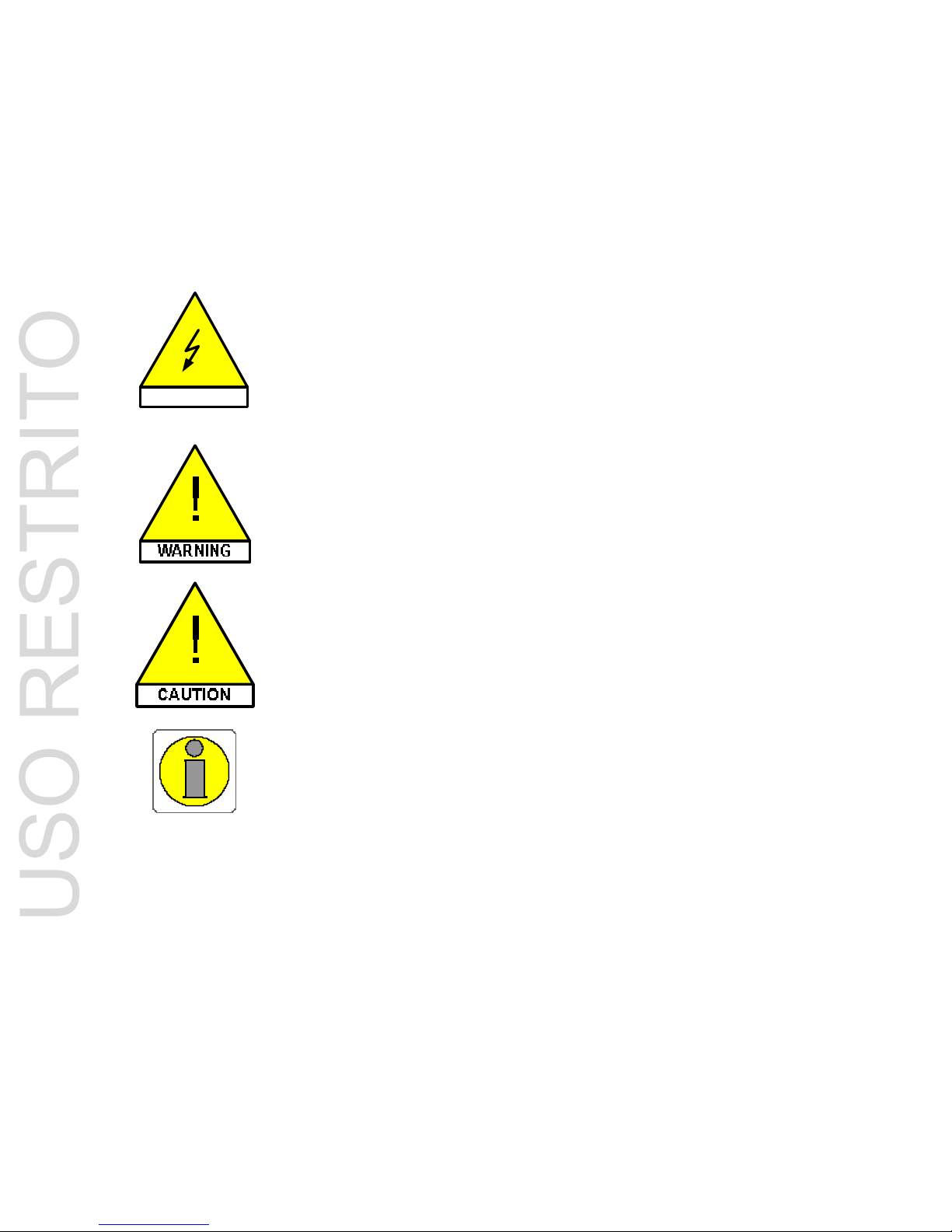
Explanations of Symbols
The following safety icons are used to indicate hazards and provide cautionary information in relation
to the handling and use of the equipment.
VOLTAGE
This symbol indicates high AC voltage from
power outlets (90V~ to 264V~ @ 50Hz or 60Hz).
A risk of injury from electric
shock exists if the instructions provided are not followed:
DO NOT OPEN THE ENCLOSURE OF THE PRODUCT!
This symbol indicates the presence of electric
shock or any other hazards.
A potential risk of injury from
electric shock or any other
hazards exists if the instructions provided are not followed.
This symbol indicates possible internal or external product damage.
This symbol indicates an important recommendation of use.
USO RESTRITO

Page 8 of 88
Declaration of Conformity
Media Numerics Ltd.
Rodenbacher Chaussee 6
63457 Hanau
Germany
Declare that the products
Equipment Type: Digital Audio Network
Family Name: RockNet
Model Names: RN.301.MI
RN.302.LO
RN.331.DD
RN.332.DO
RN.333.DI
RN.341.MY
RN.351.FI
RN.352.FO
RN.362.IR
are conform to the requirements of the EMC Council Directive 89/336/EEC as amended by
92/31/EEC, comprising the harmonized standards:
EN 55103-1:1997 Electromagnetic Compatibility – Product Family Standard for Audio, Video,
Audio-Visual and Entertainment Lighting Control Apparatus for Professional Use, Part 1: Emissions
and
EN 55103-2:1997 Electromagnetic Compatibility – Product Family Standard for Audio, Video,
Audio-Visual and Entertainment Lighting Control Apparatus for Professional Use, Part 2: Immunity
and the Low Voltage Directive EEC as amended by 93/68/EEC , comprising the harmonized standard:
EN 60065:2001 Safety Requirements – Audio, Video and Similar Electronic Apparatus
The products are manufactured by a DIN EN ISO 9001:2000 certified manufacturer.
The operating conditions and application environments presupposed in the Operating Manual are to
be kept accordingly.
Hanau, 2008-04-01
Matthias Knoth
Chief Technology Officer
USO RESTRITO
Page 9 of 88
About RockNet
RockNet is a real-time, low latency audio distribution network tailored to tour and installed sound applications.
RockNet provides a universal solution to almost any imaginable audio distribution challenge and behaves very much like a traditional analog active split system. It conveys 160 channels of 24bit/48kHz
audio based on CAT.5 interconnections.
RockNet products are designed for heavy duty road use. Their ruggedized steel enclosures resemble
the look and feel of a modular stagebox.
The network consists of various 19”/1RU I/O devices and a particular interface card for Yamaha host
products which make those Yamaha products part of the RockNet audio network.
There is no particular order of I/O devices required within a RockNet audio network. Any device can
be placed at any location.
Any input signal is anywhere available in the RockNet audio network.
The 160 channels are inputs into the network from either RN.301.MI microphone preamp/line input,,
RN.333.DI AES/EBU inputs or the input section of the RN.341.MY Yamaha interface cards.
The number of outputs is in practical terms unlimited although limited to 768. This offers the opportu-
nity to do as many splits as required in real world applications.
All connectors (except power, wordclock BNC and GPIO) are entirely gold-plated
The circuit design is streamlined to ultra low noise and minimum distortion to meet the highest de-
mands in audio quality.
Auto-addressing
RockNet300 works auto-addressing.
A
s soon as the devices are powered-up and the Network Sections are connected via CAT.5 (from Link
Output to Link Input of the neighbour device) the connected devices start communicating with each
other. The communication is based on internal unique device addresses that are similar to MAC addresses. By using these internal addresses the devices of a network “learn” what devices the network
consist of.
The front panel has a display named DEVICE ID. The setting of the device ID on the front of the device has no technical meaning. The network works with no device ID assigned or with several (or all)
devices having the same device ID. The DEVICE ID display is used to visually identify the devices of a
RockNet audio network.
Furthermore this ID is used by the included online remote control software RockWorks to identify individual devices on the screen.
The auto addressing functionality allows extremely flexible network build-up and extension in combination with the ring redundancy and the fact that there is no particular order of device types to build a
RockNet audio network.
USO RESTRITO

Page 10 of 88
Network Interface and Transmission Protocol
RockNet is NOT based on Ethernet even though it uses CAT.5 cables.
The RockNet transport protocol is proprietary and regular Ethernet products can NOT be implemented
in a RockNet audio network.
No particular IT or computer networking know-how is needed to setup and operate RockNet.
The RockNet RN.300 Network Interface incorporates two Media Numerics’ proprietary core technolo-
gies in order to enable RockNet to carry 160 channels of 24bit/48kHz audio over a single CAT.5 cable
in a redundant ring topology:
- LATERAL™
Ultra low latency asynchronous data transmission enables RockNet to support various redundant
network topologies and to provide real-time, isochronous data transport in conjunction with packetized data such as TCP/IP. The data rate is 400 Mps on CAT5 cable and the number of nodes is
infinite, though limited to 99 for practical reason.
- CONCRETE™
Clock recovery and jitter rejection utilizes a unique digital PLL structure. Jitter magnitude, spectrum
and probability distribution are de-randomized by a sophisticated digital modulation scheme, result-
ing in an extremely high jitter rejection and zero jitter build-up through the network.
All devices can be configured intuitively by front panel push buttons.
A system check can be performed within a few seconds per each device even without using a com-
puter.
Build-in Redundancy
RockNet incorporates a streamline redundancy concept on device and network level.
N
etwork Redundancy
The network interface of each device features two Ethercon© RJ45 interconnections for fail-save
transmission of audio signals on CAT.5 infrastructure. Two network connectors are used to link to a
neighbour device in a redundant ring topology. They can also be used to provide a parallel link in case
of point to point applications.
Based on the redundant ring topology, RockNet forms a self-healing network in case of connection
failures between two devices.
The 160 channels travel clockwise and counter clockwise simultaneously through the ring.
A connection failure between two devices does not affect the audio transmission or system integrity.
The ring is self-healing for single connection failures and offers significant advantages in performance,
consistency and flexibility.
RockNet automatically detects a failure described above and reconfigures the network links to handle
this problem without affecting the remaining audio network.
The network redundancy mechanism (in conjunction with the auto addressing feature) also offers the
opportunity to open the ring of an active audio network (e.g. during a running show) and easily link a
new RockNet device into the ring without interrupting the audio signal.
USO RESTRITO
Page 11 of 88
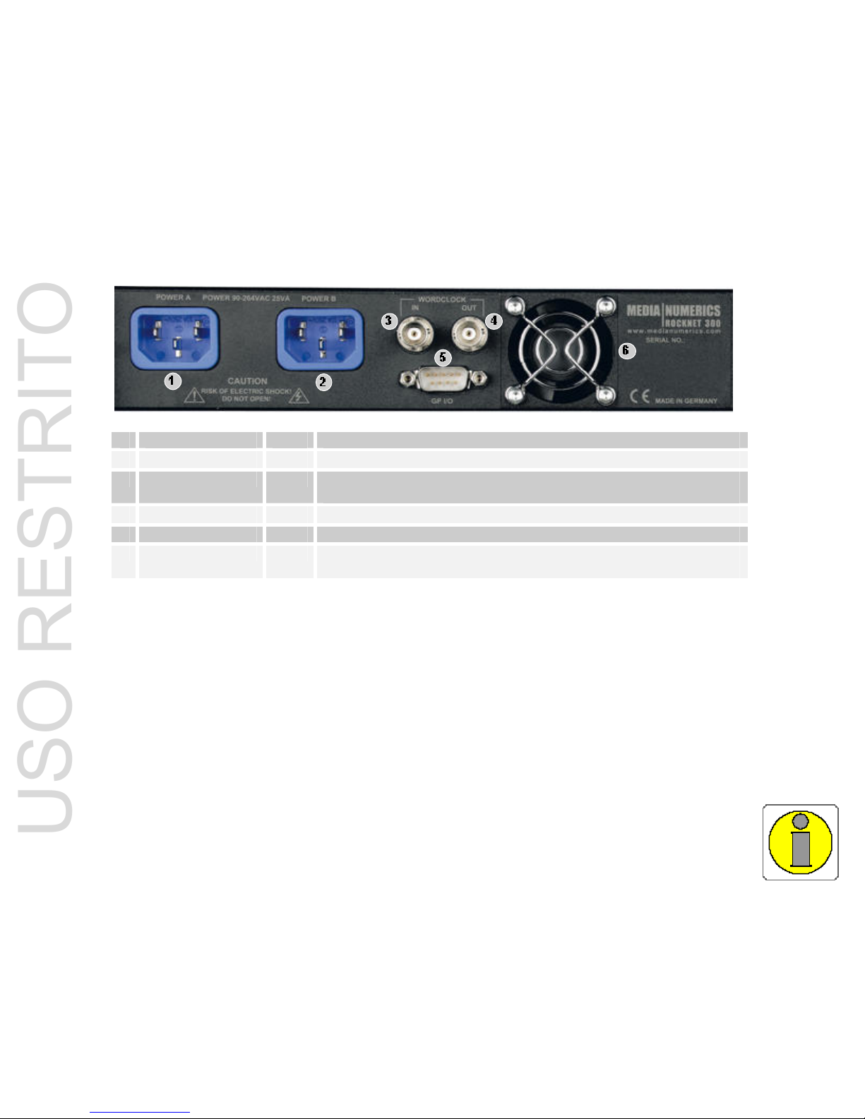
P
ower Supply and Thermal Management
Ro
ckNet devices feature redundant switch-mode power supplies suitable for world-wide operation.
The power supplies are modular and therefore easy to replace in case of failure.
The replacement of power supplies is done by Media Numerics Ltd. or one of its authorized distribu-
tors or dealers and may under no circumstances be done by the user.
Two locking IEC connectors on the back panel of the device are standard.
Built in silent running fans add to the component reliability and enable ultimate rack space efficiency.
1 Power Supply A IEC connect via locking IEC connector of provided power supply cord
2 Power Supply B IEC connect via locking IEC connector of provided power supply cord
3 Wordclock IN BNC connect via BNC for external sync of RN.300 device (Sync Master
only)
4 Wordclock OUT BNC connect via BNC for synchronizing external equipment to RN.300
5 GP I/O DB9 for future use, currently no functionality
6 Fan permanent silent running fan if device is connected to mains
power
Easy Installation
RockNet is an integrated system that does not require any third party products.
O
nly two types of cables are necessary to hook up a network:
• microphone cables with XLR (male/female) and
• CAT.5 network cables with RJ45 (Ethercon®)
RockNet devices do not require breakout panels or any special cables and connectors.
Up to 99 devices can easily be added to a single network.
All configuration information is stored in the device, e.g. Quad assignment, channel parameters, chan-
nel and device labels (via RockWorks), sync settings, etc.
USO RESTRITO
Page 12 of 88
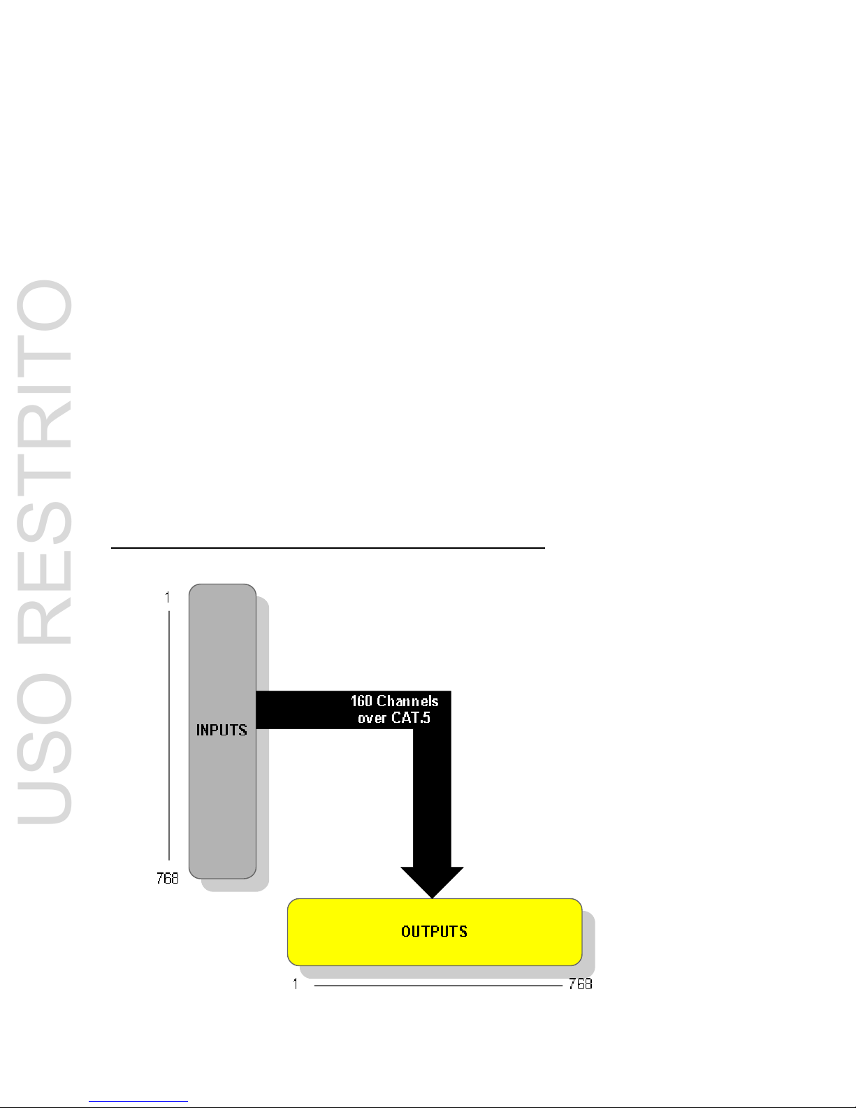
Decentralized Audio Network
RockNet is a genuine audio network platform, designed purposely for live sound applications and optimized for audio contribution and distribution.
RockNet provides a virtual distributed audio matrix with a capacity of:
• 768 inputs
• 768 outputs
• 160 transport channels over CAT.5
In multiple stage setups the high amount of inputs can be used to build an audio network that covers
all stages with only one FOH console and multiple monitor mixing consoles.
The Snapshot functionality of the included online remote control software RockWorks (please see the
RockWorks Operating Manual) allows to partially activate a network that carries 160 audio channels
while having up to 768 inputs.
This functionality can also be used in any application where more than 160 inputs are required in total
but not more than 160 inputs are active at the same time.
The high amount of outputs can be used for large drive systems and to distribute audio to several
destinations within one infrastructure. It offers an almost unlimited number of splits in practical terms.
Graphical symbolization of the RockNet virtual distributed audio matrix
USO RESTRITO
Page 13 of 88
General Installation Instructions
Please familiarize yourself with the device and its operation and read this Operating Manual carefully.
Do not install any RockNet RN.300 device in a location subjected to excessive heat (such as direct
theatrical lighting or direct sunlight), dust or mechanical vibration.
Unpacking
•
Save all the packing materials. They will prove valuable should it become necessary to transport or ship this product.
• Please inspect the RockNet device carefully for any signs of damage incurred during transpor-
tation. It has undergone stringent quality control inspection and every possible effort has been
made to ensure that it left the factory in perfect condition.
• If the product shows any signs of damage, please notify the transportation company without
delay. Do not connect a damaged device to AC power outlets.
• Only the consignee may institute a claim against the carrier for damage during transportation.
• If necessary, contact your supplier or as a last resort, your local Media Numerics distributor,
dealer or agent, who will fully cooperate under such circumstances.
Installation
R
ockNet I/O devices (except RN.341.MY Yamaha interface cards) are designed for 19” rack mount
installation. Please make sure that common installation basics are taken care of:
• Do not install any RockNet RN.300 device in a location subjected to excessive heat such as
direct theatrical lighting or direct sunlight
• Make sure sufficient airflow is granted
• Use RockNet devices in environmental temperature range between
0°C and 50°C or 32°F and 122°F
• Do not place any items on top of the RockNet device
• Do not place RockNet devices on uneven grounds
• Protect RockNet devices from mechanical and electrical shock
• Protect RockNet devices from mechanical vibration
• Protect RockNet devices from moisture and liquidity impact of any kind
• Protect RockNet devices from dust and dirt
USO RESTRITO
Page 14 of 88
Getting started
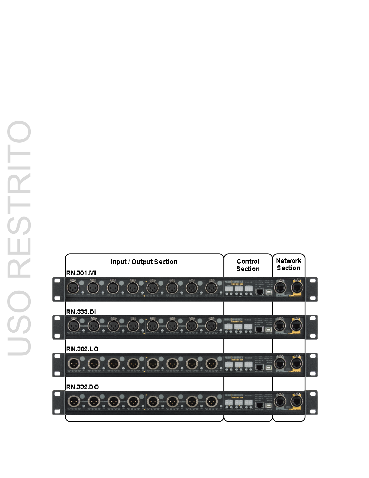
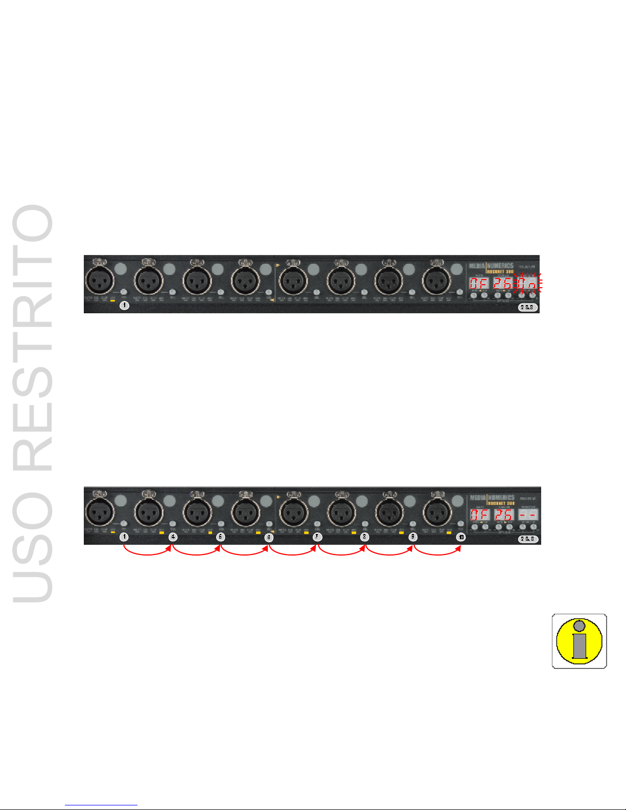
RN.300 Front Panel Layout
The layout of the front panel of RockNet RN.300 19” devices is divided into three sections (from left to
right):
• Input / Output Section
provides
- XLR connectors for Input or Output channels
- LED indicators for each channel
- channel select button (SEL)
- designation point per channel
• Control Section
provides
- three two-digit displays
- six push buttons to operate the three-level menu
- LED status indicators
- USB connector to connect to RockWorks
• Network Section
provides
- Ethercon® Link Input connector (grey)
- Ethercon® Link Output connector (yellow)
- Remote Power LED status indicators
- 10/100BT connector for additional Ethernet transport
USO RESTRITO
Page 15 of 88
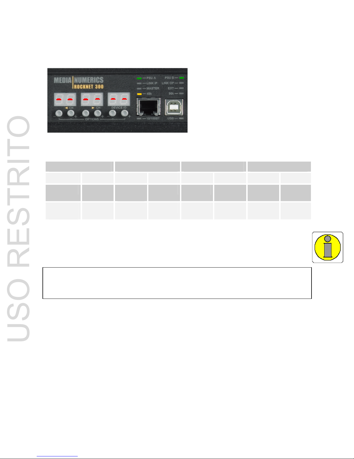
RN.300 Common Controls and Displays
RN.300 Control Section
RockNet 19” RN.300 I/O devices are equipped with a common local configuration interface which is
intuitive and easy to use.
The control section provides the controls to set up and configure the device and network without a
computer and provides LEDs to indicate the status of the device and the network.
The local configuration menus of RockNet have common and specific parts.
The control Section incorporates the displays and push buttons described below that are used for
intuitive operation of a three level menu. For more detailed information please refer to pages 18 to 20
of this manual.
• Default mode,
permanently active
displays:
- Quad routing information of the two or four Quads of the device
- Device ID number
• Channel mode,
momentary active (push SEL button)
displays:
- Channel parameters of the respective device:
RN.301.MI: MUTE GAIN PHANTOM
RN.302.LO: MUTE - - CLIP LEVEL
RN.331.DD: MUTE - - - RN.332.DO: MUTE - - - RN.333.DI: MUTE - - - -
• Options mode,
momentary active (push 4&5 and 8&9 simultaneously)
- general device and network settings:
Set Sync Master & select external sync source
Lock front panel operation
Display device temperature
Switch display off
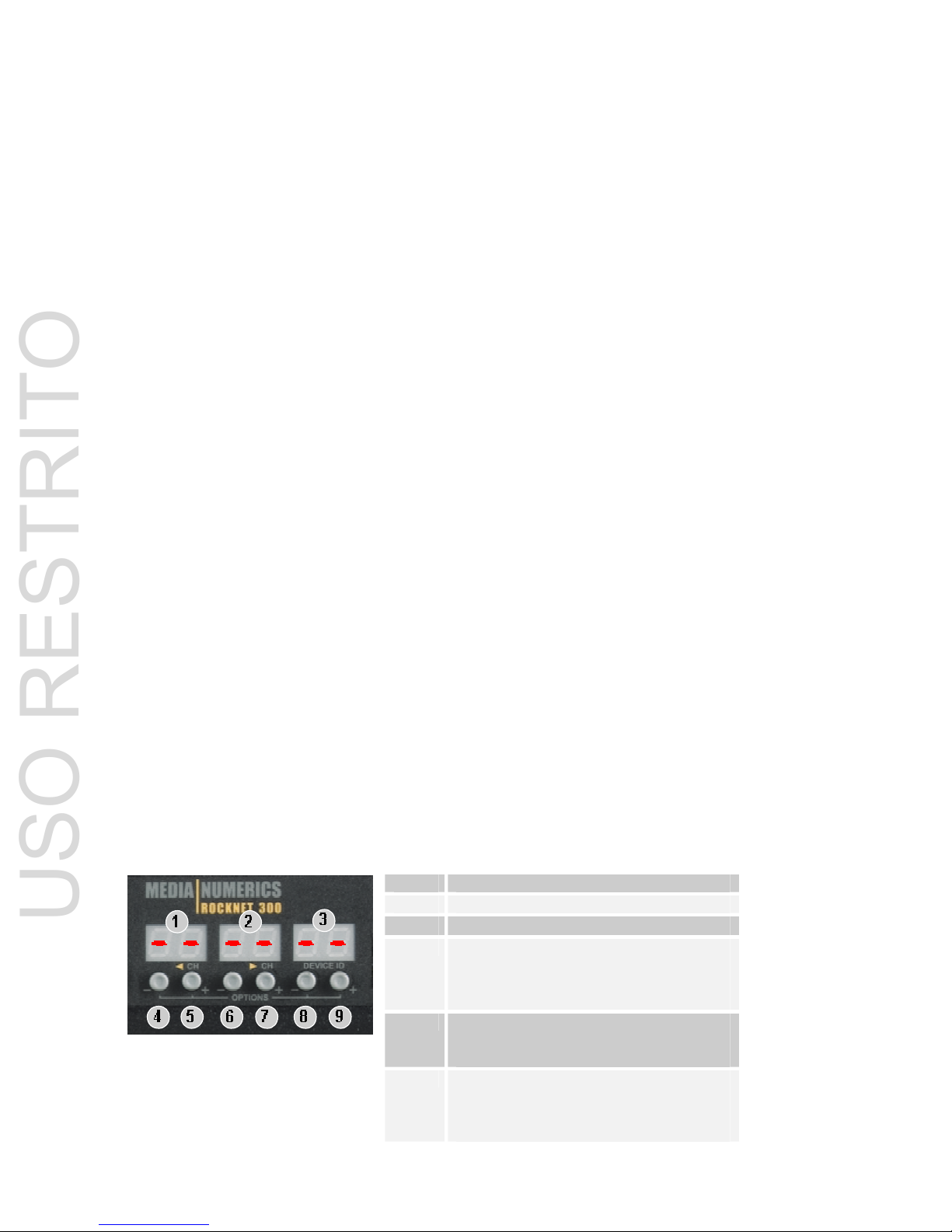
RN.300 Display and Push Button Details
The displays and push buttons are structured the same way for each device:
RN.300 Generic Control Section
1 Left-hand display
2 Middle display
3 Right-hand display
4 & 5 Push buttons to
- set left-hand Quad no.
- set channel parameter
- access & change OPTIONS menu
6 & 7 Push buttons to
- set right-hand Quad no.
- set channel parameters
8 & 9 Push buttons to
- set device ID
- set channel parameters
- access & change OPTIONS menu
USO RESTRITO
Page 16 of 88
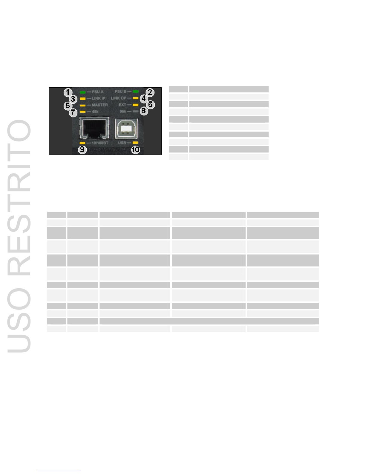
R
N.300 Status Indicator Details
Th
e status indicator LEDs of the control section are arranged in the same way on each 19” device
front panel:
1 PSU A Indicator
2 PSU B Indicator
3 LINK INPUT Indicator
4 LINK OUTPUT Indicator
5 Sync MASTER Indicator
6 EXT sync Indicator
7 SAMPL. FREQ 48kHz
8 SAMPL. FREQ 96kHz
9 10/100BaseT Port indicator
10 USB Port indicator
RN.300 Control Section Status Indicators
RN.300 Status Indication Table
Indicator Off Flashing Permanent
1 PSU A
not connected or
power failure
- power ok
2 PSU B not connected or
power failure
Power ok
3 LINK IP
LINK OP
no CAT.5 cable connected
to neighbor device
communication ok
Synchronization missing
communication ok
synchronization ok
4 LINK OP no CAT.5 cable connected
to neighbor device
5 MASTER device is sync slave non active sync master device is sync master
6 EXT no external sync config-
ured
external sync configured
sync signal not available
external sync configured
and sync signal available
7 48k 96k sampling rate - 48k sampling rate
8 96k 48k sampling rate - -
9 10/100BT Currently no function
10 USB USB cable not connected - USB cable connected
USO RESTRITO
Page 17 of 88
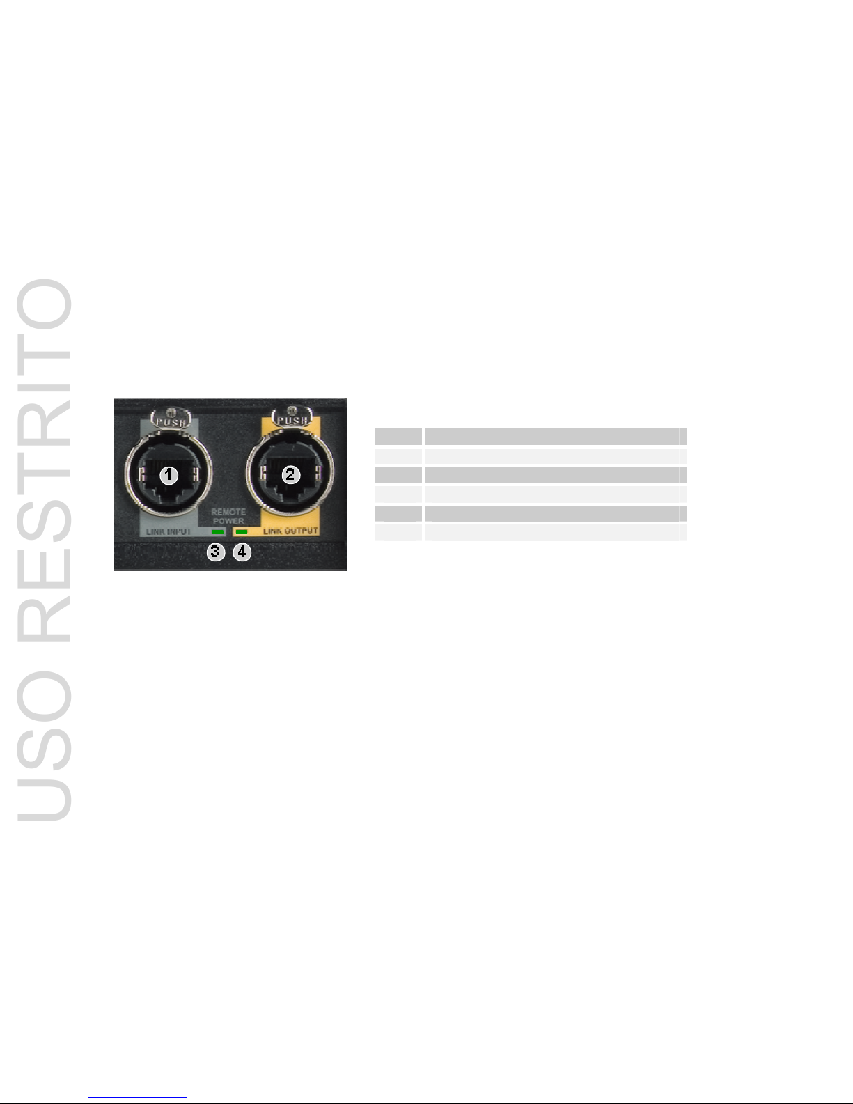
R
N.300 Network Section Details
Th
e Network Section provides the Link Input and Link Output Ethercon® connectors for the CAT.5
network infrastructure.
The Link Input is marked in grey and the Link Output is marked in yellow on all RN.300 devices.
In order to build an audio network the Link Output needs to be connected to the Link Input of the
neighbour device and so forth until the CAT.5 cable forms a ring and connects the last Link Output of
a neighbour device to the Link Input of the start device.
Two Remote Power status LEDs for the Input and Output respectively indicate the availability of Remote Power. The LEDs are permanently green if the remote power option is build into the respective
device.
This option is mandatory for the use of the RN.362.IR Inline Repeater which extends the length of a
CAT.5 link to max. 450m (1,500ft).
The RN.362.IR is a future Media Numerics product which is not described in this manual.
1 LINK INPUT Connector
2 LINK OUTPUT Connector
3 Remote Power Indicator Link Input *)
4 Remote Power Indicator Link Output *)
*) optional, for use of RN.362.IR
RN.300 Network Section
USO RESTRITO

Page 18 of 88
RN.300 Control Section Common Operating Menu
Default Mode
This is the display mode that is permanent active in order to show the essential information to operate
the network.
In default mode of the display Quad routing and device ID are displayed.
To change the Quad numbers or the device ID number push the two buttons underneath the respective display (for Quad number and channel allocation please see yellow arrows underneath displays)
until the display starts flashing.
As long as it is flashing the values can be changed by using one of the two buttons (+ or -) underneath
the respective display. The value increases or decreases in steps of 1 by each push or for speedy
operation hold the respective button. As soon as the button is released the display stops. At the end of
the range the display starts from the beginning (or end respectively).
In order to acknowledge the new value both buttons underneath the respective display need to be
pushed again until the display stops flashing.
In case the acknowledgement does not take place the former value is still valid and the display jumps
back to this value as soon as it stops flashing.
Left-hand display Quad number of four channels on the left-hand side of the front panel
(please see separation line and yellow arrow)
Factory preset: unassigned --
-
---
--
Middle display Quad number of four channels on the right-hand side of the front panel
(please see separation line and yellow arrow)
Factory preset: unassigned --
-
---
--
Right-hand display Device ID number
Factory preset: unassigned --
----
--
USO RESTRITO
Page 19 of 88
O
ptions Mode
Th
e Options Mode provides general device and network setups.
Pushing the two buttons underneath the left-hand and the right-hand display simultaneously gives
access to the Options Menu.
The Options Menu will be displayed temporary for approximately three seconds.
The first option displayed is the sync master setting.
Step through the options of the menu shown below by using the right button underneath the left-hand
display. By using the left button the menu is displayed in reverse order.
In order to change the values of a menu item push the two buttons underneath the right-hand display
simultaneously until the display starts flashing. Afterwards the value can be changed by using right or
left button underneath the right-hand display. The change needs to be acknowledged by pushing the
two buttons underneath the right-hand display again until the display stops flashing.
Options Mode Menu:
MA St
MA StMA St
MA St
defines the synch master of the entire RockNet audio network
OF
OFOF
OF
device is sync slave
PM
PMPM
PM
device is primary sync master
SM
SMSM
SM
device is secondary sync master
factory preset = OF
OFOF
OF
ES Yn
ES YnES Yn
ES Yn Only accessible if device is sync master: MA St PM
MA St PM MA St PM
MA St PM or SM
SM SM
SM
(use right button underneath right-hand display)
OF
OFOF
OF
sync source is internal oscillator
On
OnOn
On
external sync via wordclock
1 2 3 4 5 6 7 8
1 2 3 4 5 6 7 81 2 3 4 5 6 7 8
1 2 3 4 5 6 7 8 (RN.333.DI)
1 2 3 4
1 2 3 41 2 3 4
1 2 3 4 (RN.331.DD)
Numbers representing AES/EBU inputs from left (1111) to right (4444 or 8888)
factory preset = OF
OFOF
OF
For more information about network synchronization please refer to pages 26 to 29 of this manual.
LO Cd
LO CdLO Cd
LO Cd
locks the Front Panel operation
OF
OFOF
OF
front panel not locked
On
OnOn
On
front panel locked
(indicated by decimal points in all three displays)
factory preset = OF
OFOF
OF
tE MP
tE MPtE MP
tE MP
displays the temperature inside the device in ºC
80
8080
80 C
C C
Chhhh
Only accessible if device is sync master: MA St PM
MA St PM MA St PM
MA St PM or SM
SM SM
SM
(use right button underneath right-hand display)
On
OnOn
On
sets entire network to 80 channel mode
Of
OfOf
Of
Network is in 160 channel mode
factory preset = Of
OfOf
Of
dISP
dISPdISP
dISP
switches display and all LEDs off (except POWER LEDs)
On
OnOn
On
displays and LEDs are on
OF
OFOF
OF
displays and LEDs are off, except POWER LEDs
factory preset = On
OnOn
On
USO RESTRITO
Page 20 of 88
C
hannel Mode
Th
e Channel Mode of the display is used to show and adjust the channel parameters of each channel
of the device.
Channel Mode is a momentary function is accessible as long as the channel select button (SEL) be-
side the XLR connector of the respective channels is pushed.
The Channel Mode of each RockNet RN.300 device is described in detail in the respective device
section of this manual.
As soon as the SEL button is released the display goes back to default mode and shows Quad routing
and device ID.
The adjustment of the respective value (designation indicated above the respective display) is made
by simply using one of the two buttons underneath the display.
On and OF channel parameters (like MUTE and PHANTOM) can be toggled by using either one of the
two buttons.
GAIN and CLIP LEVEL adjustments are 1dB steps with each push. Increment is done by using the
right-hand button (+) and decrement is done by using the left-hand button (-). For speedy operation
the respective button can be held. The display stops at the end of the range or at the time of releasing
the button.
All settings are immediately active.
RN.301.MI
Left-hand display
MUTE
OF
OFOF
OF
channel is not muted
On
OnOn
On
channel is muted
Middle display
GAIN
-6
-6-6
-6 … 66
6666
66 dB
Gain in dB in 1 dB steps
factory preset 0000dB
Right-hand display
PHANTOM
OF
OFOF
OF
+48V Phantom Power off
On
OnOn
On
+48V Phantom Power on
Channel will be muted for approximately 3 seconds at Phantom Power switch (on and
off).
RN.302.LO
Left-hand display
MUTE
OF
OFOF
OF
channel is not muted
On
OnOn
On
channel is muted
Right-hand display
CLIP LEVEL
-9
-9-9
-9 … 24
2424
24 dBu
Level in 1dB steps
factory preset 24
2424
24dBu
RN.332.DO / RN.332.DO / RN.333.DI
1x AES/EBU channel per XLR
Left-hand display
MUTE
OF
OFOF
OF
channel is not muted
On
OnOn
On
channel is muted
USO RESTRITO
Page 21 of 88
C
hannel Parameter Copy
Th
e channel mode provides the opportunity to copy the value of a single channel parameter from one
channel to another (or to several channels) of the same device.
Push the channel select button (SEL) of the designated channel (e.g. most left-hand channel [1]). Adjust the designated parameter to the desired value (e.g. MUTE on) by using the respective button underneath the MUTE display.
Afterwards push and hold both buttons underneath the MUTE display [2 & 3] until the display flashes
while still holding the SEL button [1].
As soon as the display starts flashing the SEL button [1] can be released while still holding the two
buttons of the MUTE display [2 & 3].
Now the value (MUTE O
OOOnnn
n) can be copied to any other channel of the device by simply pushing the
SEL button ([4], [5], [6], [7], [8], [9], [10]) of the channel the parameter shall be copied to. At each push
of a SEL button the MUTE display will show the two horizontal bars (--
-
---
--) to indicate the successful
copy of the value.
After the copy is finished release all buttons.
The copy function works for all channel parameters:
- MUTE,
- GAIN,
- PHANTOM,
- CLIP LEVEL
Only one parameter can be copied at a time.
USO RESTRITO

Page 22 of 88
RN.300 Initial Power-up
This chapter describes the appearance and indications shown after powering an un-configured device
or network.
Connect to Mains
For safety reasons RockNet devices are NOT equipped with mains switches. After connecting at least
one power inlet to mains the device will start operating. RockNet is equipped with 2 (two) independent
(= redundant) power supplies and individual locking IEC connectors. These cables will protect the
individual power cords from accidental removal. Only use these power cables to operate the device.
For unlocking and disconnecting push the yellow button on top of the connector.
Before connecting to mains check the power cord and connectors for damage. Don’t use the power
cord if the isolation or one of the connectors is damaged or shows blank metal wires.
USING DAMAGED POWER CORDS CAN ENDANGER YOUR LIFE!
1 2
1 Push to release
2 Push to release
Self Test
After connecting at least one mains socket with mains net the device will automatically perform a self
test. This test will check the entire device and all LED indicators. The device firmware will be displayed
in the 7 segment displays at the end of the self test. A checked device will appear like this:
Display test
Firmware Version
VOLTAGE
USO RESTRITO
Page 23 of 88
D
isplay
Th
e system display will identify an un-configured device by horizontal bars on all displays.
RN.300 Display of an un-configured device
RN.300 devices have the following factory default settings:
RN.301.MI RN.302.LO RN.332.DO RN.333.DI
MUTE: OFF MUTE: OFF MUTE: OFF MUTE: OFF
GAIN: 0dB CLIP
LEVEL:
24dBu
PHANTOM
POWER:
OFF
Unity Gain
The factory default setting of 0dB gain at the RN.301.MI microphone preamp / line level input and
+24dBu clip level at the RN.302.LO is the so called unity gain setting. With these settings a signal will
pass the network with no level adjustments.
EXAMPLE:
An input signal of 10dBu fed into the RN.301.MI will occur at a level of 10dBu at the RN.302.LO output
if the gain adjustment at the RN.301.MI is set to 0dB and the level adjustment at the RN.302.LO is set
to +24dBu.
The input level can be attenuated to -6dB and the output level can have a maximum attenuation of
33dB (to -9dBu).
The maximum output level of an RN.302.LO is +24dBu.
The maximum input level of an RN.301.MI is 30dBu (if the input attenuation is adjusted to -6dB).
Fan
A ventilation fan mounted on the rear panel will ensure permanent proper cooling as soon the device
is connected to mains.
USO RESTRITO
Page 24 of 88
Network Wiring
Firmware Check
Before wiring the network by connecting the Link Output of the first RockNet RN.300 device with the
Link Input of the neighbour device via CAT.5 cable check the firmware version of each device that
shall be part of the network.
IMPORTANT: The firmware version of each device in the network needs to be the identical.
Check the firmware version either by powering each device up and carefully watch the firmware ver-
sion displayed after the self test or by using RockFlash.
RockFlash is part of RockWorks and enables easy firmware updates of each device via a PC/Laptop
connected with USB. Please see the RockWorks manual for further details of how to use RockFlash.
If you do firmware updates please the remote HA-cable of RN.341.MY interface cards needs to be
removed first. In case you are going to update any of the 19” RockNet devices please do not push any
buttons of the front panel facilities during the update process.
The Yamaha host product needs to be re-started after the RN.341.MY interface card has been updated.
Double-click on the RockFlash icon on the desktop of your PC/Laptop and connect the USB cable to
the RockNet device.
In case this is the first time you connect a RockNet device to your PC/Laptop MS-Windows will ask
you to install the correct USB driver. Please simply follow the instructions provided in the MS Windows
installation assistant.
The USB driver installation process needs to be repeated for any of your USB connectors of your
PC/Laptop. This is a MS-Windows characteristic.
The following window will finally appear:
The displayed “Current Firmware Version” needs to be identical for all RockNet devices in the network.
If this is not the case please update the respective devices by clicking the “update Firmware” button in
the window shown above. Otherwise the network will not be operational since the device communication cannot be established.
USO RESTRITO

Page 25 of 88
L
ink Indicators
Ro
ckNet uses proprietary technologies to transport 160 channels of 24bit/48kHz audio over a single
CAT.5 cable. Each RockNet RN.300 device is equipped with a link input (grey) and a link output (yellow) Neutrik© Ethercon® connector. After connecting all devices of the audio network with each other
by connecting LINK OUT of one device with LINK IN of the neighbour device a so called redundant
ring network has been formed.
A successfully established link is indicated by flashing LED link indicators.
LINK INDICATORS FLASHING
communication to next device established but net-
work not yet synchronized
LINK INDICATORS PERMANENT
network communication and synchronization established
Recommended Cables
It is strongly recommended to use network cables fulfilling the CAT.5 STP or higher CAT specifications
in conjunction with the use of Neutrik© Ethercon connectors.
Standard RJ45 connectors may be used for test setups. In this case the RJ45 release lever is used to
disconnect the RJ45 connector.
RockNet requires the following audio network CAT cabling:
• CAT.5 or better
• STP cable (in case of CAT.5 or CAT.6)
• Max distance between units 150m or 500ft
• Max cable attenuation 19dB @ 100MHz (100m)
• Do NOT use LOW SKEW cables!
• UTP cable may be used but the use is not recommended
USO RESTRITO

Page 26 of 88
Network Configuration
Synchronization
Like any digital network RockNet needs a defined clocking source. Each RockNet device is able to:
• generate the system clock itself
- no specific external clock or synchronization unit is needed
- RN.300 device takes its internal oscillator as the internal clock source
• use an external clocking source
- either connect a wordclock input to the respective device or
- use one of the AES/EBU inputs as sync source (RN.331.DD and RN.333.DI)
Only one Primary and one Secondary Sync Master are allowed in a RockNet audio network.
Missing synchronization of the audio network is indicated by flashing Link LEDs in the status indication
section on the front panel of the devices.
As soon as the network is synchronized the Link LEDs are permanent (yellow).
Use the Options Menu to set the Primary and/or Secondary Sync Master of the network. Each Sync
Master type can only be configured on different dedicated devices.
In a newly build network it is not possible to configure two different devices as being the Primary or
Secondary Sync Master. In case two (or more) already as Primary or Secondary Master configured
devices are linked to a network the Link LEDs of all devices will be flashing and the number of Primary
Master settings needs to be reduced to maximum one single Primary and one single Secondary Sync
Master in the network. Devices configured to be Primary Master are indicated by a permanent master
LED on the front panel. Usually the Secondary Master shows a flashing master LED on the front
panel.
In case of a Synch Master switch-over which is always accompanied by a short audio interruption
(network is muted in order not to give out any noise due to temporary synch loss) the Secondary
Synch Master shows a permanent master LED.
If the Primary Synch Master comes back into the network the synchronization will not switch back to
the Primary Master in order to avoid a loss of audio (short interruption) and the master LED on the
front panel of the Primary Synch Master flashes.
Pushing the two buttons underneath the left-hand and the right-hand display simultaneously gives
access to the Options Menu.
The Options Menu will be displayed temporary for approximately three seconds.
The first option displayed is the Sync Master setting.
The description of the network synchronization on the following pages assumes that the Primary Sync
Master is set before the Secondary Sync Master is configured. If this sequence of events is reversed,
i.e. the Secondary Sync Master is set before the Primary Sync Master the following changes occur:
- as soon as the SM is configured the Link LEDs stop flashing and are permanent
- after configuring the PM the Master LED of the PM will be flashing
USO RESTRITO
Page 27 of 88
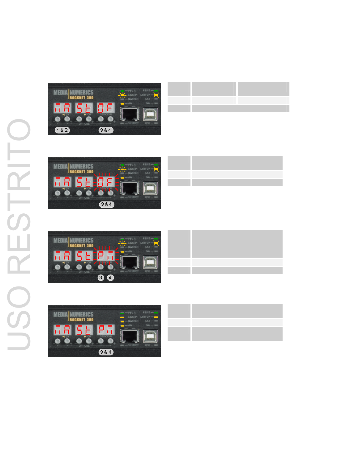
P
rimary Sync Master Setting (Internal Oscillator)
Fo
llow the instructions below to set the Primary Sync Master of the network with internal oscillator as
sync source.
1 & 2
3 & 4
Push and hold
Push and hold
simultaneously
Link LEDs flashing
3 & 4 Push and hold until display
starts flashing
Link LEDs flashing
3
4
Push to change value from off
to PM
Push to change value from off
to PM
Link LEDs flashing
3 & 4 Push and hold until display
stops flashing
Link LEDs permanent and Mas-
ter LED on.
MA ST OF
MA ST OFMA ST OF
MA ST OF This setting indicates device is set to be a sync slave.
MA ST PM
M
A ST PMMA ST PM
MA ST PM This setting indicates device is set to be the primary sync master of the RockNet au-
dio network.
Permanent Link indicators on the control section now indicate a synchronized audio network.
USO RESTRITO
 Loading...