

Riedel Performer CR-4, Performer C3, Performer CR-2, Performer CD-2, Performer CW-2 User Manual
...
Digital Partyline
CR-4 • CR-2 • C3 • CD-2
CW-2 • C31 • C44 / C44plus
User Manual
USO RESTRITO

© 2007 Riedel Communications GmbH & Co KG. Alle Rechte vorbehalten.
Dieses Handbuch ist urheberrechtlich geschützt. Das Kopieren, Vervielfältigen, Übersetzen oder Umsetzen in irgendein elektronisches Medium oder maschinell lesbare Form im
Ganzen oder in Teilen ohne vorherige schriftliche Genehmigung von Riedel ist nicht gestattet. Riedel übernimmt keine Gewähr für die Richtigkeit des Inhalts dieses Handbuchs. Die
Rechte an anderen in diesem Handbuch erwähnten Marken- und Produktnamen liegen bei ihren Inhabern und werden hiermit anerkannt.
© 2007 Riedel Communications GmbH & Co KG. All rights reserved.
Under the copyright laws, this manual may not be copied, in whole or in part, without the written consent of Riedel. Every effort has been made to ensure that the information in
this manual is accurate. Riedel is not responsible for printing or clerical errors. All trademarks are the property of their respective owners.
USO RESTRITO

PERFORMER Digital Partyline, User Manual, Version 2.30
TABLE OF CONTENTS
1 SAFETY INSTRUCTIONS 6
2 GENERAL 7
2.1 Performer CR-4 / CR-2 Master Station ............................................................................................................................. 7
2.2 Performer CD-2 Desktop Speaker / Headset Station...................................................................................................... 7
2.3 Performer C3 Digital Beltpack ........................................................................................................................................... 7
2.4 Performer CW-2 Digital Wall Mount Speaker / Headset Station .................................................................................... 8
2.5 Performer C31 Split Box..................................................................................................................................................... 8
2.6 Performer C44/C44plus System Interface....................................................................................................................... 8
3 PERFORMER CR-4 / CR-2 MASTER STATION 9
3.1 Getting Started.................................................................................................................................................................... 9
3.2 User Elements Front ........................................................................................................................................................... 9
3.2.1 Microphone Connector ......................................................................................................................................10
3.2.2 Headset Connector ............................................................................................................................................10
3.2.3 Headset Knob (2 Functions).............................................................................................................................. 10
3.2.4 SIDE TONE Adjustment Headsets .....................................................................................................................10
3.2.5 LISTEN (Latching) ............................................................................................................................................... 11
3.2.6 LISTEN Knob (2 Functions)................................................................................................................................11
3.2.7 TALK A/B (Auto / Momentary) ..........................................................................................................................11
3.2.8 CALL (2 Functions) ............................................................................................................................................. 12
3.2.9 GPI (Momentary)................................................................................................................................................. 13
3.2.10 M/Kill (Momentary)............................................................................................................................................ 13
3.2.11 SA Stage Announcement (Momentary) ............................................................................................................ 14
3.2.12 M/MUTE (Latching) ............................................................................................................................................ 14
3.2.13 PGM Level Control.............................................................................................................................................. 14
3.2.14 Speaker Volume Knob (2 Functions) ................................................................................................................ 15
3.3 User Elements Rear.......................................................................................................................................................... 16
3.3.1 Power Connector ................................................................................................................................................16
3.3.2 SUB D 15 Connector ..........................................................................................................................................16
3.3.3 PGM IN Connector.............................................................................................................................................. 17
3.3.4 SA OUT Connector .............................................................................................................................................. 17
3.3.5 Upstream Connector .......................................................................................................................................... 17
3.3.6 Downstream Connector ..................................................................................................................................... 17
3.3.7 Headset XLR Connector..................................................................................................................................... 17
3.3.8 DIP Switch CR-4 / CR-2...................................................................................................................................... 18
3.4 Specifications.................................................................................................................................................................... 19
4 PERFORMER CD-2 DESKTOP SPK/HS STATION 20
4.1 Getting Started.................................................................................................................................................................. 20
4.2 User Elements Front ......................................................................................................................................................... 20
4.2.1 Microphone Connector ......................................................................................................................................21
4.2.2 Headset Connector ............................................................................................................................................21
4.2.3 Headset Knob (2 Functions).............................................................................................................................. 21
4.2.4 SIDE TONE Adjustment Headsets .....................................................................................................................21
4.2.5 LISTEN (Latching) ............................................................................................................................................... 22
4.2.6 LISTEN Knob (2 Functions)................................................................................................................................22
4.2.7 TALK A/B (Auto / Momentary) ..........................................................................................................................22
4.2.8 CALL (2 Functions) ............................................................................................................................................. 23
4.2.9 GPI (Momentary)................................................................................................................................................. 24
4.2.10 M/Kill (Momentary)............................................................................................................................................ 24
4.2.11 SA Stage Announcement (Momentary) ............................................................................................................ 25
4.2.12 M/MUTE (Latching) ............................................................................................................................................ 25
4.2.13 PGM Level Control.............................................................................................................................................. 25
4.2.14 Speaker Volume Knob (2 Functions) ................................................................................................................ 26
4.3 User Elements Rear.......................................................................................................................................................... 27
4.3.1 Power Connector ................................................................................................................................................27
Page 3
USO RESTRITO
PERFORMER Digital Partyline, User Manual, Version 2.30
4.3.2 SUB D 15 Connector ..........................................................................................................................................27
4.3.3 PGM IN Connector.............................................................................................................................................. 28
4.3.4 SA OUT Connector .............................................................................................................................................. 28
4.3.5 Upstream Connector .......................................................................................................................................... 28
4.3.6 Downstream Connector ..................................................................................................................................... 29
4.3.7 Headset XLR Connector..................................................................................................................................... 29
4.3.8 DIP Switch CD-2.................................................................................................................................................. 30
4.4 Specifications.................................................................................................................................................................... 31
5 PERFORMER C3 DIGITAL BELTPACK 32
5.1 Get Started ........................................................................................................................................................................ 32
5.2 User Elements Top............................................................................................................................................................ 32
5.2.1 Error LED (red).................................................................................................................................................... 32
5.2.2 CALL LED (orange) .............................................................................................................................................33
5.2.3 Channel A/B LED (green) ..................................................................................................................................33
5.2.4 Power LED........................................................................................................................................................... 33
5.2.5 Channel Knob (2 Functions).............................................................................................................................. 33
5.2.6 CALL Key .............................................................................................................................................................34
5.2.7 GPI Key (Formerly SCALL).................................................................................................................................. 34
5.3 User Elements Bottom .....................................................................................................................................................34
5.3.1 Headset Connector ............................................................................................................................................34
5.3.2 DIP Switch Functions .........................................................................................................................................35
5.3.3 Upstream............................................................................................................................................................. 35
5.3.4 Downstream........................................................................................................................................................ 35
5.4 Specifications.................................................................................................................................................................... 36
6 PERFORMER CW-2 WALL MOUNT SPK / HS STATION 37
6.1 Get Started ........................................................................................................................................................................ 37
6.2 User Elements Front ......................................................................................................................................................... 37
6.2.1 Channel Knob (2 Functions).............................................................................................................................. 38
6.2.2 CALL Key .............................................................................................................................................................38
6.2.3 GPI Key (Formerly SCALL).................................................................................................................................. 38
6.2.4 Side Tone Key (momentary) .............................................................................................................................. 38
6.2.5 HS Key (momentary) ..........................................................................................................................................39
6.2.6 Microphone Connector ......................................................................................................................................39
6.2.7 Headset Connector ............................................................................................................................................39
6.2.8 Error LED (red).................................................................................................................................................... 39
6.2.9 CALL LED (orange) .............................................................................................................................................40
6.2.10 Channel A/B LED (green) ..................................................................................................................................40
6.2.11 Power LED........................................................................................................................................................... 40
6.2.12 HS LED (green) / Speaker LED (red) ................................................................................................................41
6.2.13 DIP Switch CW-2 .................................................................................................................................................42
6.3 The Multi-Pin Connector ................................................................................................................................................... 43
6.3.1 J100 / J101 Connector Pin Out ........................................................................................................................43
6.3.2 Connection to 3-pole XLR cable........................................................................................................................ 44
6.3.3 Downstream Analogue Input............................................................................................................................. 45
6.4 Specifications.................................................................................................................................................................... 45
7 PERFORMER C31 SPLIT BOX 47
7.1 User Elements “Upstream“ ..............................................................................................................................................47
7.1.1 DATA LED ............................................................................................................................................................47
7.1.2 Power LED........................................................................................................................................................... 48
7.1.3 Pin Out DC ext. 48V ............................................................................................................................................ 48
7.2 User Elements “Downstream” .........................................................................................................................................48
7.3 Specifications.................................................................................................................................................................... 49
8 PERFORMER C44 / C44PLUS SYSTEM INTERFACE 50
8.1.1 Get Started.......................................................................................................................................................... 50
8.1.2 Basic Configuration ............................................................................................................................................ 51
8.2 User Elements Front ......................................................................................................................................................... 51
8.2.1 LEDs..................................................................................................................................................................... 51
8.2.2 3-pole XLR Connectors ......................................................................................................................................51
8.2.3 Analog Connections ...........................................................................................................................................51
Page 4
USO RESTRITO
PERFORMER Digital Partyline, User Manual, Version 2.30
Page 5
8.2.4 DIP Switches .......................................................................................................................................................52
8.2.5 USB Port (C44plus only) .................................................................................................................................... 52
8.3 User Elements Rear.......................................................................................................................................................... 52
8.3.1 Power Connector ................................................................................................................................................52
8.3.2 External Power Connector ................................................................................................................................. 52
8.3.3 Serial Interface RS232 - D-SUB 9 Connector (C44 only) ................................................................................53
8.3.4 GPIO Interface..................................................................................................................................................... 54
8.3.5 Artist Digital I/O Ports ........................................................................................................................................56
8.4 Program Select via DIP Switch (Front) ............................................................................................................................56
8.5 Specifications.................................................................................................................................................................... 65
9 SYSTEM LAYOUTS 66
9.1 Stand Alone ....................................................................................................................................................................... 66
9.2 Integration with Artist/Performer Matrix......................................................................................................................... 67
9.2.1 Physical Connection ........................................................................................................................................... 67
9.2.2 Director Setup..................................................................................................................................................... 68
9.2.3 Call to Conference.............................................................................................................................................. 69
9.2.4 GAIN Adjustment ................................................................................................................................................72
9.3 Integration with 3rd Party Matrix ..................................................................................................................................... 72
9.3.1 Physical Connection ........................................................................................................................................... 72
10 GENERAL PIN OUTS 73
10.1 Headset 4-pole male XLR Connector .............................................................................................................................. 73
10.2 Digital Partyline 3-pole XLR Connector ...........................................................................................................................73
10.3 Analog Audio 3-pole male / female XLR Connector....................................................................................................... 73
11 CABLE SPECIFICATIONS 74
11.1 3-pole XLR Cable............................................................................................................................................................... 74
11.2 COAX Cable........................................................................................................................................................................ 74
12 TROUBLESHOOTING 75
13 SERVICE 77
USO RESTRITO

PERFORMER Digital Partyline, User Manual, Version 2.30
1 SAFETY INSTRUCTIONS
Please carefully read the following information before using or installing any digital partyline
device.
All external powered devices, such as Master Stations, System Interface / Splitter should only
be used with the three pole power cable provided and when connected to a grounded power
source. Do not place any heavy or sharp-edged objects on either the power or data cables.
No device has any controls or user serviceable parts inside. The housing should only be
opened by trained service personnel.
Place no containers with liquid on the equipment. Should liquid penetrate the housing,
immediately unplug the unit and have it inspected by an authorized service technician.
Do not expose the devices to extreme humidity or dust.
If the equipment is brought from a cold to a warm environment, condensation may form
inside the unit. In this case, wait at least 6 hours before connecting the power cable to an
electrical outlet.
In order to prevent interruptions of the digital audio signal, keep the cable length as short as
possible. Make sure that all connectors are securely attached. Poorly secured connectors
lead to static in the digital audio system and can also cause a reset of the entire partyline.
If a large number of devices are operated on a single partyline, a large drop in voltage may
occur, depending on the ohm resistance of the cable used. In this case, the voltage can be
boosted with the addition of other powering devices, such as C31+PSU / CR-4 / CR-2.
Information contained in this manual is subject to change without notice.
Page 6
USO RESTRITO

PERFORMER Digital Partyline, User Manual, Version 2.30
2 GENERAL
Thank you for purchasing this Riedel product.
In order to make the installation and use of this product as simple as possible, we have
compiled the following user manual.
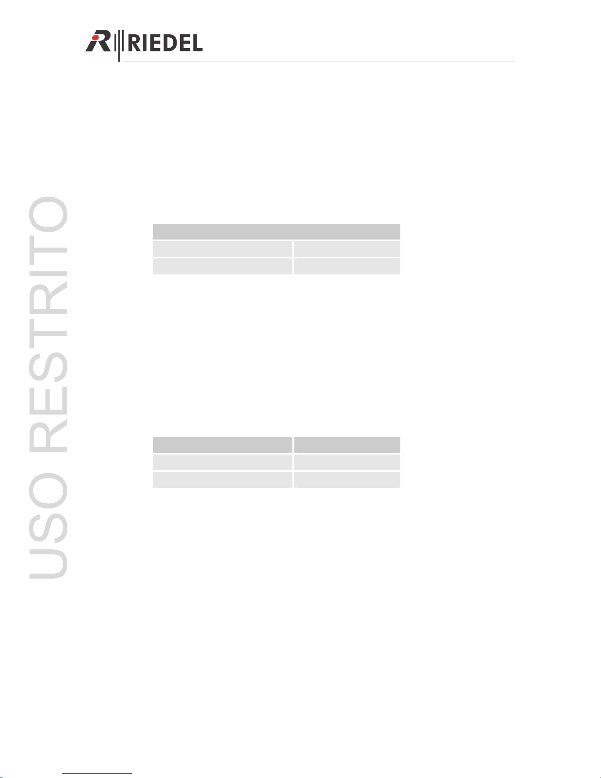
2.1 Performer CR-4 / CR-2 Master Station
The Performer master stations CR-4 (4-channel) and CR-2 (2-channel) are the ideal choice for
setting up a stand-alone digital partyline system. Depending on the set-up the integrated
power supply of the 19”/1RU device can power up to 32 beltpacks.
The color-illuminated buttons are ideal for applications in operational environments. The
remote microphone kill function allows the user to silence any open microphone on the
intercom channels. The CR-4/CR-2 features an additional program input that can be routed
individually to each of the intercom channels. Other features include individual listen volume
controls for all partylines, Call and GPI, PGM IN and a stage announce function to use the
inter-com microphone to talk over a PA system. The CR-4/CR-2 can be operated using a
headset or the integrated powerful loudspeaker and a gooseneck microphone.
2.2 Performer CD-2 Desktop Speaker / Headset Station
The Performer desktop speaker / headset station CD-2 (2-channel) provides the same
features set as the CR-2 master station except for the internal power supply. This makes the
CD-2 ideal either for operation as a desktop speaker station or – in combination with an
external power supply – as a 2-channel master station for setting up a stand-alone digital
partyline system.
The color-illuminated buttons are ideal for applications in operational environments. The
remote microphone kill function allows the user to silence any open microphone on the
intercom channels. The CD-2 features an additional program input that can be routed
individually to each of the intercom channels. Other features include individual listen volume
controls for all partylines, Call and GPI, PGM IN and a stage announce function to use the
intercom microphone to talk over a PA system.
2.3 Performer C3 Digital Beltpack
The Performer C3 is an ergonomically shaped, fully digital 2-channel beltpack that includes
all the standard features from conventional analogue party line systems including daisychaining. The beltpack uses high quality digital audio providing noise-free and hum-free
signals. Extensive DSP signal processing provides perfect side tone-nulling and excellent
intelligibility in applications with very high ambient noise levels. The C3 has three XLR
connectors, one for headset, one for signal input and one for signal loop through, which can
also be used as an additional analogue program input.
Operation is extremely convenient. Two large rotary level controls on the top of the C3 adjust
the listen volumes for CH-A and CH-B. Pushing on the A or B volume control toggles talk
on/off with momentary/latching operation to the respective channel and includes talk LED
Page 7
USO RESTRITO

PERFORMER Digital Partyline, User Manual, Version 2.30
indication. The C3 is easy to configure and also features a call send button. A bright call light
indicates an incoming call to all daisy-chained Performer devices.
2.4 Performer CW-2 Digital Wall Mount Speaker / Headset Station
The CW-2 Wall Mount Speaker / Headset station comes with a standard 4-gang outlet box
and provides an easy-to-use 2-channel digital intercom panel. The large rotary level controls
combine volume control and a talk button with momentary / latching operation. The unit can
be operated using a headset or the integrated powerful loudspeaker and a microphone. A call
signal LED, Call and S-Call function complete the feature list. The CW-2 can be powered from
the partyline or via a local power supply.
2.5 Performer C31 Split Box
The C31 Split Box splits one signal input on 3-pole female XLR onto three 3-pole male XLR
outputs. The C31 can be powered by the partyline or with an external power supply for extra
long cable runs. The use of an external power supply extends the possible length of a
partyline to a maximum of 2.5 km (1.5 miles).
2.6 Performer C44/C44plus System Interface
The C44/C44plus System Interface allows for seamless integration of digital partylines in
matrix intercom environments. The 19“/1RU unit converts four two-channel CAT5 matrix
ports to four phantom powered partylines. The partyline devices such as beltpacks are
connected to the C44/C44plus via standard 3-pole XLR cables. Up to 16 beltpacks can be
daisy-chained on each line. One C44/C44plus can power up to 38 beltpacks.
For stand-alone use the device features an integrated 24x24 port digital intercom matrix,
which can be configured via Riedel’s audio assignment software. Pre-programmed
configurations can be loaded via the DIP-switches on the front.
Full digital interfacing is provided for Artist and Performer 32 matrix systems. The AES /
analog 4-wire I/Os and GPIs are provided for interfacing to third party intercom systems. For
example, the analog input can also function as a PGM input.
The C44/C44plus provides individual short-circuit protection on each powered line. Separate
DC inputs and outputs at the rear of the unit can be used to provide redundant power.
Page 8
USO RESTRITO
PERFORMER Digital Partyline, User Manual, Version 2.30
Page 9
3 PERFORMER CR-4 / CR-2 MASTER STATION
With the Performer master stations CR-4 (4-channel) and CR-2 (2-channel) it is easy to set up
a stand-alone digital partyline system. Depending on the set-up the integrated power supply
of the 19”/1RU device can power up to 32 beltpacks.
Note: As the two Master Stations CR-4 and CR-2 are identical in their operation, this chapter
focuses on the CR-4 user elements and connectors only. Differences to the CR-2 are clearly
marked.
3.1 Getting Started
Mount the optional MIC 30 microphone to the microphone connector at the front of the unit.
For headset mode, connect an appropriate headset to one of the headset connectors.
Choose the headset microphone type with the DIP switch 5 on the back of the unit.
Now start building your partyline by connecting the next partyline device to one of the
downstream ports (CR-2 has only one downstream / upstream port) with 3-pole XLR cable.
Finally connect the Master Station with the provided power cable to the power. The system
will switch on immediately and is ready to use once the blue TALK key (channel A) goes out.
Note: In a complex system, turn on remote power supplies (such as C31 + PSU) first, before
switching on the master station.
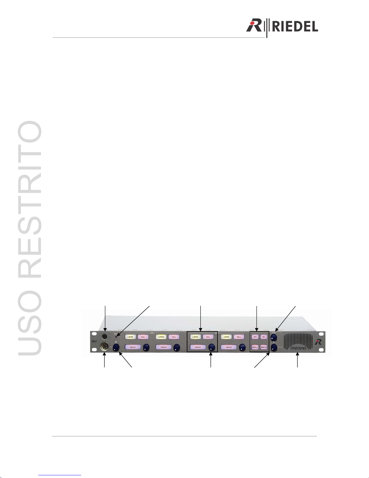
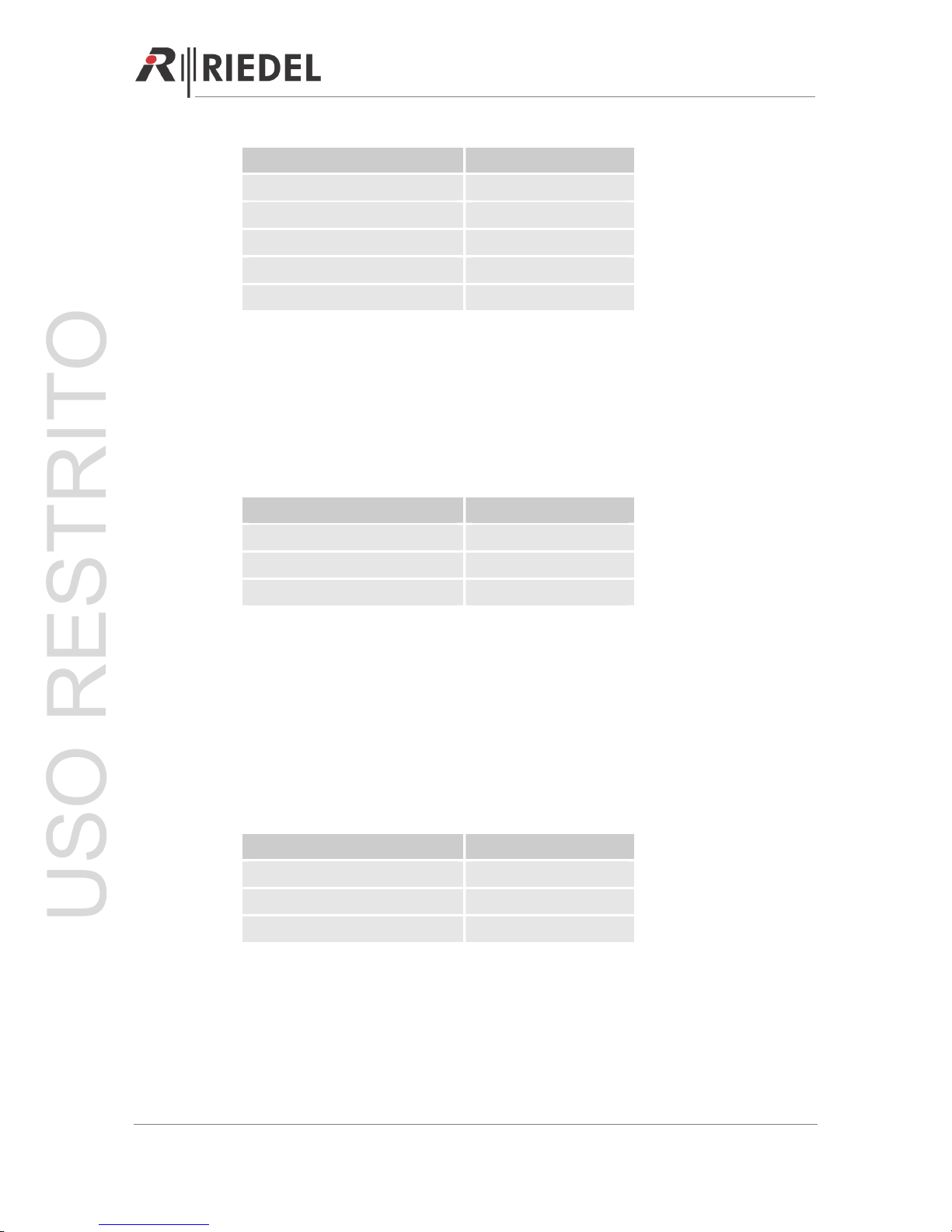
3.2 User Elements Front
The picture below shows a CR-4 master station.
Microphone
Connector
Channel Key
Block
Side tone
Ad
j
ustment
Function Key
Block
PGM
Encoder
Headset
Connector
Listen
Encoder
Headset
Encoder
Speaker
Volume
Encoder
Loudspeaker
USO RESTRITO
PERFORMER Digital Partyline, User Manual, Version 2.30
3.2.1 Microphone Connector
The microphone connector is Riedel’s standard 6.3mm microphone connector for electret
microphones, such as MIC 30 / MIC 3. Turn the microphone clockwise to attach the
microphone to the unit.
3.2.2 Headset Connector
The headset connector is 4-pole male XLR and supports headsets with electret (~ 4.5V) or
dynamic microphones, depending on the DIP switch setting.
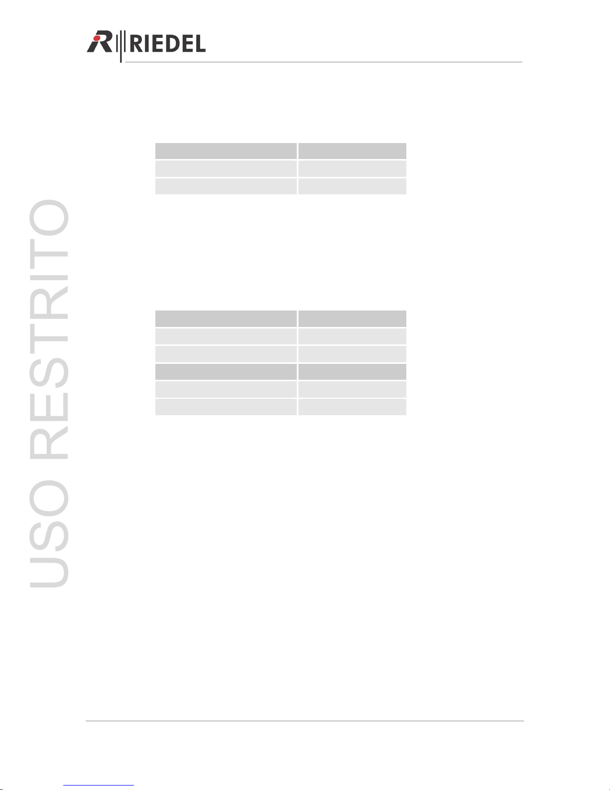
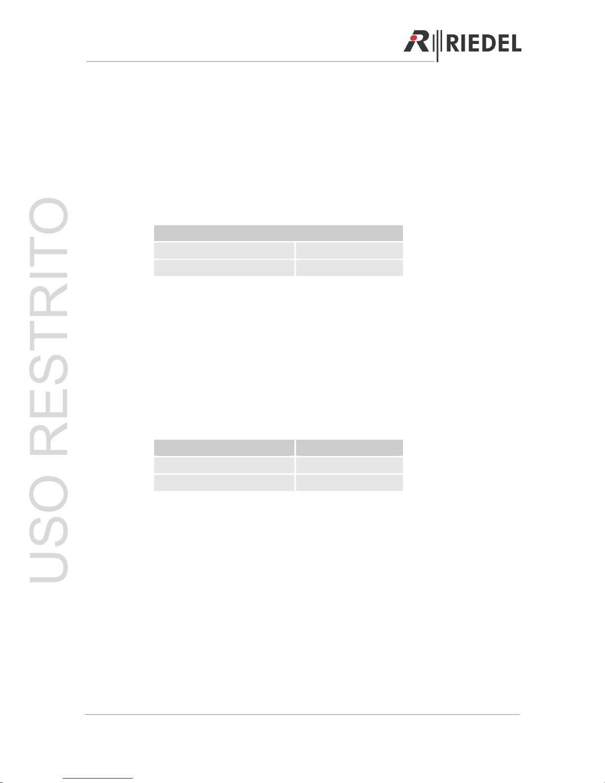
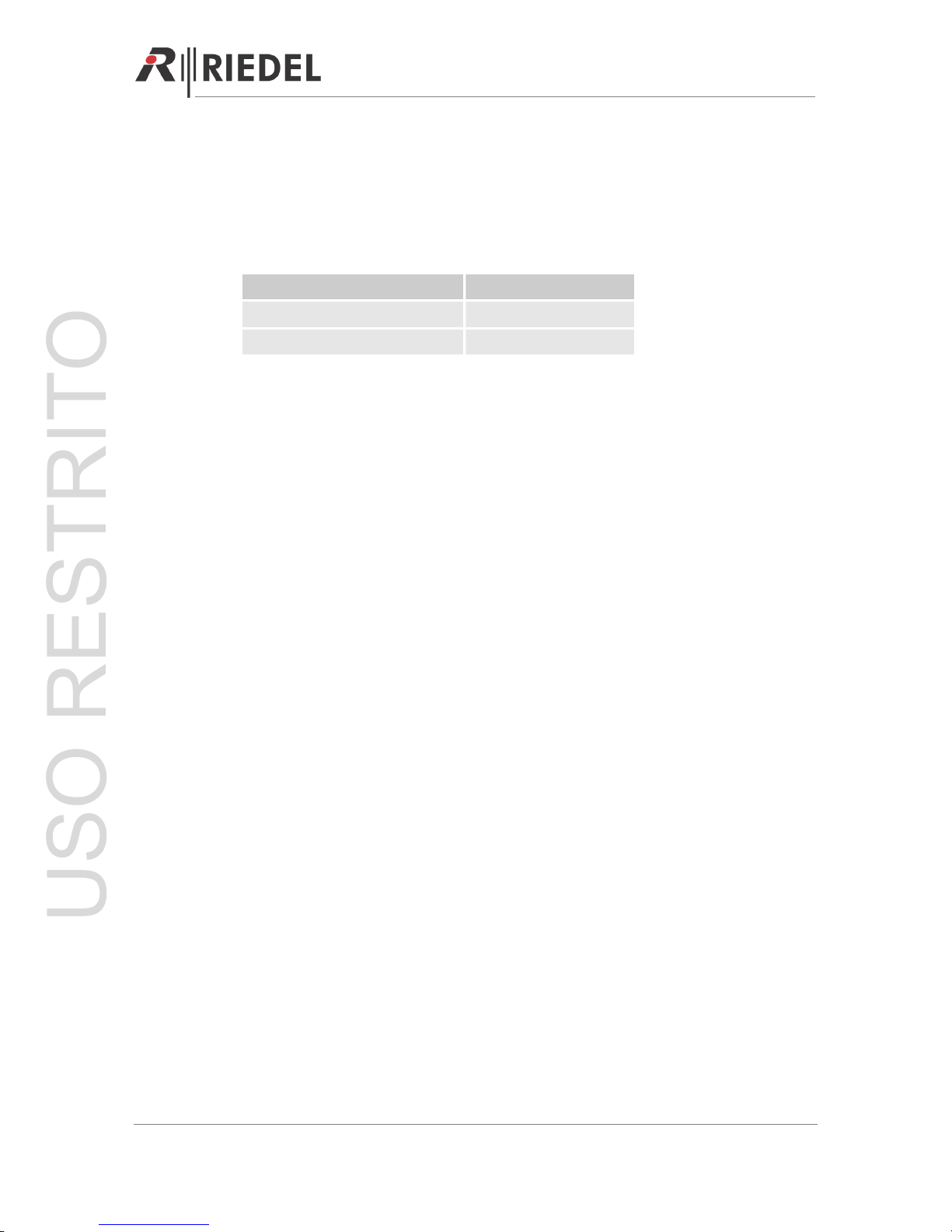
Setting
DIP SW 5 ON Electret
DIP SW 5 OFF Dynamic
3.2.3 Headset Knob (2 Functions)
Volume Control
The headset rotary encoder adjusts the volume (0-100%) of the headset speaker. Turn the
encoder clockwise to increase and counterclockwise to decrease the volume. The volume is
MUTED when the encoder is turned counterclockwise as far as it will go.
Headset Microphone ON / OFF
Pushing the rotary encoder switches between gooseneck and headset microphone.
Note: Selecting the headset microphone does not automatically mute the panel speaker!
Selection LED
Headset Microphone Green 100%, ON
Gooseneck (default mode) 0%, OFF
3.2.4 SIDE TONE Adjustment Headsets
The side tone of the headset can be adjusted by the screw trim. Turn the screw clockwise to
increase the side tone and counterclockwise to decrease it. The side tone is OFF when the
screw is turned counterclockwise as far as it will go.
Note: The side tone is only active when either the TALK or the SA (stage announcement key
(function key block) is active. The side tone is never routed to the loudspeaker.
Page 10
USO RESTRITO
PERFORMER Digital Partyline, User Manual, Version 2.30
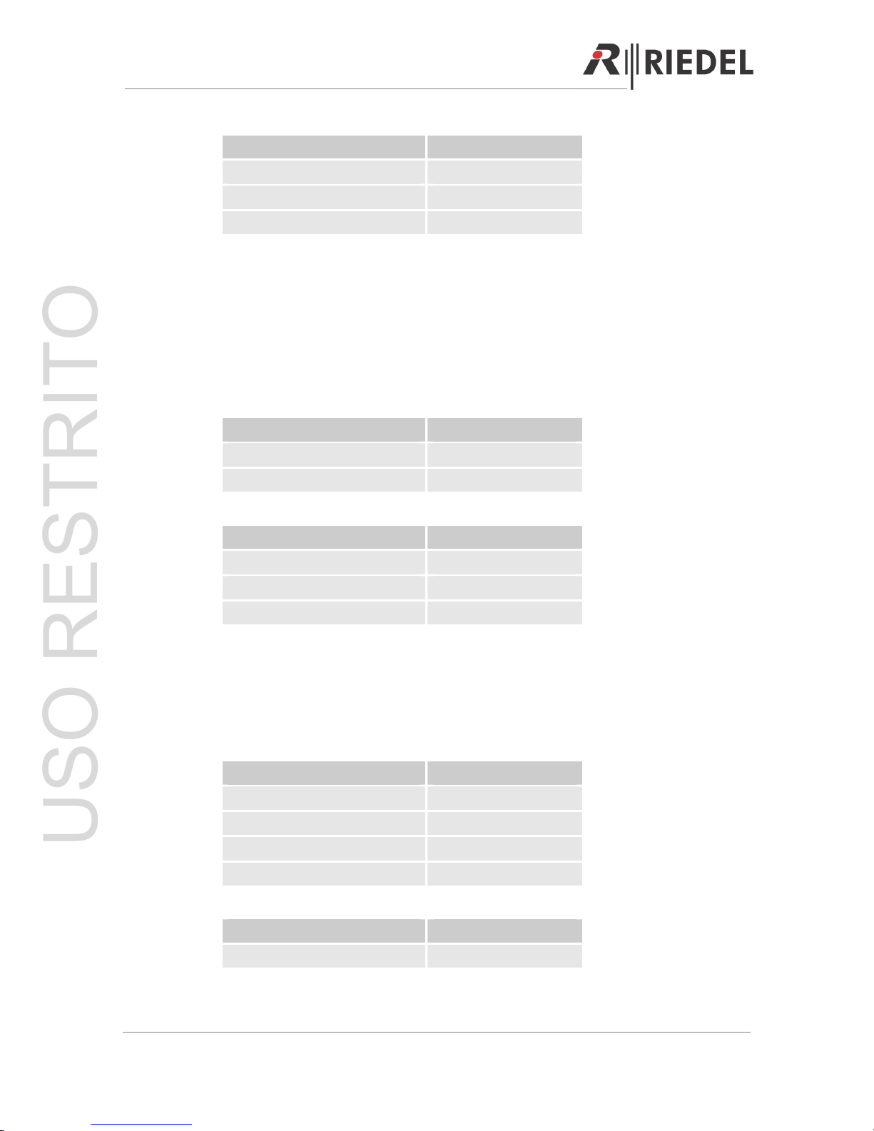
3.2.5 LISTEN (Latching)
An active LISTEN key (channel key block) enables listening to the related digital partyline
channel. If the LISTEN key is deactivated, the LISTEN function of the related partyline is
muted.
Note: The LISTEN function can also be switched ON / OFF by the LISTEN encoder.
Function LISTEN Key
LISTEN ON (default mode) Green 100%
LISTEN OFF Green 10%
3.2.6 LISTEN Knob (2 Functions)
Volume Control
The listen rotary encoder (channel key block) adjusts the LISTEN volume (0-100%) of the
related DPL channel. Turn the encoder clockwise to increase and counterclockwise to
decrease the volume. The LISTEN volume is MUTED when the encoder is turned
counterclockwise as far as it will go.
LISTEN On / Off
Pushing the rotary encoder (channel key block) switches the LISTEN ON / OFF (0 / 100%).
This function works parallel to the LISTEN key.
3.2.7 TALK A/B (Auto / Momentary)
An active TALK key (channel key block) enables talking to the related digital partyline
channel. The TALK key can be set to auto (short press=latching, long press=momentary) or
momentary using DIP switch 1 for channel A and DIP switch 2 for channel B on the back of
the unit.
Note: If the unit is in mute mode (M/MUTE key active, function key block), talking on a
channel is not possible. Formerly active or pre-selected TALK keys are indicted by a slow
flashing TALK key.
Power Failure Indication
A blue TALK key on channel A indicates a short-circuit / overload on the related partyline.
Page 11
USO RESTRITO
PERFORMER Digital Partyline, User Manual, Version 2.30
Function TALK Key
TALK ON Red 100%
TALK OFF (default mode) Red 10%
TALK ON but MUTED Red 100% slow flashing
TALK OFF and MUTED Red 10%
DPL Power Failure (TALK A) Blue 100%, Red 0%
3.2.8 CALL (2 Functions)
Light Call (Momentary)
A flashing CALL key (channel key block) indicates an incoming call on the related digital
partyline channel. Activate the LISTEN key and turn on the volume to listen to the channel.
To send a light call, press the CALL key of the DPL channel you wish to call.
Signalization CALL Key
Incoming CALL Yellow 100% flashing
Outgoing CALL Yellow 100%
Inactive CALL (default mode) Yellow 10%
Light Call (Momentary) with GPI Out Relay
A flashing CALL key (channel key block) indicates an incoming call on the related digital
partyline channel and automatically closes the corresponding GPI Out relay of the unit (Æ
prerequisite).
Pressing the CALL key sends an outgoing call and closes the GPI Out relay contacts of the
corresponding partyline channels (e.g. for an external call light indication).
Note: The GPI Out relay contact of a unit closes only if the corresponding DIP switches of the
unit are set (
Æ
prerequisite).
Signalization CALL Key
Incoming CALL Yellow 100% flashing
Outgoing CALL + GPI Out Yellow 100%
Inactive CALL (default mode) Yellow 10%
Page 12
USO RESTRITO
PERFORMER Digital Partyline, User Manual, Version 2.30
Settings
DIP SW 6 ON CH A ready for GPI Out
DIP SW 7 ON CH B ready for GPI Out
DIP SW 8 OFF GPI Out by CALL
3.2.9 GPI (Momentary)
Activating the GPI key (function key block) closes all GPI Out relay contacts (local & partyline)
associated with the active (TALK = ON) digital partyline channels.
Note: The GPI Out relay contact of a unit closes onl, if the related DIP switches of this unit are
set (
Æ
prerequisite).
Selection GPI Key
GPI active Yellow 100%
GPI inactive (default mode) Yellow 10%
Settings
DIP SW 6 ON CH A ready for GPI Out
DIP SW 7 ON CH B ready for GPI Out
DIP SW 8 ON GPI Out by GPI
3.2.10 M/Kill (Momentary)
Activating M/KILL (function key block) mutes all microphones on the active (TALK = ON)
digital partyline channels. The microphone of the local CR-4 stays active.
Note: Disable the M/KILL function with the related DIP 3 switch.
Setting M/Kill Key
M/KILL active Red 100%, 1,5 seconds
M/KILL inactive (default mode) Red 10%
M/KILL OFF – inactive Red 10%
M/KILL OFF – active Red 100%, 1,5 seconds
Setting
DIP SW 3 OFF M/KILL mode enabled
Page 13
USO RESTRITO
PERFORMER Digital Partyline, User Manual, Version 2.30
3.2.11 SA Stage Announcement (Momentary)
With an active SA (function key block) the microphone signal is routed to the SA output (local
4W) and the related GPI Out relay contact closes (Æ Pin Out D-Sub).
Selection SA Key
SA active Yellow 100%
SA inactive Yellow 10%
3.2.12 M/MUTE (Latching)
Activating M/MUTE (function key block) mutes all active TALKS of the unit.
While M/MUTE is active, TALKS can be pre-selected / deselected by pressing the related
TALK key. A pre-selcted but muted TALK key flashes slowly.
Note: The microphone of the CR-4 stays active for the stage announcement SA (local 4W).
Selection M/MUTE Key
M/MUTE active Red 100%
M/MUTE inactive Red 10%
TALK Key
“Active” TALK key - muted Red 100% slow flashing
“Inactive” TALK key - muted Red 10%
3.2.13 PGM Level Control
The PGM (program) rotary encoder adjusts the listen volume (0-100%) of the PGM input
(local 4W) of the unit. Turn the encoder clockwise to increase and counterclockwise to
decrease the volume of the program input. The PGM volume is MUTED when the encoder is
turned counterclockwise as far as it will go.
Adjust the PGM level input with the screw-adjustment of the back of the unit.
This PGM input is not routed to the partylines!
Note: Pushing the rotary encoder currently has no function (for future optional use).
Page 14
USO RESTRITO

PERFORMER Digital Partyline, User Manual, Version 2.30
Page 15
3.2.14 Speaker Volume Knob (2 Functions)
Speaker Volume
The speaker volume rotary encoder adjusts the speaker volume of the unit (0-100%). Turn
the encoder clockwise to increase the volume of the speaker and counterclockwise to
decrease the volume of the speaker. The speaker is MUTED when the encoder is turned
counterclockwise as far as it will go.
Quick Speaker Mute (Momentary)
Pushing and holding the rotary encoder temporarily mutes the audio level (0%).
Note: The speaker volume functions as the master level control. Use the individual channel
level controls of the unit to mix the audio channels. Use the speaker volume control to adjust
the volume of this mix.
USO RESTRITO

PERFORMER Digital Partyline, User Manual, Version 2.30
3.3 User Elements Rear
Power
Connector
Line 2
(CR-4 only)
SUB D
Connector
DIP Switch
Line 1
Headset
Connector
SA Out
Connector
PGM In
Connector
Line 1
Upstream
Connector
Line 1
Downstream
Connector
PGM In
Ad
j
ustment
-
-
3.3.1 Power Connector
Standard power connector for 110-220 VAC.
3.3.2 SUB D 15 Connector
The Sub D 15 connector hosts the AUX audio in- and outputs (system 4-wire) as well as all
GPI out contacts.
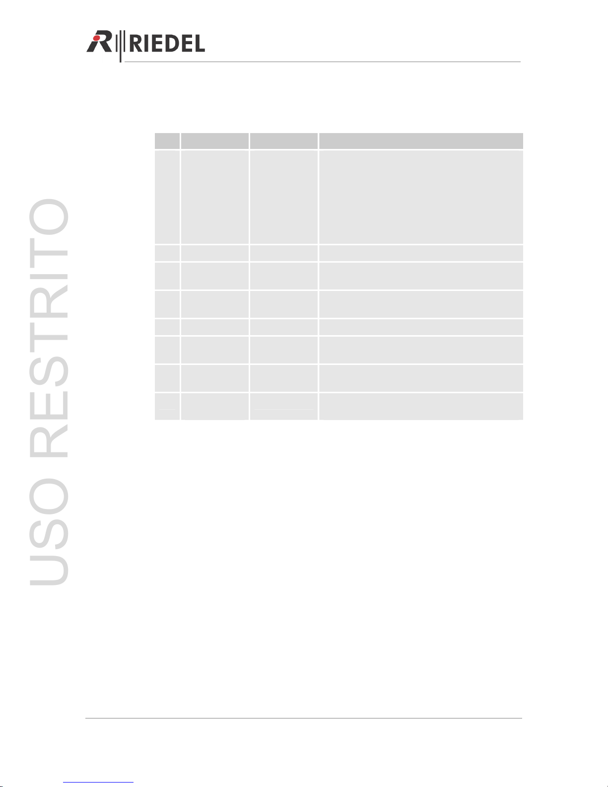
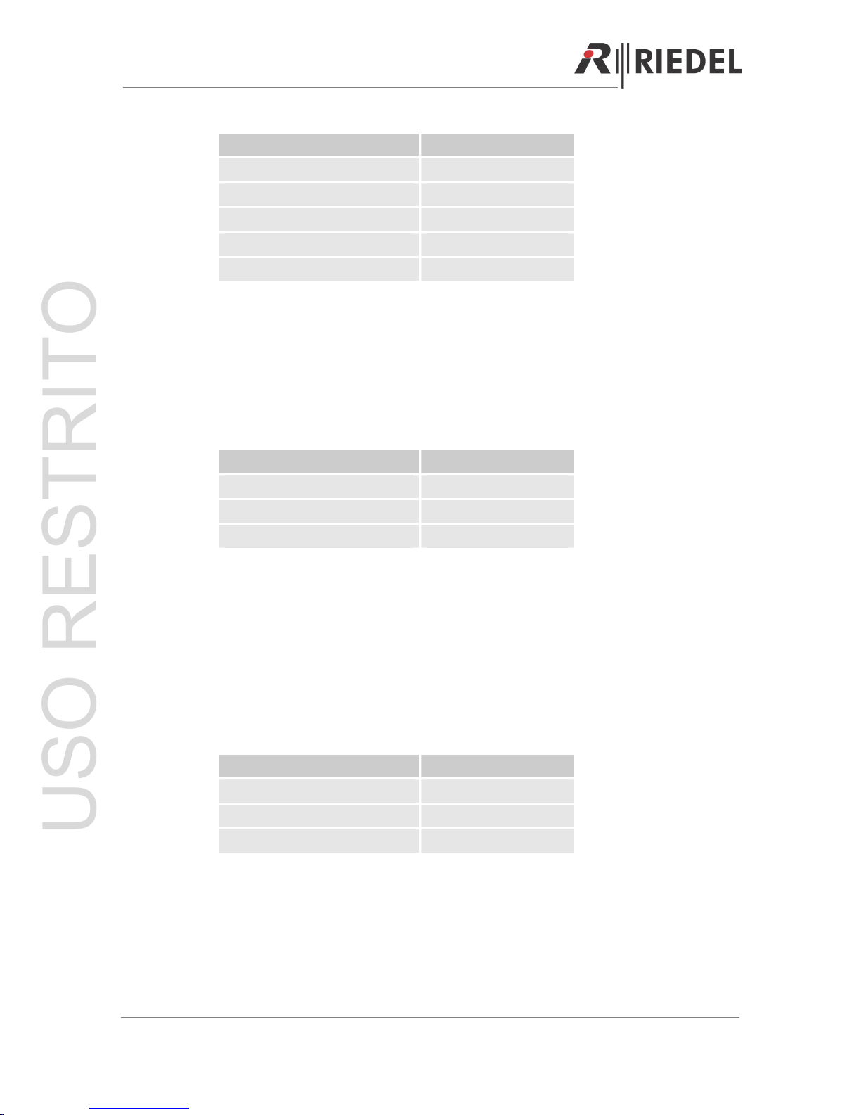
PIN PIN
1 AUX In +
2 GND 9 AUX In –
3 Aux Out + 10 AUX Out –
4 GPI Out 1 (Line 2 CH A) 11 GPI Out 1 (Line 2 CH A)
5 GPI Out 2 (Line 2 CH B) 12 GPI Out 2 (Line 2 CH B)
6 GPI Out 3 (Line 1 CH A) 13 GPI Out 3 (Line 1 CH A)
7 GPI Out 4 (Line 1 CH B) 14 GPI Out 4 (Line 1 CH B)
8 GPI Out SA 15 GPI Out SA
AUXILIARY IN / OUT
If DIP switch 6 (for CH A) and / or DIP switch 7 (for CH B) is in the ON position, the auxiliary
audio (system 4-wire) is permanently routed to the related digital partyline channel.
Page 16
USO RESTRITO

PERFORMER Digital Partyline, User Manual, Version 2.30
SA GPI out Relay
The stage announcement SA GPI out closes when the SA key is pressed.
GPI out Relay
The channel auxiliary GPI of the corresponding partyline closes when the GPI key is pressed
AND the DIP switch 6 / 7 is in position ON.
3.3.3 PGM IN Connector
3-pole female XLR connector - Symmetric analog audio input (local 4-wire) for e.g. local
program input (PGM).
Level adjustment with screw trim right next to it. Turn the screw clockwise to increase the
level and counterclockwise to decrease it.
3.3.4 SA OUT Connector
3-pole male XLR connector - Symmetric analog audio output (local 4-wire) for e.g. stage
announcement (SA)
3.3.5 Upstream Connector
3-pole female XLR connector - Digital data stream FROM the party line (female), not powered
by unit. Use this connector to connect upstream devices when the CR-4 / CR-2 is used within
a system.
3.3.6 Downstream Connector
3-pole male XLR connector - Digital data stream TO the party line (male), powered by the unit.
Use this connector to start your partyline or to daisy chain an existing partyline.
3.3.7 Headset XLR Connector
4-pole male XLR connector - Connection for an additional (second) headset
Page 17
USO RESTRITO
PERFORMER Digital Partyline, User Manual, Version 2.30
3.3.8 DIP Switch CR-4 / CR-2
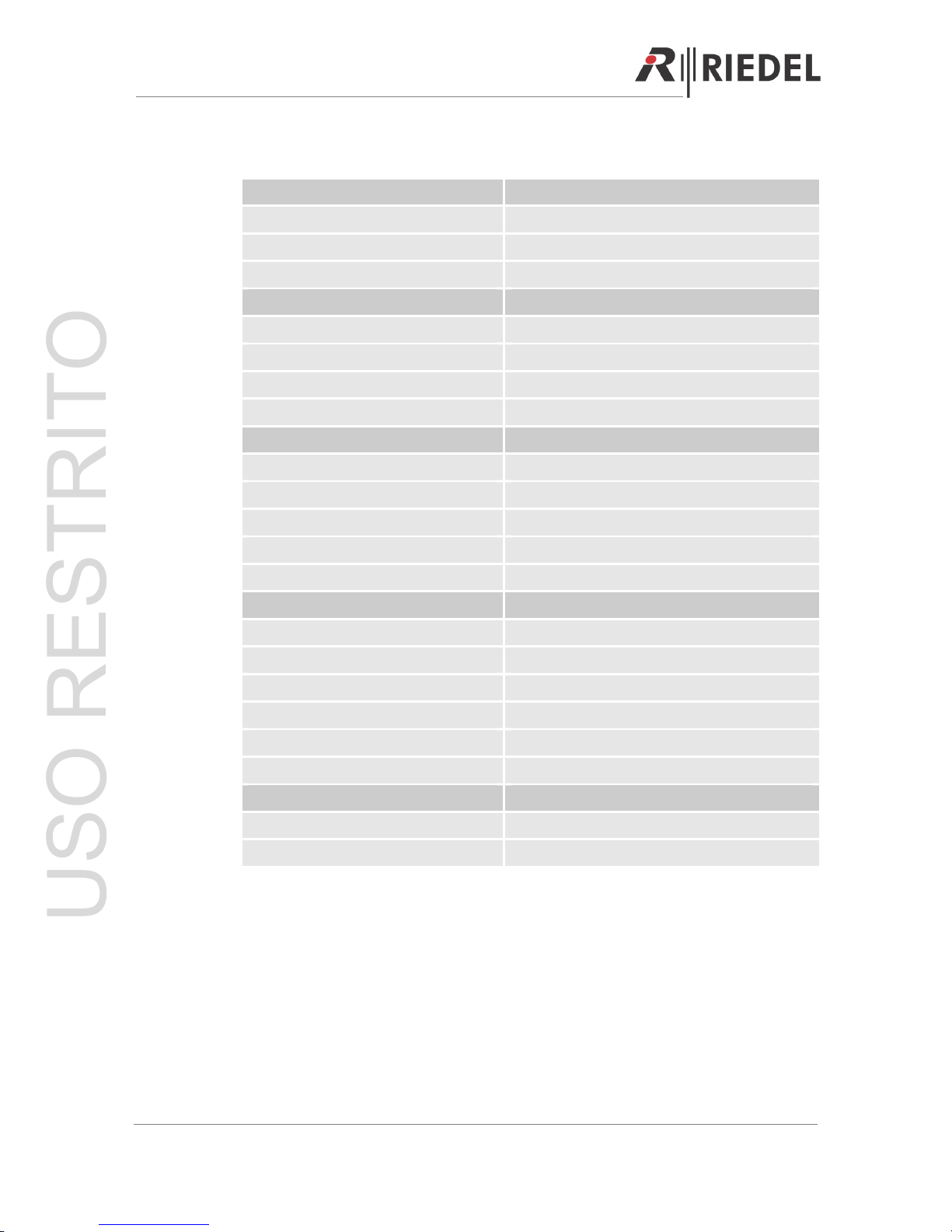
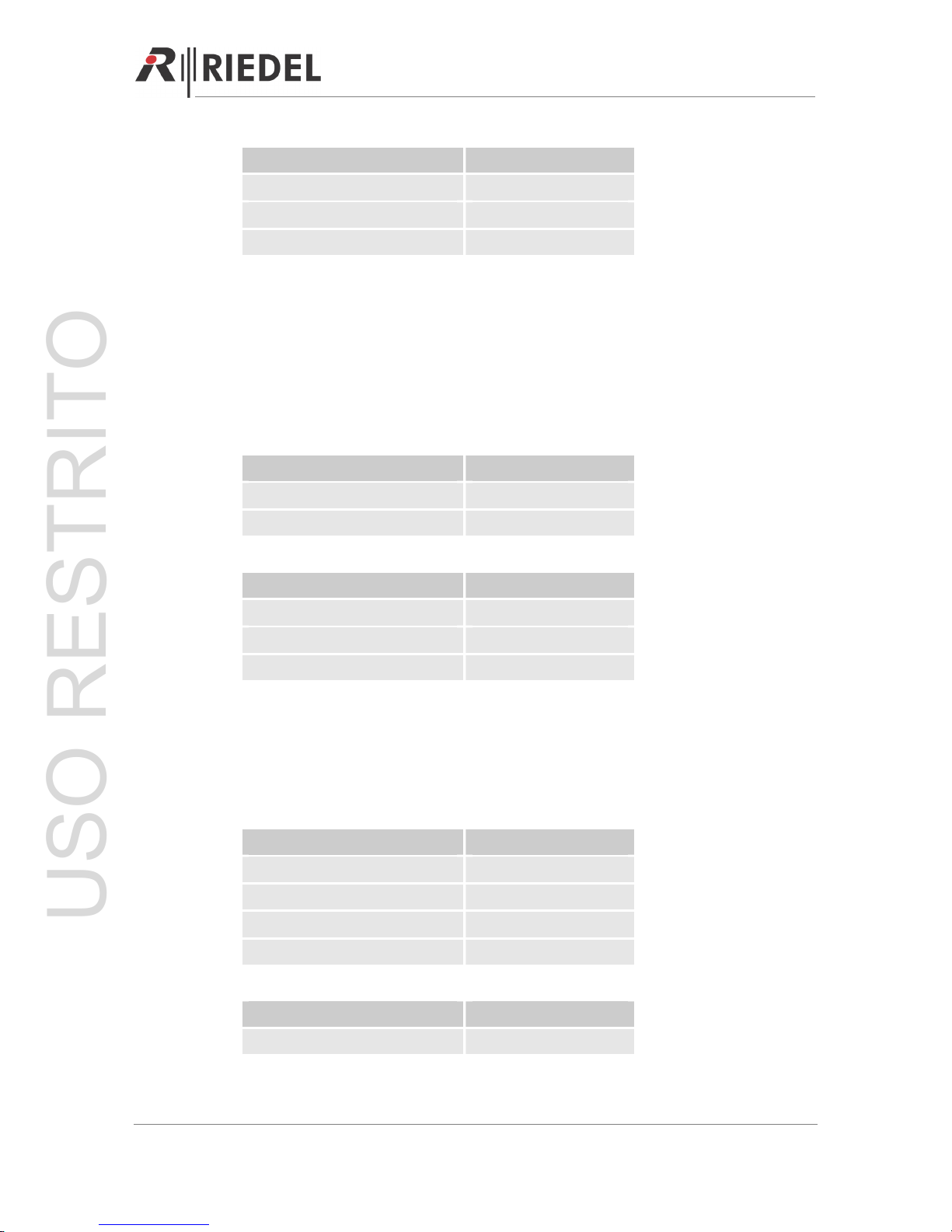
SW OFF ON
1 Auto momentary Momentary changeover / latched for TALK A.
In the ‘Off’ position, a short push on TALK A will
switch the microphone signal on channel A ON, a
second push switches it OFF again.
A longer push in OFF mode will be regarded as
momentary.
SW-1 in ON mode, TALK A is only active as long
as the button is pressed.
2 Auto momentary Momentary changeover / latched for TALK B.
3 M/Kill
enabled
M/Kill
disabled
Disables the M/Kill function of the unit
4 Talk &
listen
B listen only TALK B is disabled
5 Dynamic Electret Microphone type headset
6 AUX disabled AUX enabled AUX IN / OUT routed to digital party line channel
A
7 AUX disabled AUX enabled AUX IN / OUT routed to digital party line channel
B
8 GPI out by
CALL
GPI out by GPI The GPI out relay is triggered either by CALL or
GPI, depending on the SW setting.
Page 18
USO RESTRITO
PERFORMER Digital Partyline, User Manual, Version 2.30
3.4 Specifications
Electrical Properties Values
Audio bandwidth: 50 Hz – 20 kHz
Audio bandwidth (DPL): 50 Hz – 10 kHz
Resolution: 16 bit
Microphone Preamp:
Mic input impedance 1.6 kOhm
Dynamic mic input level -52 dBu
Electret mic input level -38 dBu
Frequency response 80 Hz to 12 kHz, ± 3 dB
Headphone Amplifier:
Load impedance 24 to 600 Ohms
Max. output level 16 Volts peak-to-peak
Max. output power 160 mW @ 200 Ohms
Frequency response 80 Hz to 12 kHz, ± 3 dB
Signal-to-noise-ratio > 82 dB (A)
Power Supply:
Output voltage +48V DC
Output current 2 A max. total
Short circuit protection per individual line
Short circuit reset time 500 ms
Power requirements 85 – 265 V AC / 47 – 63 Hz
Power consumption 120 VA (CR-4) / 85 VA (CR-2)
Dimensions:
H x W x D 44 (1 RU) x 483 x 190 mm
Mass
Page 19
USO RESTRITO

PERFORMER Digital Partyline, User Manual, Version 2.30
Page 20
4 PERFORMER CD-2 DESKTOP SPK/HS STATION
The Performer CD-2 desktop / speaker station can be easily integrated in an existing digital
partyline setup with its loop trough connectors. It does not require additional power as it is
powered over the line.
The Performer CD-2 desktop / speaker station (optional power supply required) can also be
used as an master station to set up a stand-alone digital partyline system. Depending on the
set-up the optional external power supply can power up to 32 beltpacks.
4.1 Getting Started
Mount the MIC 30 microphone (optional) to the microphone connector at the front of the unit.
For headset mode, connect an appropriate headset to one of the headset connectors.
Choose the headset microphone type with the DIP switch 5 on the back of the unit.
Now start to integrate the CD-2 in your partyline system by connecting the 3-pole XLR cable to
the up-stream port. To loop through the signal, connect the next partyline device to the
downstream port with another 3-pole XLR cable.
When the up-stream port is connected to a powered line, the system will switch on
immediately and is ready to use once the blue TALK key (channel A) goes out.
Note: To use the CD-2 as a master station or in a complex system use the optional power
supply (C31 + PSU) to power the unit or to refresh the power.
4.2 User Elements Front
Microphone Connector
Channel Key
Block
Side Tone Adjustment
Function Key
Block
PGM Encoder
Headset Connector
Headset Encoder
Speaker Volume
Encoder
Loudspeaker
USO RESTRITO
PERFORMER Digital Partyline, User Manual, Version 2.30
4.2.1 Microphone Connector
The microphone connector is Riedel’s standard 6.3mm microphone connector for electret
microphones, such as MIC 30 / MIC 3. Turn the microphone clockwise to attach the
microphone to the unit.
4.2.2 Headset Connector
The headset connector is 4-pole male XLR and supports headsets with electret (~ 4.5V) or
dynamic microphones, depending on the DIP switch setting.
Setting
DIP SW 5 ON Electret
DIP SW 5 OFF Dynamic
4.2.3 Headset Knob (2 Functions)
Volume Control
The headset rotary encoder adjusts the volume (0-100%) of the headset speaker. Turn the
encoder clockwise to increase and counterclockwise to decrease the volume. The volume is
MUTED when the encoder is turned counterclockwise as far as it will go.
Headset Microphone ON / OFF
Pushing the rotary encoder switches between gooseneck and headset microphone.
Note: Selecting the headset microphone does not automatically mute the panel speaker!
Selection LED
Headset Microphone Green 100%, ON
Gooseneck (default mode) 0%, OFF
4.2.4 SIDE TONE Adjustment Headsets
The side tone of the headset can be adjusted by the screw trim. Turn the screw clockwise to
increase the side tone and counterclockwise to decrease it. The side tone is OFF when the
screw is turned counterclockwise as far as it will go.
Note: The side tone is only active when either the TALK or the SA (stage announcement key
(function key block) is active. The side tone is never routed to the loudspeaker.
Page 21
USO RESTRITO
PERFORMER Digital Partyline, User Manual, Version 2.30
4.2.5 LISTEN (Latching)
An active LISTEN key (channel key block) enables listening to the related digital partyline
channel. If the LISTEN key is deactivated, the LISTEN function of the related partyline is
muted.
Note: The LISTEN function can also be switched ON / OFF by the LISTEN encoder.
Function LISTEN Key
LISTEN ON (default mode) Green 100%
LISTEN OFF Green 10%
4.2.6 LISTEN Knob (2 Functions)
Volume Control
The listen rotary encoder (channel key block) adjusts the LISTEN volume (0-100%) of the
related DPL channel. Turn the encoder clockwise to increase and counterclockwise to
decrease the volume. The LISTEN volume is MUTED when the encoder is turned
counterclockwise as far as it will go.
LISTEN On / Off
Pushing the rotary encoder (channel key block) switches the LISTEN ON / OFF (0 / 100%).
This function works parallel to the LISTEN key.
4.2.7 TALK A/B (Auto / Momentary)
An active TALK key (channel key block) enables talking to the related digital partyline
channel. The TALK key can be set to auto (short press=latching, long press=momentary) or
momentary using DIP switch 1 for channel A and DIP switch 2 for channel B on the back of
the unit.
Note: If the unit is in mute mode (M/MUTE key active, function key block), talking on a
channel is not possible. Formerly active or pre-selected TALK keys are indicted by a slow
flashing TALK key.
Power Failure Indication
A blue TALK key on channel A indicates a short-circuit / overload on the related partyline.
Page 22
USO RESTRITO
PERFORMER Digital Partyline, User Manual, Version 2.30
Function TALK Key
TALK ON Red 100%
TALK OFF (default mode) Red 10%
TALK ON but MUTED Red 100% slow flashing
TALK OFF and MUTED Red 10%
DPL Power Failure (TALK A) Blue 100%, Red 0%
4.2.8 CALL (2 Functions)
Light Call (Momentary)
A flashing CALL key (channel key block) indicates an incoming call on the related digital
partyline channel. Activate the LISTEN key and turn on the volume to listen to the channel.
To send a light call, press the CALL key of the DPL channel you wish to call.
Signalization CALL Key
Incoming CALL Yellow 100% flashing
Outgoing CALL Yellow 100%
Inactive CALL (default mode) Yellow 10%
Light Call (Momentary) with GPI Out Relay
A flashing CALL key (channel key block) indicates an incoming call on the related digital
partyline channel and automatically closes the corresponding GPI Out relay of the unit (Æ
prerequisite).
Pressing the CALL key sends an outgoing call and closes the GPI Out relay contacts of the
corresponding partyline channels (e.g. for an external call light indication).
Note: The GPI Out relay contact of a unit closes only if the corresponding DIP switches of the
unit are set (
Æ
prerequisite).
Signalization CALL Key
Incoming CALL Yellow 100% flashing
Outgoing CALL + GPI Out Yellow 100%
Inactive CALL (default mode) Yellow 10%
Page 23
USO RESTRITO
PERFORMER Digital Partyline, User Manual, Version 2.30
Settings
DIP SW 6 ON CH A ready for GPI Out
DIP SW 7 ON CH B ready for GPI Out
DIP SW 8 OFF GPI Out by CALL
4.2.9 GPI (Momentary)
Activating the GPI key (function key block) closes all GPI Out relay contacts (local & partyline)
associated with the active (TALK = ON) digital partyline channels.
Note: The GPI Out relay contact of a unit closes onl, if the related DIP switches of this unit are
set (
Æ
prerequisite).
Selection GPI Key
GPI active Yellow 100%
GPI inactive (default mode) Yellow 10%
Settings
DIP SW 6 ON CH A ready for GPI Out
DIP SW 7 ON CH B ready for GPI Out
DIP SW 8 ON GPI Out by GPI
4.2.10 M/Kill (Momentary)
Activating M/KILL (function key block) mutes all microphones on the active (TALK = ON)
digital partyline channels. The microphone of the local CD-2 stays active.
Note: Disable the M/KILL function with the related DIP 3 switch.
Setting M/Kill Key
M/KILL active Red 100%, 1,5 seconds
M/KILL inactive (default mode) Red 10%
M/KILL OFF – inactive Red 10%
M/KILL OFF – active Red 100%, 1,5 seconds
Setting
DIP SW 3 OFF M/KILL mode enabled
Page 24
USO RESTRITO
 Loading...