

Riedel CCP1116 Quick Manual
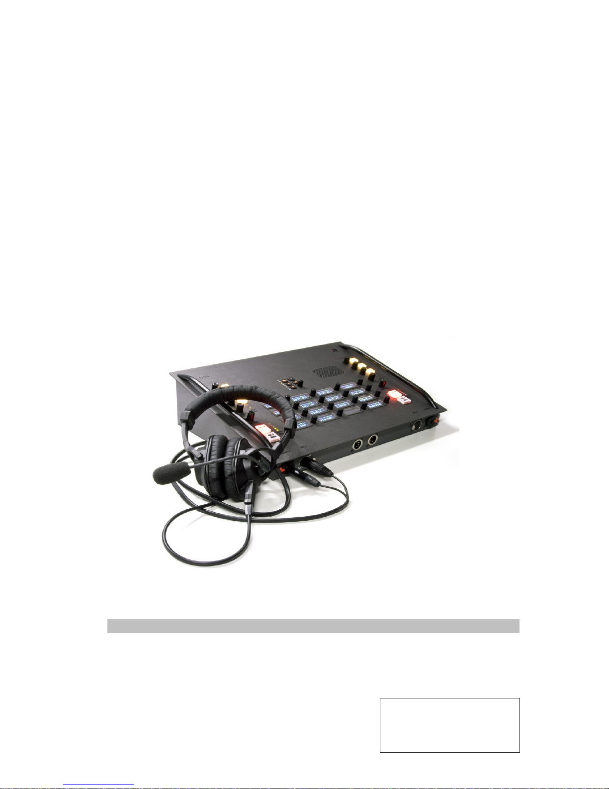
CCP1116
Quick Guide
Commentary Panel
Document Reference 1.2
S.Franke
01/2013

© 2013 Riedel Communications GmbH & Co KG. Alle Rechte vorbehalten.
Dieses Handbuch ist urheberrechtlich geschützt. Das Kopieren, Vervielfältigen, Übersetzen oder Umsetzen in irgendein elektronisches Medium oder maschinell lesbare Form im
Ganzen oder in Teilen ohne vorherige schriftliche Genehmigung von Riedel ist nicht gestattet. Riedel übernimmt keine Gewähr für die Richtigkeit des Inhalts dieses Handbuchs.
Die Rechte an anderen in diesem Handbuch erwähnten Marken- und Produktnamen liegen bei ihren Inhabern und werden hiermit anerkannt.
© 2013 Riedel Communications GmbH & Co KG. All rights reserved.
Under the copyright laws, this manual may not be copied, in whole or in part, without the written consent of Riedel. Every effort has been made to ensure that the information in
this manual is accurate. Riedel is not responsible for printing or clerical errors. All trademarks are the property of their respective owners.

CCP-1116 Commentary Control Panel – Quick Guide 1.2
TABLE OF CONTENT
1 CONTROL ELEMENTS - DESCRIPTION .......................................................................................................................... 4
2 CONNECTORS .................................................................................................................................................................. 5
2.1 Connectors front side .............................................................................................................................................................. 5
2.2 Connectors rear side ................................................................................................................................................................ 6
3 REAR SIDE - DIP SWITCHES .......................................................................................................................................... 7
4 AUDIO BLOCK DIAGRAM ................................................................................................................................................ 8
5 DIRECTOR CONFIGURATION OF A CCP-1116 ............................................................................................................. 9
5.1 Key assignment Commentator A/B ................................................................................................................................... 10
5.2 GPIO functions ....................................................................................................................................................................... 12
5.3 Commentary Audiopatch settings ...................................................................................................................................... 13
6 PANEL TEST / CONFIG MODE ..................................................................................................................................... 15
6.1 Info .......................................................................................................................................................................................... 15
6.2 Key Test .................................................................................................................................................................................. 15
6.3 Config ...................................................................................................................................................................................... 16
6.3.1 Config: Text Color............................................................................................................................................................... 16
6.3.2 Pan Type ............................................................................................................................................................................. 17
6.4 Demo Mode............................................................................................................................................................................ 17
7 SPECIFICATIONS .......................................................................................................................................................... 18
8 SERVICE ......................................................................................................................................................................... 19
9 NOTES ............................................................................................................................................................................ 20
CCP-1116 Commentary Control Panel – Quick Guide 1.2
Page 4
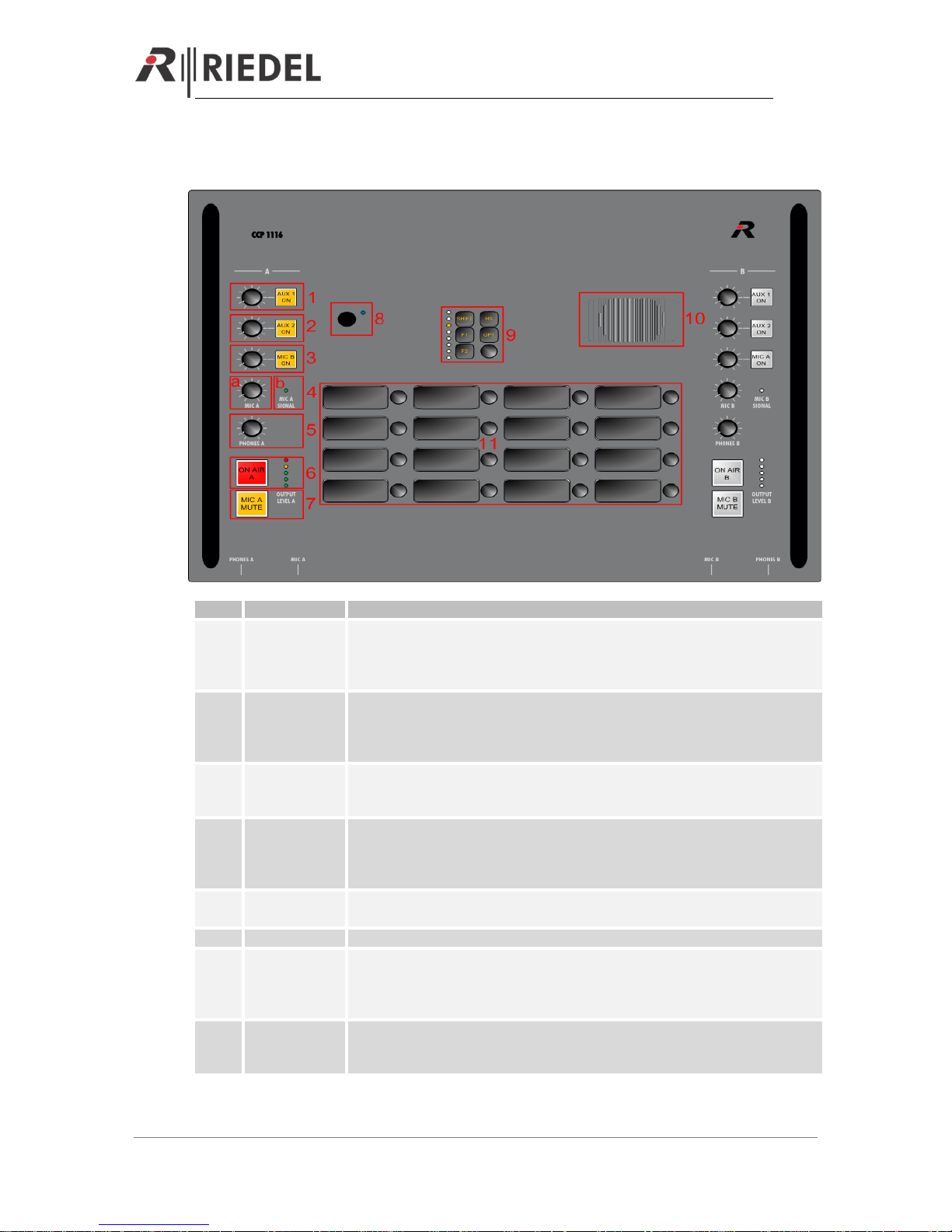
1 CONTROL ELEMENTS - DESCRIPTION
Nr.
Function
Description
1
AUX 1 ON
Activating the button: Mixes analog input „AUX 1“ from the rear side to the
Headphones (depending of the dip-settings on the rear side to the left-, right- or
both ears). The button will light up in yellow. With the Levelmeter you can adjust
the listen level.
2
AUX 2 ON
Activating the button: Mixes analog input „AUX 2“ from the rear side to the
Headphones (depending of the dip-settings on the rear side to the left-, right- or
both ears). The button will light up in yellow. With the Levelmeter you can adjust
the listen level.
3
MIC B ON
Activating the button: Mixes the MIC B from 2nd commentator to the Headphones
(depending of the dip-settings on the rear side to the left-, right- or both ears). The
button will light up in yellow. With the Levelmeter you can adjust the listen level.
4a
MIC A
Sidetone: Mixes the “MIC A” signal to the Headphones A (depending of the dipsettings on the rear side to the left-, right- or both ears). With the Dip switch
“Always” you can choose to activate the Sidetone always or only when ON AIR is
pressed
4b
MIC A Signal
LED
Indicates green, as soon a signal from MIC A is coming into the CCP-1116. LEDcolor changes to orange, when the signal is clipping
5
PHONES A
Adjust the outgoing volume to Phones A
6
ON AIR A
(Latching)
Activates the “ON AIR” function. When activated, the Button light up red. The “MIC
A” is sent to the analog outputs “AIR A OUT” and “AIR A+B OUT”. Also GPI IN 1 is
internally activated and can be used within the Artist configuration. The Level
meter is showing the ON AIR Mic level with green and orange LEDs
7
MIC A MUTE
(Momentary)
Mute the “MIC A” input. When activated the button light up yellow. If “ON AIR” is
activated, also this button changes color to yellow. The “MIC MUTE” buttons can
also be activated via GPO 1 (A) and 2 (B) within the Artist configuration
CCP-1116 Commentary Control Panel – Quick Guide 1.2
Page 5
8
Intercom Mic
Connector for standard Artist microphones. Normally not used for commentary
mode, only when the CCP-1116 is used as ordinary Intercom panel.
9
Function keys
Standard Artist panel function keys (Shift, HS, OPT, F1, F2) + Master Volume.
ATTENTION: The Master Volume is not influencing the volume of Phones A or B
10
Speaker
Panel speaker. Normally not used for commentary mode, only when the CCP1116 is used as ordinary Intercom panel.
11
Intercom OLED
keys
Standard keys, to be configured within the Artist configuration
1-7 is identically also for Commentator B
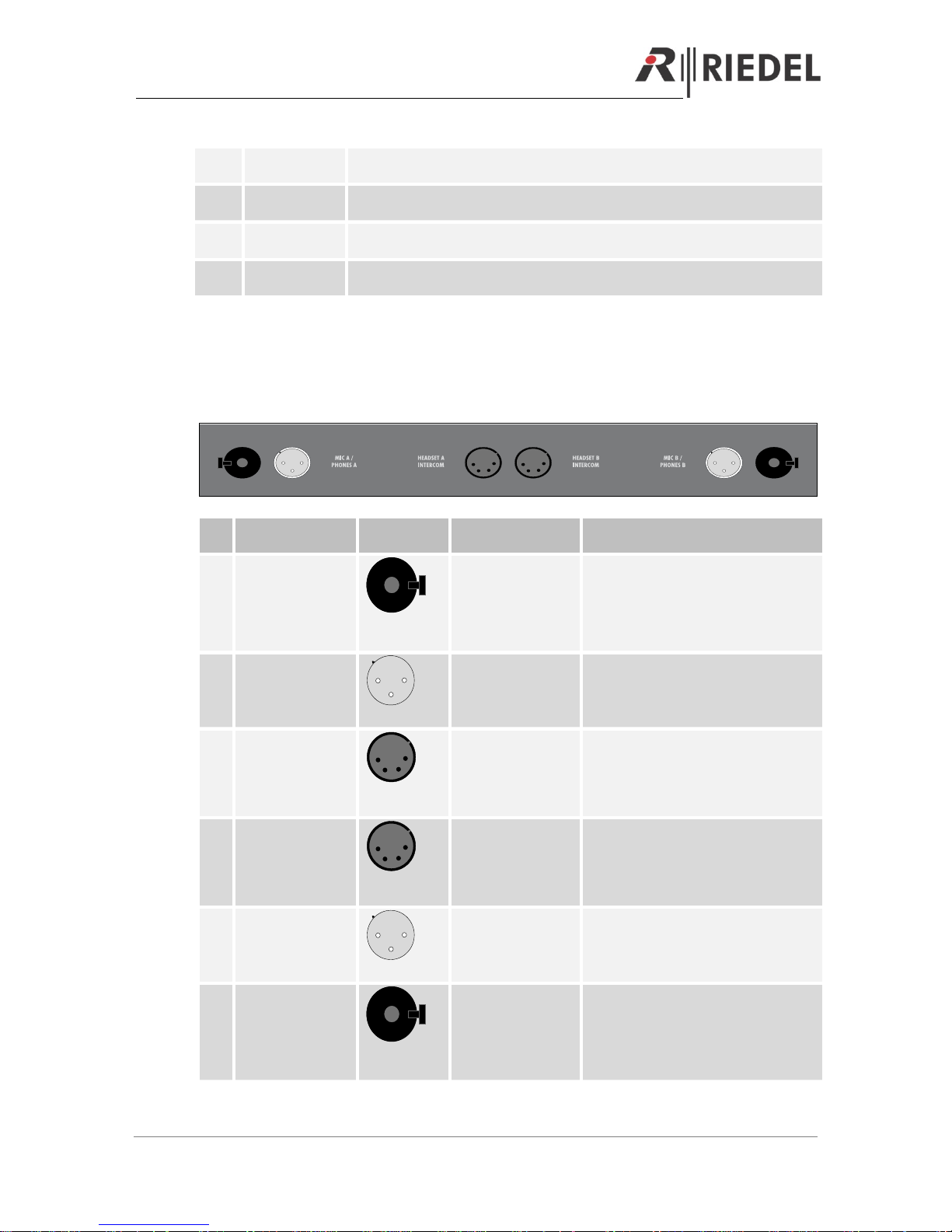
2 CONNECTORS
2.1 Connectors front side
1 2 3 4 5 6
Nr.
Function
Connector
Type
Artist Director
Pin out
1
PHONES A
6,35mm
Stereo Jack
Audio Patch:
Audio OUT A
Tip: Left
Ring : Right
Sleeve: GND
2
MIC A
1
2
3
XLR3 female
Audio Patch:
Audio IN A
Pin 1 : Shield
Pin 2 : Signal + (hot)
Pin 3 : Signal – (cold)
3
HEADSET A
INTERCOM
(only for pure
Intercom use)
1
2 3
4
XLR4 male
Audio Patch:
Headset A
Pin 1: Shield (Mic -)
Pin 2: MIC + (+4V - switchable within
Director)
Pin 3: Phones –
Pin 4: Phones +
4
HEADSET B
INTERCOM
(only for pure
Intercom use)
1
2 3
4
XLR4 male
Audio Patch:
Headset B
Pin 1: Shield (Mic -)
Pin 2: MIC + (+4V - switchable within
Director)
Pin 3: Phones –
Pin 4: Phones +
5
MIC B
1
2
3
XLR3 female
Audio Patch:
Audio IN B
Pin 1 : Shield
Pin 2 : Signal + (hot)
Pin 3 : Signal – (cold)
6
PHONES B
6,35mm
Stereo Jack
Audio Patch:
Audio OUT B
Tip: Left
Ring : Right
Sleeve: GND
CCP-1116 Commentary Control Panel – Quick Guide 1.2
Page 6
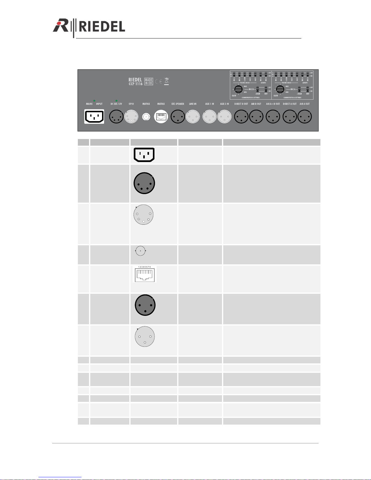
2.2 Connectors rear side
1
2
3
4
5
1
2
3
4
5 6
7
8
9
10 11
12
13
14
Nr.
Function
Connector Type
Artist
Pin out
1
Main Input
90-265V, 47-63Hz
2
DC EXT. 12V
1
2 3
4
XLR4 male
Pin 1: GND
Pin 2: n.c.
Pin 3: n.c.
Pin 4: +10 …+14VDC (3A)
3
GPIO
1
2
3
4
5
XLR5 female
Panel GPI IN 3
Panel GPI Out 3
Pin 1: OUT - ( > Director: GPI Out 3)
Pin 2: OUT + ( > Director: GPI Out 3)
Pin 3: IN - ( > Director: GPI IN 3)
Pin 4: IN + ( > Director: GPI IN 3)
Pin 5: +5V (250mA)
Shield: Ground
4
MATRIX (BNC)
BNC
Pin: Tx/RX Data +
Shield: Tx/Rx Data -
5
MATRIX (CAT5)
CAT5
Pin 1: TxD +
Pin 2: TxD –
Pin 3: RxD +
Pin 6: RxD -
6
Ext. Speaker
1 2
3
XLR3 male
Audio Patch:
Ext. OUT
Tip: Left
Ring : Right
Sleeve: GND
7
LINE IN
1
2
3
XLR3 female
Audio Patch:
External MIC
(only available in
Speaker Mode)
Pin 1 : Shield
Pin 2 : Signal + (hot)
Pin 3 : Signal – (cold)
8
AUX 1 IN
XLR3 female
n.a.
See 7
9
AUX 2 IN
XLR3 female
n.a.
See 7
10
DIRECT B OUT
(permanent)
XLR3 male
n.a.
See 6
11
AIR B OUT
XLR3 male
n.a.
See 6
12
AIR A+B OUT
XLR3 male
n.a.
See 6
13
DIRECT A OUT
(permanent)
XLR3 male
n.a.
See 6
14
AIR A OUT
XLR3 male
n.a.
See 6
CCP-1116 Commentary Control Panel – Quick Guide 1.2
Page 7
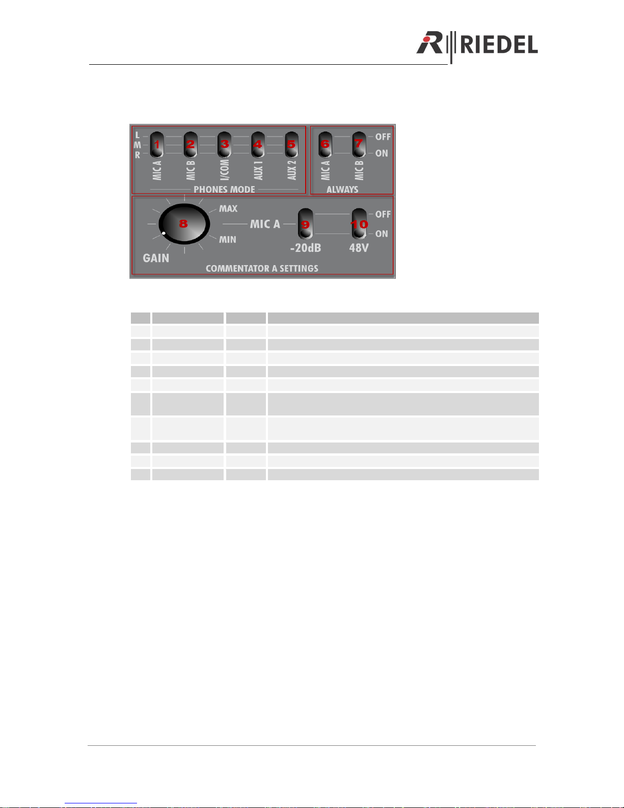
3 REAR SIDE - DIP SWITCHES
Example for Commentator A. Identical functionality for Commentator B
Nr.
Function Group
Function
Description
1
PHONES MODE
MIC A
Routes MIC A signal (Sidetone) to left-(L), right- (R), or both ears (M)
2
PHONES MODE
MIC B
Routes MIC B signal to left-(L), right- (R), or both ears (M)
3
PHONES MODE
I/COM
Routes Intercom signal to left-(L), right- (R), or both ears (M)
4
PHONES MODE
AUX 1
Routes AUX 1 signal to left-(L), right- (R), or both ears (M)
5
PHONES MODE
AUX 2
Routes AUX 2 signal to left-(L), right- (R), or both ears (M)
6
ALWAYS
MIC A
Sidetone MIC A: Always routed to the phones A, or only when “ON AIR
A” is pressed
7
ALWAYS
MIC B
MIC B signal always routed to the phones or only when “ON AIR B” is
pressed. Only works when “MIC B ON” is activated.
8
MIC Settings
GAIN
Adjust Mic Input gain
9
MIC Settings
-20dB
Switch between Dynamic- (OFF) and Electret Microphone (-20dB ON)
10
MIC Settings
48V
Switch 48V Phantom power ON/OFF
 Loading...