

SeeSnake®FlatPack and Color FlatPack
Record Serial Number below and retain product serial number which is located on nameplate.
Serial No.
Kollmann
SeeSnake
®
FlatPack
and Color FlatPack
SeeSnake®Diagnostic Equipment
99 Washington Street
Melrose, MA 02176
Phone 781-665-1400
Toll Free 1-800-517-8431
Visit us at www.TestEquipmentDepot.com
Test Equipment Depot - 800.517.8431 - 99 Washington Street Melrose, MA 02176
FAX 781.665.0780 - TestEquipmentDepot.com

Table of Contents
Recording Form for Machine Model and Serial Number ...........................................................................................1
General Safety Information
Work Area Safety........................................................................................................................................................2
Electrical Safety...........................................................................................................................................................2
Battery Precautions..................................................................................................................................................2
Personal Safety...........................................................................................................................................................2
Tool Use and Care......................................................................................................................................................3
Service ........................................................................................................................................................................3
Specific Safety Information
Equipment Safety........................................................................................................................................................4
Description, Specifications and Standard Equipment
Description ..................................................................................................................................................................4
System Components...................................................................................................................................................4
Camera Head...........................................................................................................................................................4
Drum.........................................................................................................................................................................5
Monitor Pack Camera Control Unit (CCU) ...............................................................................................................5
Specifications..............................................................................................................................................................7
Standard Equipment....................................................................................................................................................7
Set Up and Operation
Equipment Set Up.......................................................................................................................................................7
Connections .............................................................................................................................................................7
Operation..................................................................................................................................................................8
Video Recording.......................................................................................................................................................8
At the Job Site.............................................................................................................................................................9
Transportation & Storage ...........................................................................................................................................10
Centering Guides.........................................................................................................................................................11
Installing the SeeSnake®Star-Type Centering Guides..............................................................................................11
Installing Star-Type Centering Guides ...................................................................................................................11
Removing Star-Type Centering Guides .................................................................................................................12
Installing the SeeSnake®Compact, and FlatPack Ball-Type Centering Guides........................................................12
Maintenance and Cleaning
Preventative Maintenance.........................................................................................................................................13
Camera Head.........................................................................................................................................................13
Spring Assembly ....................................................................................................................................................13
Push Cable and Drum............................................................................................................................................13
Monitor Pack ..........................................................................................................................................................13
Locating Faulty Components.....................................................................................................................................13
Service and Repair ......................................................................................................................................................14
Troubleshooting ..........................................................................................................................................................15
Icon Legend .................................................................................................................................................................15
Lifetime Warranty..........................................................................................................................................Back Cover
Ridge Tool Companyii
SeeSnake®FlatPack and Color FlatPack
Kollmann

SeeSnake®FlatPack and Color FlatPack
Kollmann
Ridge Tool Company2
General Safety Information
CAUTION! Read and understand all instructions. Failure
to follow all instructions listed below may
result in electric shock, fire, and/or serious
personal injury.
SAVE THESE INSTRUCTIONS!
Work Area Safety
• Keep your work area clean and well lit. Cluttered
benches and dark areas may cause accidents.
• Do not operate electrical devices or power tools in
explosive atmospheres, such as in the presence of
flammable liquids, gases, or heavy dust. Electrical
devices or power tools create sparks which may ignite
the dust or fumes.
• Keep bystanders, children, and visitors away
while operating tool. Distractions can cause you
to lose control.
• Do not let visitors contact the tool or extension
cord. Such preventative measures reduce the risk
of injury.
Electrical Safety
• Avoid body contact with grounded surfaces such
as pipes, radiators, ranges and refrigerators. There
is an increased risk of electrical shock if your body is
grounded.
• Tool is only splash resistant when the Monitor
Shield is in place. Water entering a power tool will increase the risk of electrical shock. Keep battery out of
direct contact with water. Protect AC adapter from
damp or wet conditions.
• Do not abuse cord. Never use the cord to carry the
tool or pull the plug from an outlet. Keep cord
away from heat, oil, sharp edges, or moving parts.
Replace damaged cords immediately. Damaged
cords increase the risk of electrical shock.
• When operating a power tool outside, use an out-
door extension cord marked “W-A” or “W
”
. These
cords are rated for outdoor use and reduce the risk of
electrical shock.
• Connect the tool to an AC power supply that
matches the name plate specification (120 or 240
Volts). Incorrect voltage supply can cause electrical
shock or burns.
• Use proper extension cords. (See chart.) Insufficient
conductor size will cause excessive voltage drop and
loss of power.
• Reduce the risk of electrical shock! Keep all elec-
trical connections dry and off the ground. Do not
touch plug with wet hands.
Battery Precautions
• Use only the size and type of battery specified.
• Be sure to install the battery with the correct po-
larity as indicated in the battery compartment.
• Recharge batteries with charging units specified by
the battery manufacturer. Using an improper charger
can overheat and rupture the battery.
• Properly dispose of the battery. Exposure to high
temperatures can cause the battery to explode,
so do not dispose of in a fire. Some countries have
regulations concerning battery disposal. Please follow all applicable regulations.
Personal Safety
• Stay alert, watch what you are doing and use common sense when operating a power tool. Do not
use tool while tired or under the influence of drugs,
alcohol, or medications. A moment of inattention
while operating power tools may result in serious personal injury.
• Dress properly. Do not wear loose clothing or jew-
elry. Contain long hair. Keep your hair, clothing, and
gloves away from moving parts. Loose clothes, jew-
elry, or long hair can be caught in moving parts.
• Gloves should always be worn for health and safety
reasons. Sewer lines are unsanitary and may contain
harmful bacteria and viruses.
• Do not overreach. Keep proper footing and bal-
ance at all times. Proper footing and balance enables
better control of the tool in unexpected situations.
• Use safety equipment. Always wear eye protection.
Dust mask, non-skid safety shoes, hard hat, or hearing
protection must be used for appropriate conditions.
• Use proper accessories. Do not place this product
on any unstable cart or surface. The product may fall
causing serious injury to a child or adult or serious
damage to the product.
Minimum Wire Gauge for Extension Cord
Nameplate Total Length (in feet/meters),
Amps Gauge (in AWG/mm2)
0 - 25/0 - 8 26 - 50/8 - 15 51 - 100/15 - 30
0 – 6
18 AWG/.75mm216 AWG/1.00mm216 AWG/1.00mm
2
6 – 10
18 AWG/1.00mm216 AWG/1.00mm214 AWG/1.00mm
2
10 – 12
16 AWG/1.50mm216 AWG/1.50mm214 AWG/1.50mm
2
12 – 16
14 AWG/1.50mm212 AWG/1.50mm
2
NOT RECOMMENDED

SeeSnake®FlatPack and Color FlatPack
Kollmann
Ridge Tool Company 3
• Prevent object and liquid entry. Never spill liquid
of any kind on the product. To prevent electrical
shock never push objects of any kind into this product
through openings as they may touch dangerous voltage points or short to parts that could result in a fire or
electrical shock.
• Make sure the pipe you are going to inspect is not
electrically charged, or hot! In some cases ground
circuits may be returned to cast iron pipes causing them to be electrically charged. If you have
any reason to suspect the pipe is hot have it
checked by a qualified electrician before putting
the camera in the line. As sections of pipe joined
with shielded hubless connections or compression
gaskets may be electrically isolated, care should be
taken to check the entire length of any pipe you are
going to inspect.
Tool Use and Care
• Always transport the SeeSnake FlatPack with the
Monitor Shield closed. This prevents product damage.
• Do not use tool if switch does not turn it ON or
OFF. Any tool that cannot be controlled with the switch
is dangerous and must be repaired.
• Store idle tools out of the reach of children and
other untrained persons. Tools are dangerous in
the hands of untrained users.
• Maintain tools with care. Properly maintained tools
are less likely to cause injury.
• Check for breakage of parts, and any other condi-
tions that may affect the tool’s operation. If damaged,
have the tool serviced before using. Many accidents are
caused by poorly maintained tools.
• Use only accessories that are recommended by the
manufacturer for your tool. Accessories that may be
suitable for one tool may become hazardous when
used on another tool.
• Inspect tool and extension cords periodically and
replace if damaged. Damaged cords increase the risk
of electrical shock.
• Keep handles dry and clean; free from oil and
grease. Allows for better control of the tool.
• Store tools in dry, shaded place. Such measures re-
duce the risk of electrical shock.
• Protect against lightning. For added protection for
this product during a lightning storm, or when it is
left unattended and unused for long periods of time,
unplug it from the wall outlet. This will prevent damage
to the product due to lightning and power surges.
• Protect against excessive heat. The product should
be situated away from heat sources such as radiators,
heat registers, stoves or other products (including amplifiers) that produce heat.
Service
• Tool service must be performed only by qualified
repair personnel. Service or maintenance performed
by unqualified repair personnel could result in injury.
• When servicing a tool, use only identical replace-
ment parts. Follow instructions in the Maintenance
Section of this manual. Use of unauthorized parts or
failure to follow maintenance instructions may create a
risk of electrical shock or injury.
• Follow instructions for changing accessories.
Accidents are caused by poorly maintained tools.
• Provide proper cleaning. Unplug this product from the
wall outlet and remove battery before cleaning. Do
not use liquid cleaners or aerosol cleaners. Use a
damp cloth for cleaning.
• Conduct a safety check. Upon completion of any
service or repair of this product, ask the service technician to perform safety checks to determine that the
product is in proper operating condition.
• Damage to the product that requires service.
Unplug this product from the wall outlet, remove the
battery and refer servicing to qualified service personnel under any of the following conditions:
• When the power cord or plug is damaged;
• If liquid has been spilled, or objects have fallen into
product;
• If product does not operate normally by following the
operating instructions;
• If the product has been dropped or damaged in
any way;
• When the product exhibits a distinct change in per-
formance.
In any correspondence, please give all the information
shown on the nameplate of your tool including model
number, voltage and serial number.
SeeSnake®FlatPack and Color FlatPack
Kollmann
4
controllers: Monitor Pack, Color Video Tool Case, Color
Monitor
+
VCR, Monitor+, Monitor+VCR, Power+A, Power+.
System Components
The SeeSnake FlatPack pipe inspection system contains
the following sub assemblies: Camera Head, Drum, and
Monitor Pack camera control unit. Please take a moment
to learn the functions of each of these components.
(Figures 1-3)
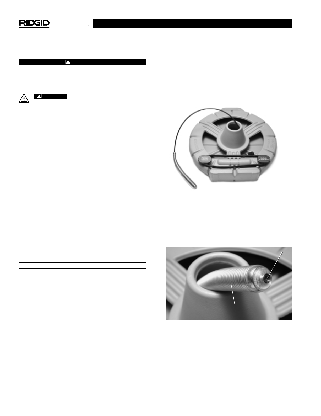
Figure 1 – Drum, Push Cable, Camera Head/Spring,
Interconnect Cord
1) Camera Head
The camera head (Figure 2) has adjustable lighting el-
ements and a highly scratch-resistant sapphire window
(Lens Port). The Camera is rated to a water depth of 330′
(100m).
Figure 2 – Camera Head
LED – Light Emitting Diode. The SeeSnake FlatPack
uses infrared LEDs that are invisible to the human
eye but provide the camera’s imaging sensor with plenty
of illumination for a clear picture. The Color FlatPack
uses white LEDs that are clearly visible.
LED Window – The donut shaped window that covers
and protects the LEDs from abrasion.
Specific Safety Information
CAUTION
Read this operator’s manual carefully before using
the product. Failure to understand and follow the
contents of this manual may result in electrical
shock, fire and/or serious personal injury.
Camera head can get HOT! Turn
OFF camera while not in use.
Equipment Safety
• Extension cords are not recommended unless they
are plugged into a Ground Fault Circuit Interrupter
(GFCI) found in circuit boxes or receptacles.
• Do not operate the system with electrical components removed. Exposure to internal parts increases
the risk of injury.
• Do not place the unit in water. Water entering the
housings will increase the risk of electrical shock.
• Do not use the unit as a chair or table. Dropping or
shocking the unit can result in damage to the unit,
which increases the risk of electrical shock.
• If used on a cart, product and cart should be
moved with care. Quick stops, excessive force and uneven surfaces may cause the product and cart
combination to overturn.
• Only the camera head and cable are waterproof.
The monitor is splash-resistant only when the Monitor
Shield is covering the monitor screen and the unit is
operating under battery power. Do not expose AC
adapter to damp conditions.
SAVE THESE INSTRUCTIONS!
Description, Specifications and
Standard Equipment
Description
The SeeSnake FlatPack pipe inspection system consists of the FlatPack drum which contains the camera
and push cable, and the Monitor Pack camera control
unit (CCU). The Monitor Pack has a built-in high-resolution monitor and can be powered from an AC adapter or
rechargeable battery.
The SeeSnake FlatPack pipe inspection system is designed for inspecting 11/2″ to 4″ (38mm to 102mm) drain
lines. Its flexible camera head can negotiate multiple
hard 90° bends and be pushed up to 100′ (30m).
The SeeSnake FlatPack drum is a UL Listed accessory, intended for use only with the following UL Listed SeeSnake
CAUTION
LED Window
Spring Assembly
Test Equipment Depot - 800.517.8431 - 99 Washington Street Melrose, MA 02176
FAX 781.665.0780 - TestEquipmentDepot.com
SeeSnake®FlatPack and Color FlatPack
Kollmann
Ridge Tool Company 5
Spring Assembly – Flexible stainless steel spring and associated components that hold the camera to the push
cable. It provides a flexible transition from camera to push
cable, and protects the terminations within the spring.
In Line Transmitter – Is contained within the spring assembly.
Safety Cable – Stainless steel cable within the spring
assembly that keeps the spring from over-extending
and ensures the camera’s internal connectors are not
stressed when pulling the camera out of a pipe.
2) Drum
Push Cable – (Figure 1) Terminates right behind the
spring. It has a high-strength fiberglass core stiff enough
to allow long distance pushing while flexible enough to
negotiate tight turns. The tough outer jacket is abrasion resistant.
Drum – The push cable is stored in the molded gray
drum. The drum is rust and dent-proof and keeps waste
water off your customers’ carpets.
Interconnect Cord – Stores on the drum and provides
the connection between the camera reel and the CCU.
(Figure 1)
Locking Sleeve – Found at the end of the Interconnect
Cord, it provides a solid connection between the CCU
and the reel.
NOTE! When attaching or removing the Interconnect Cord
from the CCU, ONLY turn the connector’s outer
locking sleeve! Bending or twisting the connector
body inside the locking sleeve will damage the
connector!
3) Monitor Pack Camera Control Unit
(CCU)
The Monitor Pack is a camera control unit (CCU) that
provides power to the camera reel, control of the camera’s light intensity and a built-in monitor for viewing
the image. The Monitor Pack (Figure 3) may be powered
by either a 120 volt or 230 volt AC source. A 14.4V
Makita®rechargeable battery can also power the system.
(See Table below.)
The following Makita®batteries are approved for use with
this system: 1422 (RIDGID P/N 83407), 1433 and 1434.
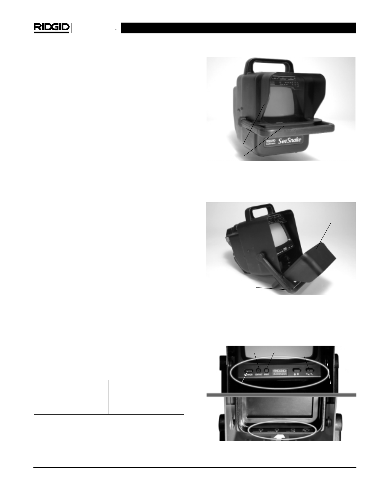
Monitor Shield – Protects the monitor and internal
electronics (Figure 3 and 4).
Figure 3 – Monitor Pack
Tilt Stand – The front handle attached to the monitor
shield also acts as a tilt stand for positioning the monitor
at different viewing angles (Figure 4).
Figure 4 – Monitor Shield and Tilt Stand/Handle
Monitor Controls – Brightness and contrast may be ad-
justed with the monitor controls. On the B&W version
there is also an image inverter and a Day/Night switch to
further adjust the image viewed on the screen. (Figure 5)
Figure 5 – Adjustment Controls for the B&W (Top) and
Color (Bottom) Monitor Screens
RIDGID Catalog Numbers Description
83407 14.4V Battery
83417 115V Charger
84112 230V Charger
Monitor Shield
and
Release Lever
Monitor Shield
Tilt Stand/Handle
Monitor Power
Contrast
Brightness
Image Invert
Day/Night Switch
Ridge Tool Company6
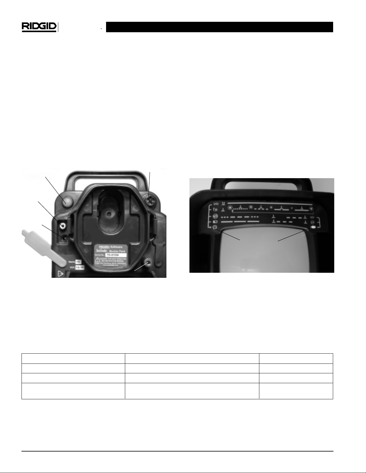
Red Multifunction Button (Figure 6) – This button serves
the following functions:
• Press and quickly release to turn the system power
ON/OFF.
• Press and hold to cycle through the brightness settings of the camera’s LED lighting.
• Press and hold for ~1 sec. to activate or de-activate
the In-Line Transmitter (See Table 1 for detailed in-
structions.)
NOTE! The B&W FlatPack uses infrared LEDs that are
invisible to the human eye; changes to the
brightness level will only be visible on the monitor screen.
Figure 6 – Monitor Pack Rear Panel
LED Indicators (Figure 7) – The LED indicators above
the monitor screen indicate the following operational
conditions:
RED • Steady Glow – Power ON
RED • Steady Flashing – Indicates low battery status
when running off the optional battery pack
RED • Flash S-O-S (3 short, 3 long, 3 short) pattern in
Morse Code – no video signal from the camera
head
WHITE • Steady Flashing – In-Line transmitter is active
RED • Rapid Flashing slowing from 8 to 4 flashes, 2
flashes, 1 flash, While pushing the red multi-
function button, indicates changes to the
brightness level of the camera’s LED lighting.
(Table 1)
Figure 7 – LED Indicators
SeeSnake®FlatPack and Color FlatPack
Kollmann
Button Press Duration Action LED Indicators*
Quick Press and Release (<1/2sec.) Toggles Power ON/OFF Red - Lit/Unlit
Medium Press and Release (
1
/2– 4 sec.) Toggles SeeSnake In-Line Transmitter ON/OFF White - Flashes slowly
Long Press and Release (>4 sec.) Cycles through LED brightness levels, Release when Red - Rapid flashing slowing
desired level is reached. to 4 flashes, 2 flashes, 1 flash
Table 1 - Multifunction Button
*LED Indicators - See Figure 6.
(Red)
(White)
LED Indicators
Multifunction
Button
Connector for the
Interconnect Cord
External
Power Jack
Video
In/Out Jack
Ground Reference (Future Expansion)

SeeSnake®FlatPack and Color FlatPack
Kollmann
Ridge Tool Company 7
Place the drum so the push cable is easy to manage as
you push the camera through the line. Two to three feet
(about one meter) from the access point is usually the optimal location.
The Monitor Pack can be tilted to several different viewing angles. When a battery is installed, it can be tilted to
rest on its rear supports (Figure 8). The front handle
attached to the monitor shield can also be used as a tilt
stand. Grasp the Monitor Shield Release Lever (Figure
3), pull it toward the handle to release the Monitor Shield,
and rotate the monitor shield down (Figure 4).
TIP: In brightly lit areas, point the monitor screen away
from bright light sources to reduce glare.
Figure 8 – Monitor Pack Tilted Using Rear Supports
Connections
Connect the Monitor Pack to an AC outlet using the
supplied AC adapter. If desired, you can install an optional Makita®14.4V rechargeable battery into the battery
holder on the rear of the unit instead of using the AC
adapter. (Figure 9)
If the AC adapter supplied is a universal type with detachable power cord, use only cord with Class II IEC
60320 connector and mains plug approved for the country where unit is used.
Figure 9 – Battery Holder
Specifications
Line Capacity.................11/2″ to 4″ (38 to 102 mm)
Max. Cable Length........100′ (30 m)
Weight...........................18 lbs (8.2 kg)
Dimensions
CCU Length..................14″ (35.6 cm)
Width...................7.5″ (19 cm)
Height..................10.25″ (26 cm)
Drum Depth...................7.5″ (19 cm)
Width...................24″ (61 cm)
Height..................25.75″ (65.4 cm)
Power Source................120V/60 Hz or 230V/50 Hz,
14.4 VDC Rechargeable
Battery (optional equipment)
Power Ratings
Monitor Pack .............14-16VDC, 15W
FlatPack Drum...........12VDC, 7W
Video Format.................EIA (CCIR Available)
NTSC (PAL Available)
Push Cable Diameter....0.26″ (6.6 mm)
Camera Depth Rating....Waterproof to 330′ (100 m)
Lighting..........................24 Infrared LEDs (B&W)
24 White LEDs (Color)
Oil Filled Tube...............USP Grade Mineral Oil
Operating Environment
Temperature..............32° F to 104° F (0°C to 40°C)
Altitude ......................Up to 6560 ft. (2000 m)
Transient
Over Voltage .............Installation Categories I
(1500V Phase to Earth)
Pollution Degree 2
Storage Temperature....-4°F to 140°F (-20°C to 60°C)
Humidity ........................30-90% RH
Standard Equipment
• Rust Proof Drum with Camera and Cable
• Monitor Pack with B&W or Color Monitor
• In Line Transmitter
• 115V Power Supply or 100-240V Power Supply
• Interconnect Cord
• Instructional Video
• Operator’s Manual
Set Up and Operation
Equipment Set Up
Misuse of the push cable will result in
breakage requiring factory service.
CAUTION
Ridge Tool Company8
NOTE! The Monitor Pack will not recharge the battery;
the battery must be removed from the Monitor
Pack for recharging. Use only the charger specified by the battery manufacturer!
Unwrap the Interconnect Cord from its holder on the
drum and plug its connector into the matching SeeSnake
System connector on the Monitor Pack. To join the connectors, make sure the red arrow on the connector is
facing up, push the connector straight in, and tighten the
locking sleeve. (Figure 10)
Figure 10 – Tightening the Locking Sleeve
If the connector does not push in easily, make sure the
guide pin on the Interconnect Cord’s connector is aligned
with the guide socket on the Monitor Pack’s connector.
(Figure 11)
Figure 11 – Guide Pin on the Interconnect Cord
NOTE! Twist only the outer locking sleeve! Bending or
twisting the connector body inside the locking
sleeve will damage the connector. When unplugging you may wiggle a little, if necessary, but do
not bend or twist.
NOTE! The Interconnect Cord should be disconnected
from the Monitor Pack whenever moving or transporting the system.
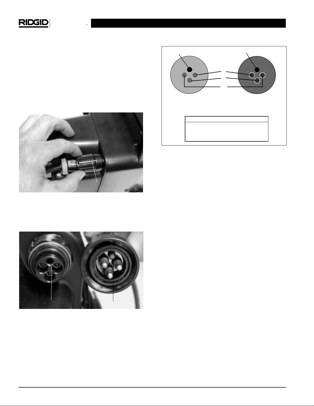
Figure 12 – Guide Pin/Socket Diagram
Operation
Press and release the multi-function button on the back
of the Monitor Pack (Figure 6) to turn the power ON. The
red LED indicator will light. You should see an image on
the monitor screen in a few seconds. If you do not,
check to make sure the monitor’s power switch is turned
ON. To turn the system OFF, press and quickly release
the multi-function button.
Put the camera head into the access point and adjust the
camera’s lighting if necessary. To adjust the camera’s
lighting, press and hold the red multi-function button.
After about four seconds, the red LED indicator on the
Monitor Pack will begin flashing rapidly. This indicates
that the camera’s LED lighting elements are cycling
through their brightness levels. When the image inside
the pipe looks good, release the red multifunction button.
TIP: When the Monitor Pack is turned ON, the cam-
era’s lighting will always be at full brightness, and in
most cases will not require adjustment.
If necessary, you may adjust the monitor’s image controls
to further improve the picture. The image controls are located on either the bottom front (B&W) or bottom rear
(color) of the monitor. See Figure 5.
Video Recording
When the Interconnect Cord is plugged into the Monitor
Pack, the Video In/Out jack functions as a Video Out
jack. An RCA cable can be used to connect this jack to
the “Video In” jack of a VCR for recording, or to another monitor. If connecting to another monitor, and it has
a High Z/Low Z switch, place the switch in the High Z position for the best video quality.
SeeSnake®FlatPack and Color FlatPack
Kollmann
Pin/Socket Function
1 ..............................Video Signal
2 ..............................+12 VDC
3 ..............................Neutral
Male Connector Pins
(Interconnect Cord)
Female Connector
Sockets (Connector
for Interconnect Cord)
Guide Pin
Guide Socket
3
2
1
Guide Socket
Guide Pin
Locking Sleeve

9
When the Interconnect cord is NOT plugged into the
Monitor Pack, the Video In/Out jack functions as a Video
In jack. An RCA cable can be used to connect this jack to
the “Video Out” jack of a VCR for reviewing a recording
you have made.
NOTE! The Interconnect Cord must be unplugged to play
back video from a VCR. If you attempt to play
back video while the camera’s Interconnect Cord
is plugged into the Monitor Pack, the monitor’s
image will be distorted.
At the Job Site
The camera pushes better when grip-style rubber
gloves are worn. It is much easier to get a grip on dirty
push cable, and the gloves also keep sludge off the hands.
Proper positioning of the equipment and pushing of
the cable will save time, be more comfortable, and
minimize the potential for equipment damage. (Figure
13.)
Set the monitor in an area where it is unlikely to
fall, and where it can be viewed while you are pushing the camera. A good location is right next to the
cleanout or entry point.
Set the reel about 2′ to 3′ (~1 meter) from the entry.
This will provide ample cable to grasp and will develop
momentum without having slack dragging on the ground.
When pushing, the end of your stroke should be as
close to the entry as possible (Figure 13). Standing too
far back with an excess of cable between your hands and
the entry may cause the cable to fold on itself outside the
entry and damage the cable (Figure 14).
Figure 13 – Equipment Set-Up
Figure 14 – Incorrect Hand Position on Push Cable
DO NOT Fold the push cable onto the sharp edge of
an entry. This can cause it to snap. Extreme caution
must be used to minimize the chance of bending the
push cable on sharp corners. This can cause push cable
failure. If the camera just does not seem to want to go any
farther, DO NOT FORCE THE CAMERA! If another entry
is available, try it, or run water down the line as explained below.
NOTE! Hands should be close to the line opening. DO
NOT catch the cable on the edge of an entry
and continue to push.
Always try to run water down the pipe undergoing inspection. This will keep the system much cleaner, and
allow you to push noticeably farther with less friction. This
will also help you locate the bottom of the pipe. This can
be accomplished by feeding a hose with a small amount
of flow into the entry or occasionally flushing a toilet
that drains to the pipe. If the water is preventing you from
seeing an area of importance, temporarily turn it off.
When inspecting a pipe, it is usually necessary to
give a little extra push in the bends. Back the camera
head approximately 6″ (15 cm) from the bend, if necessary, and give it a quick push, “popping” the camera
through a turn, using the least amount of force required.
Try to be as gentle as possible, and do not hammer or
snap the camera head through corners. In many instances, the best way to inspect a section of pipe is to
push the camera through quickly, then draw the camera
back home slowly and evenly. It is always easier to
control the camera when pulling than when pushing.
Make sure the sapphire window is clean prior to entry. In some cases a slight film of liquid detergent on the
lens port helps minimize the possibility of grease sticking
to the lens port.
SeeSnake®FlatPack and Color FlatPack
Kollmann
Test Equipment Depot - 800.517.8431 - 99 Washington Street Melrose, MA 02176
FAX 781.665.0780 - TestEquipmentDepot.com

SeeSnake®FlatPack and Color FlatPack
Kollmann
Ridge Tool Company10
Do not clear obstructions with the camera head!
This may cause premature failure to your camera
head. The SeeSnake
®
is a diagnostic tool that identifies problems. It should never be used to clear
obstructions. Other tools should be used to make effective repairs. (See Figure 15.)
Figure 15 – Do Not Clear Blockage with Camera Head
If local 120V (or 230V) AC power for the CCU is not
available, you can operate the system using a voltage converter that plugs into your vehicle’s cigarette
lighter. They convert your vehicles 12 volt DC to 120
volts (or 230V) AC.
The system can travel through multiple 45 and 90
degree bends and wyes. Do not, however, try to
force it through a P-trap or Tee if there is a large
amount of resistance.
Be careful in Tee-entries not to fold the camera
back on itself, this could cause the camera to get
caught. (see SeeSnake Tips & Tricks video).
The camera head can get HOT!
When finished with your inspection, or if taking
a prolonged break in the middle of the inspection,
turn off the system. If the camera sits in a pipe, or any
enclosed environment, heat will build-up. This may lead to
the camera head overheating which will cause fuzzy
lines to appear on the monitor. In the event this happens, turn off the system, remove the camera from the
pipe (or enclosed environment) and let the camera head
cool for 10 to 15 minutes. Running water into the line will
also help cool the camera head. Always use the minimum
illumination required to maximize picture quality and to
avoid excessive heat build-up.
Ask customers what is in the line, or what the line is
used for, prior to putting the camera into the line.
Avoid lines containing harsh solvents, chemicals, an
electrical charge and excessive heat.
NOTE! See the Video Tape that came with your system
for valuable Tips and Tricks on how to handle
different situations.
Transportation & Storage
The FlatPack can be laid on its back, set upright, or hung
by its handle during transport and storage. The
Interconnect Cord should always be disconnected from
the CCU and wrapped snugly around the storage hooks
on the drum. For temporary storage at the jobsite the
camera head can be tucked inside the cone (Figure
16) For transportation and storage between jobs the
camera head should be pushed down through the cone
and into the drum to protect the camera and prevent the
spring from taking a set (Figure 17).
The Monitor Pack should always be transported and
stored with the Interconnect Cord disconnected. Care
should be taken to secure the Monitor Pack so it does
not get thrown around during transport, and so that
other equipment does not fall on it. Store the system in
a cool, dry, shaded place.
Figure 16 – Camera Head Stowed Inside Cone
Figure 17
CAUTION

Ridge Tool Company 11
Centering Guides
Installing the SeeSnake
®
Star-Type Centering Guides
Centering guides can improve the picture by bringing the
camera closer to the pipe’s center, allowing the camera
to see an equal amount of the pipe wall in all directions. Centering guides also help by raising the camera
out of sludge that is often found below the water line. This
helps keep the lens cleaner, longer, reduces wear and
tear on the LED Ring. See Figure 18.
We recommend using centering guides whenever possible, but if you are having trouble pushing the camera in
a particular pipe, try it without the guides.
Figure 18 – Centering Guides improve vision by allow-
ing the camera to see an equal amount of
pipe wall in all directions and by raising the
camera out of sludge. They also reduce wear
on the LED ring.
Whether or not you use guides, how many you use,
and where you place them on the spring causes the
camera to behave differently. The best advice is to experiment and decide what’s best for the given job.
One centering guide near the front end of the camera may
bias the camera head upward. This could be beneficial if
you need to see the top of the pipe during your inspection.
Move the guide back a little and the camera head may
bias downward when you push and upward as you pull
back. This could help you see the top and bottom of
larger pipes more easily.
Two centering guides will tend to keep the camera head
aimed toward the center of the pipe, allowing you to
see more of the pipe at once.
Centering guides should be pre-stressed prior to use for
increased flexibility. To do this, slowly bend the spikes
back and forth from the tip (not the base) a few times before use. See Figure 19.
Figure 19 – Pre-stress tabs by placing your finger at the
top of the spike and slowly pushing the spike
90 degrees. Repeat in the other direction.
Star-type centering guide assembly consists of two parts two steel c-ring and the plastic centering guide. See
Figure 20.
Figure 20 – Star-Type Centering Guide Components. You
may use from one to three guides.
Installing Star-Type Centering Guides
1. Position a centering guide and two c-rings over the
spring, with the centering guide between the c-rings.
See Figure 21.
Figure 21 – Guide and C-Rings Positioned On Spring
Assembly.
2. Position the opening in the centering guide 180 degrees opposite the opening in the c-rings. See Figure
22.
3. Press the c-rings into the grooves on each side of the
centering guide until the c-rings snap into place. It’s
SeeSnake®FlatPack and Color FlatPack
Kollmann
C-Rings

Ridge Tool Company12
SeeSnake®FlatPack and Color FlatPack
Kollmann
easiest if you place the closed portion of the c-ring
into the groove and work toward the open end. See
Figure 22.
Figure 22 – Press the c-rings into the grooves on the
centering guide. Make sure the openings in
the c-rings are 180 degrees opposite the
opening in the pipe guide.
Removing Star-Type Centering Guides
1. Pry off each c-ring with the tip of a flat blade screwdriver inserted near the open end of the ring and
the base of the spikes. See Figure 23.
Figure 23 – Place flat tip of screwdriver between c-ring
and base of spike and pry c-ring out of
groove.
2. Slide the c-rings and centering guide over the camera
head.
Installing the SeeSnake®Compact, and
FlatPack Ball-Type Centering Guides
Ball-type centering guides consists of two halves that are
pre-assembled at the factory, and two steel clips that
hold the guide in place on the spring.
Figure 24 – Centering guides improve vision by allow-
ing the camera to see an equal amount of
pipe wall in all directions and by raising the
camera out of sludge. They also reduce
wear on the LED window.
Figure 25 – Retaining Rings in Locked Position
Figure 26 – Unlock Retaining Rings by pulling them up
with a flat-bladed screwdriver.
Open Side of Guide
Retaining Rings
Locked
Retaining Rings
Unlocked

Ridge Tool Company 13
Figure 27 – Slide Ball Guide over spring and push
Retaining Rings down to lock the guides
in place.
Maintenance and Cleaning
CAUTION
Make sure equipment is unplugged from power
source before performing maintenance or making
any adjustment.
Preventative Maintenance
Camera Head
1. The camera head requires little maintenance, other
than keeping the LED window and sapphire window
clean. Use a soft nylon brush, mild detergent, and rags
and sponges from the camera head.
2. When cleaning the camera, do not use scraping tools
as they may permanently scratch these areas.
NEVER USE SOLVENTS to clean any part of the system. Substances like acetone and other harsh
chemicals can cause cracking of the LED window,
which could affect waterproofing.
3. As you use the system more and more, you may be
surprised to find that scratches on the LED window
will have a minimal effect on the performance of the
lighting. DO NOT sand the LED window to remove
scratches, as it is part of the watertight housing.
4. Another good way to extend the life of the camera is
to avoid removing obstructions from pipe with the
camera head. (See Figure 15.)
Spring Assembly
The spring assembly is the area where foreign matter is
most likely to accumulate. Within the spring is the rubber
tube between the push cable and a connector. Should
sharp objects or harsh chemicals, such as solvents or
bleach, be allowed to remain in this area for long periods,
they may wear on these components. Stir in a bucket of
warm water and mild detergent to flush the spring area.
NOTE! Never use a water jetter to clean the spring as-
sembly. If a spring takes a set during storage, dip
it in hot water to straighten.
Push Cable and Drum
The push cable and drum require almost no maintenance. It is important, however, to keep the push cable
clean to spot any excessive cuts or abrasions, while
making it much easier to grasp and push.
NOTE! Whenever you are retrieving push cable into the
drum, an excellent way to cut down on cable
grime is to run it through a rag in the last hand that
touches the cable as it enters the reel.
For a more thorough cleaning, fill the drum with lukewarm
water and a mild detergent. Agitate the drum to help
loosen the grime. Pay out all the cable, drain the water
from the drum (Figure 28), and wipe out the inside of the
drum. Run a rag over the cable as you feed it back into
the drum.
Figure 28 – Open Rubber Plug to Drain Water
Monitor Pack
Wipe the Monitor Pack with a damp cloth. Clean the monitor screen with monitor wipes, which are available at
most computer and office-supply stores. Monitor wipes not
only clean the screen, but also help prevent dust build-up.
Always avoid dropping or shocking the Monitor Pack.
The abrasion resistant acrylic shield can be cleaned with
household glass cleaner and a soft damp cloth.
NOTE! Although the acrylic window resists scratching,
care should be taken to brush off excess abrasive particles prior to cleaning.
Locating Faulty Components
SeeSnake®FlatPack and Color FlatPack
Kollmann
For troubleshooting suggestions
at the end of the manual.
, please refer to Chart 1

Ridge Tool Company14
SeeSnake®FlatPack and Color FlatPack
Kollmann
Service and Repair
CAUTION
Tool should be taken to a RIDGID Independent
Authorized Service Center or returned to the factory. All
repairs made by Ridge service facilities are warranted
against defects in material and workmanship.
Test Equipment Depot - 800.517.8431 - 99 Washington Street Melrose, MA 02176
FAX 781.665.0780 - TestEquipmentDepot.com
 Loading...