

Page 1

Thermal Imagers Manual
RT-3, RT-5x, RT-7x and RT-9x
Thermal Imagers
www.GlobalTestSupply.com
• Français – 19
Page 2

RT-3, RT-5x, RT-7x and RT-9x Thermal Imagers
Table of Contents
Recording Form for Machine Serial Number ...................................................................................1
Safety Symbols ..................................................................................................................................2
General Safety Rules
Work Area Safety ............................................................................................................................2
Electrical Safety ..............................................................................................................................2
Personal Safety ...............................................................................................................................2
Equipment Use and Care................................................................................................................2
Service ............................................................................................................................................3
Specific Safety Information
Thermal Imager Safety....................................................................................................................3
Battery Safety..................................................................................................................................3
RIDGID Contact Information .............................................................................................................4
Description .........................................................................................................................................4
Controls...........................................................................................................................................4
Screen.............................................................................................................................................5
Specifications.....................................................................................................................................6
Standard Equipment .......................................................................................................................6
Installing The Lanyard .....................................................................................................................7
Powering the Unit ...............................................................................................................................7
Changing/Installing Battery .............................................................................................................7
Charging Battery .............................................................................................................................7
Pre-Operation Inspection ..................................................................................................................8
Set-Up And Operation Instructions ..................................................................................................8
Initial Start-Up
Turning ON And OFF ......................................................................................................................8
Menu ...............................................................................................................................................8
Quick Select Button.........................................................................................................................9
Measurements
Saving An Image.............................................................................................................................9
Setting Measuring Functions.........................................................................................................10
Image Gallery................................................................................................................................10
Setting The Scale ..........................................................................................................................11
Setting ScaleAssist........................................................................................................................11
Setting Emissivity And Reflected Temperature Coefficient (RTC)..................................................12
Selecting Color Palette ..................................................................................................................13
Setting Image Type........................................................................................................................13
Activating/Disabling The Zoom (RT-9x Only).................................................................................13
Activating The Differential Temperature.........................................................................................13
Activating/Disabling The Min/Max On Area Function.....................................................................14
Configuration.................................................................................................................................14
SuperResolution............................................................................................................................14
Save JPEG....................................................................................................................................15
Connectivity......................................................................................................................................15
Wi-Fi Connection - Using The App ................................................................................................15
USB Connections..........................................................................................................................15
Updating Thermal Imager Firmware..............................................................................................15
Ambient/Electrical Conditions .......................................................................................................15
Information ....................................................................................................................................16
Reset Options................................................................................................................................16
Storage..............................................................................................................................................16
Maintenance Instructions
Cleaning ........................................................................................................................................16
Reset Options................................................................................................................................17
Calibration .....................................................................................................................................17
Troubleshooting.............................................................................................................................17
Service And Repair .......................................................................................................................17
Optional Equipment .........................................................................................................................17
Disposal ............................................................................................................................................17
Battery Disposal ............................................................................................................................17
Approval And Certification .............................................................................................................18
Lifetime Warranty...............................................................................................................Back Cover
*Original Instructions - English
ii
999-995-119.10_REV. A
www.GlobalTestSupply.com
Page 3

Thermal Imagers
RT-3, RT-5x, RT-7x and RT-9x
Thermal Imagers
WARNI N G!
Read this Operator’s Man ual
carefully before using this
tool. Failure to understand
and follow the contents of
this manual may result in
electrical shock, fire and/or
serious person al injury.
Thermal Imagers
Record Serial Number below and retain product serial number which is located on nameplate.
Serial
No.
www.GlobalTestSupply.com
Page 4
RT-3, RT-5x, RT-7x and RT-9x Thermal Imagers
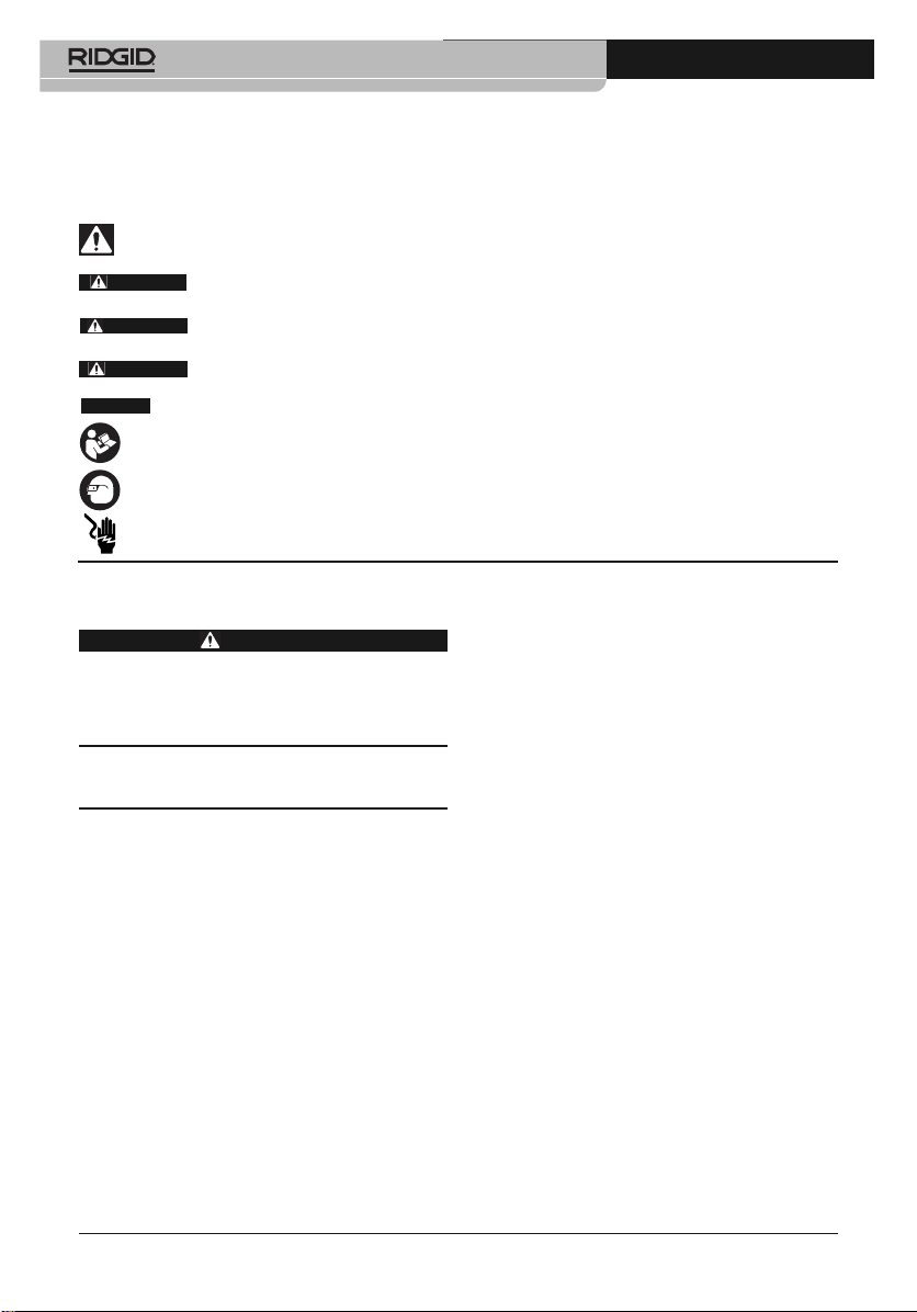
Safety Symbols
In this operator’s manual and on the product, safety symbols and signal words are used to communicate important safety information. This section is provided to improve understanding of
these signal words and symbols.
This is the safety alert symbol. It is used to alert you to potential personal injury hazards. Obey all
safety messages that follow this symbol to avoid possible injury or death.
DANGER
WARNING
CAUTION
NOTICE
DANGER indicates a hazardous situation which, if not avoided, will result in death or serious
injury.
WARNING indicates a hazardous situation which, if not avoided, could result in death or
serious injury.
CAUTION indicates a hazardous situation which, if not avoided, could result in minor or
moderate injury.
NOTICE indicates information that relates to the protection of property.
This symbol means read the operator’s manual carefully before using the equipment. The operator’s
manual contains important information on the safe and proper operation of the equipment.
This symbol means always wear safety glasses with side shields or goggles when handling or
using this equipment to reduce the risk of eye injury.
This symbol indicates the risk of electrical shock.
General Safety Rules
WARNING
Read all safety warnings and instructions.
Failure to follow the warnings and instructions may result in electric shock, fire
and/or serious injury.
SAVE ALL WARNINGS
AND INSTRUCTIONS FOR
FUTURE REFERENCE!
Work Area Safety
• Keep your work area clean and well lit.
Cluttered or dark areas invite accidents.
• Do not operate equipment in explosive at-
mospheres, such as in the presence of
flammable liquids, gases or dust. E quip -
ment can create sparks which may ignite the
dust or fumes.
• Keep children and by-standers a way
while operating equipment. Distrac tions
can cause you to lose control.
Electrical Safety
• Avoid body contact with earthed or
ground ed surfaces such as pipes, radiators, ranges and refrigerators. There is an
increased risk of electrical shock if your
body is earthed or grounded.
2
• Do not expose equipment to rain or wet
conditions. Water en tering equipment will in-
crease the risk of electrical shock.
Personal Safety
• Stay alert, watch what you are doing and
use common sense when operating equip ment. Do not use equipment while you are
tired or under the influence of drugs, alcohol or medication. A moment of inattention
while operating equipment may result in serious personal injury.
• Use personal protective equipment. Al -
ways wear eye protection. Protective equipment such as dust mask, non-skid safety
shoes, hard hat or hearing protection used for
appropriate conditions will reduce personal injuries.
• Do not overreach. Keep proper footing and
balance at all times. This enables better control of the power tool in unexpected situations.
Equipment Use and Care
• Do not force equipment. Use the correct
equipment for your application. The cor-
rect equipment will do the job better and safer
at the rate for which it is designed.
• Do not use equipment if the switch does
not turn it ON and OFF. Any tool that cannot
999-995-119.10_REV. A
www.GlobalTestSupply.com
Page 5

RT-3, RT-5x, RT-7x and RT-9x Thermal Imagers
be controlled with the switch is dangerous and
must be repaired.
• Remove the battery pack from the equip-
ment before making any adjustments,
chang ing accessories, or storing. Such
preventive safety measures reduce the risk of
injury.
• Store idle equipment out of the reach of
children and do not allow persons unfamiliar with the equipment or these instructions to operate the equipment. Equipment
can be dangerous in the hands of untrained
users.
• Maintain equipment. Check for missing parts,
breakage of parts and any other condition that
may affect the equipment’s operation. If damaged, have the equipment repaired before use.
Many accidents are caused by poorly maintained equipment.
• Use the equipment in accordance with
these instructions, taking into account the
working conditions and the work to be performed. Use of the equipment for operations
different from those intended could result in a
hazardous situation.
• Use only accessories that are recom-
mended by the manufacturer for your
equip ment. Accessories that may be suitable
for one piece of equipment may become hazardous when used with other equipment.
• Keep handles and grasping surfaces dry,
clean and free from oil and grease. Slippery
handles and grasping surfaces do not allow for
safe handling and control of the tool in unexpected situations.
Service
• Have your equipment serviced by a qual i fied repair person using on ly identical replacement parts. This will ensure that the
safety of the tool is maintained.
Specific Safety
Information
WARNING
This section contains important safety information that is specific to this inspection
tool.
Read these precautions carefully before
using the RIDGID
®
Thermal Imagers to re-
duce the risk of electrical shock or serious
personal injury.
SAVE ALL WARNINGS
AND INSTRUCTIONS FOR
FUTURE REFERENCE!
Keep this manual with the tool for use by the
operator.
Thermal Imager Safety
• Do not use the thermal imagers as a control device. Only use as a measuring device.
This will reduce the risk of damage or injury
in case of low battery, malfunction or false
measurement.
• Take appropriate precautions when work-
ing near electrical, moving or hot parts.
Close contact may cause electrical shock,
entanglement, burns and other serious injury.
Protective equipment may be required.
• Do not use this device for personal in-
spection or medical use in any way. This
is not a medical device. This could cause personal injury.
• Do not operate the equipment if operator
or device is standing in water. Do not expose the equipment to water or rain. This
increases the risk of electrical shock.
• Do not open or disassemble the thermal
Imager or battery. There are no user serviceable parts. Have repairs performed only at
authorized locations. Opening or disassembling the thermal imager or batteries may
cause electrical shock or personal injury.
• Do not use thermal imager or battery if ei-
ther has been dropped, modified or damaged in any way. Modified or damaged
thermal imager or battery increases the risk
of electrical shock.
• Do not probe thermal imager or battery
terminals with conductive objects. Shorting of terminals may cause sparks, burns or
electrical shock.
Battery Safety
• Follow all charging instructions and do
not charge or store the battery pack outside the temperature range specified in the
instructions. Charging or storing improperly
or at temperatures outside the specified range
may damage the battery and increase the risk
of battery leakage, electrical shock or fire.
999-995-119.10_REV. A
3
www.GlobalTestSupply.com
Page 6
RT-3, RT-5x, RT-7x and RT-9x Thermal Imagers
• Use appropriate Thermal Imager and Battery combinations. See batteries listed in
the Optional Equipment section for use with
the thermal imager. Using equipment and batteries that are not rated for use together can
cause the battery to burst, fire or personal injury.
• Avoid contact with battery fluids. Fluids
may cause burns or skin irritation. Thoroughly
rinse with water in case of accidental contact
with fluid. Consult doctor if fluid comes into
contact with eyes.
• When battery pack is not in use, keep it
away from other metal objects, like paper
clips, coins, keys, nails, screws or other
small metal objects that can make a connection from one terminal to another.
Shorting the battery terminals together may
cause burns or a fire.
• Do not burn battery or expose to high
temperatures. High temperatures can cause
the battery to explode.
• Properly dispose of batteries. Do not burn.
When disposing, place tape over battery terminals to prevent shorting. Batteries are Li-Ion
and should be recycled. Follow all appli cable
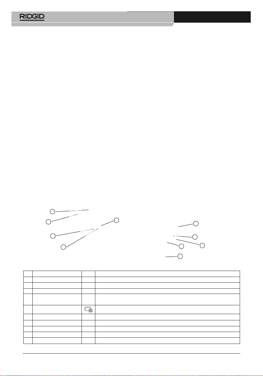
Controls
1
2
5
local regulations for disposal of batteries.
Refer to Disposal section.
RIDGID Contact
Information
If you have any question concerning this
®
RIDGID
product:
– Contact your local RIDGID distributor.
– Visit RIDGID.com to find your local RIDGID
contact point.
– Contact Ridge Tool Technical Service De -
partment at rtctechservices@emer son.com,
or in the U.S. and Canada call (800) 519-
3456.
Description
The RIDGID®Models RT-3, RT-5x, RT-7x and
RT-9x Thermal Imagers are handheld equipment
which detect infrared radiation and provide images for contactless determination of surface
temperature distribution.
Thermal images reveal different temperatures as
different colors.
6
3
4
No. Control/Parts Icons Description
1 Display — Displays infrared and real images, menu and functions.
2 USB Port Cover — Contains micro USB interface for power supply and connection to the computer.
3 Power/Escape Key Esc Power Key - Switch camera ON and OFF./Escape Key - Cancels action.
4 OK Key/Joystick OK
5 Quick Select Button Opens the function assigned to the quick select button.
6 Infrared Camera Lens — Takes infrared images.
7 Digital Camera Lens — Takes real images (RT-5x, RT-7x and RT-9x only).
8 Trigger — Saves the displayed image.
9 Battery Compartment — Holds the rechargeable battery.
10 Serial Number — Serial Number.
Figure 1 – Thermal Imager
4
OK Key - Open menu, select function, confirm setting./Joystick - Navigate within the
menu, highlight function, select color palette.
7
8
9
10
999-995-119.10_REV. A
www.GlobalTestSupply.com
Page 7
RT-3, RT-5x, RT-7x and RT-9x Thermal Imagers
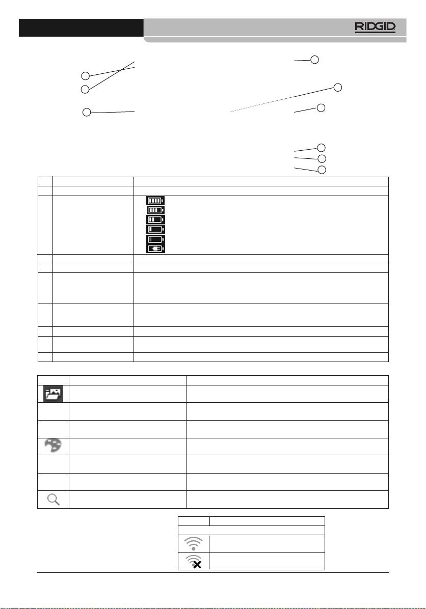
Screen
1
2
3
4
8
5
6
7
9
No. Screen Element Description
1 Status Bar In the status bar, information may be displayed depending on the setting.
2 • : Battery operation, capacity 75-100%
• : Battery operation, capacity 50-75%
Battery Capacity/ • : Battery operation, capacity 25-50%
Charge Status
• : Battery operation, capacity 10-25%
• : Battery operation, capacity 0-10%
• : Mains operation, battery is charging.
3 Image Display Infrared image or real image display.
4 °C or °F Temperature units.
• Grey characters: measuring range.
5 Scale
6 A, M or S A - automatic scale adjustment.
M - manual scale adjustment.
S - ScaleAssist is enabled.
• White characters: temperature margin of the image displayed, showing the mini mum/ max i mum reading (with automatic scale adjustment) or the selected minimum/maximum display value (with manual scale adjustment).
7 E ... Emissivity setting.
8
Point that temperature on screen is being measured. Round center indicates IFOV warner
Cursor
OFF, Square center indicates IFOV warner ON.
9 Quick Select Button Function Displays the chosen Quick select function.
Figure 2 – Thermal Imager Screen
Icon Menu Item Function
Image Gallery Opens an overview of saved images.
Scale (This function is only available
if the Image type is set to infrared)
Emissivity (This function is only available
if the Image type is set to infrared)
Set scale limits.
Set emissivity (E) and reflected temperature (RTC).
Palette Toggles the palette selection.
Adjustment (This function is only available Manual calibration. The camera automatically calibrates approximately every
available if the Image type is set to infrared) 60 seconds. If desired, manual calibration can be carried out at any time.
Image Type Alternately switches the image display between infrared and real image.
Zoom (RT-9x only) Enlarges the image section (2x, 3x, 4x).
Figure 3 – Quick Select Button Icons
Other Icons (Appear in Status Bar)
Icon Function
Wi-Fi icons
App is connected.
No connection to the App.
999-995-119.10_REV. A
5
www.GlobalTestSupply.com
Page 8
RT-3, RT-5x, RT-7x and RT-9x Thermal Imagers
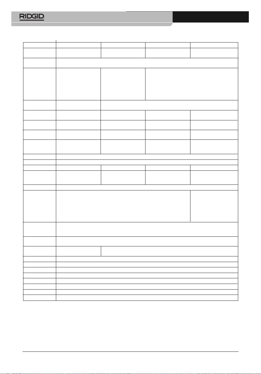
Specifications
Parameter RT-3 RT-5x RT-7x RT-9x
Measuring -4 to 536°F -22 to 1202°F -22 to 1202°F -22 to 1202°F
Range (-20 to 280°C) (-30 to 650°C) (-30 to 650°C) (-30 to 650°C)
-22 to -8°F (-30 to -21°C) Measuring Range ± 5.4°F (± 3°C)
• Single point • Single point • Single point • IFOV warner
• Cold spot • Cold spot • Cold spot • E-Assist
Measurement • Hot spot • Hot spot • Hot spot • Ambient Temperature,
Functions • Differential temperature • Differential temperature • Differential temperature Ambient Humidity and
• Scale Assist • Scale Assist • Scale Assist Electrical information can
• IFOV warner • IFOV warner be entered manually
• E-Assist for future reference
Display
Options • Real image
Infrared 160 x 120 pixels, 160 x 120 pixels, 240 x 180 pixels, 320 x 240 pixels,
Resolution 3.4 mrads 3.4 mrads 2.6 mrads 2.3 mrads
Super Resolution 320 x 240 pixels, 320 x 240 pixels, 480 x 360 pixels, 640 x 480 pixels,
Optional Feature 2.1 mrad 2.1 mrad 1.6 mrad 1.3 mrads
Thermal Sensitivity
(NETD)
Field of View (FOV)
/Min. Focusing 31° x 23° / <0.5 m 31° x 23° / <0.5 m 35° x 26° / <0.5 m 42° x 30° / <0.5 m
Distance
Spectral Range 7.5 - 14 μm
Focus Fixed Focus
Digital zoom — — — 2x, 3x, 4x
Visual Image Size/
Min. Focusing — 3.1 MP / 0.5 m 3.1 MP / 0.5 m 3.1 MP / 0.5 m
Distance
Display 8.9 cm (3.5") TFT
4 options: 10 options:
• Iron • Iron • Inverted grey
• Rainbow HC • Rainbow HC • High temp
Color Palettes • Cold-hot • Cold-hot • Humidity
• Grey • Grey • Rainbow
• Blue/red
• Sepia
• jpg
File format • bmt
• Option of exporting in, .bmt, .jpg, .png, .csv and .xls
Internal Mass
Storage
• USB 2.0 micro B
Battery Type Li-Ion Rechargeable Battery 2500 mAh / 3.7 V
Operating Time 4.0 h @ 20 °C
Operating Temp. 5 to 122 °F (-15 to 50 °C)
Storage Temp. -22 to 140 °F (-30 to 60 °C)
Humidity 20 - 80 %RH, Not Condensing
Protection Class IP 54
Weight (w/Battery) 1.12 lbs. (0.51 kg)
Dimensions 8.6" x 3.78" x 3.74" (219 x 96 x 95 mm)
± 2 °C / ± 2% (Whichever is greater)
Accuracy
• Infrared image
• Wi-Fi
Interface
• Infrared image
<120 mK <100 mK <90 mK <60 mK
• USB 2.0 micro B
2.8 GB
Standard Equipment
The RT-3, RT-5x, RT-7x and RT-9x Thermal Imagers comes with the following items:
• Carry Case
• Li-Ion Battery
• Lanyard
• USB Cable
• Operator’s Manual
• E-Assist Emissivity Decals (not with RT-3)
• AC Adapter
6
999-995-119.10_REV. A
www.GlobalTestSupply.com
Page 9

RT-3, RT-5x, RT-7x and RT-9x Thermal Imagers
NOTICE
This equipment is used to make temperature measurements. Incorrect set up and
use or improper application may result in incorrect or inaccurate measurements. Selection of
appropriate measurement methods for the conditions is the responsibility of the user.
Installing the Lanyard
Figure 4 – Installing the lanyard
Powering the Unit
WARNING
To reduce the risk of serious injury during
use, follow these procedures for proper
assembly.
Power is supplied via replaceable rechargeable
battery or the provided USB cable and AC adap ter (battery must be inserted).
The thermal imager is equipped with a buffer battery to maintain system data during power interruption (such as when the rechargeable battery
is removed changed).
Changing/Installing Battery
1. Switch unit OFF and remove any connections.
2. Slide the battery compartment cover down to
remove (Figure 5A).
3. Push the battery to release and remove (Fig-
ure 5B).
4. Insert the new battery and slide upwards until
it clicks into place (Figure 5C).
5. Close the battery compartment (Figure 5D).
A
Click
C
Figure 5 – Installing the Battery
Charging Battery
A new battery should be charged for 3 hours minimum before first use. If the battery has been
completely drained, the charging time is approx.
5 hours.
1. Open the USB port cover.
2. Connect the USB cable to the thermal imager USB Interface (Figure 6).
3. If using the AC Adapter, insert the USB cable
into the AC adapter.
4. With dry hands, either
• Insert the AC adapter into an appropriate
electrical outlet.
• Insert the USB cable into a powered USB
Port.
The battery will begin charging automati-
cally.
B
D
999-995-119.10_REV. A
Figure 6 – Charging the Battery
7
www.GlobalTestSupply.com
Page 10
RT-3, RT-5x, RT-7x and RT-9x Thermal Imagers
Pre-Operation Inspection
WARNING
Daily before use, inspect your Thermal
Imager and correct any problems to reduce the risk of serious injury from electric shock and other causes, and prevent
equipment damage.
1. Make sure the unit is OFF.
2. Remove the battery and inspect for signs of
damage. Replace if necessary. Do not use
if the battery is damaged.
3. Clean the equipment. See Maintenance Instructions. This aids inspection and helps
prevent the tool from slipping from your grip.
4. Inspect the locator for the following:
• Proper assembly, maintenance and com pleteness.
• Any broken, worn or missing parts.
• Inspect the camera lens for condensation.
To avoid damaging the unit, do not use the
camera if condensation forms inside the
lens. Let the water evaporate before using.
• Presence and readability of the product
and battery labels (Figure 1).
• Any other condition which may prevent
safe and normal operation.
If any problems are found, do not use the
thermal imager until the problems have
been repaired.
5. Inspect and maintain any other equipment
being used per its instructions to make sure
it is functioning properly.
Set-Up And Operation
Instructions
WARNING
Do not use the thermal imager as control
device. Only use as a measuring device.
8
This will reduce the risk of damage or injury in case of low battery, malfunction or
false measurement.
Follow set up and operating instructions to
reduce the risk of injury or incorrect measurements and to prevent tool damage.
1. Confirm have appropriate work area (See
General Safety Rules). Operate in clear,
level, stable, dry location.Do not use the
thermal imager while standing in water.
2. Determine the correct equipment for the application, see Description and Specifica-
tions sections.
3. Make sure all equipment has been inspected and set up as directed in their instructions.
Initial Start-Up
Turning ON And OFF
1. Turning ON: Remove the protective cap from
the unit lens. Press the Power Escape Key
( ). The thermal imager turns ON and the
start screen appears on the display. The thermal imager starts a warm up period that lasts
10 minutes. During the warm up and equalization period, the accuracy tolerance of the
thermal imager is greater than specification.
During the warm up period and approxi-
mately every 60 seconds during use, the
thermal imager automatically re-calibrates to
guarantee measuring accuracy. This is indicated by an audible "click" and the screen
image briefly freezing.
When the thermal imager is on, an image is
displayed on the screen. When turning unit
on for the first time, go to the “Configuration
Settings” to set language, time/date and temperature units, if needed
2. Turning OFF: Press and hold down the
Power/Escape Key ( ) until the progress bar
on screen is complete. The display goes OFF
and the camera is switched OFF.
Menu
Press OK key to open the menu. Move the Joystick up/down to highlight a function (red border)
(Figure 6). Press OK key to select the func tion.
Move the joystick to right to open the submenu
(marked with >). Press OK key to select the function.
To return to the main menu, move the joystick to
999-995-119.10_REV. A
www.GlobalTestSupply.com
Page 11

RT-3, RT-5x, RT-7x and RT-9x Thermal Imagers
the left or move the joystick to the menu bar and
press OK key.
Figure 7 – Menu Functions
Quick Select Button
The user can assign certain functions to the quick
select button, to call up at the touch of a button.
See Figure 3 for available functions.
1. Move the joystick to the right. The Configure
key selection menu appears. The activated
function is marked with a dot (●).
Figure 8 – Assigning Quick Select Function
2. Move the joystick up/down until the red box
appears around the required menu item.
Press OK key. The quick select button is assigned to the selected menu item. The icon
for the selected function is displayed bottom
right.
3. Press the Quick Select Button ( ). The
function assigned to the quick select button
is carried out.
Measurements
NOTICE
fire, furnaces) may damage the Detector. To prevent damage to the thermal imager, do not point
directly at the sun or other intense light sources.
Do not point at objects with temperatures outside
the measuring range of the tool, see specifications.
NOTICE
temperature measurements depends on the specific settings of the tool. Emissivity and Reflected
Temperature settings can significantly affect accuracy. If using the Automatic Scaling function,
the color assigned to a temperature is continuously changing, and color should not be used to
compare temperatures. Use a fixed scale if color
will be used to compare temperature.
These conditions can significantly affect the accuracy of measurements with thermal imagers:
• Emissivity and reflected temperature settings.
• When performing building thermography (in-
• Weather conditions that can create large
• The thermal imager requires a warm up and
• Distance to surface. The surface must be rec-
It is the operator’s duty to evaluate these conditions to assess the effect of the condition and
quality of the measurements.
Saving An Image
1. Focus on the area for which image is to be
2. Press Trigger. The image is automatically
Regardless of the image type set, an in-
High thermal radiation (e.g. due to sun,
The accuracy of the thermal imager
vestigating heat moving through the building
shell), a greater difference between inside
and outside temperature (ideal: ≥ 15°C/≥
27°F) improves accuracy.
changes in temperature (Such as intense
sunlight heating a surface, winds or rain that
can significantly cool a surface).
equalization period of up to 10 minutes after
being turned on to maximize accuracy.
ognizable and clear, and larger than the IFOV
warner cursor.
taken.
saved.
frared image is saved with an attached real
image (except RT-3).
999-995-119.10_REV. A
9
www.GlobalTestSupply.com
Page 12
RT-3, RT-5x, RT-7x and RT-9x Thermal Imagers
Figure 9 – Saving an Image
3. If a higher resolution is required, in the menu
under Configuration, select SuperResolution.
Image Gallery
Saved images can be displayed, analyzed or
deleted. The Image Gallery is not available when
Wi-Fi is enabled.
File Names
Setting Measuring Functions
1. Open the Measurement submenu. The submenu with the measurement functions opens.
Pixel Mark:
Single point measurement: the temperature
measuring point in the center of the image
is marked with white crosshairs and the
value is displayed.
Min/Max On Area (RT-9x Only):
Min/max on area: the minimum, maximum
and mean values for a selected area are
displayed.
Cold spot, Hot spot: the lowest or highest
temperature measuring point within the
range selection is marked with blue or red
crosshairs and the value is displayed.
Measuring Range: choose between two
temperature ranges. (RT-3 single temperature range only).
Differential Temperature: identifies the dif-
ference between two temperatures.
External Measurement Values: select Hu-
midity, Current, Voltage, Solar, Power, None.
IFOV: When on, the IFOV warner shows a
square center on the cursor that indicates
the smallest surface that can be used for
measuring temperature.
Zoom: enlarges the image section (2x, 3x,
4x), for RT-9x only.
2. Move the joystick up/down to select the required function and then press OK.
Figure 10 – Image Gallery
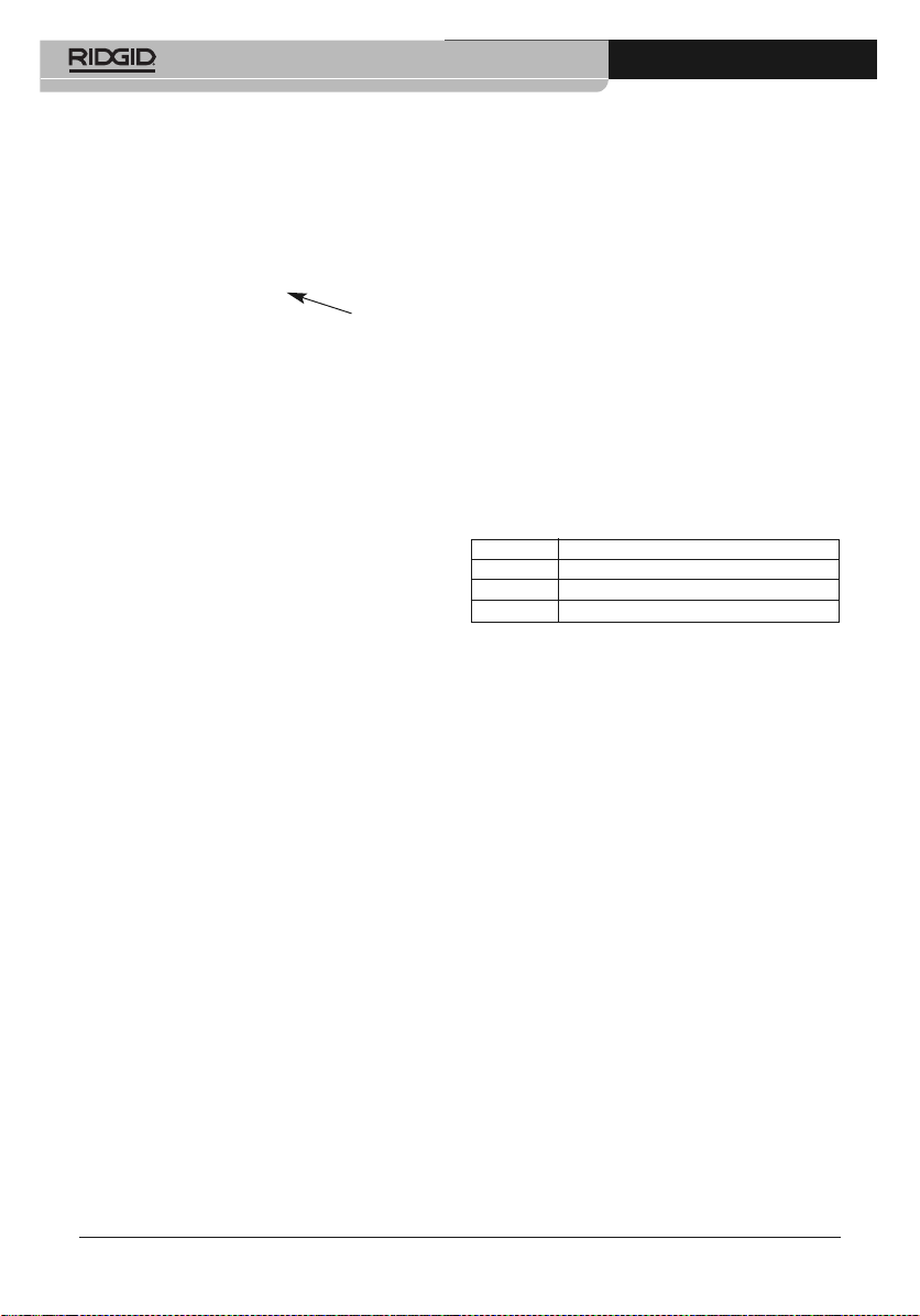
Designation Explanation
IR Infrared image with attached real image
000000 Consecutive number
SR Images captured with SuperResolution
File names can be changed by connecting the
thermal imager to computer and saving the file to
a new location on the computer.
Displaying A Saved Image
Saved images can be viewed and analyzed in the
image gallery.
When SuperResolution is enabled, 2 images are
saved in the image gallery (an IR image, and a
real image). The high-resolution SuperResolution
image is saved in the background. In the status
bar, the number of SuperResolution images to be
saved is displayed. A maximum five (5) SuperResolution images can be processed simultaneously.
1. Select the Image gallery function. All saved
images are displayed in the form of an infrared preview.
2. Move joystick to select an image.
3. Press OK to open the selected image. The
image is displayed.
Analyzing An Image
If an image is saved with SuperResolution, the
image gallery contains an (IR) image and a highresolution real image (SR). The images show the
10
999-995-119.10_REV. A
www.GlobalTestSupply.com
Page 13

RT-3, RT-5x, RT-7x and RT-9x Thermal Imagers
same image section. They can be displayed and
analyzed in the image gallery.
The measurement functions Single point measurement, Hot spot, Cold spot, Min/Max on Area
and Differential temperature can be used to analyze saved images.
Deleting An Image
1. Select the Image gallery function. All saved
images are displayed in the form of an infrared
preview.
2. Move joystick to select an image.
3. Press quick select button ( ).
4. Delete image? Message appears on screen.
Figure 11 – Deleting an Image
5. Press OK to delete the image.
Setting The Scale
The active scaling mode is displayed bottom right:
A - automatic scaling, M - manual scaling and S
- ScaleAssist.
Automatic scaling continuously adjusts the scale
to the readings presented, and the color assigned
to a temperature value changes.
Manual scaling defines fixed limit values, and the
color assigned to a temperature value is fixed (important for visual image comparisons).
ScaleAssist, is a standardized scale set based on
the inside and outside temperature.
Scaling influences the way the infrared image is
shown on the display but does not affect the
recorded measuring values.
Setting Automatic Scaling
1. Select the Scale function and press OK.
2. Move the joystick up or down until Auto is selected and then press OK. Automatic scaling
is activated. A is displayed bottom right.
Setting Manual Scaling
The lower limit value, the temperature range
(upper and lower limit value simultaneously) and
the upper limit value can be set.
1. Select the Scale function and press OK.
2. Move the joystick up/down until Manual is selected.
3. Move the joystick to the right, select Min.
Temp. (lower limit value). Move the joystick
up/down to set the value.
4. Move the joystick to the right, select Max.
Temp. (upper limit value). Move the joystick
up/down to set the value.
5. Press OK. Manual scaling is activated. M is
displayed bottom right.
Setting ScaleAssist
The ScaleAssist function calculates a display-neutral scale depending on the inside and outside
temperature. This is useful in identifying leak paths
in buildings. Ideally there should be a difference of
at least ≥ 10°C/≥ 18°F (ideal: ≥ 15°C/≥ 27°F).
1. Select the Scale function. Press OK.
2. In the mode menu, move the joystick up/down
until ScaleAssist is selected.
3. Move the joystick to the right, select Indoor
temperature. Move the joystick up/down to set
the value.
4. Move the joystick to the right, select Outdoor
temperature. Move the joystick up/down to set
the value.
5. Move the joystick to the left, back to the mode
menu.
6. Press Ok to activate ScaleAssist. S is displayed bottom right.
999-995-119.10_REV. A
11
www.GlobalTestSupply.com
Page 14
RT-3, RT-5x, RT-7x and RT-9x Thermal Imagers
Setting Emissivity And Reflected
Temperature Coefficient (RTC)
Emissivity
Emissivity is a term use to describe energy emitting characteristics of materials and has a value
ranging from 0 to 1. Emissivity values approaching
zero are typical for things with a high reflectivity,
like a mirror. Low reflectivity materials (such as
items painted flat black) have emissivity values
approaching 1. Emissivity is material-specific and
must be adjusted for correct measurement results. Improper emissivity values can cause significant temperature errors.
Non-metals (paper, ceramic, gypsum, wood,
paints and coatings), plastics and food typically
have high emissivity, which means that the surface temperature can be easily measured using
infrared.
Because of their low or non-uniform emissivity,
bright metals and metal oxides only have limited
suitability for infrared measurement. Highly inaccurate measurements should be expected. A
remedy for this is coatings that increase emissivity, e.g. paint or emission adhesive, which must
be applied to the object to be measured.
Alternately, the RT-5x, RT-7x and RT-9x thermal
imagers are equipped with ε-Assist, a feature that
will determine the emissivity using the ε-marker
affixed to the target surface.
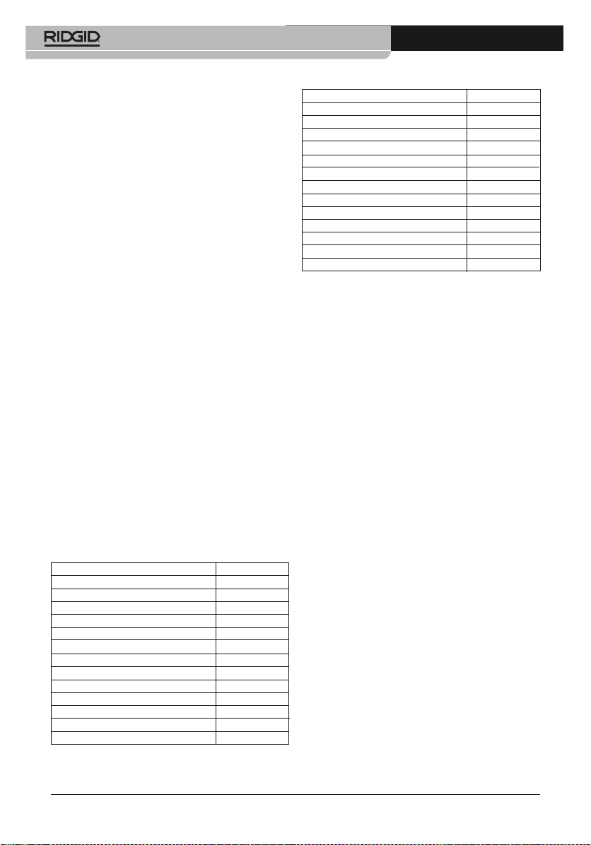
The following tables gives the standard preprogrammed materials and emissivity and typical
emissivity of common materials for use as a
guideline in setting emissivity.
Standard Preprogrammed Materials
Material (material temperature) Emissivity
Aluminum, bright rolled (170°C) 0.04
Cotton (20°C) 0.77
Concrete (25°C) 0.93
Ice, smooth (0°C) 0.97
Iron, emery-ground (20°C) 0.24
Iron with casting skin (100°C) 0.80
Iron with rolling skin (20°C) 0.77
Gypsum (20°C) 0.90
Glass (90°C) 0.94
Rubber, hard (23°C) 0.94
Rubber, soft grey (23°C) 0.89
Wood (70°C) 0.94
Cork (20°C) 0.70
12
Other Common Materials
Material (material temperature) Emissivity
Radiator, black anodized (50°C) 0.98
Copper, slightly tarnished (20°C) 0.04
Copper, oxidized (130°C) 0.76
Plastics: PE, PP, PVC (20°C) 0.94
Brass, oxidized (200°C) 0.61
Paper (20°C) 0.97
Porcelain (20°C) 0.92
Flat Black paint (80°C) 0.97
Steel, heat-treated surface (200°C) 0.52
Steel, oxidized (200°C) 0.79
Clay, burnt (70°C) 0.91
Transformer paint (70°C) 0.94
Brick, mortar, plaster (20°C) 0.93
Selecting/Setting The Emissivity
1. Select the Emissivity function.
2. Move the joystick up/down to select the desired material (with permanently set emissivity) and then press OK.
3. Move the joystick up/down until User defined
is selected. Move the joystick to the right until
desired emissivity value is selected. Manually
set value and press OK.
Reflected Temperature Coefficient (RTC)
Information:
The Reflected Temperature Coefficient (RTC) is
calculated based on the Reflected Temperature.
In most cases, the reflected temperature is identical to the ambient air temperature. Only when
objects with strong emissions at much lower temperatures (such as cloudless skies during outdoor
readings) or much higher temperatures (such as
ovens or machines) are in proximity to the object
being measured should the radiation temperature
of these sources be determined and used. The
reflected temperature has little effect on objects
with high emissivity.
Reflected temperature can be determined by:
1. Use a 12" x 12" (300 mm x 300 mm) minimum
sheet of aluminum foil. Crumple up the aluminum foil.
2. Uncrumple the aluminum foil. Attach the foil to
cardboard the same size.
3. Place the foil directly in front of the surface that
you want to measure the temperature of, foil
side out.
4. Set the thermal imager emissivity to 1.0.
5. Use the thermal imager to measure the
temperature of the middle of the foil. Use
999-995-119.10_REV. A
www.GlobalTestSupply.com
Page 15

RT-3, RT-5x, RT-7x and RT-9x Thermal Imagers
this as the Reflected Temperature entered
into the thermal imager.
6. Remove the foil from in front of the surface to
be measured. Enter an appropriate emissivity
for the surface to the be measured and take
temperature measurement.
Setting The RTC
1. Select the Emissivity function.
2. Move the joystick to the right until RTC is selected. Manually set desired value and press
OK.
Setting ε-Assist
ε-markers and the ε-Assist function of the Ther-
mal Imager can be used to automatically set the
emissivity and RTC. RTC can always be set.
Emissivity can only be automatically set if the surface temperature is more than 2°C different than
the reflected temperature. ε-markers can be used
on surfaces that have a consistent temperature of
less than 176°F (80°C) and a minimum size of at
least 4.75" x 4" (12 cm x 10 cm). Do not reuse ε-
markers.
1. Affix ε-marker to the center of the surface and
allow ε-marker and object temperature to
equalize for at least 30 seconds.
2. Select the Emissivity function.
3. Move the joystick to the right until ε-Assist is
selected and press OK. The screen will
change to the real image. A white box will appear on the real image. Place the box around
the ε-marker(see Figure 12). Thermal imager
should be 20" to 28" (0.5 to 0.7 m) away from
the ε-marker, and at a 10-30 degree angle.
reflected temperature. If emissivity cannot be
read, you will be prompted to manually enter
an emissivity.
5. Press OK key to accept the displayed values.
Selecting Color Palette
A variety of color palettes are supplied to meet
personal preferences. Palettes with greater color
variation may be beneficial when there are larger
temperature differences to better visualize the
temperatures.
This function is only available if the Image type is
set to infrared image.
1. Select the Palette function.
2. Move the joystick up/down to select the required color palette and then press OK.
Setting Image Type
The display can be switched between infrared
image and real image (digital camera). Model RT3 do not have real image function, it has only infrared image type.
1. Select the Image type function.
2. Move the joystick up or down and choose between infrared image or real image view.
3. Press OK key to confirm the selection.
Activating/Disabling The Zoom
(RT-9x only)
1. Move the joystick to the right and open the soft
key menu (quick select button).
2. Move the joystick down and select Zoom.
Then press OK.
3. Press quick select button ( ) to set the
Zoom.
Figure 12 – Using ε-markers
4. The thermal imager will automatically read the
ε-marker and populate the emissivity and the
999-995-119.10_REV. A
www.GlobalTestSupply.com
Activating The Differential
Temperature
Differential temperature enables the temperatures
between two measuring points to be calculated
and shown in the status bar.
1. Open Menu.
2. Move the joystick down and select Measurement. Then press OK or move the joystick to
the right.
3. Move the joystick down and select Differential
temperature. Then press OK. The Differential
Temperature menu will appear. The menu will
13
Page 16

RT-3, RT-5x, RT-7x and RT-9x Thermal Imagers
not be seen when measurements are being
made but pressing any key will bring the
menu back up.
4. Move the joystick down/up and select which
differential temperature is to be calculated
(Point-Point, Point-Value, Point-RTC). Then
press OK.
5. Point-Point Selection:
a. Move the joystick to the right, select meas-
uring point 1 and press OK. Move the
measuring point to the live image using the
joystick and press OK.
b. Move the joystick to the right, select meas-
uring point 2 and press OK. Move the
measuring point to the live image using the
joystick and press OK.
6. Point-Value Selection:
a. Move the joystick to the right and select
measuring point 1 and press OK. Move the
measuring point in the image using the joystick and press OK.
b. Move the joystick to the right and set the
value manually.
7. Point-RTC Selection:
a. Move the joystick to the right and select
measuring point 1 and press OK. Move the
measuring point in the image using the joystick and press OK.
b. Move the joystick to the right and set the
value manually.
8. End measurement: Move the joystick to the
right, press End.
Activating/Disabling The
Min/Max On Area Function
1. Open Menu.
2. Move the joystick down and select Measurement. Then press OK or move the joystick to
the right.
3. Move the joystick down and select Min/Max
on Area. Then press OK or move the joystick
to the right.
4. Select Min/Max on Area and press OK to activate or disable the function.
a. Select Hot spot/Cold spot and press OK to
activate or disable the function.
b. Select Hide all and press OK to disable all
functions for the measuring range.
Configuration
Country Settings
The user interface language can be set.
1. Select the Country settings function.
2. Move the joystick up/down to select the desired language and then press OK.
Set Time/Date
The time and date format are set automatically
based on the selected user interface language.
1. Select the Set time/date function.
2. Move the joystick to the right/left to select the
desired setting option.
3. Move the joystick up/down to set the value.
4. After setting all values, press OK.
Power-Save Options
The illumination intensity of the display can be set.
A lower intensity increases the battery life. The
time until automatic switch-off can be set.
1. Select the Power-save options function.
2. Move the joystick up/down to select the desired intensity level and then press OK.
SuperResolution
SuperResolution is a technology to improve
image quality. Each time a SuperResolution
image is recorded, a sequence of images is
saved and used to calculate an image with four
times more resolution. The geometric resolution
(IFOV) is improved by a factor of 1.6. SuperResolution images take longer to process, which will
be indicated in the status bar. Up to five SuperResolution images can be processed at one time.
To use the function, the camera should be handheld and the objects to be imaged should not
move.
1. Open the SuperResolution function.
2. Press OK to activate or disable the function.
Full Screen Mode
1. Select the Full screen mode function.
2. When Full Screen Mode is activated, the scale
and icon for the quick select button are hidden.
When a key is pressed, these elements are
displayed briefly.
14
999-995-119.10_REV. A
www.GlobalTestSupply.com
Page 17

RT-3, RT-5x, RT-7x and RT-9x Thermal Imagers
Save JPEG
Infrared images are saved in BMT (image with all
temperature data) format. BMT format images
can only be accessed with special software (see
Connectivity Section). The image can also be
saved in JPEG format (without temperature data)
at the same time. The image content corresponds to the infrared image shown on the display, including scale display and image marks for
the selected measuring functions. The JPEG file
is saved under the same file name as the associated BMT file and can be opened without special software.
1. Open the Save JPEG function and press OK.
2. Move the joystick up/down until ON/OFF is
selected and press OK.
3. Add a date/time stamp to a JPEG file, if required. Turn function ON/OFF for this.
Connectivity
Wi-Fi Connection - Using The App
The RIDGID®Models RT-5x, RT-7x and RT-9x
Thermal Imagers includes Wi-Fi technology allowing wireless data transfer to properly equipped
smartphones or tablets (“device”) running iOS or
Android operating systems.
Compatibility: Requires iOS 8.3 or later/Android
4.3 or later.
1. Download the appropriate RIDGID
your smartphone or tablet by going to
http://www.RIDGID.com/Thermal.
2. Open Menu.
3. Move the joystick down and select Configuration. Then press OK or move the joystick to the
right.
4. Move the joystick down and select Connectivity. Then press OK or move the joystick to the
right.
5. Move the joystick down and select Wi-Fi.
Then press OK. Tool Wi-Fi is now on, and a
Wi-Fi equipped device can find and pair with
the tool.
6. In the Wi-Fi settings of your device, select desired RIDGID tool. Refer to your device instructions for specific information on how to
connect via Wi-Fi. Once connected, the App
is connected symbol appears on screen.
7. After the initial pairing, most devices will automatically connect to the Tools when the Wi-Fi
999-995-119.10_REV. A
®
app to
is active and in range. Thermal imager should
be less than 33 ft. (10 m) from the device to
be detected. Any obstacle between the tool
and device can reduce the operational range.
8. Follow the app instructions for proper use.
iOS is registered trademark of Apple Inc.
Android and the Android logo are trademarks of
Google Inc.
USB Connection
The thermal imager can be connected to a computer or similar device using the USB cable (Fig-
ure 13). It will be recognized as a storage device
and files can be accessed like any other files. Go
to http://www.RIDGID.com/Thermal to download
software (IR-Soft) for use with the BMT files from
the thermal imagers. See Save JPEG Function to
save images as .jpeg files.
Figure 13 – Connecting USB Cable to Imager
Updating Thermal Imager
Firmware
From time to time the thermal imager firmware
(software) may need to be updated. Updated
thermal imager firmware, if available, will be found
at http://www.RIDGID.com/Thermal. Go to “Information” in the menus to see current firmware version. Download the updated firmware and using
the USB connection, save it to the thermal imager
memory. Disconnect the USB cable and restart
the thermal imager.
Ambient/Electrical Conditions
Values for ambient temperature and humidity and
electrical conditions can be entered manually and
will be recorded in the file for future reference
(such as for reports). Manually entering the am-
15
www.GlobalTestSupply.com
Page 18

RT-3, RT-5x, RT-7x and RT-9x Thermal Imagers
bient conditions does not change the thermal imager output.
1. Go to Menu, Configuration, Ambient condi-
tions.
2. Move the joystick as necessary to set the values.
3. Press OK.
Information
The following instrument information is displayed:
• Device data (e.g. serial number, device name,
firmware version)
• Options
• Measurement functions
• Wi-Fi
• Radio certifications
• Legal information
Reset Options
Reset Counters
NOTICE
numbering) of the images starts from the beginning. The already saved images with the same
name will be overwritten. Back up all saved images before resetting the counter to prevent possible overwriting.
1. Open Menu and press ok.
2. Move the joystick up/down until configuration
3. Move the joystick to the right, select Reset
4. Reset image counter? is displayed on the
5. Press OK to apply factory settings.
6. Press Esc to cancel the process.
Factory Settings
The instrument settings can be reset to the factory settings. Time/date, country settings and
counter are not reset.
1. Open Menu and press ok.
2. Move the joystick up/down until configuration
3. Move the joystick to the right, select Reset op-
4. Move the joystick up/down to select the Fac-
16
After a reset, the naming (consecutive
is selected.
counter.
screen.
is selected.
tions.
tory settings function.
5. Apply factory settings? is displayed on the
screen.
6. Press OK to apply factory settings.
7. Press Esc to cancel the process.
Formatting
The image memory can be formatted to remove
all images from the imager. When formatting, all
data saved in the memory is lost. Back up all
saved images before formatting to prevent loss of
data. Formatting does not reset the counter.
1. Open Menu and press ok.
2. Move the joystick up/down until configuration
is selected.
3. Move the joystick to the right, select Reset options.
4. Move the joystick up/down to select the Format function.
5. Format memory? is displayed on the screen.
6. Press OK to format the memory.
7. Press Esc to cancel the process.
Storage
Remove battery from tool. Store the Thermal Imagers in case. Avoid storing in extreme heat or
cold.
WARNING
that is out of reach of children and people unfamiliar with the RIDGID Thermal Imagers.
The thermal imagers are dangerous in the
hands of untrained users.
Store tool in a dry, secured area
Maintenance
WARNING
Remove battery from tool before cleaning.
Cleaning
Do not immerse the thermal imagers in water.
Close the battery cover and USB port cover.
Wipe off dirt with a damp soft cloth. Avoid rubbing too hard. Do not use aggressive cleaning
agents or solutions.
Gently clean the display screen with a clean dry
cloth. Avoid rubbing too hard.
If the infrared camera lens is dirty, clean it with
an alcohol lens wipe. Treat the instrument as you
would a telescope or camera.
999-995-119.10_REV. A
www.GlobalTestSupply.com
Page 19
RT-3, RT-5x, RT-7x and RT-9x Thermal Imagers
Reset Options
Refer to the Other Settings section.
Calibration
The Thermal Imagers are factory calibrated and
only require recalibration if repaired.
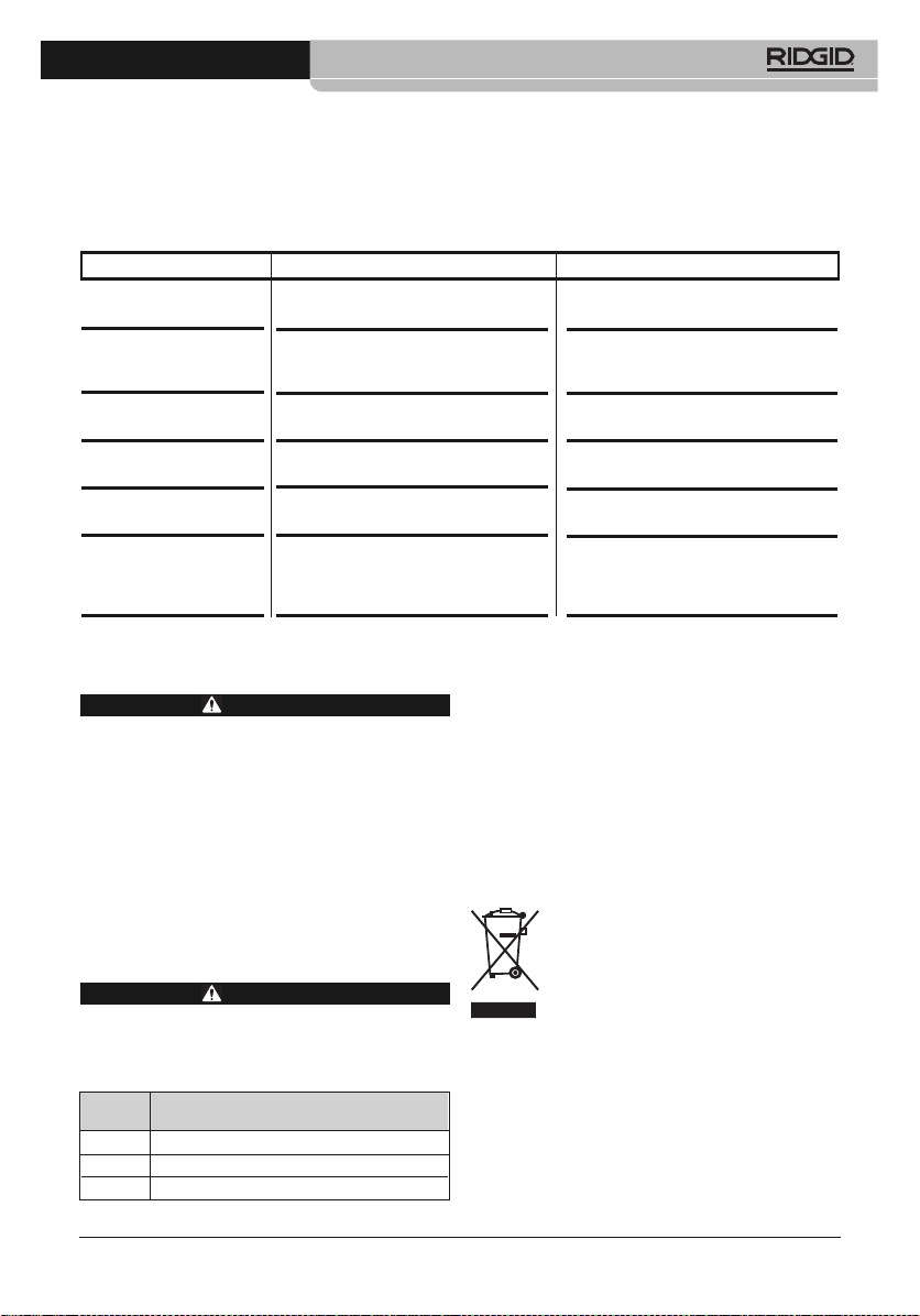
Troubleshooting
SYMPTOM POSSIBLE REASON SOLUTION
‘Error! Memory full!’ is
displayed.
Error! Permissible
instrument temperature
exceeded!’ is displayed.
‘~’ is displayed before a
value.
‘---‘ or ‘+++’ is displayed
instead of a value.
‘xxx’ is displayed instead
of a value.
Automatic zeroing (audible click and brief image
freeze) is carried out
very frequently.
Service And Repair
Improper service or repair can make the
machine unsafe to operate.
Service and repair on the thermal imagers must
be performed by a RIDGID Independent Service
Center. Use only RIDGID service parts.
For information on your nearest RIDGID Independent Service Center or any service or repair
questions, see Contact Information Section in
this manual.
Optional Equipment
To reduce the risk of injury, only use accessories specifically designed and recommended for use with the RIDGID Thermal
Imagers, such as those listed.
Catalog
No. Description
59658 Li-Ion rechargeable battery 2500 mAh/3.7 V
59663 Battery Charger
59668 Pack of 10 E-Markers (For E-Assist)
999-995-119.10_REV. A
Insufficient memory available.
Ambient temperature too high.
Value is outside the measuring range.
Value is outside the measuring range and
the extended display range.
Value cannot be calculated.
Camera is still in its warm-up period (10
minutes).
WARNING
WARNING
Transfer images to the PC or delete.
Switch off the camera, allow the instrument to cool down and observe the permissible ambient temperature.
Extended display range with no guarantee of accuracy.
Use the unit as per Measuring Range,
see Specifications.
Check parameter settings for
plausibility.
Wait until the warm-up period has
passed.
For a complete listing of RIDGID equipment avail able for this tool, see the Ridge Tool Cata log online at RIDGID.com or see Contact Information.
Disposal
Parts of this tool contain valuable materials and
can be recycled. There are companies that specialize in recycling that may be found locally. Dispose of the components in compliance with all
applicable regulations. Contact your local waste
management authority for more information.
For EC Countries: Do not dispose of
elec trical equipment with household
waste!
According to the European Guide line
2012/ 19/EU for Waste Elec trical and
men tation into national legislation, electrical
equipment that is no longer usable must be collected separately and disposed of in an environmentally correct manner.
Battery Disposal
Electronic Equipment and its imple -
For USA and Canada: The RBRC™
(Rechargeable Battery Recycling Corporation) Seal on the battery packs
means that RIDGID has already paid
17
www.GlobalTestSupply.com
Page 20
RT-3, RT-5x, RT-7x and RT-9x Thermal Imagers
the cost of recycling the lithium-ion battery packs
once they have reached the end of their useful life.
RBRC™, RIDGID
®
, and other battery suppliers
have developed programs in the USA and Canada
to collect and recycle rechargeable batteries.
Normal and rechargeable batteries contain materials that should not be directly disposed of in
nature, and contain valuable materials that can
be recycled. Help to protect the environment and
conserve natural resources by returning your
used batteries to your local retailer or an authorized RIDGID service center for recycling. Your
local recycling center can also provide you with
additional drop off locations.
RBRC™ is a registered trademark of the Re chargeable Battery Recycling Corporation.
For EC countries: Defective or used battery
packs/batteries must be recycled according to
the guideline 2006/66/EC.
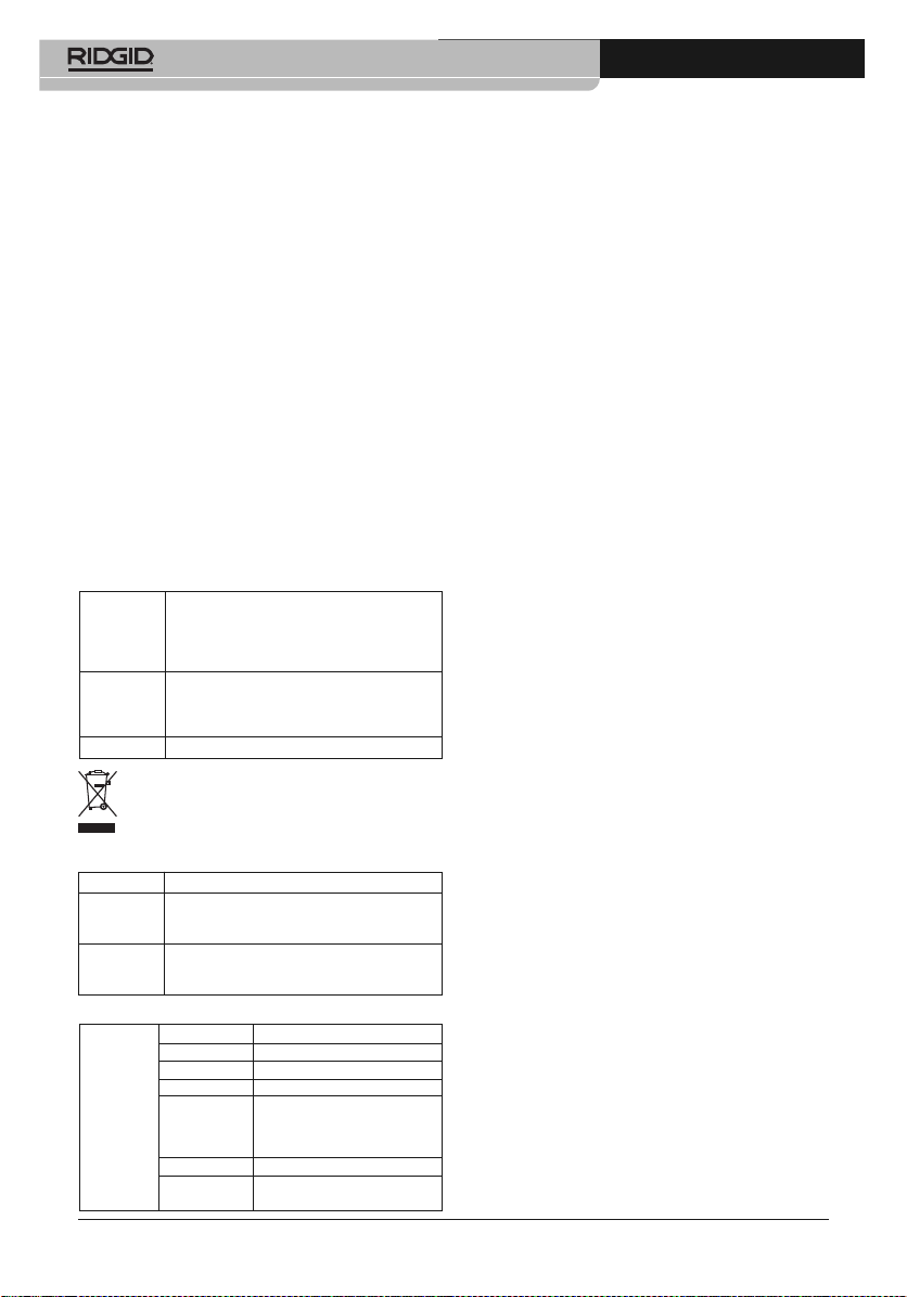
Approval And Certification
Ridge Tool Company (RIDGID)
edges that the re-sale, export, import etc. in particular in countries without
wireless permits, is his responsibility.
Country Comments
USA Contains FCC ID: TFB-TIW1-01
IC Warnings
Bluetooth
WI 53012-2636 USA
18
RT-3
Product
RT-5x
RT-7x
RT-9x
57533
57528
Mat.-No.
57523
57518
Date 17.05.2017
The use of the wireless module is subject to the regulations and
stipulations of the respective country of use, and the module may
only be used in countries for which a country certification has
been granted. The user and every owner has the obligation to adhere to these regulations and prerequisites for use, and acknowl-
Canada Contains IC: 5969A-TIW101
IC: 22560-2017RTFAM
IC Warnings
FCC ID: 2AECA-2017RTFAM
FCC Warnings
Wi-Fi / Feature Values
®
Information
radio class WLAN 2.4 GHz IEEE 802.11 b/g
radio module LSR
company W66 N220 Commerce Court
RF Band WLAN: 2412 – 2480MHz
power output WLAN: 20dBm
[E.I.R.P]
Wi-Fi range typical 15 m
radio type TiWi-BLE
Cedarburg,
RSS-Gen & RSS-247 statement:
This device complies with Industry Canada licence-exempt RSS
standard(s). Operation is subject to the following two conditions:
(1) this device may not cause interference, and
(2) this device must accept any interference, including interfer-
ence that may cause undesired operation of the device.
Caution: Radio Frequency Radiation Exposure.
This equipment complies with IC radiation exposure limits set
forth for an uncontrolled environment and meets the IC radio frequency (RF) Exposure Guidelines. This equipment should be installed and operated keeping the radiator at least 12 cm or more
away from person’s body in normal use position.
Co-Location:
This transmitter must not be co-located or operated in conjunc-
tion with any other antenna or transmitter.
FCC Warnings:
Information from the FCC (Federal Communications Commission)
For your own safety
Shielded cables should be used for a composite interface. This is to
ensure continued protection against radio frequency interference.
FCC warning statement
This equipment has been tested and found to comply with the limits
for a Class B digital device, pursuant to Part 15 of the FCC Rules.
These limits are designed to provide reasonable protection against
harmful interference in a residential installation. This equipment
generates, uses and can radiate radio frequency energy and, if not
installed and used in accordance with the instructions, may cause
harmful interference to radio communications. However, there is
no guarantee that interference will not occur in a particular install ation. If this equipment does cause harmful interference to radio
or television reception, which can be determined by turning the
equipment off and on, the user is encouraged to try to correct the
interference by one or more of the following measures:
• Reorient or relocate the receiving antenna.
• Increase the separation between the equipment and receiver.
• Connect the equipment into an outlet on a circuit different from
that to which the receiver is connected.
• Consult the dealer or an experienced radio/TV technician for help.
Caution
Changes or modifications not expressly approved by the party
responsible for compliance could void the user's authority to operate the equipment. Shielded interface cable must be used in
order to comply with the emission limits.
Warning
This device complies with Part 15 of the FCC Rules.
Operation is subject to the following two conditions:
(1) this device may not cause harmful interference, and
(2) this device must accept any interference received, including
interference that may cause undesired operation.
Caution: Radio Frequency Radiation Exposure
This equipment complies with FCC radiation exposure limits set
forth for an uncontrolled environment and meets the FCC radio
frequency (RF) Exposure Guidelines. This equipment should be
installed and operated keeping the radiator at least 12 cm or more
away from person´s body in normal use position.
Co-Location:
This transmitter must not be co-located or operated in conjunction with any other antenna or transmitter.
999-995-119.10_REV. A
www.GlobalTestSupply.com
 Loading...