

Page 1

Tapping Tool
OPERATOR’S
MANUAL
RT3422
WARNING!
Read this Operator’s Manual
carefully before using this tool.
Failure to understand and follow the contents of this manual
may result in extensive property damage and/or serious
personal injury.
99 Washington Street
Melrose, MA 02176
Phone 781-665-1400
Toll Free 1-800-517-8431
Visit us at www.TestEquipmentDepot.com
Page 2

Ridge Tool Company2
RT3422 Tapping Tool
General Safety Information
WARNING! Read and understand all instructions. Failure
to follow all instructions listed below may result in propery damage and/or serious
personal injury.
SAVE THESE INSTRUCTIONS!
Work Area Safety
• Keep your work area clean and well lit. Cluttered
work area invites accidents.
• Keep bystanders, children, and visitors away while
operating a tapping tool. Distraction can result in improperly using the tool.
Personal Safety
• Stay alert, watch what you are doing and use
common sense when operating a tapping tool.
Do not use tool while tired or under the influence
of drugs, alcohol, or medications. A moment of
inattention while operating tools may result in serious
personal injury.
• Dress properly. Do not wear loose clothing or
jewelry. Contain long hair. Keep your hair, clothing, and gloves away from moving parts. Loose
clothes, jewelry, or long hair can be caught in moving
parts.
• Do not over-reach. Keep proper footing and bal-
ance at all times. Proper footing and balance enables
better control of the tool in unexpected situations.
• Use safety equipment. Always wear eye protection.
Dust mask, non-skid safety shoes, hard hat, or hearing
protection must be used for appropriate conditions.
Tool Use and Care
• Do not force tool. Use the correct tool for your application. The correct tool will do the job better and
safer at the rate for which it is designed.
• Store idle tools out of the reach of children and
other untrained persons. Tools are dangerous in
the hands of untrained users.
• Maintain tools with care. Keep cutting tools sharp
and clean. Properly maintained tools with sharp cutting
edges are less likely to bind and are easier to control.
• Check for misalignment or binding of moving
parts, breakage of parts, and any other condition
that may affect the tools operation. If damaged,
have the tool serviced before using. Many acci-
dents are caused by poorly maintained tools.
• Use only accessories that are recommended by
the manufacturer for your model. Accessories that
may be suitable for one tool may become hazardous
when used on another tool.
• Keep handles dry and clean; free from oil and
grease. Allows for better control of the tool.
Service
• Tool service must be performed by qualified repair
personnel. Service or maintenance performed by
unqualified repair personnel could result in injury.
• When servicing a tool, use only identical replace-
ment parts. Follow instructions in the Maintenance
Section of this manual. Use of unauthorized parts or
failure to follow maintenance instructions may create
a risk of injury.
Specific Safety Information
WARNING
Read and follow safety labels on the tool! Know
the function of all parts before using this tapping
tool.
Operator Training
WARNING
Cutting into pipe containing liquids or gases under
pressure is potentially hazardous. Correct procedures must be followed in the use of this
equipment to maintain a safe working environment and prevent serious personal injury.
No person should use this tool who is not fully
trained in the proper operating procedure and
who is not fully aware of the potential hazards
connected with work on pipe containing liquids or
gases under pressure.
The purchaser of this equipment is responsible for
how this equipment is used and the training and
competence of the operators.
Should any difficulty arise at any time in the use of
this equipment, please contact Ridge Tool immediately!
Page 3

WARNING
• Read operators manual. Operator must be properly trained before using tool.
• Wear eye protection.
• Do not exceed pressure and temperature ratings of
the tool and any attachment, valve or fitting. Only
tap into lines that contain specified media.
Model RT 3422 Tapping Tool
Water: 500 psig @ 100°F (40°C)
Air, Steam, Natural Gas: 150 psig @ 370° F (172°C)
Tapping Tool Safety
1. Only trained personnel should use this tapping
tool. Incorrect use of this tool can result in serious
personal injury, environmental damage, and/or property damage.
2. Always wear eye protection. Cutters and drills are
hard and can shatter.
3. Do not exceed recommended pressure ratings.
Attempting to tap into main with pressures beyond the
maximum limits of this tool or a fitting may result in
their failure.
4. Only tap into pressurized mains that carry water,
air, steam or natural gas. Other media may attack
the seals of this tool.
5. When using power tools to drive this tapping
tool, understand and follow all the safety instructions associated with that power tool. Air
power ratchets are generally a safer choice due to
the inherent explosion and shock hazards associated with electrical tools.
• Electrical tools should not be used for natural
gas taps. Only use air or manual ratchets.
Electrical tools cause sparks which may ignite the
gas.
• Grounded electrical tools should be plugged
into a properly grounded outlet. If tool should
electrically malfunction or breakdown, grounding
provides a low resistance path to send electricity
away from the user.
• Electrical tools should be plugged into an outlet
protected with a Ground Fault Circuit Interrupter
(GFCI). Reduces risk of electrical shock.
6. Use only right angle electrical drills or air ratchets
to rotate the cutter. Tool must be fed at a controlled rate. Failure to use a right angle drive or to
carefully control the tool feed rate may result in the
cutter suddenly stopping which will cause the power
tool driver to suddenly twist.
7. Main being tapped must be securely mounted to
prevent any movement. Movement could cause
tool breakage during the tapping operation.
8. Follow all applicable regulations and safety pre-
cautions regarding the work area.
• When working below grade, have an adequate es-
cape route before starting the tap. Such pre-
cautions reduce the risk of injury.
• When working on a scaffold or lift, the operator,
tool, and drive assembly should all be properly
secured. Will prevent injury in the event of a fall or
dropping a tool.
9. Vent pressure bleed valve away from work area
and personnel. When working over equipment
or personnel, use a hose attachment on the
bleeder valve to control fluid discharge. Discharge
directed at personnel could result in serious injury.
10. Do not use this tool to support the operator.
Could result in tool breakage or malfunction.
11. Tool is made to tap into pressurized lines. Follow
instructions in operator’s manual on tool uses.
Other uses may increase the risk of injury
NOTE! Keep this manual in the pocket provided in the
toolbox.
Description, Specifications,
and Equipment
Description
The Model RT3422 Tapping Tool is designed to perform
pressurized taps using a saddle-mounted valve or
welded nipple on steel, plastic, ductile iron and cast
iron pipe. It is capable of tapping water lines under
pressure up to 500 psi and steam, air, and natural gas
mains up to 150 psi. Weighing only 18 lbs, the Model
RT3422 can produce 3/4″ – 2″ taps fast and easy. The
cutter is rotated by an 11/16″ hand ratchet or can be operated by an air ratchet or right angle drill if desired. A
self cleaning acme threaded barrel permits easy feeding
of the cutter into the pipe and resists the force of the
pressurized pipe when the cut is made.
Ridge Tool Company 3
RT3422 Tapping Tool
Page 4

Specifications
Tapping Capacity ..........3/4 – 2″
Mounting........................Saddle mount, welded nipple,
Weld-O-Let™, Thread-O-Let™
Cutter Travel..................14″ max.
Actuation .......................Hand ratchet, air ratchet, or
right angle drill
Type of Pipe..................Steel, plastic, ductile iron,
cast iron
Cutter Feed ...................Rotation of sleeve around
threaded acme barrel
Pressures......................Water: 500 psig @ 100 F
Steam, air, natural gas: 150
psi @ 370° F
Weight...........................17 lbs. for tool and ratchet
only
Standard Equipment
RT3422 Machine only ...Tool body with bleed valve
RT3422 3/4″ – 1″ Set ...Tool body with bleed valve
Tool box
Ratchet wrench
Small shaft extension
Small hole saw arbor
3/4″ and 1″ valve adapters
2 spud wrenches
RT3422 3/4″ – 2″ Set ...Tool body with bleed valve
Tool box
Ratchet wrench
Small shaft extension
Large shaft extension
Small hole saw arbor
Large hole saw arbor
3/4″, 1″, 11/4″, 11/2″, 2″ valve
adapters
2 spud wrenches
Operating Instructions
1. Determine exactly which pipe needs to be tapped into.
Follow the pipe as far as possible to ensure that it is
indeed the pipe that requires tapping and record the
media (what is in the pipe) and the pressure on a
copy of the worksheet at the back of this manual.
2. Determine exactly where the pipe needs to be tapped.
Consider not only the best route for the new line but
also the effect that any chips from the tapping operation could have on downstream equipment. Consider
the orientation of the tap, tapping the top of the pipe
may drop chips into the tapped pipe whereas tapping
the bottom of the pipe will tend to drop the chips
back into the tool. Use of the “Bleed Valve Assembly”
will tend to wash away most of the chips if open
during the entire drilling operation.
3. Determine whether a service saddle or a weld-inplace Thread-O-Let™ or Weld-O-Let™will be used to
mount the valve to the main. Consider the advantages and disadvantages of each type. Record this
connection data on the worksheet at the back of
this manual.
The Thread-O-Let™ or Weld-O-Let™ can only be
welded to a compatible metal pipe and may have a
maximum pressure rating, however the weld integrity
to the pipe is virtually impossible to certify without xrays. The media in the pipe may adversely affect
weld penetration due to chilling or worse, the weld
may penetrate far enough into the pipe to allow the
pressure in the pipe to blow through the hot, molten
weld puddle. A service saddle can be used on any
type of pipe that has a compatible outside diameter.
Service saddles have a known pressure rating, however if for some reason the integrity of the strap
hardware should fail this type of joint can fail as well.
4. Select which “corporation stop” or valve is to be
used. (A corporation stop is a valve with a square lug
for a wrench instead of a hand wheel to open and
close the valve. This is to ensure that the valve is not
operated inadvertently or by unauthorized personnel.)
Just about any valve that has an adequate pressure rating, made of a material compatible with the
media, is short enough and opens in a manner that
will allow the cutter to completely pass through it
unhindered may be used. Only a full port ball, plug
or gate valve will work. Check to be sure the cutter will pass through the valve before mounting
the valve and tool. If it does not fit another brand or
type of valve may be required.
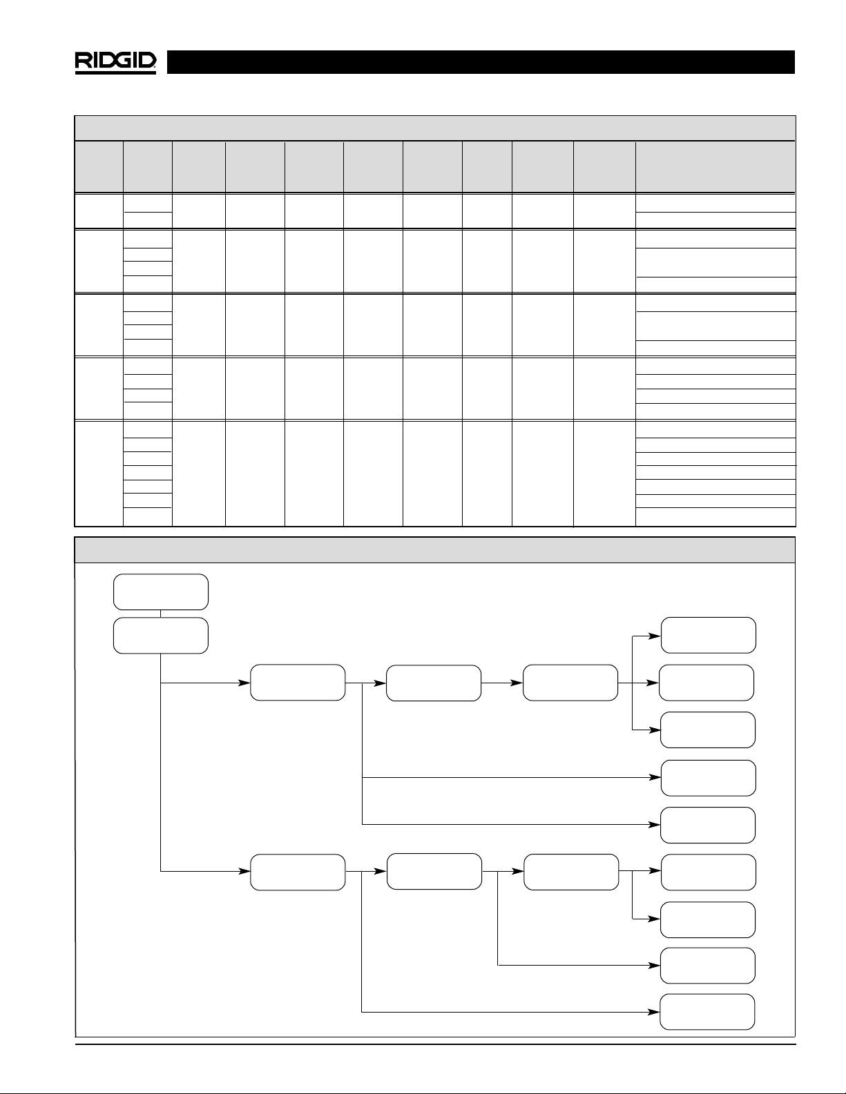
5. Assemble the tool for use and determine the feasibility
of the tapping operation. This is to confirm whether
the planned configuration will allow enough stroke to
complete the tap or if the configuration could allow the
over-penetration of the far side of the pipe. Select the
correct valve adapter, pilot drill, extension, and saw
adapter from the following Valve Adapter Selection
chart. The Flow Chart will assist the operator in determining the required equipment to perform the tap.
RT3422 Tapping Tool
Ridge Tool Company4
Page 5
RT3422 Tapping Tool
Ridge Tool Company 5
Valve Adapter Selection
Valve Bore CTS NPT NPT BSPT BSPT Pilot Saw Remarks
Size Size Adapter Female Male Female Male Size Extension Adapter
Adapter Adapter Adapter Adapter
3/4″ 0.625 76057 76087 76132 76177 76222 0.250 76047 76037
Preferred Configuration
0.688
1″ 0.750 76067 76092 76137 76182 76227 0.250 76047 76037
0.813
0.875 Preferred Configuration
0.938
1-1/4″ 1.000 76072 76097 76142 76187 76232 0.250 76047 76037
1.063
1.125 Preferred Configuration
1.188
1-1/2″ 1.250 76077 76102 76147 76192 76237 0.375 76052 — Special Saw Adapter
1.313 Special Saw Adapter
1.375 76042 Preferred Configuration
1.438
2″ 1.500 76082 76107 76152 76197 76242 0.375 76052 76042
1.563
1.625
1.688
1.750 Preferred Configuration
1.813
1.875
RT3422
MACHINE
PROPER SIZED COMMERCIAL
VALVE ADAPTER SMALL
NPT OR CTS FLARED HOLE SAWS
76047 76027 76037 SMALL
SMALL SMALL SMALL HOLE STEEL SHELL
3/4″ – 1″ TAPS EXTENSION PILOT DRILL SAW ADAPTER CUTTERS
76302
1-1/8″ CI/DI
CUTTER
SMALL
CI//DI
DRILLS
SMALL PVC
CUTTERS
76052 76032 76042 COMMERCIAL
LARGE LARGE LARGE HOLE LARGE
1-1/4″ – 2″ TAPS EXTENSION PILOT DRILL SAW ADAPTER HOLE SAWS
LARGE
STEEL SHELL
CUTTERS
LARGE CI/DI
CUTTERS
LARGE PVC
CUTTERS
Tapping Tool Assembly Flow Chart
Page 6
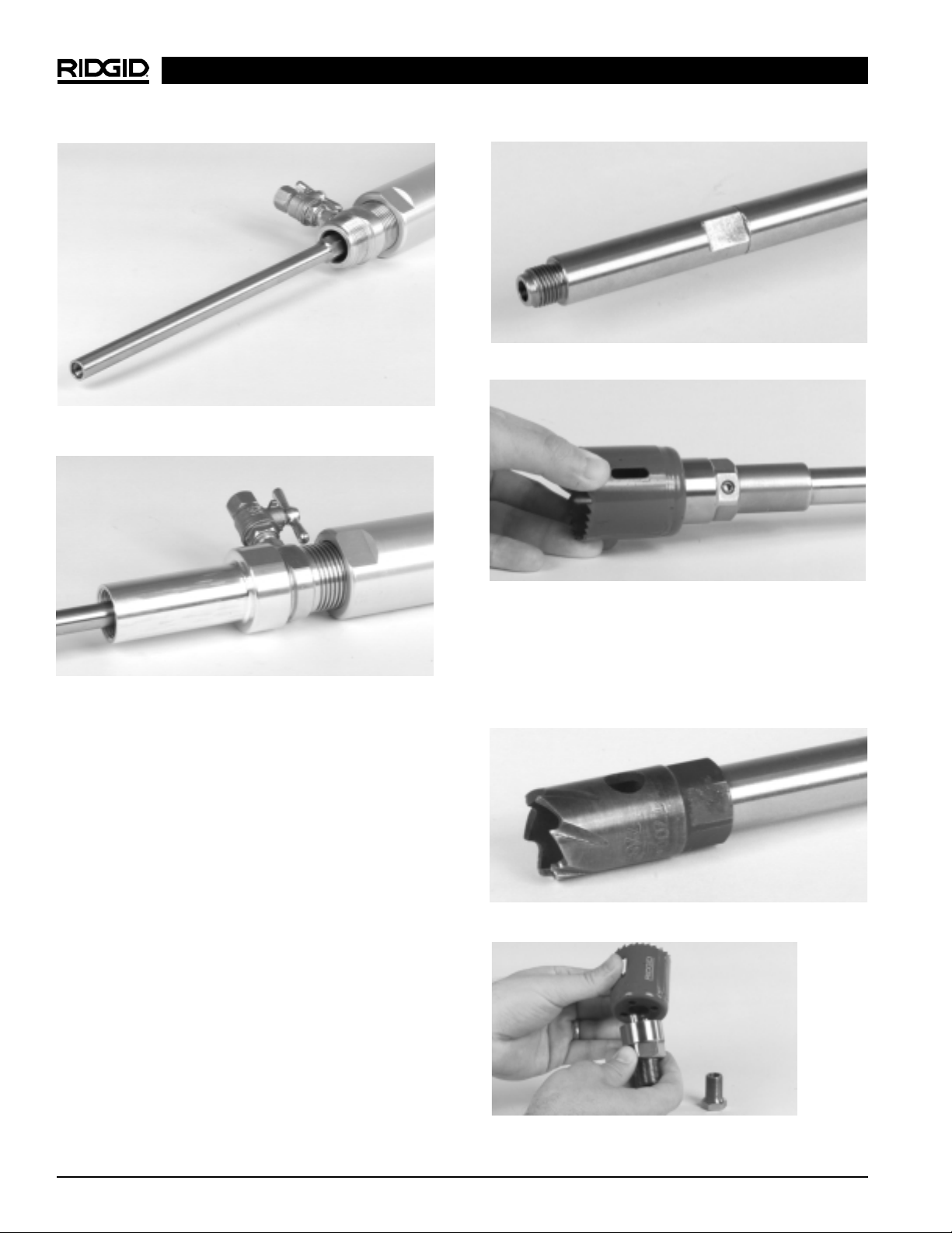
Figure 1 – Installation of extension
Figure 2 – Installation of valve adapter
a) Having ensured that the tool is in the shortest, col-
lapsed, position and having selected the proper size
extension, hold the spindle by the flats at the end and
screw the extension into the end of the spindle. This
only has to be hand tight as the threads will be tightened by the operation of the tool (Figure 1).
b) Inspect the “o-ring” seal in the valve adapter (replace
if damaged) and holding the bronze feed screw by the
flats, assemble the valve adapter onto the bronze
feed screw. This should be done by hand as the operator will feel first the seal engaging and then feel the
adapter reach an abrupt stop as the bronze feed
screw “bottoms out” in the valve adapter (Figure 2).
c) Select the cutter to be used for this particular opera-
tion from the chart on the next page. Note that the pilot
drill and hole saw adapter may not be required depending on the actual cutter selected. If the selected
cutter requires a hole saw adapter, screw it into the
end of the extension. CI/DI and PVC cutters do not require use of hole saw arbor. As before, this only has
to be hand tight (Figures 3 and 3a).
RT3422 Tapping Tool
Ridge Tool Company6
Figure 3 – Installation of small hole saw adapter
Figure 3a – Installation of large hole saw adapter
d) Inspect the selected cutter to be used for this partic-
ular operation to ensure that it is in good working
order and screw it into the hole saw arbor if present or
directly into the extension as required. As before,
this only has to be hand tight (Figures 4 and 4a).
Figure 4 – Installation of cutter on small hole saw arbor
Figure 4a – Installation of cutter on large hole saw arbor
Page 7
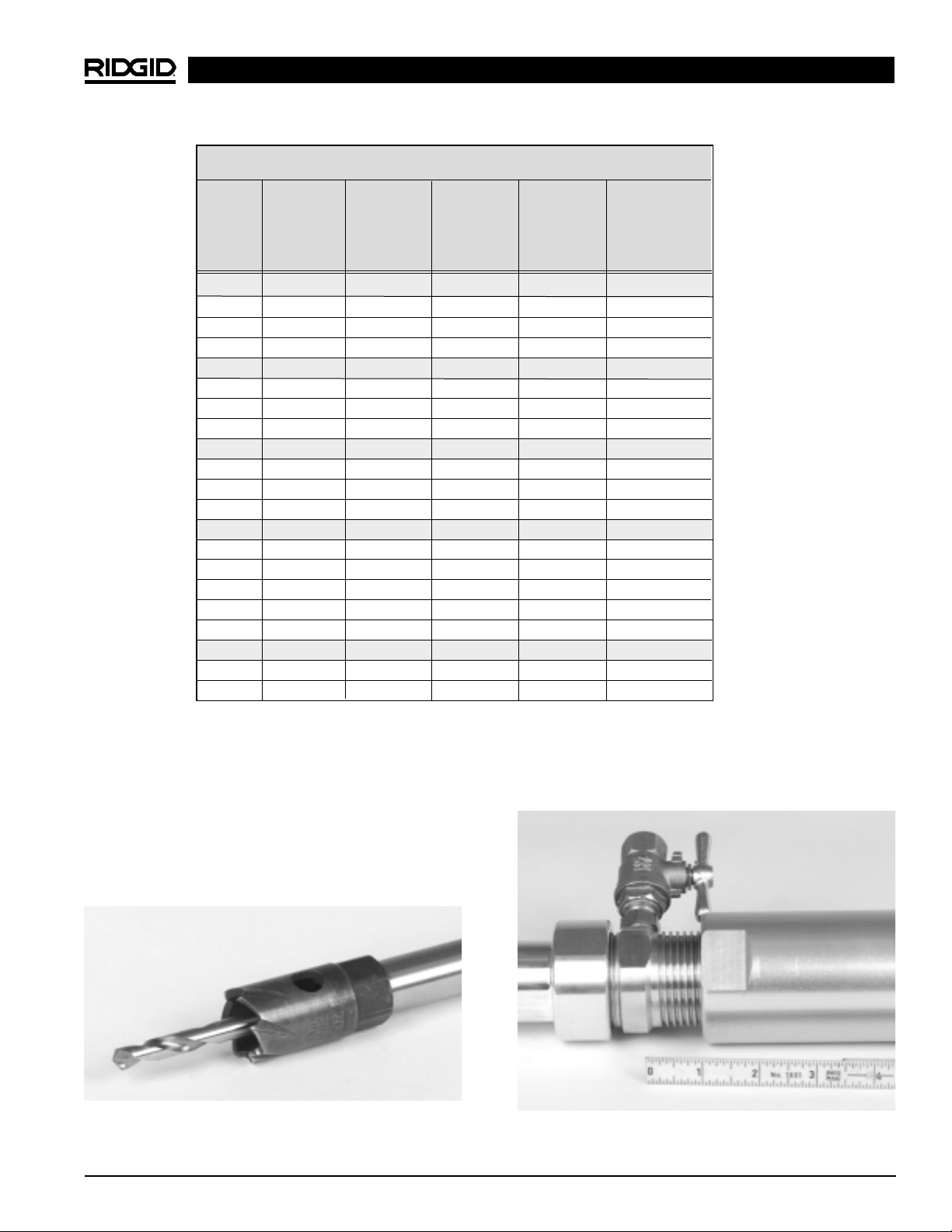
RIDGID Tapping Tool Cutter Selection Chart
Bore Fractional Ridgid RIDGID RIDGID RIDGID
Size Size Bi-Metal Steel CI/DI Cutters PVC Cutters
(Power (Manual (Power or Man- (Manual
Operation Operation Operation Operation
Only) Only) Only) Only)
0.625 5/8 R10 76267 76292 76317
0.688 11/16 R11
0.750 3/4 R12
0.813 13/16 R13
0.875 7/8 R14 76272 76297 76322
0.938 15/16 R15
1.000 1 R16
1.063 1-1/16 R17
1.125 1-1/8 R18 76277 76302 76327
1.188 1-3/16 R19
1.250 1-1/4 R20
1.313 1-5/16 R21
1.375 1-3/8 R22 76282 76307 76332
1.438 1-7/16 R23
1.500 1-1/2 R24
1.563 1-9/16 R25
1.625 1-5/8 R26
1.688 1-11/16 R27
1.750 1-3/4 R28 76287 76312 76337
1.813 1-13/16 R29
1.875 1-7/8 R30
RT3422 Tapping Tool
Ridge Tool Company 7
e) Inspect the selected pilot drill for this particular oper-
ation to ensure that it is in good working order. Pay
particular attention to the coupon retaining device
as coupon may not be retrieved if this device is damaged. Insert this pilot drill into the hole saw adapter if
present or directly into the cutter as required. Secure
the pilot drill in place with the set screw positioned on
the flat of the pilot and firmly tighten (Figure 5).
Figure 5 – Installation of pilot drill
f) Measure the distance from a point such as the wrench
flats on the feed screw to the end of the sleeve. In
Figure 6 below it is 1″.
Figure 6 – Measuring 1″ offset
Page 8
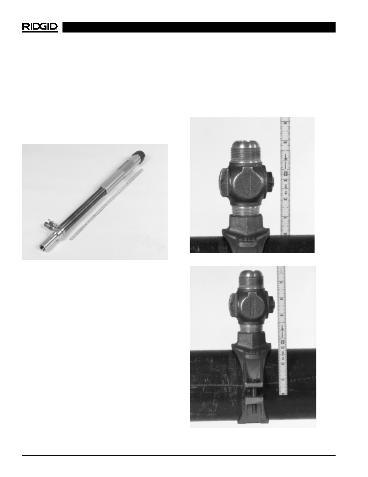
g) Unscrew the sleeve back up the bronze feed screw.
(i.e. Looking along the length of the tool from cap end
towards the drill end, the sleeve turns counter-clockwise to extend the tool). Turn the sleeve all the way
until it stops. Again measure the distance from a
point such as the wrench flats on the feed screw to
the end of the sleeve. In Figure 7 it is 15″. Subtract
the distance from the previous step (h) from this distance. The result is 14″ full stroke. Note that the
stroke distance may be affected by various valve
adapter / cutter combinations. Record the stroke in the
worksheet provided on page 13.
Figure 7 – Measuring full stoke distance
h) Attach the selected service saddle to the main in
accordance with the manufacturer’s specifications, or
weld the selected threadolet or weldolet to the main
in accordance with all applicable welding standards.
i) Apply pipe sealant to the threads on the “corporation
stop” or valve and tightly thread it into the saddle or
Thread-O-Let™ to assure a leak proof assembly.
Ensure that the valve is in the CLOSED position.
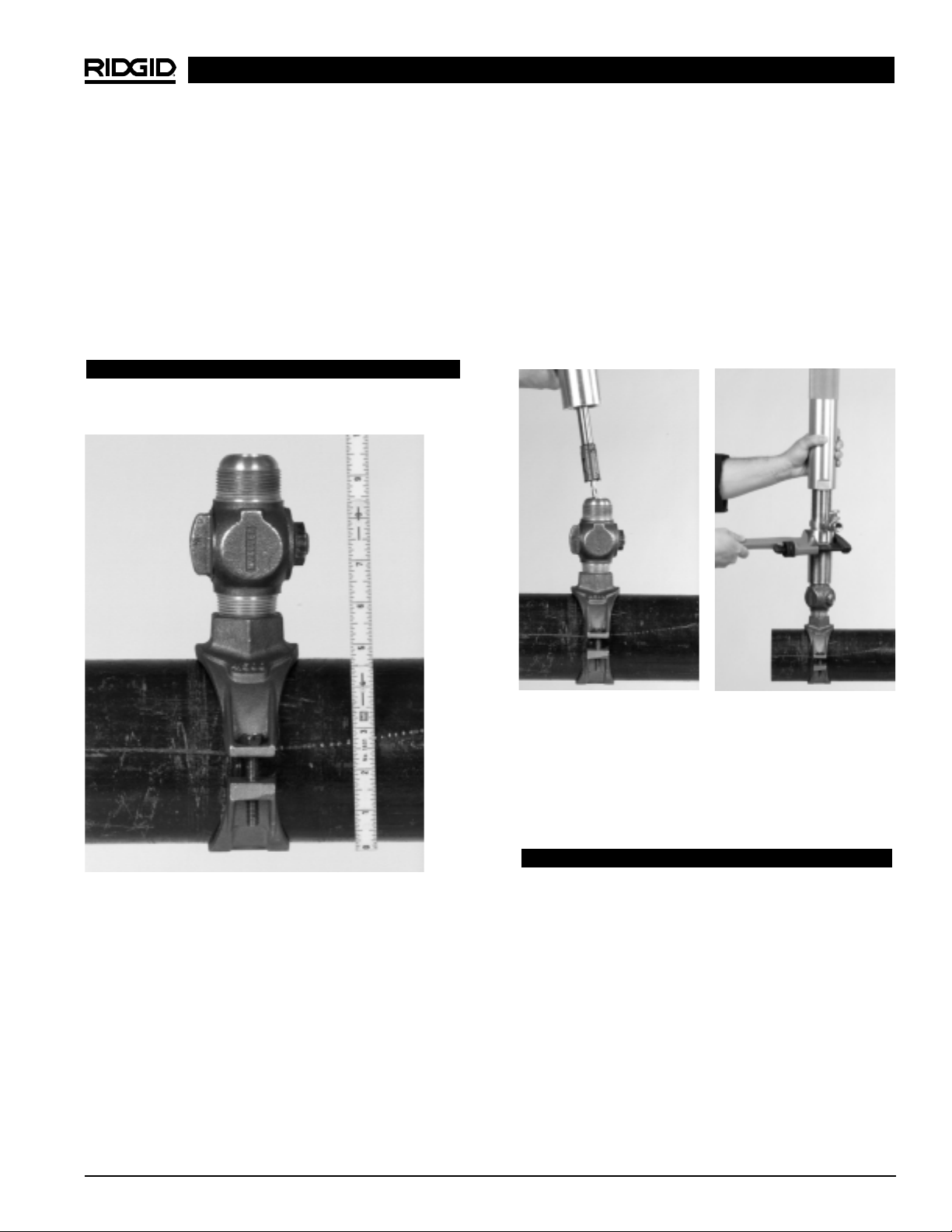
j) Measure the distance from the surface of the pipe to
the outlet end of the valve as shown in Figure 8 & 9.
This is the minimum amount of stroke required before
the cutter makes contact with the pipe to be drilled
into. (In the illustrated example this is 41/2″.) Record
this dimension in the worksheet provided. If this distance is within 1 inch of the stroke distance from
step (g) then the machine may not have enough
travel to safely complete the tap and this operation
must be aborted and reconfigured for a different
valve and/or saddle.
k) Measure the distance from the far surface of the
pipe to the outlet end of the valve as shown in Figure
10. This is the maximum amount of stroke required
before breaking through the far side of the pipe to be
drilled into. (In the illustrated example this is 10
1
/2″.)
Record this dimension in the worksheet provided. If
this distance is less than the stroke distance from step
(g) then the machine has enough travel to penetrate
the far side of the pipe. This is true in the illustrated
case. Therefore, this operation must be carefully executed to avoid problems.
Figure 8 – Measuring valve standoff distance
Figure 9 – Measuring valve standoff distance
RT3422 Tapping Tool
Ridge Tool Company8
Page 9
connection of the valve adapter to the valve when
using CTS (Copper Tube Size – flared or compression) adapters does not require pipe sealant but
must have the appropriate gasket in place and be in
good working condition.
3. Open, close and re-open the valve or the “corporation
stop”, this is to ensure that the pilot drill does not interfere with the operation of the valve. In the event of
interference in closing the valve, another valve must
be substituted and this whole procedure must be
re-started.
Figure 11 – Attaching tool to valve
4. If the bleed off valve is to be used, a hose may be
connected to it to help direct the discharge.
Remember to restrain the free end of the hose to
control the direction of the discharge. Note that this
discharge is the same as the media in the pipe.
WARNING!
Be sure no one is standing in line of the discharge
from the bleed valve in the event of accidental
opening of the valve. Pressures may be very high
and can result in serious injury.
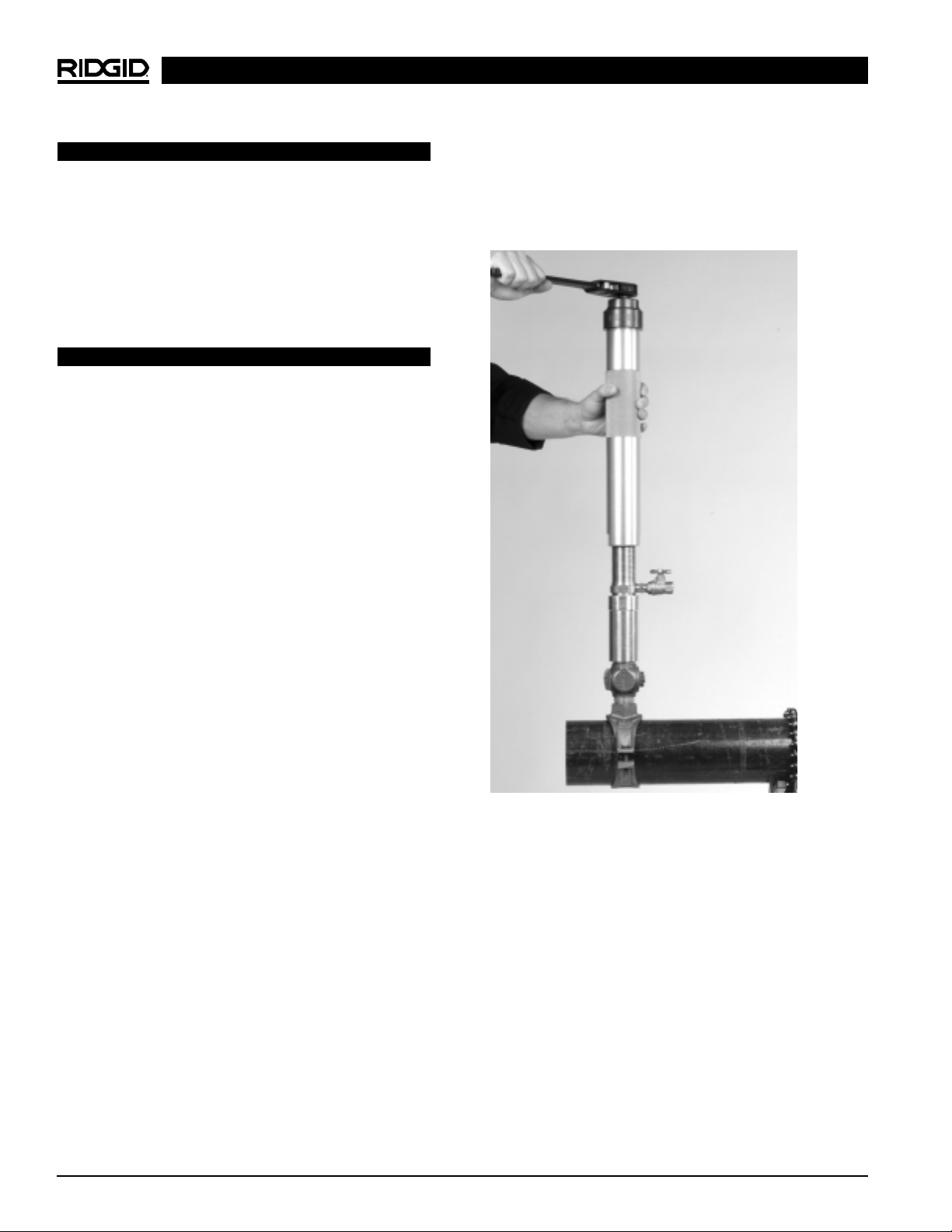
5. Turn the sleeve clockwise until the cutter comes into
light contact with the main, and back the sleeve up
one turn. Using the ratchet wrench, or a power
tool, rotate the drive shaft at the 11/16″ hex while
continually applying pressure by turning the sleeve.
Do not apply too much pressure on the cutter and
pipe with the feed screw. Gentle light pressure applied with the feed will produce superior cutting
characteristics (Figure 12).
l) Calculate the ideal distance to penetrate in order to
stop at the centerline of the pipe. Add the valve
standoff distance from step (j) to the maximum stroke
from step (k) and divide the result by 2. (In the example illustrated this is 10
1
/2″ plus 41/2″ which gives
15″, then divided by 2 yields 71/2″ ideal penetration.
m) Subtract the ideal penetration distance from the full
stroke in step (g). (In the example illustrated this is 14″
total stroke minus 71/2″ required stroke which equals
61/2″ remaining unusable stroke.)
WARNING
Improper measurements may result in tapping
through bottom of pipe.
Figure 10 – Measuring maximum stroke
Tapping into the Main
1. If the bleed valve assembly is not going to be used,
ensure that the bleed-off valve is closed or a 3/8″ plug
is installed. Use pipe sealant to seal the threads on
the bleed valve and plug.
2. Attach the fully assembled and fully extended tapping
tool to the outlet thread of the valve by screwing on
the valve adapter(Figure 11). Pipe sealant is required
for NPT and BSPT valve adapters in the temporary
assembly between the valve and the valve adapter
and it should be firmly tightened so as not to leak. The
RT3422 Tapping Tool
Ridge Tool Company 9
Page 10
WARNING!
Excessive feeding of the cutter may result in high
torque feedback to the operator and could wrench
or injure arm.
Continue to drill through the main until no resistance
is felt when advancing the feed. Stop immediately if
only the “remaining unusable stroke” remains to be
used. Continuing past this point could cause penetration through the far side of the pipe.
WARNING!
DO NOT tap through the bottom of the pipe.
6. The drilling into the pipe is now complete. The valve
and saddle as well as the tool are now filled with
the media in the pipe. Turn the sleeve counter-clockwise until all the threads of the bronze feed screw are
exposed and the sleeve comes to a halt. This action
has fully retracted the cutter and the coupon. Close
the corporation stop or valve. Should it be difficult to
close the valve (due to chips from the drilling operation), attach a hose to the bleed valve assembly if it is
not already there and open the bleed valve to “wash”
away as many chips as possible. Then rock the
valve open and closed until it can be completely
shut-off. It is vital that the valve is closed before proceeding. If the bleed valve assembly is in use it may
be closed as well and the hose removed. Note that
this hose will contain residue of the same media that
is in the pipe.
7. Remove the ratchet or power tool from the hex on the
drive shaft. Place a wrench on the valve to prevent it
from disconnecting as the valve adapter is unscrewed
from the valve with another wrench. Be prepared
for the tool to suddenly come free and for it to spill out
any media it contains. If the drilled pipe was dry, be
aware that the cutter may be hot.
8. The new plumbing may now be attached to the outlet end of the valve. After that, all that is required is to
open the valve to activate the newly installed system.
9. To remove the coupon from the cutter, turn the
sleeve clock-wise until the cutter is exposed. Shell cutters have a hole or slot to allow the coupon to be
pushed out. Remove the cutter if required, in order to
make coupon removal easier. If using a coupon retaining pilot bit, squeeze the spring retainer to allow
the coupon to slide off. After completing all taps of
this configuration, continue to step 10. If more taps
are needed, reinstall the cutter and start again from
step 1.
10. Remove the valve adapter, drill or cutter, pilot drill (if
used), saw adapter (if used) and extension from the
tool. Turn the sleeve clockwise until all the threads of
the bronze feed screw are hidden and the tool is
fully collapsed. Simply wipe all the components until
clean and dry and store them in the toolbox.
Figure 12 – Pivot of hand on ratchet and other hand on
tool
Maintenance
Cleaning and Maintaining the RT3422
This procedure should only be conducted by a qualified
service technician.
Tool Disassembly Procedure
1. Turn the sleeve clockwise until all the threads of the
bronze feed screw are hidden and the tool is fully collapsed. Place the tool horizontally on a table so parts
do not fall out.
2. Locate and remove the setscrew from the side of
the red cap.
RT3422 Tapping Tool
Ridge Tool Company10
Page 11

RT3422 Tapping Tool
Ridge Tool Company 11
3. Locate and remove the retaining ring and washer
from the end of the red cap.
4. Unscrew and remove the red end cap. Note that
any media that has escaped the seal will collect
under this cap and may be spilled at this time. Do not
remove the “maintenance free” sealed bearing from
the end cap unless bearing replacement is intended.
If the bearing must be removed use two 7/64″ diameter pins of equal length to slowly press the bearing
out. Using a hammer to do this will damage the precision recess in the end cap for the bearing.
5. Locate the seal cap and remove the two locking setscrews and then unscrew and remove the seal cap
itself. Remove the seal ring from inside the end of the
bronze feed screw just exposed. Remove the two
graphite seals from the same place. If the graphite
seals are damaged or worn discard them and replace two new seals. Typically, seals should be
replaced after every 20 taps or every 6 months,
whichever comes first.
6. Push the spindle from the hex end and remove it from
the opposite end of the tool. Turn the sleeve counterclockwise until all the threads of the bronze feed
screw are exposed and the sleeve separates from the
bronze feed screw. This completes the disassembly
of the tool.
Part Cleaning Procedure
1. Wash the parts in a degreaser tank and wipe each individual part until clean and dry.
2. Seals cannot be washed and reused.
3. Be careful not to wash parts with materials that will
corrode or degrade the parts in any way.
Tool Assembly Procedure
1. Inspect the bronze feed screw and sleeve for any
damage, replace if required. Lubricate the acme
threads on the bronze feed screw with grease. Turn
the sleeve clockwise onto the bronze feed screw
until all the threads are hidden and the tool is fully collapsed. Place the tool horizontally on a table so parts
do not fall out.
2. Inspect the spindle for any damage and replace if required. Insert the spindle into the adapter end of the
bronze feed screw hex end first. Slide it in as far as it
will go.
3. Use the original seals if they are undamaged, not
worn, and uncontaminated otherwise replace them.
Insert two graphite seals into the pocket at the cap
end of the bronze feed screw so that the seals surround the spindle shaft. Place them in the pocket with
the butt joints staggered 180° (to avoid a weak spot in
the seal).
4. Inspect the seal ring for any damage and replace if required. Place the seal ring on top of the seals with the
angled face in contact with the seals and the reduced diameter on the ring facing the hex end of
the spindle.
5. Inspect the seal cap for any damage and replace if required. Screw the seal cap partially onto the bronze
feed screw. Loosely screw the two locking set-screws
into the seal cap.
6. Adjust the seal pressure by progressively tightening the seal cap with a wrench as the effort to turn the
spindle with a second wrench is tested. When resistance to turning the spindle is felt, loosen the seal nut
just enough to remove most resistance. Lock the
seal nut in place with the two locking set-screws.
7. Inspect the end cap / bearing assembly for any damage and replace if required. Place the end cap/bearing assembly on the protruding spindle shaft, followed by the washer and secure in place with the
retaining ring. Push the spindle / end cap assembly
onto the sleeve and screw into position. To prevent
the end cap from being accidentally unscrewed secure it in place with the set-screw into the side of the
end cap.
8. Wipe the tool down to remove excess lubricant and
return the tool to the box ready for the next use.
Page 12

RT3422 Tapping Tool
Ridge Tool Company12
Service and Repair
The above section
will take care of most of the service needs of this tool
with the exception of main bearing replacement. Any
problems not addressed by the “Cleaning and
Maintaining this Tool” section or replacement of this
bearing should only be handled by an authorized
RIDGID service technician.
If any maintenance is required other than that outlined, the
tool should be sent to a RIDGID Independent Authorized
Center or returned to the factory. All repairs made by
Ridge service facilities are warranted against defects in
material and workmanship.
“Cleaning and Maintaining this Tool”
Page 13
RT3422 Tapping Tool
Ridge Tool Company 13
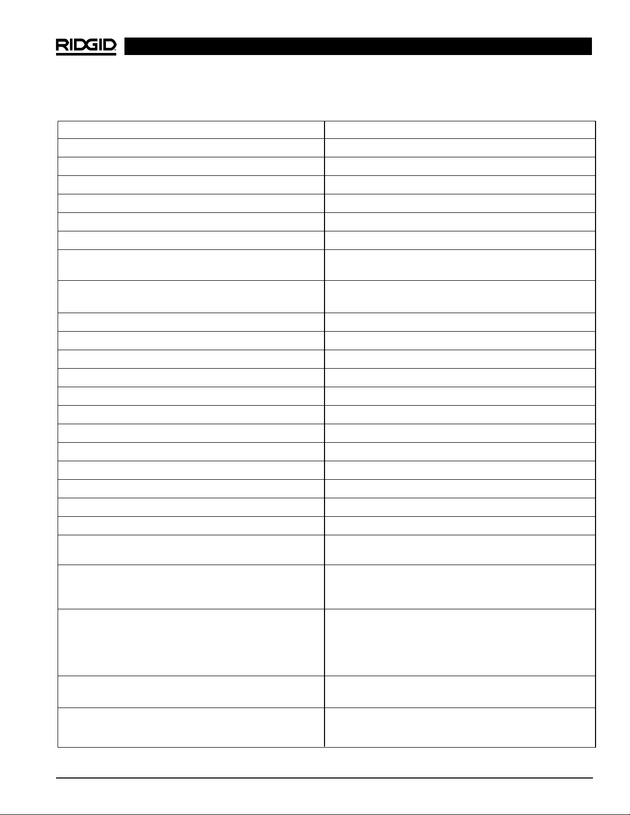
Worksheet
Pipe Identification Code Marking
Media
Pressure
Actual Pipe Type and Size
Identified By
Saddle or Thread-O-Let™ Manufacturer
Part Number
Designed Saddle Pipe Type & Size
(Must match pipe data above)
Designed Saddle or Threadolet Pressure Rating
(Must exceed main pressure)
Outlet Size
Installed / Welded Date
Installed / Welded By
Inspected Date
Saddle or Thread-O-Let™ Installation Approved By
Valve Manufacturer
Part Number
Valve Type & Size
Valve Pressure Rating (Must exceed main pressure)
Valve Approved By
Datum Offset (see Figure 6)
Datum to Full Stroke (see Figure 7)
Subtract “Datum Offset” from “Datum to Full Stroke” for
“Full Stroke Distance”
Valve Standoff Distance (see Figures 8 & 9) (Note if Full
Stroke Distance – 1″ = Valve Standoff Distance then
ABORT THIS TAP!)
Maximum Stroke (photo 10) (Note if Maximum Stroke is
less than Full Stroke Distance be warned that penetration
of the back of the pipe is possible! Observe Unusable
Stroke Remainder (see Figure 12) to execute this tap
safely!)
Add Valve Standoff Distance to Maximum Stroke then divide result by 2 for Ideal Penetration Distance
Subtract Ideal Penetration Distance from Full Stroke
Distance for Unusable Stroke Remainder. (Figure 12)
Page 14

What is covered
RIDGID
®
tools are warranted to be free of defects in workmanship and material.
How long coverage lasts
This warranty lasts for the lifetime of the RIDGID
®
tool. Warranty coverage ends when the prod-
uct becomes unusable for reasons other than defects in workmanship or material.
How you can get service
To obtain the benefit of this warranty, deliver via prepaid transportation the complete product
to RIDGE TOOL COMPANY, Elyria, Ohio, or any authorized RIDGID
®
INDEPENDENT SERVICE
CENTER. Pipe wrenches and other hand tools should be returned to the place of purchase.
What we will do to correct problems
Warranted products will be repaired or replaced, at RIDGE TOOL’S option, and returned at no
charge; or, if after three attempts to repair or replace during the warranty period the product
is still defective, you can elect to receive a full refund of your purchase price.
What is not covered
Failures due to misuse, abuse or normal wear and tear are not covered by this warranty. RIDGE
TOOL shall not be responsible for any incidental or consequential damages.
How local law relates to the warranty
Some states do not allow the exclusion or limitation of incidental or consequential damages,
so the above limitation or exclusion may not apply to you. This warranty gives you specific
rights, and you may also have other rights, which vary, from state to state, province to
province, or country to country.
No other express warranty applies
This FULL LIFETIME WARRANTY is the sole and exclusive warranty for RIDGID
®
products. No
employee, agent, dealer, or other person is authorized to alter this warranty or make any other
warranty on behalf of the RIDGE TOOL COMPANY.
FULL LIFETIME
Printed in U.S.A. 6/99 059-500-101.10
WARRANTY
Against Material Defects
& Workmanship
99 Washington Street
Melrose, MA 02176
Phone 781-665-1400
Toll Free 1-800-517-8431
Visit us at www.TestEquipmentDepot.com
 Loading...