

Page 1
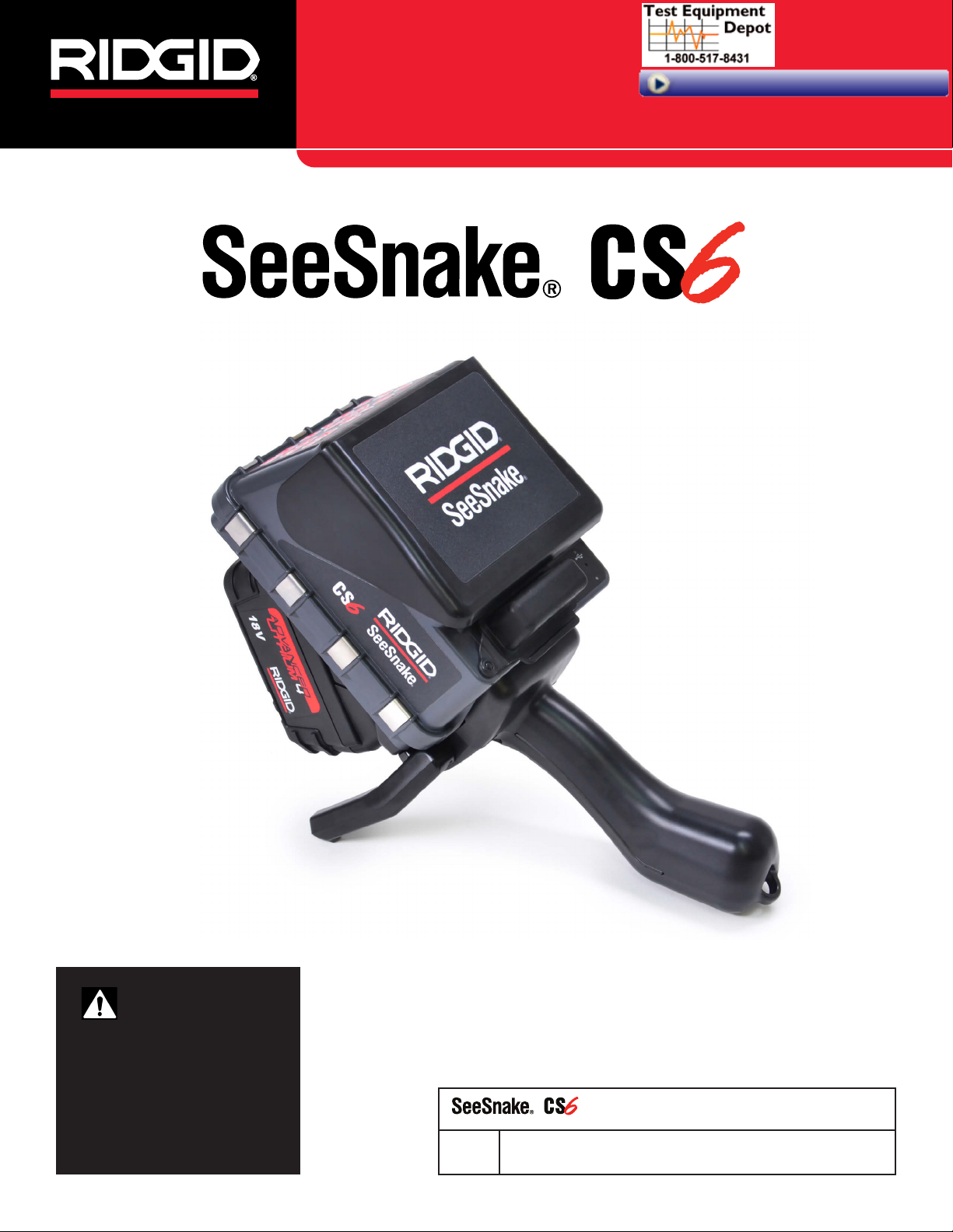
Operator’s Manual
99 Washington Street
Melrose, MA 02176
Phone 781-665-1400
Toll Free 1-800-517-8431
Visit us at www.TestEquipmentDepot.com
WARNING!
Read this manual carefully before using this tool.
Failure to understand and
follow the contents of this
manual may result in electrical shock, fire, and/or serious injury.
Serial
No.
Original Instructions – English – 1
Page 2

Table of Contents
Introduction
Regulatory Statements ...............................................................................................................................................4
Safety Symbols ...........................................................................................................................................................4
General Safety Rules
Work Area Safety ........................................................................................................................................................ 5
Electrical Safety .......................................................................................................................................................... 5
Personal Safety ..........................................................................................................................................................5
Equipment Use and Care ...........................................................................................................................................6
Battery Use and Care .................................................................................................................................................6
Pre-Operation Inspection
Specific Safety Information
See Snake CS6 Safety ...............................................................................................................................................7
Product Overview
Description .................................................................................................................................................................8
Specifications .............................................................................................................................................................9
Standard Equipment ................................................................................................................................................... 9
System Components .................................................................................................................................................. 9
Keypad Overview...................................................................................................................................................... 11
Operating Instructions
Placement ................................................................................................................................................................ 13
Connecting to a Camera Reel .................................................................................................................................. 13
Powering the CS6 ..................................................................................................................................................... 14
Integrated Counter .................................................................................................................................................... 15
Inspection Overview
Capturing Media ....................................................................................................................................................... 16
Interface Icons .......................................................................................................................................................... 16
Custom Overlay ........................................................................................................................................................ 18
Locating the Sonde ..................................................................................................................................................20
Line Tracing the Push Cable .....................................................................................................................................21
Job Review ............................................................................................................................................................... 22
Managing Jobs
Job List ..................................................................................................................................................................... 25
USB Options .............................................................................................................................................................26
Job Settings ..............................................................................................................................................................27
System Settings
Overlay Details .........................................................................................................................................................28
Restoring System Settings........................................................................................................................................28
Delivering Reports .................................................................................................................................................... 28
2 – English – CS6
Page 3

Software
HQ Software .............................................................................................................................................................29
Updating CS6 Software ............................................................................................................................................30
Maintenance and Support
Cleaning ...................................................................................................................................................................31
Accessories .............................................................................................................................................................. 31
Transport and Storage .............................................................................................................................................. 31
Service and Repair ................................................................................................................................................... 32
Disposal ....................................................................................................................................................................32
Battery Disposal .......................................................................................................................................................32
Troubleshooting ........................................................................................................................................................33
CS6 – English – 3
Page 4
Introduction
The warnings, cautions, and instructions discussed in this manual cannot cover all possi-
ble conditions and situations that may occur. It
must be understood by the operator that common sense and caution are factors which cannot
be built into this product, but must be supplied
by the operator.
Safety Symbols
In this manual and on the product, safety symbols and
signal words are used to communicate important safety
information. This section is provided to improve understanding of these signal words and symbols.
This is the safety alert symbol. It is used to alert
you to potential personal injury hazards. Obey all
safety messages that follow this symbol to avoid
possible injury or death.
Regulatory Statements
The EC Declaration of Conformity (890-011-
320.10) will accompany this manual as a separate booklet when required.
This device complies with Part 15 of FCC rules.
Operation is subject to the following two conditions: (1) This device may not cause harmful interference, and (2) this device must accept any
interference received, including interference that
may cause undesired operation.
DANGER
DANGER indicates a hazardous situation which, if not
avoided, will result in death or serious injury.
WARNING
WARNING indicates a hazardous situation which, if not
avoided, could result in death or serious injury.
CAUTION
CAUTION indicates a hazardous situation which, if not
avoided, could result in minor or moderate injury.
NOTICE
NOTICE indicates information that relates
to the protection of property.
This symbol means read the manual carefully
before using the equipment. The manual contains important information on the safe and
proper operation of the equipment.
This symbol means always wear safety glasses
with side shields or goggles when handling or
using this equipment to reduce the risk of eye injury.
This symbol indicates the risk of electrical shock.
4 – English – CS6
Page 5

General Safety Rules
WARNING
Read all safety warnings and instructions. Failure to
follow the warnings and instructions may result in
electrical shock, fire, and/or serious injury.
SAVE THESE INSTRUCTIONS!
Work Area Safety
• Keep your work area clean and well lit. Cluttered or
dark areas invite accidents.
• Do not operate equipment in explosive atmo-
spheres, such as in the presence of flammable liquids, gases, or dust. Equipment can create sparks
which may ignite the dust or fumes.
• Keep children and bystanders away while operat-
ing equipment. Distractions can cause you to lose
control.
Personal Safety
• Stay alert, watch what you are doing, and use common sense when operating equipment. Do not use
equipment while you are tired or under the influence of
drugs, alcohol, or medication. A moment of inattention
while operating equipment may result in serious injury.
• Dress properly. Do not wear loose clothing or jewelry.
Loose clothes, jewelry, and long hair can be caught in
moving parts.
• Practice good hygiene. Use hot, soapy water to wash
hands and other body parts exposed to drain contents
after handling or using drain inspection equipment. To
prevent contamination from toxic or infectious material, do not eat or smoke while operating or handling
drain inspection equipment.
• Always use appropriate personal protective equip-
ment when handling and using equipment in
drains. Drains may contain chemicals, bacteria, and
other substances that may be toxic, infectious, and
cause burns or other issues. Appropriate personal protective equipment always includes safety glasses and
may include a dust mask, hard hat, hearing protection,
drain cleaning gloves or mitts, latex or rubber gloves,
face shields, goggles, protective clothing, respirators,
and steel toed, non-skid footwear.
• Avoid traffic. Pay attention to moving vehicles when
using on or near roadways. Wear high-visibility clothing or reflector vests.
Electrical Safety
• Avoid body contact with earthed or grounded surfaces such as pipes, radiators, ranges, and refrigerators. There is an increased risk of electrical shock
if your body is earthed or grounded.
• Do not expose equipment to rain or wet condi-
tions. Water entering equipment will increase the risk
of electrical shock.
• Keep all electrical connections dry and off the
ground. Touching equipment or plugs with wet hands
can increase the risk of electrical shock.
• Do not abuse the cord. Never use the cord for car-
rying, pulling, or unplugging the power tool. Keep cord
away from heat, oil, sharp edges, and moving parts.
Damaged or entangled cords increase the risk of electrical shock.
• If operating equipment in a damp location is un-
avoidable, use a ground fault circuit interrupter
(GFCI) protected supply. Use of a GFCI reduces the
risk of electrical shock.
• If using drain cleaning equipment and drain in-
spection equipment at the same time, wear RIDGID
drain cleaning gloves. Never grasp the rotating drain
cleaning cable with anything else, including other
gloves or a rag which can become wrapped around
the cable and cause hand injuries. Only wear latex
or rubber gloves underneath RIDGID drain cleaner
gloves. Do not use damaged drain cleaning gloves.
CS6 – English – 5
Page 6

Equipment Use and Care
• Do not force equipment. Use the correct equipment
for your application. The correct equipment does the
job better and more safely.
Battery Use and Care
• Use equipment only with specifically designed
battery packs. Use of any other battery packs may
create a risk of injury and/or fire.
• Do not use equipment if the power switch does not
turn it on and off. Any equipment that cannot be controlled with the power switch is dangerous and must
be repaired.
• Disconnect the plug from the power source and/or
the battery pack from the equipment before making adjustments, changing accessories, or storing.
Preventive safety measures reduce the risk of injury.
• Store idle equipment out of the reach of children
and do not allow persons unfamiliar with the equipment or these instructions to operate the equipment. Equipment can be dangerous in the hands of
untrained users.
• Maintain equipment. Check for misalignment or bind-
ing of moving parts, missing parts, breakage of parts,
and any other condition that may affect the equipment’s operation. If damaged, have the equipment
repaired before use. Many accidents are caused by
poorly maintained equipment.
• Do not overreach. Keep proper footing and balance
at all times. This enables better control of the equipment in unexpected situations.
• Use the equipment and accessories in accordance
with these instructions; taking into account the
working conditions and the work to be performed.
Use of the equipment for operations different from
those intended can result in a hazardous situation.
• Use only accessories that are recommended by
the manufacturer for your equipment. Accessories
that may be suitable for one piece of equipment may
become hazardous when used with other equipment.
• Recharge only with the charger specified by the
manufacturer. A charger suitable for one type of battery pack may create a risk of fire when used with another battery pack.
• Do not cover charger while in use. Proper ventila-
tion is required for correct operation. Covering charger
in use could result in fire.
• Use and store batteries and chargers in dry, ap-
propriate temperature areas according to their
documentation. Extreme temperatures and moisture
can damage batteries and result in leakage, electrical
shock, fire or burns.
• Do not probe the battery with conductive objects.
Shorting of battery terminals may cause sparks, burns,
or electrical shock. When the battery pack is not in use,
keep it away from other metal objects, like paper clips,
coins, keys, nails, screws or any other small metal object that can make a connection from one terminal to
the other. Shorting the battery terminals may cause
burns or a fire.
• Under abusive conditions, liquid may eject from
battery; avoid contact. If contact occurs, flush with
water. If liquid contacts eyes, seek medical help. Liquid
ejected from the battery may cause irritation or burns.
• Properly dispose of batteries. Exposure to high tem-
peratures can cause the batteries to explode; do not
dispose of in a fire. Some countries have regulations
concerning battery disposal. Follow all applicable regulations.
• Keep handles dry, clean, and free from oil and
grease. Clean handles give better control of the equipment.
6 – English – CS6
Page 7
Pre-Operation Inspection
Specic Safety Information
WARNING
To reduce the risk of serious injury from electrical
shock or other causes, and to prevent damage to
your equipment, inspect all equipment and correct
any problems before each use.
To inspect all equipment, follow these steps:
1. Power off your equipment.
2. Disconnect and inspect all cords, cables, and connectors for damage or modification.
3. Clean any dirt, oil, or other contamination from your
equipment to ease inspection and to prevent it from
slipping from your grip during transportation or use.
4. Inspect your equipment for any broken, worn, missing, misaligned, or binding parts, or any other condition which might prevent safe, normal operation.
5. Refer to the instructions for all other equipment to
inspect and make sure it is in good, usable condition.
6. Check your work area for the following:
• Adequate lighting.
• The presence of flammable liquids, vapors, or
dust that may ignite. If present, do not work in
area until sources have been identified and corrected. The equipment is not explosion proof.
Electrical connections can cause sparks.
• A clear, level, stable, and dry place for the operator. Do not use the equipment while standing
in water.
7. Examine the job to be done and determine the correct equipment for the task.
8. Observe the work area and erect barriers as necessary to keep bystanders away.
WARNING
This section contains important safety information
that is specific to the See Snake CS6. Read these precautions carefully before using the CS6 to reduce
the risk of electrical shock, fire, and/or serious injury.
SAVE ALL WARNINGS AND INSTRUCTIONS
FOR FUTURE REFERENCE!
See Snake CS6 Safety
• Read and understand this manual, the camera reel
manual, and the instructions for any other equipment you are using before operating the equipment. Failure to follow all instructions may result in
property damage and/or serious injury. Keep this manual with the equipment for future use.
• Operating the equipment while in water increases
the risk of electrical shock. Do not operate the CS6
if the operator or equipment are standing in water.
• The CS6’s battery and other electrical equipment
and connections are not waterproof. Do not expose
the equipment to wet locations.
• The CS6 is not designed to provide high voltage
protection and isolation. Do not use where a danger
of high voltage contact is present.
• Only power the CS6 with a compatible battery or a
double insulated AC adapter. The AC adapter is intended for indoor use only. When powered by a battery,
protect the CS6 from exposure to weather.
• Do not expose the CS6 to mechanical shocks. Ex-
posure to mechanical shocks can damage equipment
and increases the risk of serious injury.
CS6 – English – 7
Page 8
Product Overview
Description
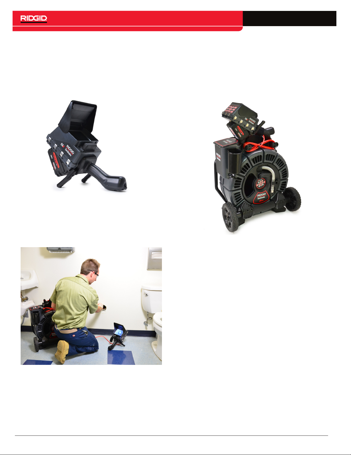
The See Snake CS6 is a compact, portable digital reporting monitor which you can use as a simple monitor or,
when a USB drive is inserted, an advanced recording
monitor with built-in reporting capabilities.
With the CS6 you’ll be able to deliver a USB drive containing a professional, automatically generated report of
the inspection to your customer. Having this capability
built into the CS6 means you can deliver impressive reports without loading media and editing jobs as a secondary step.
While the CS6 can connect to any See Snake camera reel, it conveniently docks onto the See Snake Max
rM200 for ease of transport and storage. The CS6 is designed to dock onto the See Snake Max rM200, completing the See Snake Max rM200 Diagnostic System. A
complete See Snake Max Diagnostic System includes a
transport case, a drum with camera and push cable, and
a digital reporting monitor.
HQ is software that gives you the ability to manage jobs,
organize media and job information, and generate reports for customers.
The included 8GB USB drive comes with HQ preloaded.
Connect the USB drive to your computer to automatically install HQ and register your CS6. You can also install
HQ from the included disk or download the latest version
from www.hq.see snake.com.
8 – English – CS6
Page 9
Specifications
Weight 1.6 kg [3.6 lb]
Dimensions
Length 362 mm [14.2 in]
Width 165 mm [6.5 in]
Standard Equipment
• See Snake CS6
• AC Adapter
• 8 GB USB Drive (with HQ preloaded)
• Operator’s Manual
• Product Video
Height 128 mm [5 in]
18 V Li-Ion
Power Source
Power Rating 16-25 VDC, 25 W
Display
Type Color LCD
Size
Resolution
Brightness 500 Cd/m2
Media
Video
Autolog video
rechargeable battery
or optional AC adapter
115 mm × 86 mm
[4.5 in × 3.4 in]
VGA
640 × 480 pixels
MPEG4 (H.264)
30 FPS
MPEG4 (H.264)
Low, variable frame
rate for decreased file
size
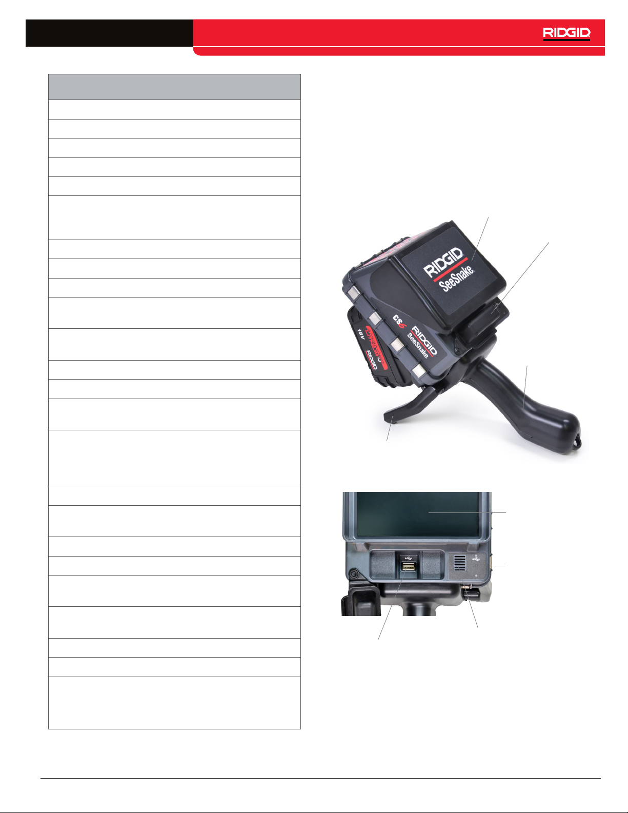
System Components
Front Cover
USB Port Cover
Handle
Kick Stand
Photos JPG
Audio
Transfer Method USB drive
Operating Environment
Temperature*
Storage temperature
Relative humidity 5 to 95 percent
Altitude 4,000 m [13,120 ft]
*The AC adapter is rated for 0°C to 40°C [32°F to
104°F]. When working in temperatures outside the
range of 0°C to 40°C [32°F to 104°F], do not use the
AC adapter.
Integrated microphone
and speaker
0°C to 40°C
[32°F to 104°F]
-10°C to 70°C
[14°F to 158°F]
LCD Display
Microphone
Speaker
USB Port
CS6 – English – 9
Page 10
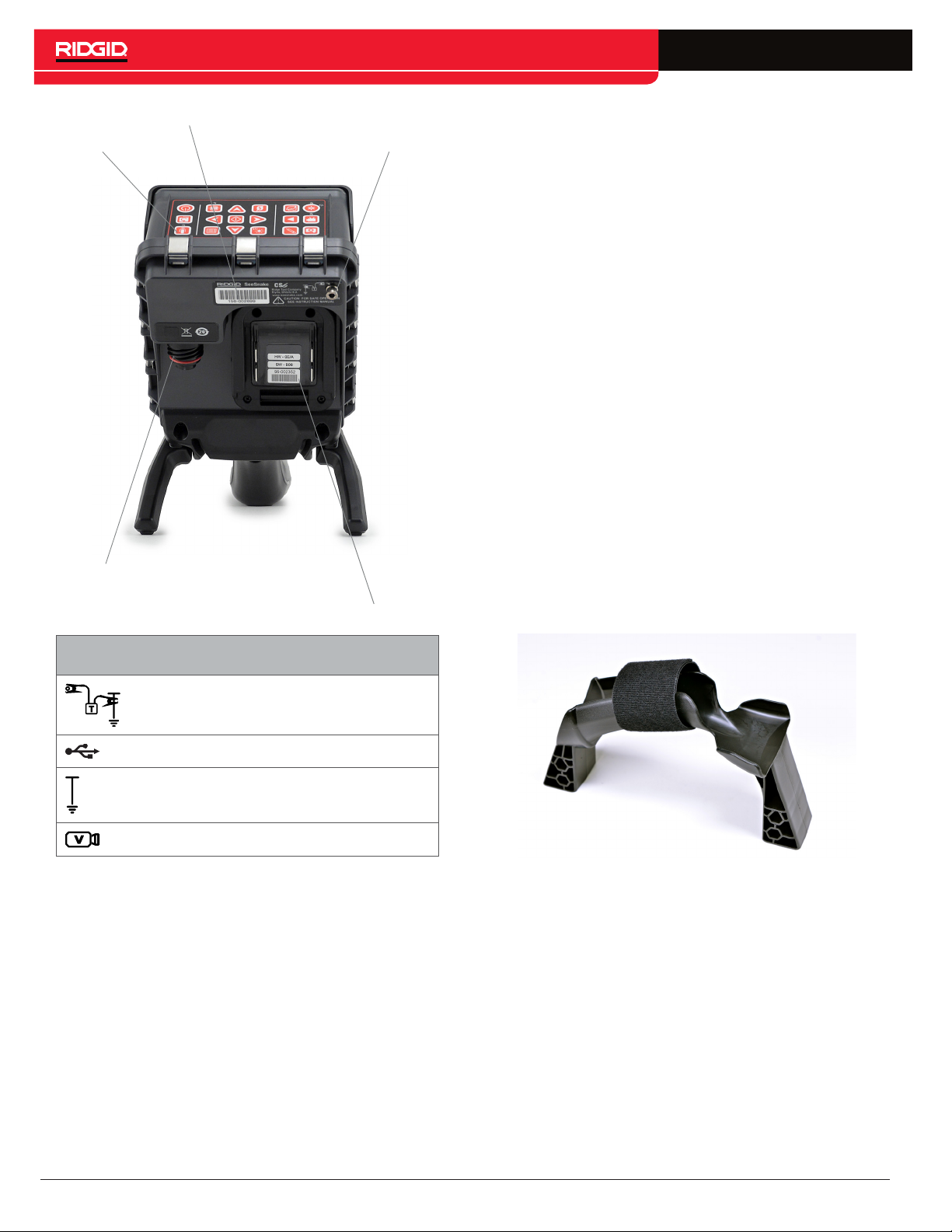
Keypad
Serial Number Label
Transmitter Clip-On Terminal
Front Cover and Kick Stand
The front cover reduces glare when open, and protects the LCD display when closed. Keep the front cover
closed to protect the display during transport.
Use the kick stand to adjust the angle of your display for
better visibility and stability. During transport, flip up the
kick stand.
USB Port Cover
Close the USB port cover to protect the USB drive and
USB port during inspections and transport.
Note: The maximum USB drive length for the USB port
cover to close is 50mm [2in].
Docking Handle
The CS6 is designed to dock onto the See Snake Max
rM200, but it can also fit into the dock for the See Snake
microReel, microDrain, and nanoReel. A docking handle is standard equipment for the rM200 or can be purchased as an accessory for use with other reels.
See Snake System
Connection Socket
Connection Icons
Transmitter Clip-On Terminal
USB Port
Functional Earth
See Snake System Cable Connection
Battery Shoe
To secure the CS6 onto the rM200, wrap the docking
handle’s velcro strap over the CS6’s handle. The CS6
may fall out of the docking handle if it is not secured by
the velcro strap.
Note: Refer to the See Snake Max rM200 manual for instructions on how to install the docking handle.
10 – English – CS6
Page 11
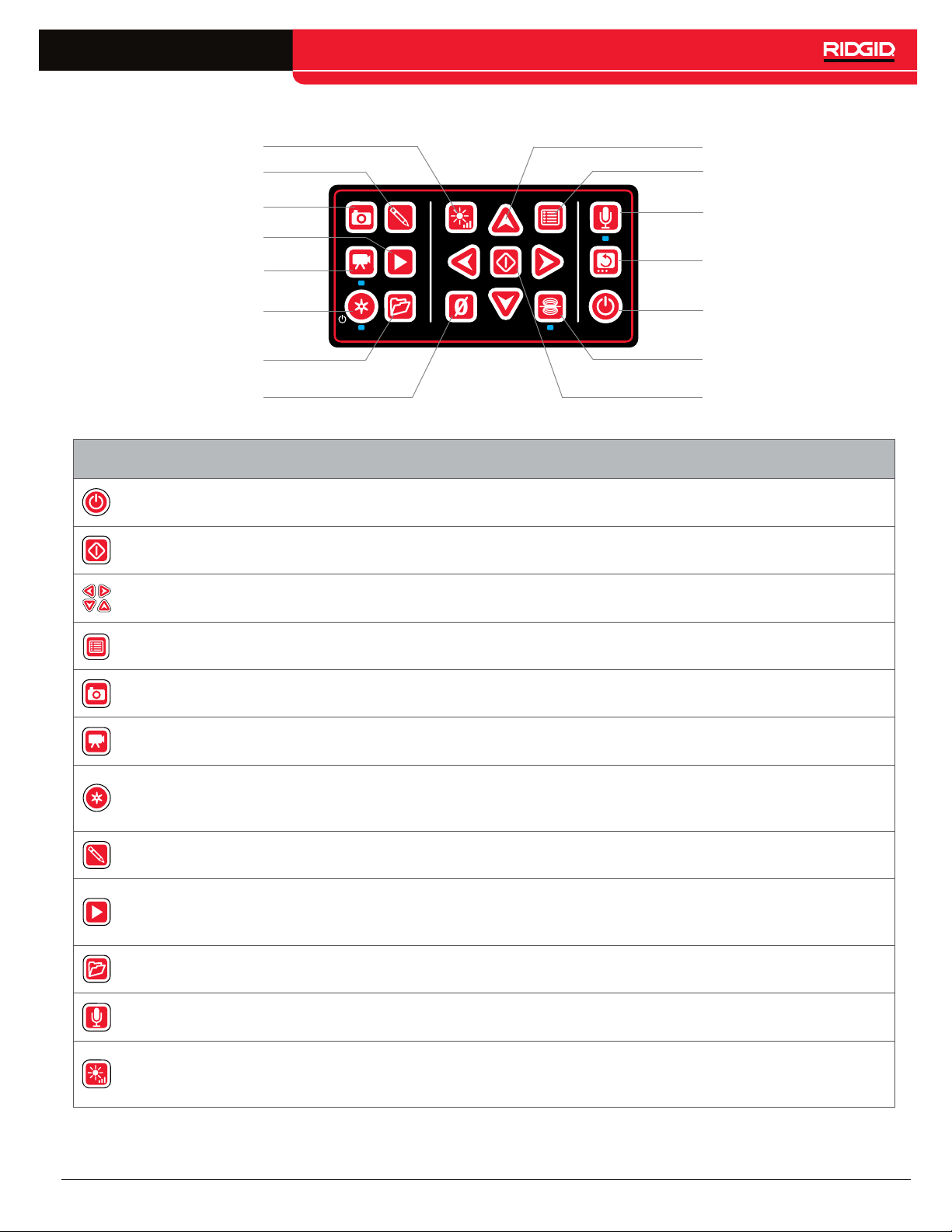
Keypad Overview
LED Brightness Key
Text Key
Arrow Keys
Menu Key
Photo Key
Review Key
Video Key
Autolog Key
Job Manager Key
Zero Key
Keys and Functions
Power Key Power the system on and off.
Select Key
Arrow Keys
Menu Key
Select highlighted items and apply changes. When a recording is in progress,
press to pause and resume video and Autolog video recordings.
Navigate through menus and screens and increase or decrease volume during
playback.
Open the menu to edit settings, reel options, LCD settings, time, date, region
options, view battery, and other information. Press to exit out of tabs and screens.
Microphone Mute Key
Image Flip Key
Power Key
Sonde Key
Select Key
Photo Key
Video Key Start and stop video recording.
Autolog Key
Text Key Enter text to display as an on-screen custom overlay.
Review Key
Job Manager Key
Microphone Mute Key
LED Brightness Key
Take a photo. Photos can be taken anytime during video or Autolog video
recording and while the recording is stopped or paused.
Start and stop Autolog video recording. If a USB drive is inserted, use to quickstart an inspection. Do two things with one key press: power on the system and
start recording Autolog video.
Open the Job Review screen to review captured media, playback videos, add
notes, enter customer and job location information, and preview the report for the
open job.
Open the Job Manager to view the job list, create a new job, preview an existing
job, enter company information, or delete jobs from the USB drive.
Enable or disable the microphone. Can also be used to mute audio during video
playback.
Control the brightness of the LEDs in the camera. Press to cycle through
brightness levels or press once and use the Arrow keys to increase or decrease
the brightness.
CS6 – English – 11
Page 12
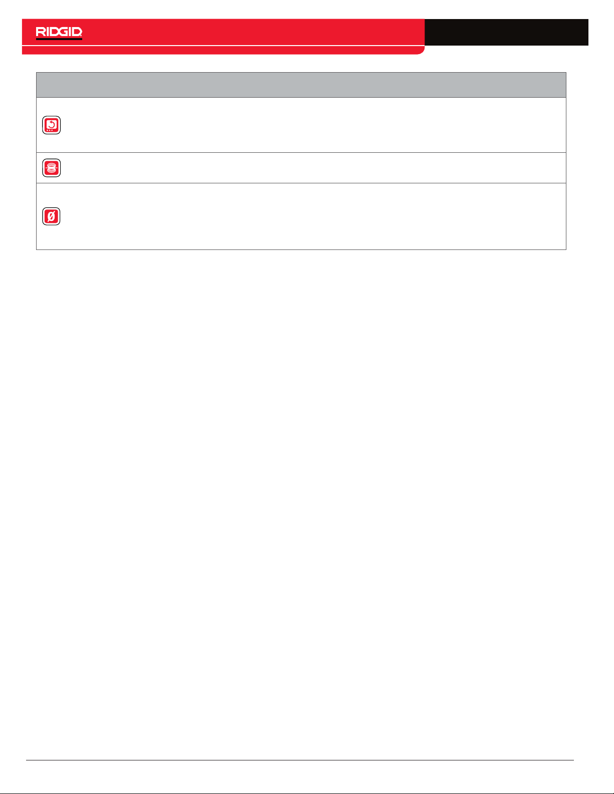
Keys and Functions
A short press (<1 second) rotates the image 180 degrees during live view.
Image Flip Key
Sonde Key Enable or disable the sonde.
Zero Key
The rotated image appears in captured media. You can also use it to flip the
entire user interface 180 degrees for situations where your equipment setup is
restricted. A long press (>3 seconds) rotates the user interface.
A long press (>3 seconds) sets the system measurement to zero at the beginning
of an inspection. Use a short press (<1 second) to take a temporary segment
measurement. A second short press will end temporary segment measurement
and return to system measurement.
Note: The temporary segment measurement appears in brackets.
12 – English – CS6
Page 13
Operating Instructions
WARNING
Wear appropriate protective equipment such as latex
or rubber gloves, goggles, face shields, and respirators when inspecting drains that might contain hazardous chemicals or bacteria. Always wear eye protection against dirt and other foreign objects.
Do not operate the CS6 if you or the equipment are
standing in water. Operating the equipment while
in water increases the risk of electrical shock. Rubber-soled, non-slip shoes can help prevent slipping
and electrical shock on wet surfaces.
Placement
When arranging your equipment at a work site, position
the CS6 so the keypad is easy to reach and the display
faces away from direct sunlight. Place the See Snake
camera reel near the pipe entrance to make it easier
to manipulate the push cable while viewing the display.
Make sure the CS6 and See Snake camera reel are stable.
NOTICE
When used outdoors or in wet locations,
use battery power only. Protect the battery from precipitation.
Connecting to a Camera Reel
The CS6 can connect to any See Snake camera reel with
the See Snake system cable.
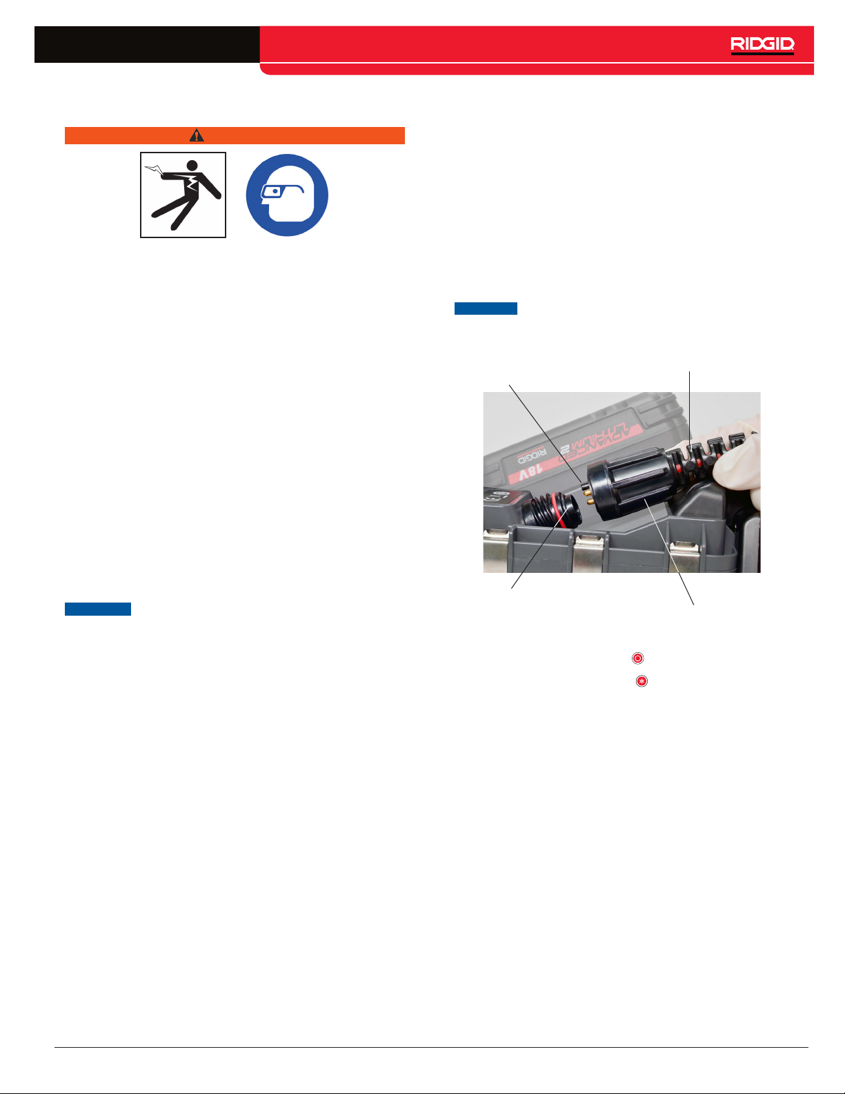
1. Unwrap the system cable from the cable wraps.
2. Pull back the outer locking sleeve on the system
cable connector.
3. Align the connector ridge and plastic guide pin with
the socket and push the connector straight in.
4. Tighten the outer locking sleeve.
NOTICE
Guide Pin
Socket
5. Power on the system:
Note: A USB drive must be inserted to capture
media.
Only twist the outer locking sleeve. To
prevent damage to the pins, never bend
or twist the connector.
Connector Ridge
Outer Locking Sleeve
• Press the Power key to power on the system.
• Press the Autolog key to quick-start an inspection. Do two things with one key press: power on
the system and start recording Autolog video.
CS6 – English – 13
Page 14
Powering the CS6
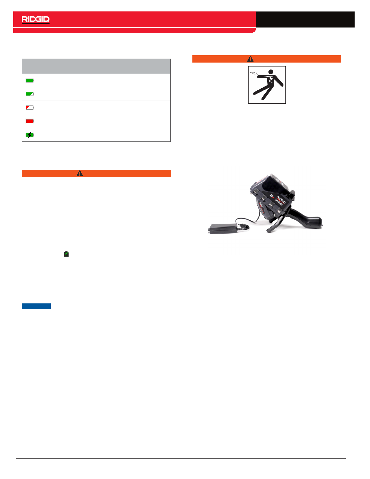
Power Icons
The battery is fully charged.
The battery is partially charged.
AC Adapter
WARNING
The battery is low.
Replace the battery.
The AC adapter is connected.
18 V Li-Ion Rechargeable Battery
WARNING
Only use the CS6 with a compatible battery. Use of
any other batteries may create a risk of fire and/or
injury.
The CS6 is powered by a compatible 18 V Li-Ion rechargeable battery. Slide the battery into the battery shoe
and lock into place.
To prevent data loss when the low battery warning displays and the battery icon flashes, stop any in-progress recordings and power off the system as soon as
the check mark displays. Resume use after the battery
has been recharged or replaced.
When the battery reaches a critical level, the system
stops any in-progress recordings and powers off. Data
may be lost. Resume use after the battery has been recharged or replaced.
The AC adapter is not waterproof and is intended for
indoor use only. To prevent electrical shock, do not
use with an AC adapter outdoors or in wet locations.
The CS6 can be powered with an optional AC adapter.
Slide the AC adapter into the battery shoe and lock into
place.
NOTICE
14 – English – CS6
Observe your battery’s charge status
closely. Using a battery with an extremely low charge may result in unexpected
power loss, which may result in data
loss and corruption.
Page 15
Integrated Counter
All See Snake Max camera reels and many original SeeSnake camera reels come equipped with an integrated counter. The integrated counter measures the total
length of the extended push cable, or system measurement.
The integrated counter can also be used to measure a
segment from a temporary zero point, such as a pipe
head or joint, while still keeping track of the system measurement.
System Measurement
Set the system starting zero point wherever you want
your inspection measurement to begin. This may be at
the pipe entrance or it may be farther down the line.
Press and hold the Zero key for three seconds to
set the system measurement to zero.
Inspection Overview
The See Snake CS6 can be used for basic or advanced pipe inspections. To perform a basic inspection, connect the CS6 to a See Snake camera
reel, power on the system, push the push cable
through the pipe, and observe the display. An advanced inspection additionally involves capturing
media and delivering reports to your customer.
1. Place the See
CS6 near the pipe entrance.
onnect the CS6 to the camera reel with the
2.
C
system cable.
3.
ress the Power key
P
tem. Alternatively, insert a USB drive into the
monitor’s USB port and press the Autolog key
to quick-start the inspection.
e camera reel and the
Snak
to power on the sys-
Temporary Segment Measurement
To measure a temporary segment distance during an inspection, press the Zero key to set a temporary zero
point. The temporary zero point is indicated with brackets. To clear the temporary segment measurement and
return to the system measurement, press the Zero key
again.
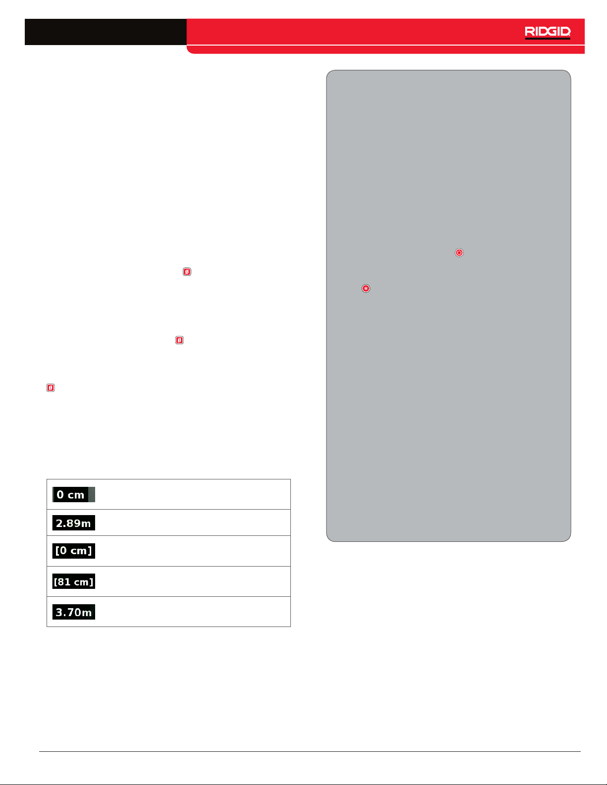
Measurement Display
The system measurement is displayed in the bottom left
corner of the screen. A temporary segment measurement is represented by brackets.
Inspection start point. System
measurement is set to zero.
Distance from system zero start point.
Temporary segment measurement
start point.
Distance from temporary zero start
point.
4.Carefully put the camera into the pipe. Protect the push cable from sharp edges at the
pipe entrance.
5.Push the camera through the pipe and observe the display.
6. Advanced Options:
Set the s
•
porary segment distance measurement.
C
apture media.
•
A
•
dd custom overlay.
Locat
•
R
eview the job, playback captured media,
•
and preview the report.
Deliv
7.
er the USB drive directly to your customer or insert the USB drive into your computer
to edit in HQ.
ystem zero point, or take a tem-
e an inspection point or path.
Return to measuring from the start
zero.
CS6 – English – 15
Page 16
Capturing Media
The CS6 does not have internal storage. A USB drive
with available space must be inserted to capture media
and create reports. Media automatically saves to the
open job as it is captured, continuously throughout the
inspection. Each job then generates a report which includes captured media, company and customer information, and notes.
Reviewing Recent Captures
Press the Review key to view the most recent capture.
Use this key to easily playback a video or Autolog video
recording. From the job review screen you can review all
the captured media in the open job and access the report preview. Press the Menu key to exit and return to
live view.
A USB drive is not necessary for basic inspections, including live view, operating the sonde, setting zero
points, or controlling the camera brightness.
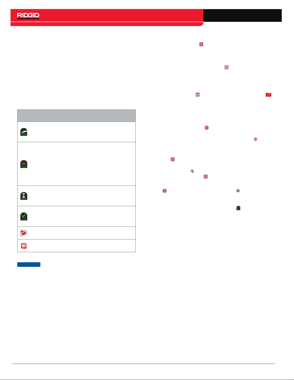
Interface Icons
A USB drive is inserted. The bar below the
USB drive indicates the remaining capacity
on the USB drive.
Captured media is actively being written
to the USB drive. The percentage shown
represents how much of the captured
media has been written. In this example, 99
percent of the captures have been saved
to the USB drive. Do not remove the USB
drive.
Captured media is being processed and
saved to the USB drive. Do not remove the
USB drive.
Processing is complete and all the media
has been saved. It is safe to remove the
USB drive.
Taking Photos
Press the Photo key to take a photo. The photo icon
displays briefly and the photo is automatically saved onto
the USB drive in the open job.
Recording Autolog Video
Press the Autolog key to start and stop recording
Autolog video. When Autolog video is recording, the LED
below the key is lit and a red Autolog video icon is displayed.
Pause the Autolog video recording by pressing the Select key . When the Autolog video recording is paused
the red Autolog video icon changes to a black Autolog
video pause icon . Resume Autolog video recording by
pressing the Select key again.
To stop an Autolog video recording, press the Autolog
key . The black Autolog video icon indicates that
the Autolog video recording is stopping and processing.
Wait for a moment while the recording is processed and
saved to the open job. The check mark means the recording has been successfully processed and saved to
the USB drive.
A job is open.
The live view image is flipped.
NOTICE
16 – English – CS6
Premature removal of the USB drive may
result in data loss and corruption.
Page 17
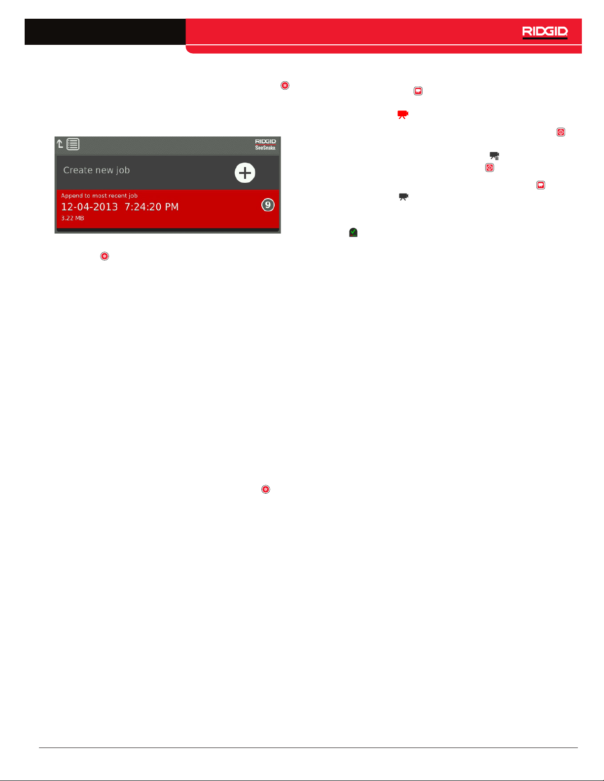
Use Autolog video recording to quick-start an inspection. When the system is off, press the Autolog key
to power on and automatically begin recording Autolog
video. When prompted, choose Create new job or Append to most recent job.
Note: You cannot power off the system by pressing the
Autolog key .
What is Autolog Video?
Autolog videos are made of continuous audio recording
and variable frame rate compressed video. The video
compression rate of Autolog video is approximately onetenth the size of traditional video recording. Autolog video
looks similar to traditional video recordings but achieves
a much higher compression level (lower file size) by capitalizing on the static nature of pipe inspection video and
updating the image more slowly when the camera is not
moving.
Recording Video
Press the Video key to start and stop recording video.
When video is recording, the LED below the key is lit and
a red video icon is displayed.
Pause the video recording by pressing the Select key .
When the video recording is paused, the red video icon
changes to a black video pause icon . Resume video
recording by pressing the Select key again.
To stop a video recording press the Video key . The
black video icon indicates that the video recording is
stopping and processing. Wait for a moment while the recording processes and saves to the open job. The check
mark means the recording has been successfully processed and saved to the USB drive.
When the camera is moving through the pipe, Autolog
video records five images per second to provide context.
When the camera stops moving, Autolog video records
one image every five seconds.
The substantial decrease in file size, compared to traditional video recording, makes storage and transfer of
files easier and less expensive. The Autolog key can
be used to quick-start an inspection. Press it when the
system is off and it will power on the unit, create a new
job, and start an Autolog video recording. With Autolog
video you can record the entire pipe inspection in a small
file format while recording video and taking pictures.
CS6 – English – 17
Page 18
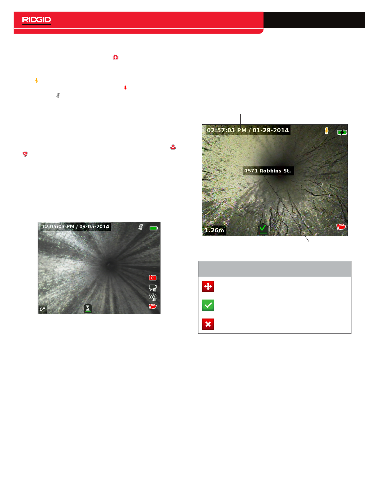
Recording Audio
Press the Microphone Mute key to enable or disable
audio recording. When the microphone is enabled, the
LED below the key is lit, and the microphone icon is yellow . When video is recording and the microphone is
enabled, the microphone icon is red . The microphone
icon is gray when the microphone is disabled.
By default, the microphone is enabled and audio records
continuously during both Autolog video and video recording so your narrations are intact and uninterrupted.
When video or Autolog video recording is paused, audio
is also paused.
During playback, press the Up and Down Arrow keys
to adjust the volume of the recorded audio.
Multi-Capture
Video and Autolog video can be recorded simultaneously and independently of each other. Both recording types
can be started and stopped without affecting the other.
Pausing will affect both recording types. Photos can be
taken during video and Autolog video recording.
Custom Overlay
Note: See the Overlay Details section for configuration
details for time/date and count display.
Custom overlay text is superimposed onto the video
image and is a permanent part of the captured media
files (photos, video, and Autolog video). The custom
overlay appears on captured media until deleted.
Date/Time Overlay
Count Overlay
Custom Overlay Icons
Move
Save
Discard Discard changes and exit.
Note: Some See Snake camera reels are equipped with
a counter that generates text which can be superimposed onto the camera image. The counter’s title features are controlled by the reel’s counter keypad and
are independent from the CS6. You cannot edit or remove on-screen text created by the CS6 keypad with
the reel’s counter keypad.
Adjust the position of the text
box.
Save text so that it appears in
all media.
Custom Overlay
18 – English – CS6
Page 19
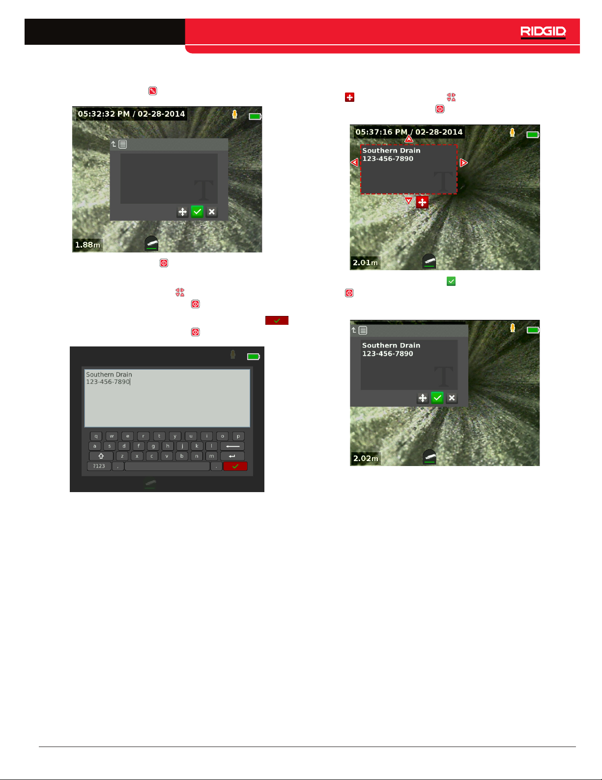
Adding Custom Overlay
1. Press the Text key to open the text box.
2. Press the Select key to open the on-screen keyboard.
• Use the Arrow keys to highlight characters
and press the Select key to enter them.
• To save the text, highlight the save icon
and press the Select key .
3. Reposition the text wherever you want it on the
screen by highlighting and selecting the move icon
. Use the Arrow keys to move the text box and
press the Select key to save the placement.
4. Highlight the save icon and press the Select key
to superimpose the text onto the video image
and exit back to live view.
CS6 – English – 19
Page 20
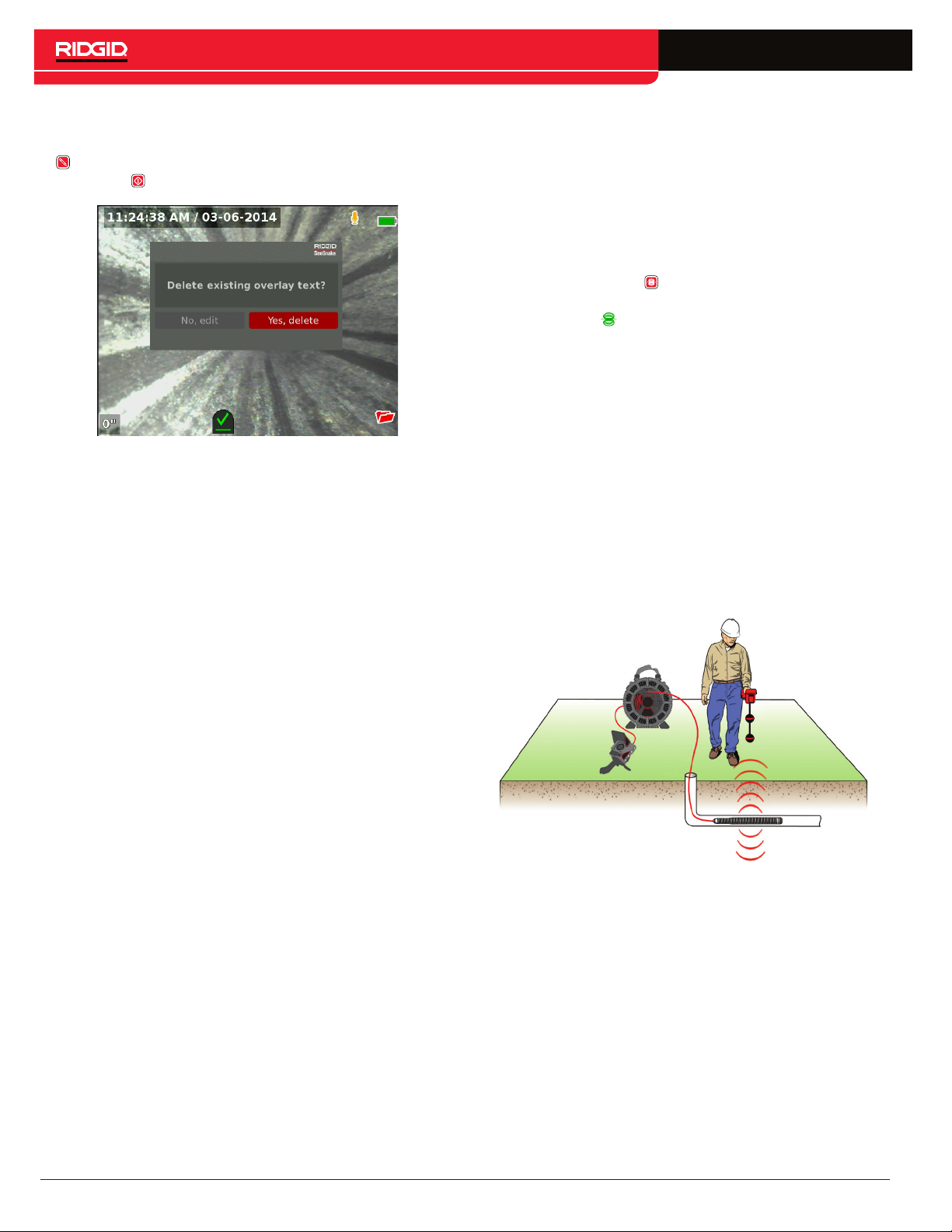
Delete or Edit Custom Overlay
To delete or edit existing overlay text, press the Text key
, highlight either Yes, delete or No, edit, and press the
Select key .
Locating the Sonde
Many See Snake camera reels have an integrated sonde
which you can use to locate a point of interest in the
pipe. The sonde is located in the spring and is assembled between the end of the push cable and the camera.
The sonde transmits a locatable 512Hz signal that can
be detected by receivers such as the RIDGID SeekTech
SR-20, SR-24, SR-60, Scout™, or NaviTrack®II.
Press the Sonde key to enable or disable the sonde.
When the sonde is enabled, the LED by the keyis lit and
the sonde icon is displayed. The 512Hz sonde signal
can cause interference lines that may be visible on captured media.
To locate the sonde, follow these steps:
1. Power on the receiver and set it to sonde mode.
2. Locate the sonde’s general direction so you know
which way the pipe goes:
• Enable the sonde and push the push cable no
more than 5 m [15 ft] into the pipe.
• Sweep the horizon with the receiver in a slow
arc.
3. The signal strength is highest where the receiver
detects the sonde.
20 – English – CS6
Note: For additional instructions on sonde locating, refer
to the manual for the receiver model you are using.
Page 21
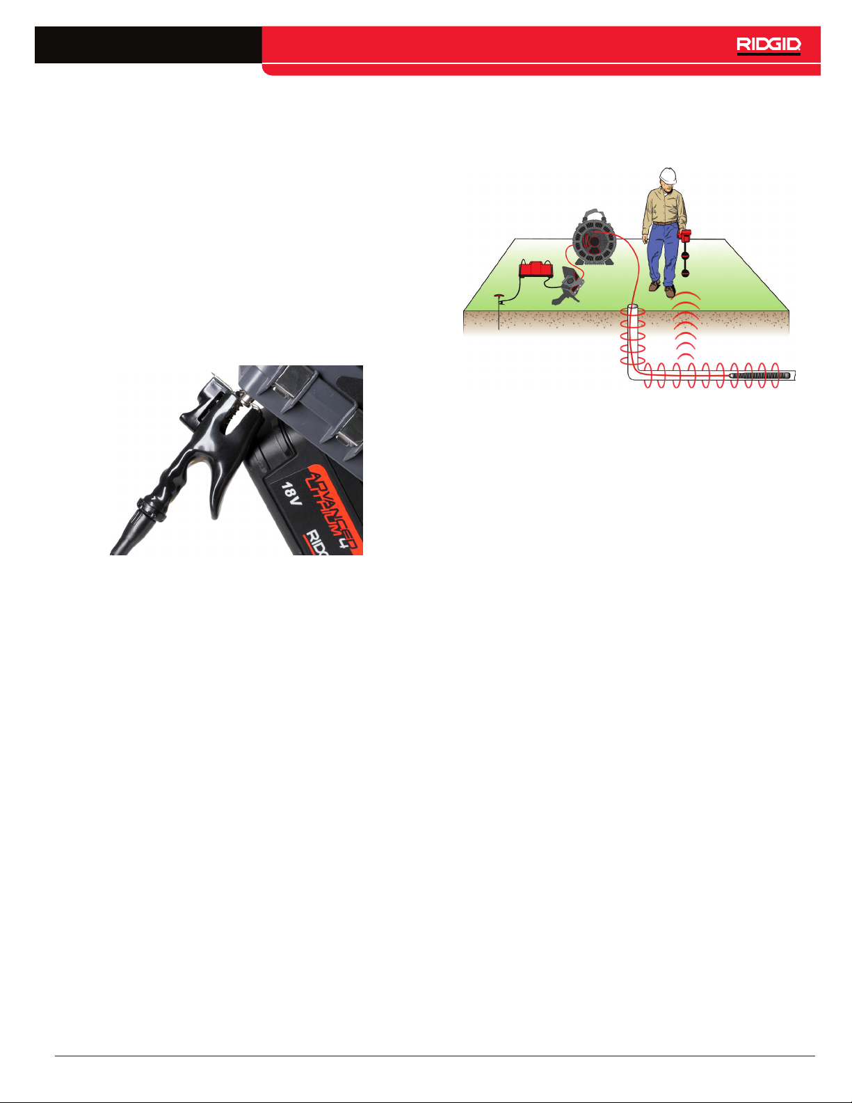
Line Tracing the Push Cable
You can locate the path of a pipe by line tracing the push
cable. This is especially useful for inspecting non-metallic or non-conductive pipes. Line trace the push cable by
using a transmitter to induce current onto the push cable.
Note: The CS6 must be powered on and connected to a
See Snake camera reel and transmitter to line trace the
push cable.
To line trace the push cable, follow these steps:
1. Push the transmitter’s ground stake into the ground
and clip one of the transmitter’s leads to it.
2. Clip the other lead to the transmitter clip-on terminal
on the back of the CS6.
4. Power on the receiver and set it to the same frequency as the transmitter.
5. Trace the line.
Note: For additional instructions on line tracing, refer to
the manuals for the transmitter and receiver models you
are using.
3. Power on the transmitter and set your desired frequency. For best results, use frequencies 33kHz
and higher.
CS6 – English – 21
Page 22
Job Review
Press the Review key to open the job review screen.
During an inspection, the job review screen opens onto
the most recently captured media. It is recommended to
stop active recordings before previewing as you cannot
view active recordings in progress.
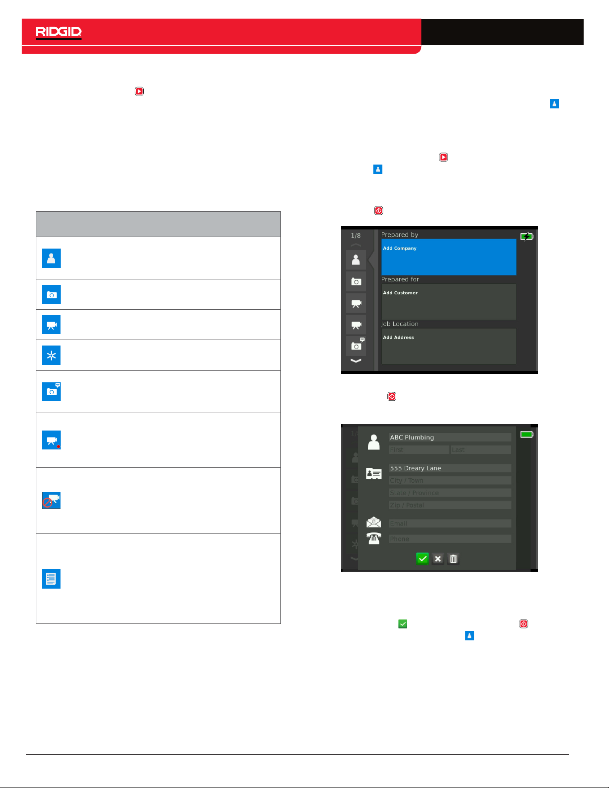
Entering Job Details
You can add your company’s information, customer information, and the job location from the contact tab ,
at the top of the job review screen. The information you
enter in the contact tab’s fields is used in the report
header.
From the job review screen you can view and edit the
open job’s captured media, add notes to individual captures, choose which captures to include in the report,
enter customer information, and preview the report.
Job Review Tabs
Enter company information,
Contact
Photo View and add notes to photos.
Video
Autolog
Video
Notes
Recording
customer information, and job
location details.
Playback and add notes to
videos.
Playback and add notes to
Autolog videos.
A text bubble indicates that a
note has been added to this
capture.
The red dot means a recording
is in progress. You cannot
playback videos or Autolog
videos during recording.
1. Press the Review key and navigate to the contact tab .
2. Highlight the subject you want to enter information
for: company, customer, or address. Press the Select key to open the text form.
3. Highlight the field you want to edit and press the
Select key to open the text box and use the onscreen keyboard to enter text.
Excluded
Media
Report
Information
22 – English – CS6
This individual capture is
marked as excluded and will
not appear in the report but is
still part of the job and present
on the inserted USB drive.
View media statistics such
as photo count, video count,
and Autolog video count. View
whether contact information
was entered into report. You
can preview the job report from
this screen.
Note: Refer to the Custom Overlay section for instructions on how to use the on-screen keyboard.
4. Repeat for other fields and, when done, highlight
the save icon and press the Select key to save
and return to the contact tab .
Page 23
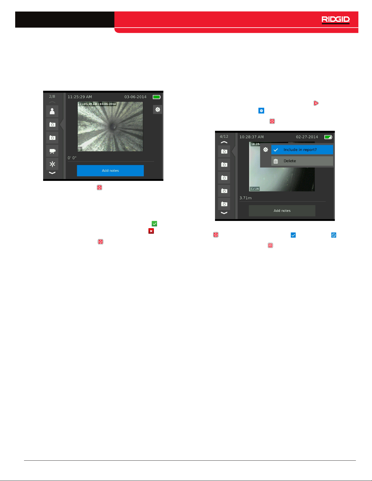
Adding Notes to Media
You can add notes to individual captures (photos, videos,
or Autolog videos) from the job review screen.
1. Navigate to the capture you want to add a note to
and highlight Add notes.
2. Press the Select key to open the text box and use
the on-screen keyboard to enter text.
Note: Refer to the Custom Overlay section for instructions on how to use the on-screen keyboard.
Excluding Media
By default, all captured media is included in the job report. If desired, you can mark specific captures to be excluded from the report without deleting them from the job
permanently. This keeps the media on the USB drive but
omits it from your report.
1. Navigate to the media you want to exclude from the
report and press the Right Arrow key to highlight
the settings icon .
2. Press the Select key .
3. To save the note, highlight the save icon . To discard the note, highlight the discard icon .
4. Press the Select key .
Note: Text entered in the job review screen is saved to
the open job on the USB drive and transfers with the
media captures when imported into HQ.
3. Highlight Include in report and press the Select key
to toggle between include and exclude .
4. Press the Menu key to exit.
CS6 – English – 23
Page 24
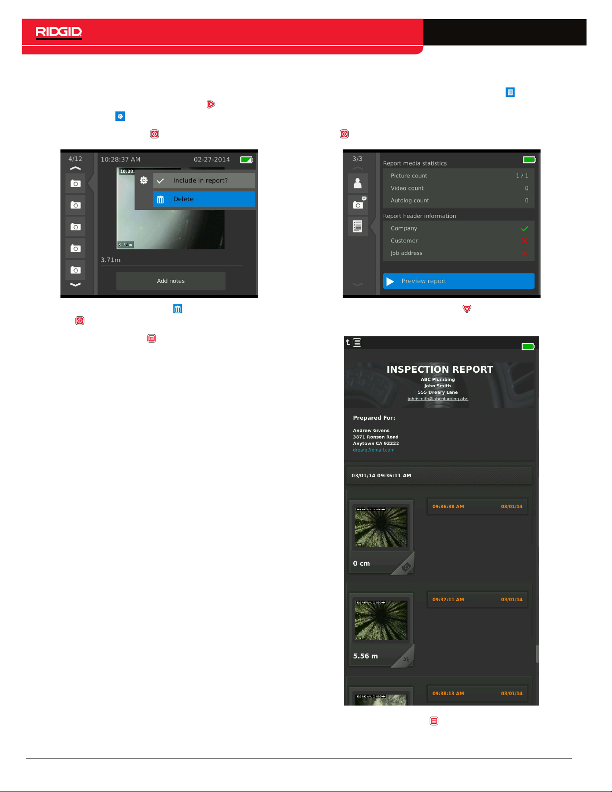
Deleting Media
1. Navigate to the media you want to delete from the
job and press the Right Arrow key to highlight the
settings icon .
2. Press the Select key .
Previewing the Report
1. Navigate to the report information tab , at the bottom of the job review screen.
2. Highlight Preview report and press the Select key
.
3. Highlight the delete icon and press the Select
key .
4. Press the Menu key to exit.
Note: Deleting media from the job report permanently
deletes it from the job.
3. Press the Down Arrow key to scroll through the
report preview.
24 – English – CS6
4. Press the Menu key to exit.
Page 25
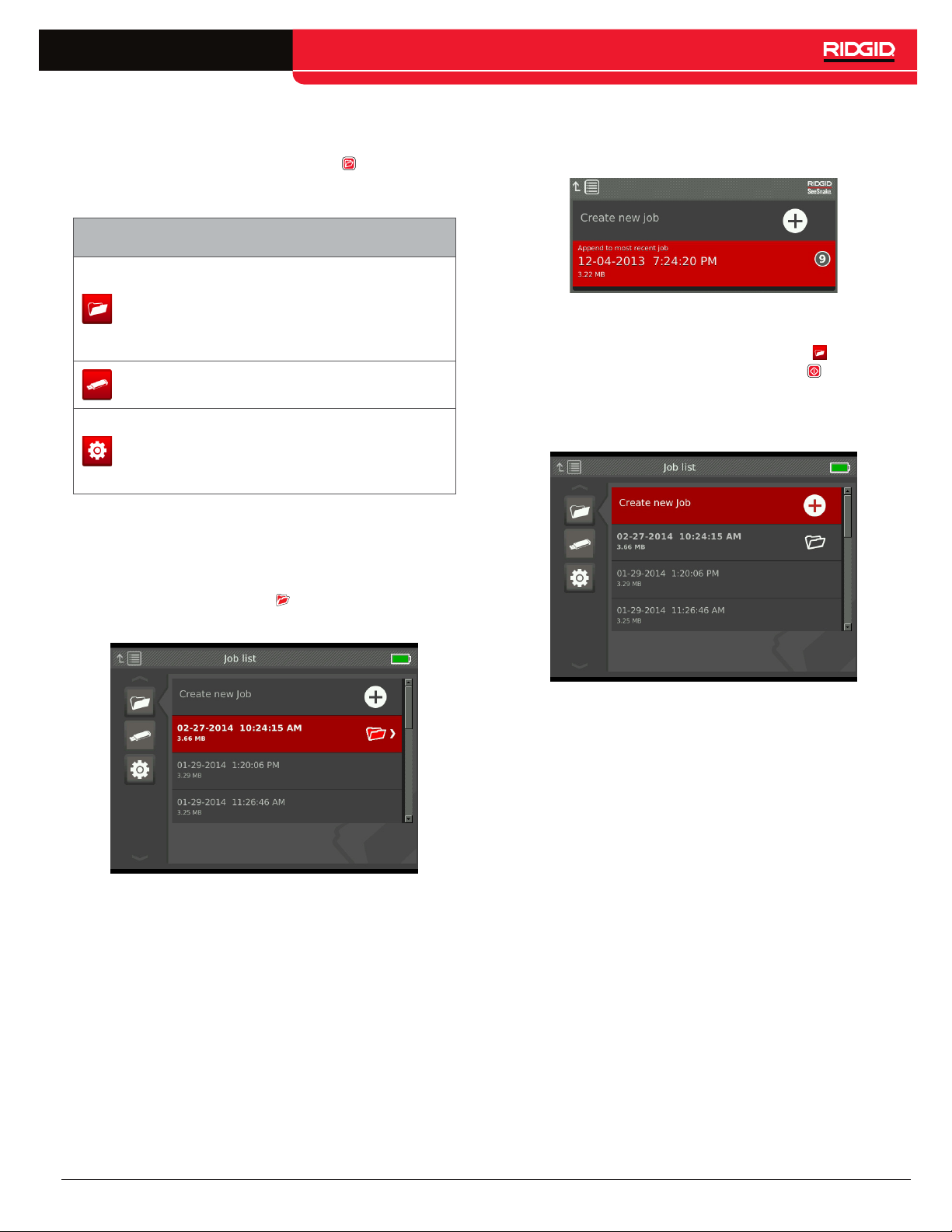
Managing Jobs
All jobs saved on the USB drive are listed in the Job
Manager. Press the Job Manager key to access the
following tabs: Job list, USB options, and Job settings.
Job Manager Tabs
Contains a list of all the jobs
on the USB drive. Create
Job List
USB Options
Job Settings
Job List
Media automatically saves to the open job as it is captured, continuously throughout the inspection. When a
job is open, the open job icon displays in live view and
in the job list.
new jobs or open and close
jobs. Preview the open job or
change which job is open.
Permanently delete all jobs
from the USB drive.
Add your company
information and choose to
have it automatically entered
in reports.
To capture media when no job is open, select Create
new job or Append to most recent job. New media saves
to your selection.
Create New Job
To create a new job, go to the job list tab , highlight
Create new job, and press the Select key . New jobs
are named according to the date and time they were created. When a new job is created, it becomes the open
job.
CS6 – English – 25
Page 26
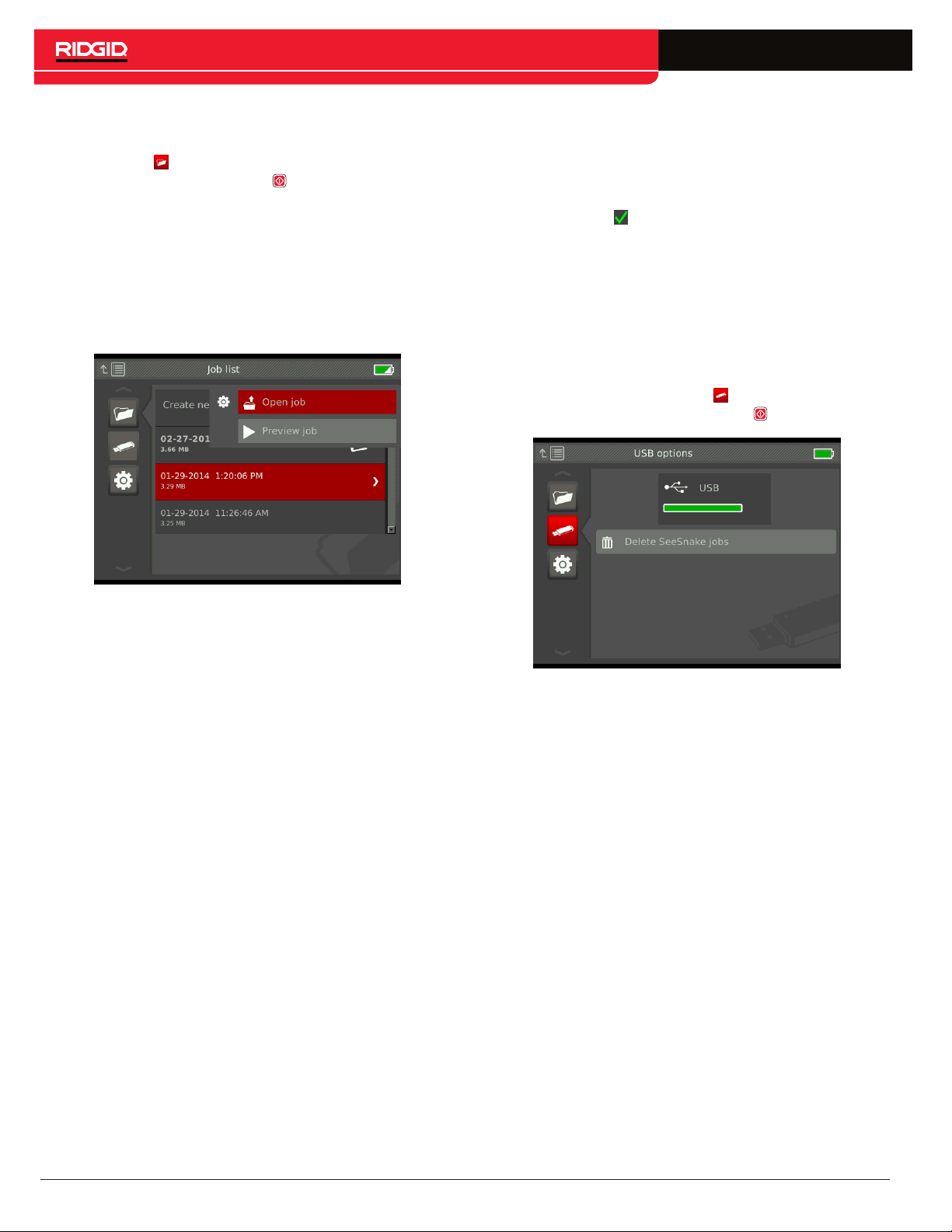
Open Job/Preview Job
To open or preview jobs stored on the USB drive, go to
the job list tab , highlight the job you want to preview or
open, and press the Select key .
• Open job saves newly captured media to the highlighted job.
• Preview job opens the job review screen and displays all captured media and any job or customer
information that has been entered. You can also add
and edit customer and job information in the job review screen.
USB Options
The USB options tab shows the amount of space available on the USB drive. The red section of the bar represents the amount of data already on the USB drive and
the green section indicates how much space is available.
The check mark means that it is safe to remove the
USB drive.
Note: Premature removal of the USB drive may result in
data loss and corruption. The USB indicator LED flashes
when data is being written.
Delete All Jobs
To permanently delete all the jobs from the USB drive,
navigate to the USB options tab , highlight Delete SeeSnake jobs, and press the Select key .
Note: If a job is already open, you can close the job from
this menu.
Note: You can only delete all jobs on the USB drive, not
individual jobs. To delete specific jobs, view the USB
drive in HQ.
26 – English – CS6
Page 27
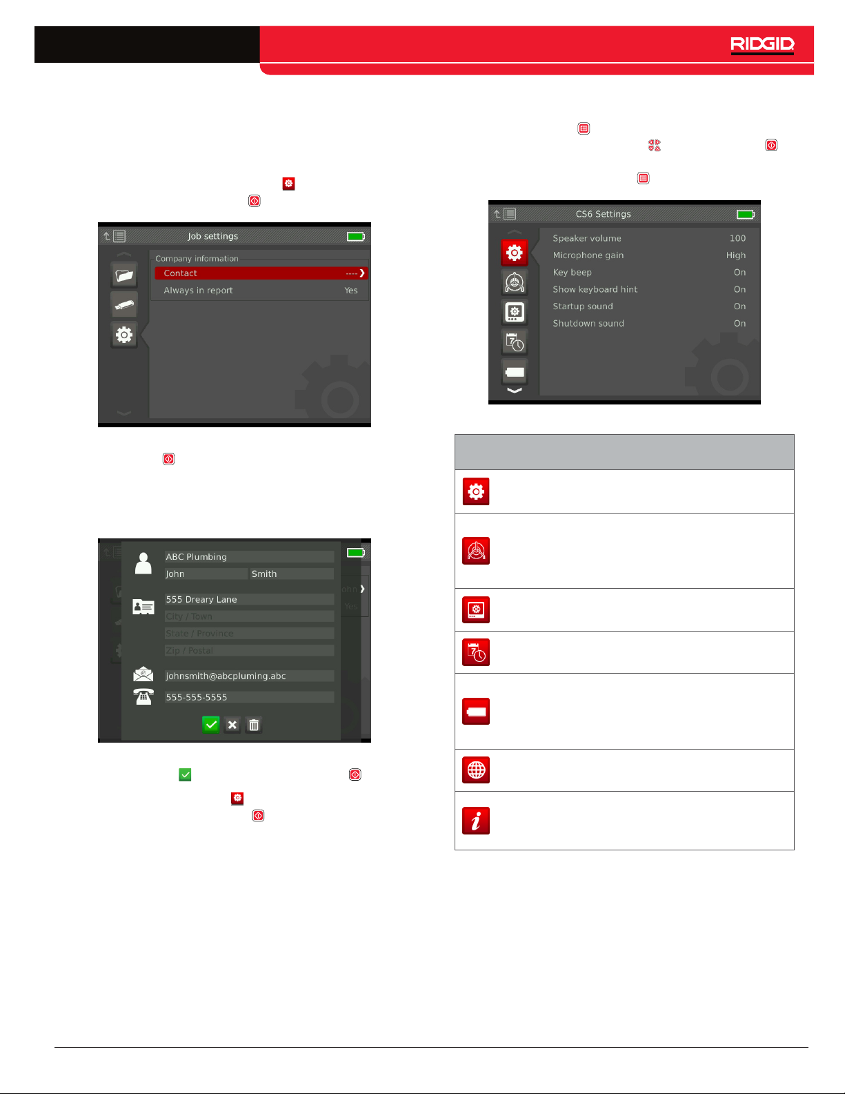
Job Settings
You can add your company information and choose
whether the information appears in the job report header by default.
1. Navigate to the job settings tab , highlight contact,
and press the Select key .
System Settings
Press the Menu key to access the menu tabs and edit
settings. Press the Arrow keys and Select key to
navigate through tabs, make selections, and to apply
changes. Press the Menu key to exit.
2. Highlight the field you want to edit and press the
Select key to open the text box and use the onscreen keyboard to enter text.
Note: Refer to the Custom Overlay section for instructions on how to use the on-screen keyboard.
3. Repeat for other fields and, when done, highlight
the save icon and press the Select key .
4. In the job settings tab , highlight Always in report
and press the Select key to toggle between Yes
and No.
Menu Tabs
CS6
Settings
Reel
Options
LCD
Settings
Date/Time Modify the date and time.
Battery Info
Region
Options
About
Adjust speaker volume, sound
settings, and keyboard settings.
Set when and how overlay
details are displayed,
measurement units, and default
sonde settings.
Adjust LCD display brightness
and contrast.
View battery type, serial
number, voltage sense
information, temperature,
current sense, and power.
Change language and other
locale specific settings.
View software version
information and restore system
settings.
CS6 – English – 27
Page 28
Overlay Details
Overlay details include the date and time of the inspection and the count measurement. You can choose when
and how these details are displayed on-screen and in
media. To make changes, navigate to the reel options tab
, highlight Overlay and press the Right Arrow key to
cycle through the options.
Overlay Details
Displays the date, time, and count
Display
Only
Video
Reel
measurement, but does not record on
media. Text size is adjustable for both
count and date/time.
Displays the date, time, and count
measurement, and records them to
media. Text size is preset for this mode.
Displays overlay entered on the drum
keypad of the connected reel. Text size
is preset for this mode.
Delivering Reports
One of the most valuable features of the CS6 is the ability to automatically build comprehensive, professionally
formatted reports as you work, making it quick and easy
to deliver reports to customers. These reports greatly enhance the way you communicate the results of your inspections with customers. In many cases you can hand
your customer a USB drive containing a report before
leaving the job site.
When delivering reports without editing in HQ, you can
see a preview of the report on the CS6 or view it on a
computer before giving a USB drive to your customer.
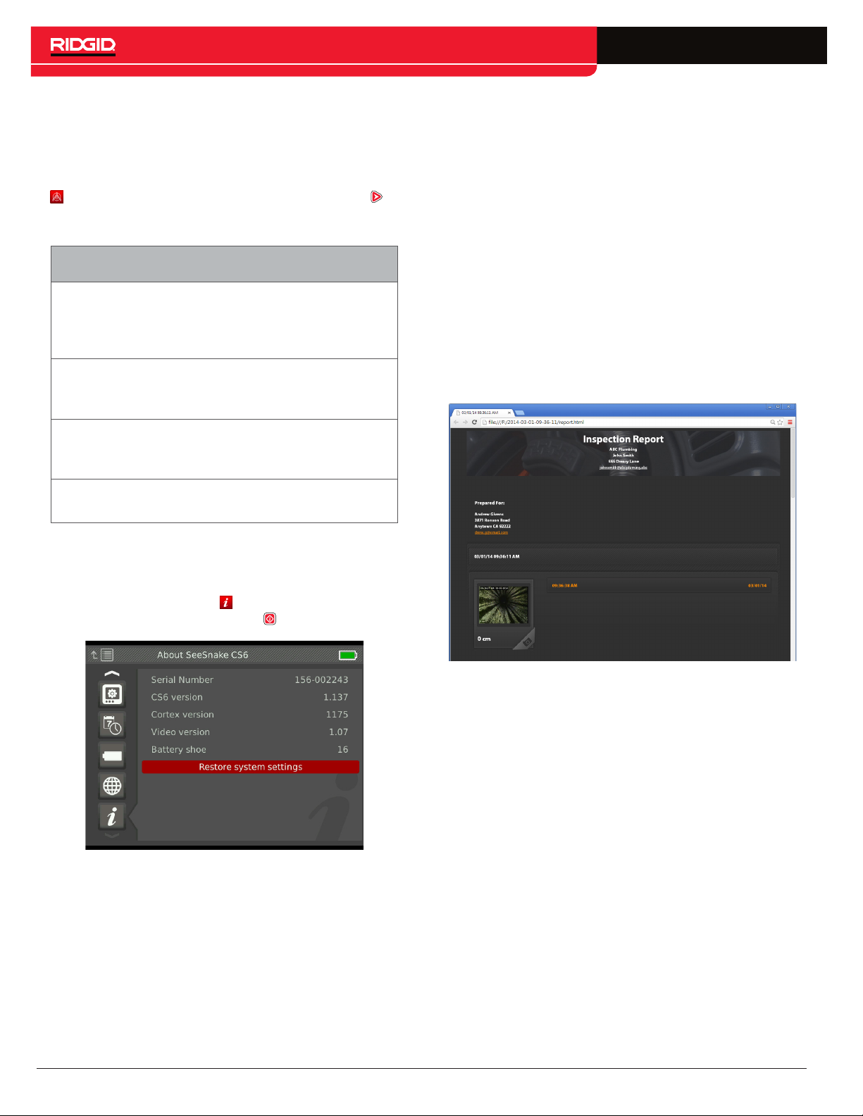
To view a report on your computer, follow these steps:
1. Insert the USB drive into a computer.
2. Open the file named “report.html.”
Off
The date, time, and count
measurement are not displayed at all.
Restoring System Settings
You can restore system settings from the main menu.
Navigate to the about tab , highlight Restore system
settings, and press the Select key .
Note: The report opens in a web browser, however an Internet connection is not necessary to view
the report.
3. Click on captured media to view full size photos and
to playback video and Autolog video.
4. Safely eject the USB drive from the computer.
To further customize the report or make additional edits,
insert the USB drive into a computer that has HQ installed. HQ automatically imports jobs from the USB
drive.
28 – English – CS6
Page 29
Software
HQ Software
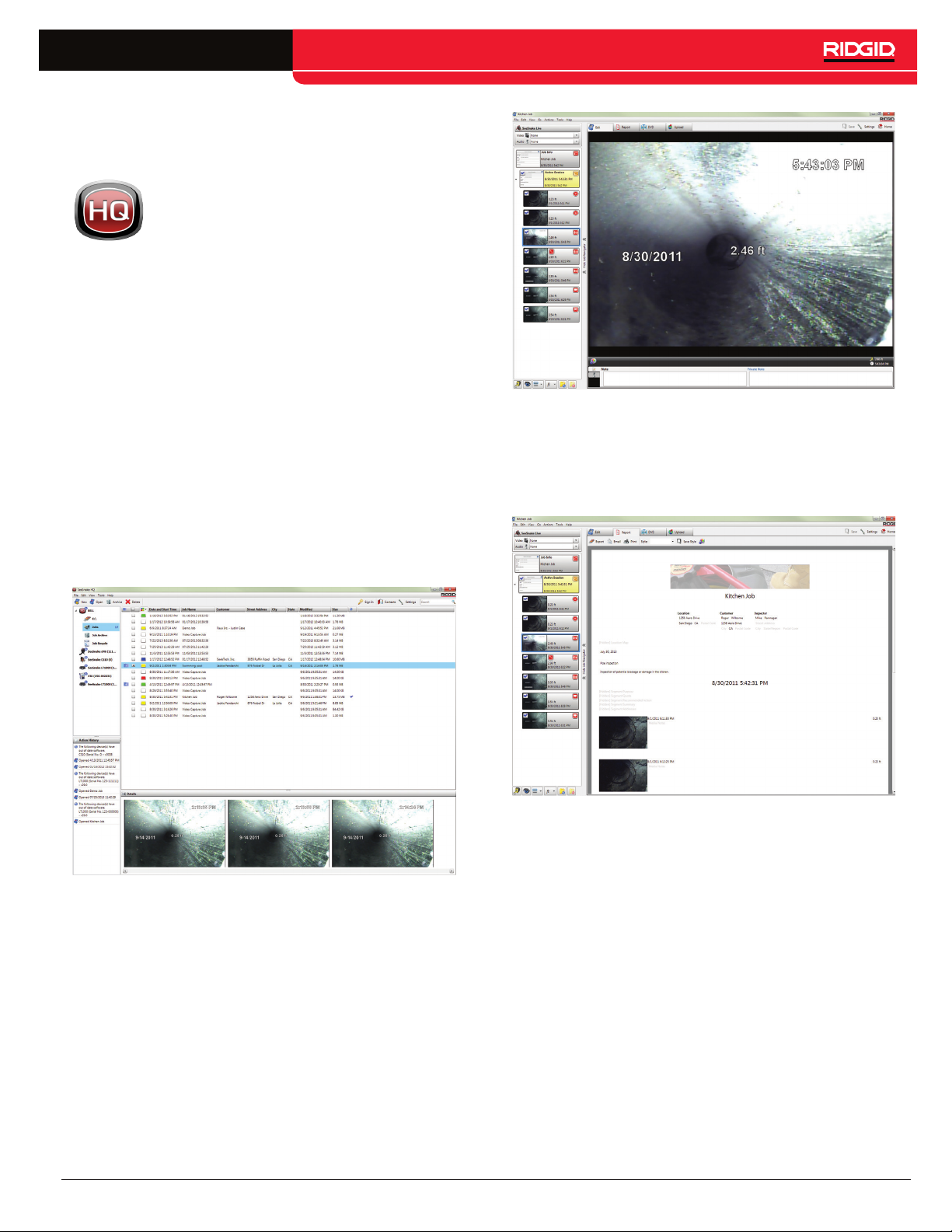
HQ is software designed to make it easier
for you to manage media captured during
inspections. Use HQ to organize and ar-
chive jobs, media, store customer information, customize reports, generate DVDs, and distribute
complete reports or individual media to customers.
8 GB USB drive included with your CS6 has HQ
The
preloaded.
ensures that the serial number for your CS6 is correctly registered in the Equipment Locker. Alternatively, you
can install HQ from the included disk or download
latest version
the
Software updates for the CS6 are released through HQ.
You must register your CS6 in HQ’s Equipment Locker to
receive updates.
About HQ
HQ can be installed on PCs running Windows 7, Windows 8, or Windows 8.1. The software is translated into
18 languages and localized for use worldwide.
Installing HQ from the included USB drive
You can generate and email a printable PDF from HQ or
create a multimedia job report for digital or DVD distribution. It is easy to customize the pre-built report styles
to feature your company’s logo and contact information.
You can also add promotional or informational photos
and video clips to reports.
HQ offers an array of tools to manage, group, and backup jobs, edit photos, create and edit video clips, add
notes, customer details, and job information.
Content
online service for storing and sharing inspection media
and reports.
in HQ can be uploaded to RIDGID Connect, an
CS6 – English – 29
Page 30
Updating CS6 Software
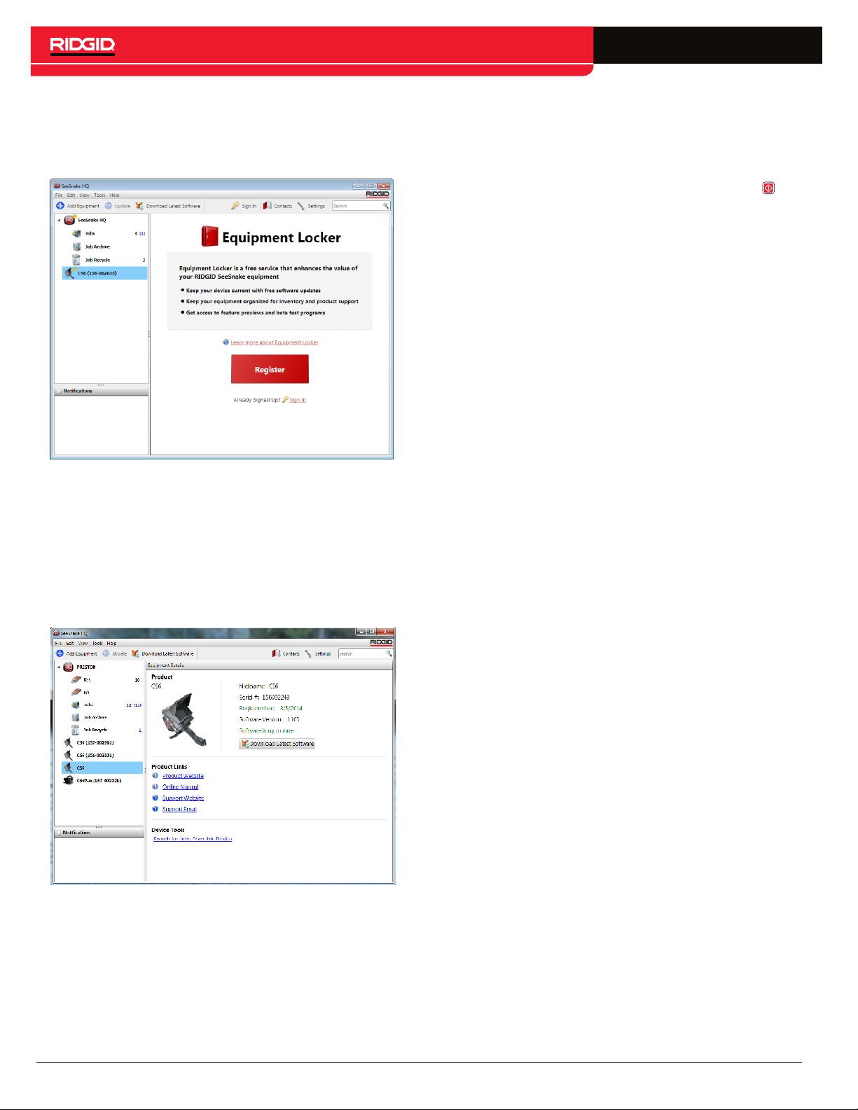
Register your CS6 in HQ’s Equipment Locker to be automatically notified when software updates become available.
Note: FAT32 formatting is required for installing updates.
USB drives larger than 32GB cannot be used.
4. Insert a USB drive into the computer and follow
HQ’s instructions to proceed.
5. Safely eject the USB drive from the computer and
insert it into the CS6.
6. Power on the CS6 and press the Select key to
initiate the update. The system will verify, reboot, install the update, and reboot again to complete the
process.
To update your system’s software, follow these steps:
1. Open HQ.
2. Click on the CS6 icon to see the Update Available
message.
3. Click on Download Latest Software.
30 – English – CS6
Page 31
Maintenance and Support
Cleaning
WARNING
Transport and Storage
Store and transport your CS6 with the following in mind:
• Store in a locked area out of the reach of children
and people unfamiliar with its purpose.
• Store in a dry place to reduce risk of electrical shock.
• Store away from heat sources such as radiators,
heat registers, stoves, and other products (including
amplifiers) that produce heat.
To reduce the risk of electrical shock, disconnect
all cords and cables and remove the battery before
cleaning.
The best way to clean the CS6 is with a damp cloth.
Close the USB port cover before cleaning.
Do not allow any liquid to enter the CS6. Do not hose it
down. Do not use liquid or abrasive cleaners. Only clean
the display with cleaners approved for use on LCD displays.
Accessories
Only use accessories designed and recommended
for use with the CS6. Accessories designed for use
with other tools may become hazardous when used
with the CS6.
The following RIDGID products have been designed for
use with the CS6:
• See Snake rM200
• Original See Snake Camera Reels
• See Snake Max Camera Reels
• Storage temperature should be -10°C to 70°C [14°F
to 158°F].
• Do not expose to heavy shocks or impacts during
transport.
• Remove the battery before shipping and before storing for extended periods of time.
• Dual Battery Kit with Charger
• Single Battery Kit with Charger
• RIDGID AC Adapter
• RIDGID SeekTech or NaviTrack Receivers
• RIDGID SeekTech or NaviTrack Transmitters
CS6 – English – 31
Page 32
Service and Repair
Improper service or repair can cause the CS6 to be
unsafe to operate.
Service and repair of your See Snake equipment must be
performed at a RIDGID Independent Authorized Service
Center. To maintain the safety of the equipment, make
sure a qualified repair person services your CS6 using
only identical replacement parts. Discontinue using the
CS6, remove the battery, and contact service personnel
under any of the following conditions:
• If liquid has been spilled or objects have fallen into
the equipment.
• If the equipment does not operate normally when
operating instructions are followed.
• If the equipment has been dropped or damaged.
• If the equipment exhibits a distinct change in performance.
For information on your nearest RIDGID Independent
Service Center or any service or repair questions:
• Contact your local RIDGID distributor.
Disposal
Parts of your system contain valuable materials that can
be recycled. There are companies that specialize in recycling that may be found locally. Dispose of the components in compliance with all applicable regulations. Contact your local waste management authority for more
information.
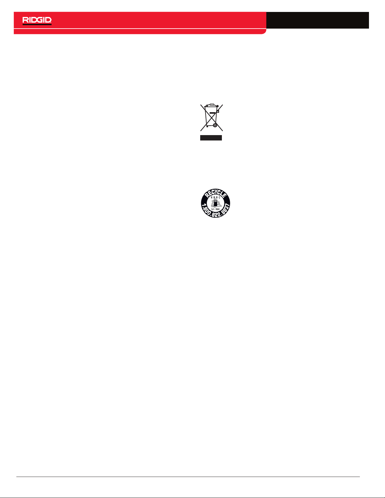
For EC countries: Do not dispose of electrical equipment with household waste!
According to the European Guideline 2002/
96/EC for Waste Electrical and Electronic
Equipment and its implementation into national legislation, electrical equipment that is no longer usable must be collected separately and disposed of in an
environmentally correct manner.
Battery Disposal
RIDGID is licensed with the Call2Recycle®
program, operated by the Rechargeable
Battery Recycling Corporation (RBRC
As a licensee, RIDGID pays the cost of recycling RIDGID rechargeable batteries.
™
).
In the USA and Canada, RIDGID and other battery suppliers use the Call2Recycle® program network of over
30,000
chargeable batteries. Return used batteries to a
col-lection location for recycling.
For EC countries: Defective or used battery packs/
batteries must be recycled according to the guideline
2006/66/EC.
collection locations to collect and recycle re-
32 – English – CS6
Page 33
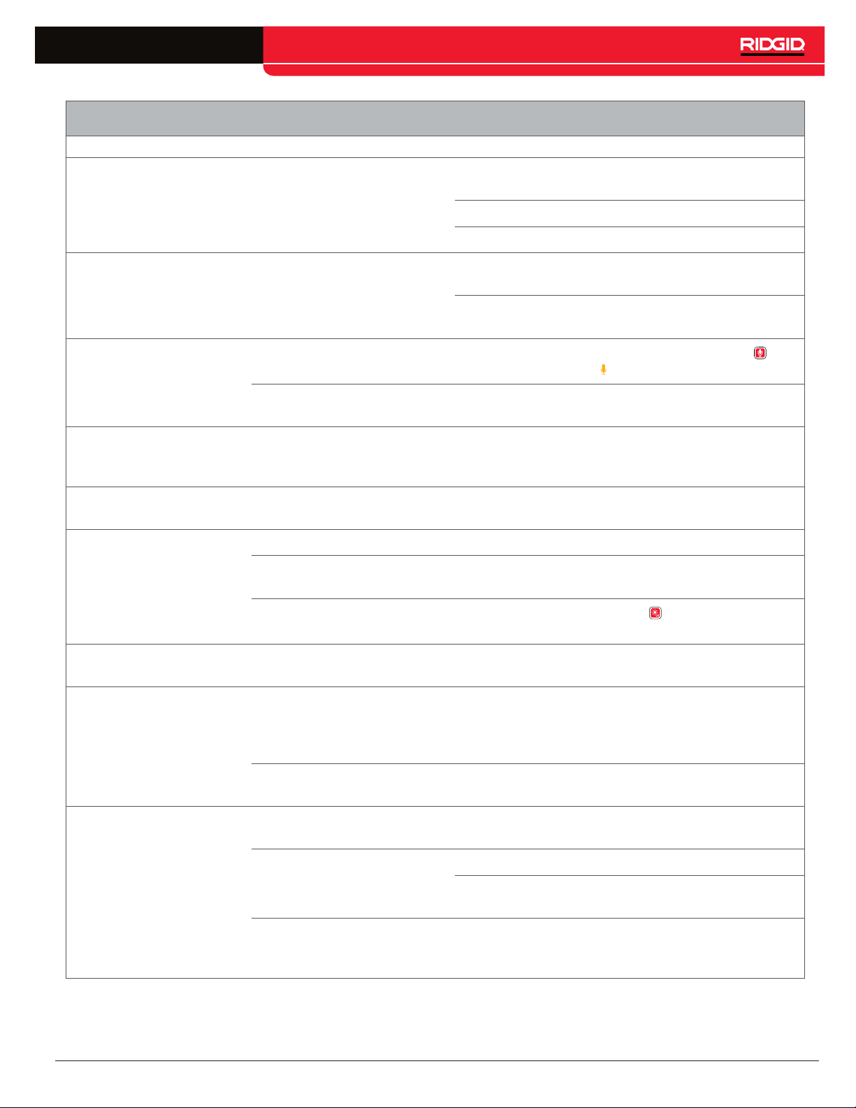
Troubleshooting
Problem Probable Fault Solution
Verify that the battery is a compatible model. Not all
System does not power
on
Unable to capture media No USB drive inserted
Power source
batteries that fit into the battery shoe are compatible.
Recharge the battery.
Switch to AC power.
Insert a USB drive. A USB drive must be inserted to
capture media.
Verify the USB drive you are using is working and not
corrupted or read-only.
Speakers are muted
No audio during playback
Settings need adjustment
Broken file warning
appears after inserting
the USB drive
Job Manager is empty No USB drive inserted
The display is dark or
hard to see
Low battery warning
appears
Count measurement
accuracy is unreliable
USB drive was removed
before data was fully written,
files may be corrupted
Glare on the display Position the display facing away from direct sunlight.
LCD settings
Camera LED settings
Low battery
The drum’s integrated
counter settings are
incorrect for the drum or
push cable
Counting from the wrong
zero point
Verify the LED below the Microphone Mute key is lit
and the icon is yellow .
Go to the settings tab to adjust the speaker volume
and microphone gain settings.
Select the repair option when prompted to attempt a
file recovery.
Insert a USB drive. Job data is stored on the USB
drive only. The CS6 does not have internal memory.
Go to the LCD settings tab to adjust the LCD display
settings.
Press the LED Brightness key to adjust the camera
LED brightness.
Power off to avoid data loss. Recharge the battery or
switch to AC power.
Verify the settings are correct for the cable length,
cable diameter, and drum.
Confirm measurement starts from the intended zero
point.
No live view
No power
Slip-ring assembly is
broken or there is a faulty
connection
System cable connection is
faulty
Check to make sure the battery is charged or the AC
adapter is properly connected.
Check all alignment and connection pins.
Check placement and pin condition in the slip-ring
assembly.
Check system cable connection. Make sure the
connector is pushed all the way in and the outer
locking sleeve is secure.
CS6 – English – 33
Page 34

Printed in USA
10/15/2015
742-045-529-EN-0A Rev A
© 2015 Ridge Tool Company. All rights reserved.
Test Equipment Depot - 800.517.8431 - 99 Washington Street Melrose, MA 02176
TestEquipmentDepot.com
 Loading...