

RIDGID R8651 Operator's Manual

OPERATOR’S MANUAL
6-1/2 in. 18 V
CIRCULAR SAW
MANUEL D’UTILISATION
165 mm (6-1/2 po) 18 V
SCIE CIRCULAIRE
MANUAL DEL OPERADOR
165 mm (6-1/2 pulg.) 18 V
SIERRA CIRCULAR
R8651
To register your RIDGID
product, please visit:
50
45
30
http://register.RIDGID.com
Pour enregistrer votre
produit de RIDGID,
s’il vous plaît la visite:
http://register.RIDGID.com
Para registrar su producto
de RIDGID, por favor visita:
http://register.RIDGID.com
Your circular saw has been engineered and manufactured to our high standards for dependability, ease of operation, and
operator safety. When properly cared for, it will give you years of rugged, trouble-free performance.
WARNING:
To reduce the risk of injury, the user must read and understand the operator’s manual before using this product.
Thank you for buying a RIDGID® product.
SAVE THIS MANUAL FOR FUTURE REFERENCE
Cette scie circulaire a été conçue et fabriquée conformément à
nos strictes normes de fiabilité, simplicité d’emploi et sécurité
d’utilisation. Correctement entretenue, elle vous donnera des années de fonctionnement robuste et sans problèmes.
AVERTISSEMENT :
Pour réduire les risques de blessures, l’utilisateur doit
lire et veiller à bien comprendre le manuel d’utilisation
avant d’utiliser ce produit.
Esta sierra circular ha sido diseñada y fabricada de conformidad
con nuestras estrictas normas para brindar fiabilidad, facilidad de
uso y seguridad para el operador. Con el debido cuidado, el sierra
le brindará muchos años de sólido funcionamiento y sin problemas.
ADVERTENCIA:
Para reducir el riesgo de lesiones, el usuario debe leer
y comprender el manual del operador antes de usar
este producto.
Merci d’avoir acheté un produit RIDGID®.
CONSERVER CE MANUEL POUR
FUTURE RÉFÉRENCE
Le agradecemos la compra de un producto RIDGID®.
GUARDE ESTE MANUAL PARA
FUTURAS CONSULTAS
1 - English

TABLE OF CONTENTS
TABLE DES MATIÈRES / ÍNDICE DE CONTENIDO
Introduction ......................................................................................................................................................................2
Introduction / Introducción
General Power Tool Safety Warnings ............................................................................................................................3-4
Règles de sécurité relatives aux outils électriques / Advertencias de seguridad para herramientas eléctricas
Circular Saw Safety Warnings .......................................................................................................................................4-5
Avertissements de sécurité relatifs au scie circulaire / Advertencias de seguridad sierra circular
Symbols ............................................................................................................................................................................ 6
Symboles / Símbolos
Features ............................................................................................................................................................................7
Caractéristiques / Características
Assembly .......................................................................................................................................................................... 8
Assemblage / Armado
Operation .....................................................................................................................................................................9-12
Utilisation / Funcionamiento
Adjustments .................................................................................................................................................................... 12
Réglages / Ajustes
Maintenance ................................................................................................................................................................... 13
Entretien / Mantenimiento
Accessories .................................................................................................................................................................... 13
Accessoires / Accesorios
Warranty .........................................................................................................................................................................14
Garantie / Garantía
Figure numbers (illustrations) ....................................................................................................................................15-18
Figure numéros (illustrations) / Figura numeras (ilustraciones)
Parts Ordering and Service ...............................................................................................................................Back Page
Commande de pièces et réparation / Pedidos de piezas y servicio ......................................................... Page arrière / Pág. posterior
INTRODUCTION
INTRODUCTION / INTRODUCCIÓN
This product has many features for making its use more pleasant and enjoyable. Safety, performance, and dependability
have been given top priority in the design of this product making it easy to maintain and operate.
* * *
Ce produit offre de nombreuses fonctions destinées à rendre son utilisation plus plaisante et satisfaisante. Lors de la
conception de ce produit, l’accent a été mis sur la sécurité, les performances et la fiabilité, afin d’en faire un outil facile à
utiliser et à entretenir.
* * *
Este producto ofrece numerosas características para hacer más agradable y placentero su uso. En el diseño de este producto
se ha conferido prioridad a la seguridad, el desempeño y la fiabilidad, por lo cual se facilita su manejo y mantenimiento.
2 - English

GENERAL POWER TOOL SAFETY WARNINGS
Use personal protective equipment. Always wear eye
WARNING
Read all safety warnings and all instructions.
Failure to follow the warnings and instructions may
result in electric shock, fire and/or serious injury.
Save all warnings and instructions for future reference.
The term “power tool” in the warnings refers to your mainsoperated (corded) power tool or battery-operated (cordless)
power tool.
WORK AREA SAFETY
Keep work area clean and well lit. Cluttered or dark
areas invite accidents.
Do not operate power tools in explosive atmospheres,
such as in the presence of flammable liquids, gases
or dust. Power tools create sparks which may ignite the
dust or fumes.
Keep children and bystanders away while operating a
power tool. Distractions can cause you to lose control.
ELECTRICAL SAFETY
Power tool plugs must match the outlet. Never modify
the plug in any way. Do not use any adapter plugs with
earthed (grounded) power tools. Unmodified plugs and
matching outlets will reduce risk of electric shock.
Avoid body contact with earthed or grounded surfaces
such as pipes, radiators, ranges and refrigerators.
There is an increased risk of electric shock if your body
is earthed or grounded.
Do not expose power tools to rain or wet conditions.
Water entering a power tool will increase the risk of electric shock.
Do not abuse the cord. Never use the cord for carrying,
pulling or unplugging the power tool. Keep cord away
from heat, oil, sharp edges or moving parts. Damaged
or entangled cords increase the risk of electric shock.
When operating a power tool outdoors, use an exten-
sion cord suitable for outdoor use. Use of a cord suit-
able for outdoor use reduces the risk of electric shock.
If operating a power tool in a damp location is un-
avoidable, use a ground fault circuit interrupter (GFCI)
protected supply. Use of a GFCI reduces the risk of
electric shock.
For use only with 18 V nickel-cadmium and 18 V
lithium-ion battery packs, see tool/appliance/battery
pack/charger correlation supplement 988000-302.
PERSONAL SAFETY
Stay alert, watch what you are doing and use com-
mon sense when operating a power tool. Do not use a
power tool while you are tired or under the influence of
drugs, alcohol or medication. A moment of inattention
while operating power tools may result in serious personal
injury.
protection. Protective equipment such as dust mask, nonskid safety shoes, hard hat, or hearing protection used for
appropriate conditions will reduce personal injuries.
Prevent unintentional starting. Ensure the switch is in
the off-position before connecting to power source
and/or battery pack, picking up or carrying the tool.
Carrying power tools with your finger on the switch or
energising power tools that have the switch on invites
accidents.
Remove any adjusting key or wrench before turning
the power tool on. A wrench or a key left attached to a
rotating part of the power tool may result in personal injury.
Do not overreach. Keep proper footing and balance at
all times. This enables better control of the power tool in
unexpected situations.
Dress properly. Do not wear loose clothing or jewellery.
Keep your hair, clothing and gloves away from moving
parts. Loose clothes, jewellery or long hair can be caught
in moving parts.
If devices are provided for the connection of dust
extraction and collection facilities, ensure these are
connected and properly used. Use of dust collection
can reduce dust-related hazards.
Do not wear loose clothing or jewelry. Contain long
hair. Loose clothes, jewelry, or long hair can be drawn into
air vents.
Do not use on a ladder or unstable support. Stable footing on a solid surface enables better control of the power
tool in unexpected situations.
POWER TOOL USE AND CARE
Do not force the power tool. Use the correct power
tool for your application. The correct power tool will
do the job better and safer at the rate for which it was
designed.
Do not use the power tool if the switch does not turn
it on and off. Any power tool that cannot be controlled
with the switch is dangerous and must be repaired.
Disconnect the plug from the power source and/or
the battery pack from the power tool before making
any adjustments, changing accessories, or storing
power tools. Such preventive safety measures reduce
the risk of starting the power tool accidentally.
Store idle power tools out of the reach of children and
do not allow persons unfamiliar with the power tool
or these instructions to operate the power tool. Power
tools are dangerous in the hands of untrained users.
Maintain power tools. Check for misalignment or
binding of moving parts, breakage of parts and any
other condition that may affect the power tool’s
operation. If damaged, have the power tool repaired
before use. Many accidents are caused by poorly
maintained power tools.
3 - English

GENERAL POWER TOOL SAFETY WARNINGS
Keep cutting tools sharp and clean. Properly maintained
cutting tools with sharp cutting edges are less likely to
bind and are easier to control.
Use the power tool, accessories and tool bits etc.
in accordance with these instructions, taking into
account the working conditions and the work to be
performed. Use of the power tool for operations different
from those intended could result in a hazardous situation.
BATTERY TOOL USE AND CARE
Recharge only with the charger specified by the
manufacturer. A charger that is suitable for one type
of battery pack may create a risk of fire when used with
another battery pack.
Use power tools only with specifically designated
battery packs. Use of any other battery packs may create
a risk of injury and fire.
When battery pack is not in use, keep it away from
other metal objects, like paper clips, coins, keys, nails,
screws or other small metal objects, that can make a
connection from one terminal to another. Shorting the
battery terminals together may cause burns or a fire.
Under abusive conditions, liquid may be ejected from
the battery; avoid contact. If contact accidentally
occurs, flush with water. If liquid contacts eyes,
additionally seek medical help. Liquid ejected from the
battery may cause irritation or burns.
SERVICE
Have your power tool serviced by a qualified repair
person using only identical replacement parts. This will
ensure that the safety of the power tool is maintained.
When servicing a power tool, use only identical
replacement parts. Follow instructions in the
Maintenance section of this manual. Use of unauthorized
parts or failure to follow Maintenance instructions may
create a risk of shock or injury.
CIRCULAR SAW SAFETY WARNINGS
DANGER:
Keep hands away from cutting area and the
blade. Keep your second hand on auxiliary
handle, or motor housing. If both hands are
holding the saw, they cannot be cut by the blade.
Do not reach underneath the workpiece. The guard
can not protect you from the blade below the workpiece.
Adjust the cutting depth to the thickness of the
workpiece. Less than a full tooth of the blade teeth should
be visible below the workpiece.
Never hold piece being cut in your hands or across
your leg. Secure the workpiece to a stable platform.
It is important to support the work properly to minimize
body exposure, blade binding, or loss of control.
Hold power tool by insulated gripping surfaces, when
performing an operation where the cutting tool may
contact hidden wiring. Contact with a “live” wire will
also make exposed metal parts of the power tool “live”
and shock the operator.
When ripping always use a rip fence or straight edge
guide. This improves the accuracy of cut and reduces
the chance of blade binding.
Always use blades with correct size and shape
(diamond versus round) of arbour holes. Blades that
do not match the mounting hardware of the saw will run
eccentrically, causing loss of control.
Never use damaged or incorrect blade washers or
bolt. The blade washers and bolt were specially designed
for your saw, for optimum performance and safety of
operation.
CAUSES AND OPERATOR PREVENTION OF
KICKBACK
Kickback is a sudden reaction to a pinched, bound, or
misaligned saw blade, causing an uncontrolled saw to lift
up and out of the workpiece toward the operator.
When the blade is pinched or bound tightly by the kerf
closing down, the blade stalls and the motor reaction drives
the unit rapidly back toward the operator.
If the blade becomes twisted or misaligned in the cut, the
teeth at the back edge of the blade can dig into the top
surface of the wood causing the blade to climb out of the
kerf and jump back toward the operator.
Kickback is the result of saw misuse and/or incorrect
operating procedures or conditions and can be avoided by
taking proper precautions as given below:
Maintain a firm grip with both hands on the saw and
position your arms to resist kickback forces. Position
your body to either side of the blade, but not in line
with the blade. Kickback could cause the saw to jump
backwards, but kickback forces can be controlled by the
operator, if proper precautions are taken.
4 - English

SPECIFIC SAFETY RULES
When blade is binding, or when interrupting a cut
for any reason, release the trigger and hold the saw
motionless in the material until the blade comes to a
complete stop. Never attempt to remove the saw from
the work or pull the saw backward while the blade is
in motion or kickback may occur. Investigate and take
corrective actions to eliminate the cause of blade binding.
When restarting a saw in the workpiece, centre the
saw blade in the kerf and check that saw teeth are
not engaged into the material. If saw blade is binding,
it may walk up or kickback from the workpiece as the
saw is restarted.
Support large panels to minimise the risk of blade
pinching and kickback. Large panels tend to sag under
their own weight. Supports must be placed under the
panel on both sides, near the line of cut and near the
edge of the panel.
Do not use dull or damaged blades. Unsharpened
or improperly set blades produce narrow kerf causing
excessive friction, blade binding and kickback.
Blade depth and bevel adjusting locking levers must be
tight and secure before making cut. If blade adjustment
shifts while cutting, it may cause binding and kickback.
Use extra caution when making a “plunge cut” into
existing walls or other blind areas. The protruding blade
may cut objects that can cause kickback.
Check lower guard for proper closing before each
use. Do not operate the saw if lower guard does not
move freely and close instantly. Never clamp or tie the
lower guard into the open position. If saw is accidentally
dropped, lower guard may be bent. Raise the lower guard
with the retracting handle and make sure it moves freely
and does not touch the blade or any other part, in all
angles and depths of cut.
Check the operation of the lower guard spring. If the
guard and the spring are not operating properly, they
must be serviced before use. Lower guard may operate
sluggishly due to damaged parts, gummy deposits, or a
build-up of debris.
Lower guard should be retracted manually only for
special cuts, such as “plunge cuts” and “compound
cuts.” Raise lower guard by retracting handle and as
soon as blade enters the material, the lower guard
must be released. For all other sawing, the lower guard
should operate automatically.
Always observe that the lower guard is covering the
blade before placing saw down on bench or floor. An
unprotected, coasting blade will cause the saw to walk
backwards, cutting whatever is in its path. Be aware of the
time it takes for the blade to stop after switch is released.
Use clamps or another practical way to secure and
support the workpiece to a stable platform. Holding
the work by hand or against your body leaves it unstable
and may lead to loss of control.
Wait for the cutter to stop before setting the tool down.
An exposed cutter may engage the surface leading to
possible loss of control and serious injury.
Know your power tool. Read operator’s manual care-
fully. Learn its applications and limitations, as well
as the specific potential hazards related to this tool.
Following this rule will reduce the risk of electric shock,
fire, or serious injury.
Always wear eye protection with side shields marked
to comply with ANSI Z87.1, along with hearing protection. Failure to do so could result in objects being thrown
into your eyes and other possible serious injuries.
Protect your lungs. Wear a face or dust mask if the
operation is dusty. Following this rule will reduce the risk
of serious personal injury.
Protect your hearing. Wear hearing protection during
extended periods of operation. Following this rule will
reduce the risk of serious personal injury.
Battery tools do not have to be plugged into an elec-
trical outlet; therefore, they are always in operating
condition. Be aware of possible hazards when not
using your battery tool or when changing accessories.
Following this rule will reduce the risk of electric shock,
fire, or serious personal injury.
Do not place battery tools or their batteries near
fire or heat. This will reduce the risk of explosion and
possibly injury.
Never use a battery that has been dropped or received
a sharp blow. A damaged battery is subject to explosion.
Properly dispose of a dropped or damaged battery immediately.
Batteries can explode in the presence of a source
of ignition, such as a pilot light. To reduce the risk of
serious personal injury, never use any cordless product
in the presence of open flame. An exploded battery can
propel debris and chemicals. If exposed, flush with water
immediately.
Do not charge battery tool in a damp or wet
location. Following this rule will reduce the risk of electric
shock.
For best results, your battery tool should be charged
in a location where the temperature is more than
50°F but less than 100°F. To reduce the risk of seri-
ous personal injury, do not store outside or in vehicles.
Under extreme usage or temperature conditions,
battery leakage may occur. If liquid comes in contact
with your skin, wash immediately with soap and water,
then neutralize with lemon juice or vinegar. If liquid
gets into your eyes, flush them with clean water for
at least 10 minutes, then seek immediate medical
attention. Following this rule will reduce the risk of seri-
ous personal injury.
Save these instructions. Refer to them frequently and
use them to instruct others who may use this tool. If you
loan someone this tool, loan them these instructions also.
5 - English
SYMBOLS
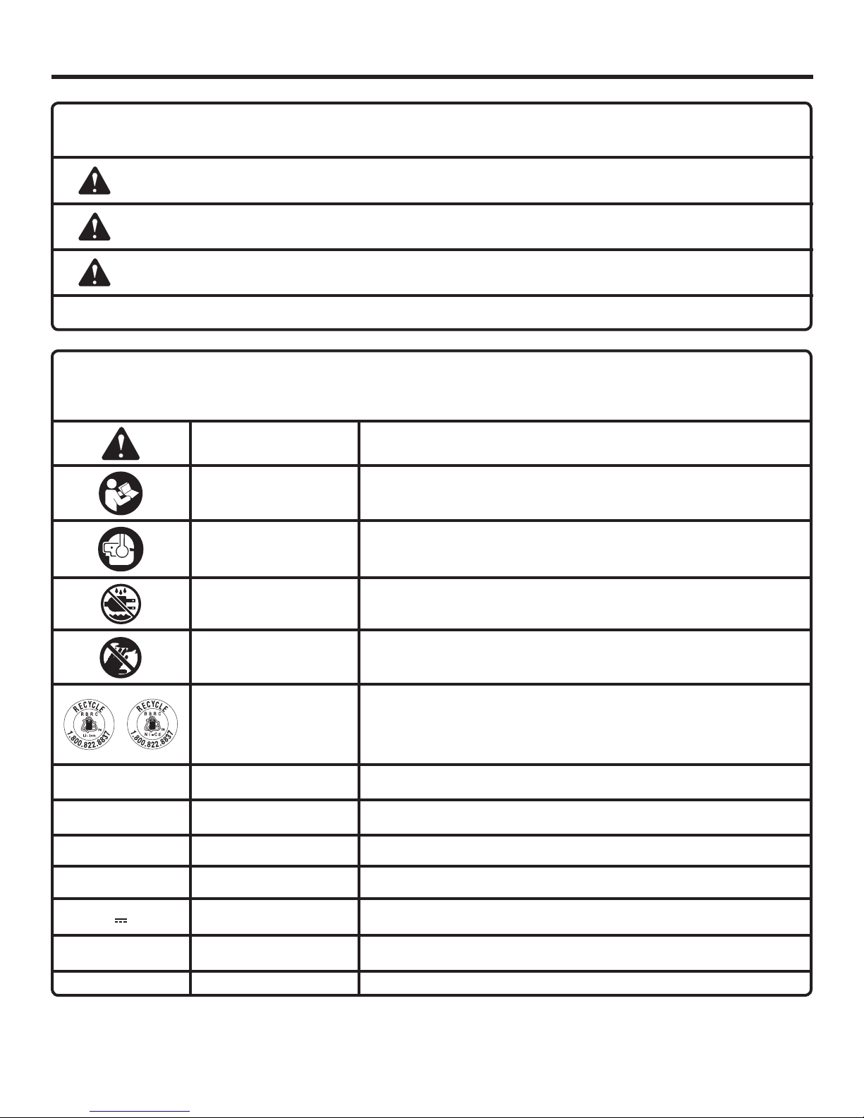
The following signal words and meanings are intended to explain the levels of risk associated with this product.
SYMBOL SIGNAL MEANING
DANGER:
WARNING:
CAUTION:
CAUTION:
Some of the following symbols may be used on this product. Please study them and learn their meaning. Proper
interpretation of these symbols will allow you to operate the product better and safer.
Indicates an imminently hazardous situation, which, if not avoided, will result in death
or serious injury.
Indicates a potentially hazardous situation, which, if not avoided, could result in death
or serious injury.
Indicates a potentially hazardous situation, which, if not avoided, may result in minor or
moderate injury.
(Without Safety Alert Symbol) Indicates a situation that may result in property damage.
SYMBOL NAME DESIGNATION/EXPLANATION
Safety Alert Indicates a potential personal injury hazard.
Read Operator’s
Manual
Eye and Hearing
Protection
To reduce the risk of injury, user must read and understand operator’s
manual before using this product.
Always wear eye protection with side shields marked to comply with
ANSI Z87.1, along with hearing protection.
Wet Conditions Alert Do not expose to rain or use in damp locations.
No Hands Symbol
Recycle Symbols
V Volts Voltage
A Amperes Current
Hz Hertz Frequency (cycles per second)
min Minutes Time
Direct Current Type or a characteristic of current
n
o
.../min Per Minute Revolutions, strokes, surface speed, orbits etc., per minute
No Load Speed Rotational speed, at no load
Failure to keep your hands away from the blade will result in serious
personal injury.
This product uses nickel- cadmium (Ni-Cd) and lithium-ion (Li-ion)
batteries. Local, state or federal laws may prohibit disposal of batteries
in ordinary trash. Consult your local waste authority for information
regarding available recycling and/or disposal options.
6 - English

FEATURES
PRODUCT SPECIFICATIONS
Blade Diameter .......................................................6-1/2 in.
Blade Arbor ............................................................... 5/8 in.
Cutting Depth at 0º .................................................2-1/8 in.
Cutting Depth at 45º ...............................................1-5/8 in.
No Load Speed .....................................5,000 r/min. (RPM)
Motor .................................................................. 18 Volt DC
KNOW YOUR CIRCULAR SAW
See Figure 1, page 15.
The safe use of this product requires an understanding of
the information on the tool and in this operator’s manual as
well as a knowledge of the project you are attempting. Before
use of this product, familiarize yourself with all operating
features and safety rules.
BEVEL ADJUSTMENT LEVER
The bevel adjustment lever allows you to set the circular saw
for bevel cuts from 0° to 50°.
NOTE: There are detentes in the bevel scale to make it easier
to set the blade angle at 45°, 30°, 22.5°, or 15°.
BLADE WRENCH STORAGE
Conveniently stores your blade wrench for quick blade
changes.
CALIFORNIA PROPOSITION 65
BLOWER PORT
The blower port clears dust and debris from the cutting area.
DEPTH ADJUSTMENT LEVER
The depth adjustment lever adjusts the depth of cut from
0 in. to 2-1/8 in.
LED LIGHT
The LED light, located on the front of the tool, illuminates
when either the switch trigger or grip light switch is depressed.
LOCK-OFF BUTTON
The lock-off button reduces the possibility of accidental
starting.
SPINDLE LOCK
The spindle lock allows you to secure the blade when turning the blade screw.
WARNING:
This product and some dust created by power sanding, sawing, grinding, drilling, and other construction activities may
contain chemicals, including lead, known to the State of California to cause cancer, birth defects, or other reproductive
harm. Wash hands after handling.
Some examples of these chemicals are:
• lead from lead-based paints,
• crystalline silica from bricks and cement and other masonry products and,
• arsenic and chromium from chemically treated lumber.
Your risk from exposure to these chemicals varies, depending on how often you do this type of work. To reduce your
exposure, work in a well-ventilated area and with approved safety equipment, such as dust masks that are specially
designed to filter out microscopic particles.
7 - English

ASSEMBLY
UNPACKING
This product requires assembly.
Carefully remove the tool and any accessories from the
box. Make sure that all items listed in the packing list are
included.
WARNING:
Do not use this product if any parts on the Packing
List are already assembled to your product when
you unpack it. Parts on this list are not assembled
to the product by the manufacturer and require
customer installation. Use of a product that may
have been improperly assembled could result in
serious personal injury.
WARNING:
A 6-1/2 in. blade is the maximum blade capacity of
the saw. Never use a blade that is too thick to allow
outer blade washer to engage with the flats on the
spindle. Larger blades will come in contact with the
blade guard, while thicker blades will prevent blade
screw from securing blade on spindle. Either of
these situations could result in a serious accident.
CAUTION:
To prevent damage to the spindle or spindle lock,
always allow motor to come to a complete stop
before engaging spindle lock.
Inspect the tool carefully to make sure no breakage or
damage occurred during shipping.
Do not discard the packing material until you have care-
fully inspected and satisfactorily operated the tool.
If any parts are damaged or missing, please call
1-866-539-1710 for assistance.
PACKING LIST
6-1/2 in. Circular Saw
Blade
5 mm Blade Wrench
Operator’s Manual
WARNING:
If any parts are damaged or missing do not operate
this product until the parts are replaced. Use of
this product with damaged or missing parts could
result in serious personal injury.
WARNING:
Do not attempt to modify this product or create
accessories not recommended for use with this
product. Any such alteration or modification is
misuse and could result in a hazardous condition
leading to possible serious personal injury.
ATTACHING THE BLADE
See Figure 2, page 15.
Remove the battery pack from the saw.
Depress and hold spindle lock.
Remove blade screw by turning it counterclockwise with
the provided 5 mm blade wrench, while keeping the
spindle lock depressed.
Wipe a drop of oil onto the inner blade washer and outer
blade washer where they contact the blade.
WARNING:
If inner blade washer has been removed, replace
it before placing blade on spindle. Failure to do
so could cause an accident since blade will not
tighten properly.
Raise the lower blade guard.
Fit the saw blade inside the lower blade guard and onto
the spindle.
NOTE: The saw teeth point upward at the front of the saw.
Replace the outer blade washer.
Depress spindle lock and replace blade screw.
Tighten blade screw securely by turning it clockwise with
the 5 mm blade wrench.
NOTE: Never use a blade that is too thick to allow the outer
blade washer to engage with the flats on the spindle.
WARNING:
To prevent accidental starting that could cause
serious personal injury, always remove the battery
pack from the tool when assembling parts.
REMOVING THE BLADE
See Figure 3, page 15..
Remove the battery pack from saw.
Depress and hold spindle lock.
Remove blade screw by turning it counterclockwise with
the provided 5 mm blade wrench, while keeping the
spindle lock depressed.
Remove outer blade washer.
Lift lower blade guard.
Remove blade.
8 - English

OPERATION
WARNING:
Do not allow familiarity with the tool to make you
careless. Remember that a careless fraction of a
second is sufficient to inflict severe injury.
TO REMOVE BATTERY PACK
See Figure 4, page 16.
Locate latches on side of battery pack and depress to
release battery pack from the saw.
The battery pack will disconnect in the direction to be
removed when buttons are depressed.
WARNING:
Always wear eye protection with side shields
marked to comply with ANSI Z87.1, along with
hearing protection. Failure to do so could result
in objects being thrown into your eyes and other
possible serious injuries.
APPLICATIONS
You may use this product for the purposes listed below:
Cutting all types of wood products (lumber, plywood,
paneling, composition board and hard board)
Cross cutting/Rip cutting
Bevel cutting
Pocket cutting
NOTE: The use of abrasive cut-off wheels is not recommended
for this saw.
This product will accept RIDGID 18 V lithium-ion battery
packs and RIDGID 18 V nickel-cadmium battery packs.
For complete charging instructions, refer to the Operator’s
Manual for the battery pack and charger model.
BATTERY PROTECTION FEATURES
RIDGID 18 V lithium-ion batteries are designed with features that protect the lithium-ion cells and maximize battery life. Under some operating conditions, these built-in
features may cause the battery and the tool it is powering
to act differently from nickel-cadmium batteries.
During some applications, the battery electronics may signal
the battery to shut down, and cause the tool to stop running.
To reset the battery and tool, release the trigger and resume
normal operation.
NOTE: To prevent further shut down of the battery, avoid
forcing the tool.
If releasing the trigger does not reset the battery and tool,
the battery pack is depleted. If depleted, the battery pack
will begin charging when placed on the lithium-ion charger.
TO INSTALL BATTERY PACK
See Figure 4, page 16.
Place battery pack in the saw. Align raised rib on battery
pack with the groove inside the saw.
Make sure the latches on each side of the battery pack
snap in place and battery pack is secured in the saw
before beginning operation.
WARNING:
Battery tools are always in operating condition.
Therefore, switch should always be locked when
not in use or carrying at your side.
SAW BLADES
The best of saw blades will not cut efficiently if they are not
kept clean, sharp, and properly set. Using a dull blade will
place a heavy load on the saw and increase the danger of
kickback. Keep extra blades on hand, so that sharp blades
are always available.
Gum and wood pitch hardened on blades will slow the saw
down. Use gum and pitch remover, hot water, or kerosene
to remove these accumulations. DO NOT USE GASOLINE.
BLADE GUARD SYSTEM
See Figure 5, page 16.
The lower blade guard attached to your cordless circular saw
is there for your protection and safety. It should never be
altered for any reason. If it becomes damaged or begins to
return slowly, do not operate the saw until the damage has
been repaired or replaced. Always leave guard in operating
position when using saw.
DANGER:
When sawing through work, lower blade guard
does not cover blade on the underside of work.
Since blade is exposed on underside of work, keep
hands and fingers away from cutting area. Any part
of your body coming in contact with moving blade
will result in serious injury.
WARNING:
To avoid possible serious injury, never use saw when
guard is not operating correctly. Check the guard
for correct operation before each use. The guard
is operating correctly when it moves freely, and
instantly returns to the closed position. If you drop
the saw, check the lower blade guard and bumper
for damage at all depth settings before reuse.
9 - English

OPERATION
WARNING:
Never tie the lower blade guard in a raised position.
Leaving the blade exposed could lead to serious
injury.
If at any time the lower blade guard does not snap closed,
remove the battery from the saw. Exercise the lower guard
by moving it rapidly back and forth from the full open position to the closed position several times. Normally this will
restore the guard to its normal operating condition. If it does
not correct a slow or sluggish closing lower guard, do not
use the saw. Take it to an authorized factory service center
for repair.
KICKBACK
See Figures 6 - 9, page 16.
Kickback occurs when the blade stalls rapidly and the saw
is driven back towards you. Blade stalling is caused by any
action which pinches the blade in the wood.
WARNING:
Release switch immediately if blade binds or saw
stalls. Kickback could cause you to lose control
of the saw. Loss of control can lead to serious
personal injury.
To guard against kickback, avoid dangerous practices such
as the following:
Setting blade depth incorrectly.
Sawing into knots or nails in workpiece.
Twisting the blade while making a cut.
Making a cut with a dull, gummed up, or improperly set
blade.
Supporting the workpiece incorrectly.
Forcing a cut.
Cutting warped or wet lumber.
Operating the tool incorrectly or misusing the tool.
To lessen the chance of kickback, follow these safety
practices:
Keep the blade at the correct depth setting. Less than a
full tooth of the blade teeth should be visible below the
workpiece.
Inspect the workpiece for knots or nails before cutting.
Never saw into a knot or nail.
Make straight cuts. Always use a straight edge guide
when rip cutting. This helps prevent twisting the blade.
Use clean, sharp, and properly set blades. Never make
cuts with dull blades.
Support the workpiece properly before beginning a cut.
Use steady, even pressure when making a cut. Never
force a cut.
Do not cut warped or wet lumber.
Always let the blade reach full speed before beginning a
cut.
Hold the saw firmly with both hands and keep your body
in a balanced position so as to resist the forces if kickback
should occur.
WARNING:
When using the saw, always stay alert and exercise
control. Do not remove the saw from the workpiece
while the blade is moving.
LOCK-OFF BUTTON
See Figure 10, page 16.
The lock-off button reduces the possibility of accidental
starting. The lock-off button is located on the handle above
the switch trigger. The lock-off button must be depressed
before you pull the switch trigger. The lock resets each time
the trigger is released.
NOTE: You can depress the lock-off button from either the
left or right side.
STARTING/STOPPING THE SAW
See Figure 10, page 16.
To start the saw:
Depress the lock-off button.
Depress the switch trigger.
Always let the blade reach full speed, then guide the saw
into the workpiece.
WARNING:
The blade coming in contact with the workpiece
before it reaches full speed could cause the saw to
“kickback” towards you resulting in serious injury.
To stop the saw, release the switch trigger.
After you release the switch trigger, allow the blade to come
to a complete stop. Do not remove the saw from the
workpiece while the blade is moving.
INDEXABLE LEVERS
See Figure 11, page 16.
The levers on the saw can be repositioned for the best
tightening position.
Pull the lever out from the saw and to desired position.
Push lever back into place.
ADJUSTING BLADE DEPTH
See Figure 12, page 17.
Always keep correct blade depth setting. Less than a
full tooth of the blade teeth should be visible below the
workpiece. More blade depth will increase the chance of
kickback and cause the cut to be rough.
10 - English

OPERATION
Remove the battery pack from saw.
Rotate adjustment lever away from the base.
Determine the desired depth of cut.
Hold base flat against the workpiece and raise or lower
saw until the index point or mark on the saw aligns with
the desired depth on the scale.
Rotate adjustment lever toward the base to lock into
position.
OPERATING THE SAW
See Figures 13 - 14, page 17.
It is important to understand the correct method for operating
the saw. Refer to the figures in this section to learn the correct
and incorrect ways for handling the saw.
DANGER:
When lifting the saw from the workpiece, the blade
is exposed on the underside of the saw until the
lower blade guard closes. Make sure the lower
blade guard is closed before setting the saw down.
WARNING:
To make sawing easier and safer, always maintain
proper control of the saw. Loss of control could
cause an accident resulting in possible serious
injury.
To make the best possible cut:
Hold the saw firmly with both hands.
Avoid placing your hand on the workpiece while making
a cut.
Support the workpiece so that the cut (kerf) is always to
your side.
Support the workpiece near the cut.
Clamp the workpiece securely so that the workpiece will
not move during the cut.
Always place the saw on the workpiece that is supported,
not the “cut off” piece.
Place the workpiece with the “good” side down.
Draw a guideline along the desired line of cut before
beginning your cut.
CROSS CUTTING/RIP CUTTING
See Figures 15 - 16, page 17.
When making a cross cut or rip cut, align your line of cut
with the outer blade guide notch on the saw base.
Since blade thicknesses vary, always make a trial cut in
scrap material along a guideline to determine how much, if
any, the guideline must be offset to produce an accurate cut.
NOTE: The distance from the line of cut to the guideline is
the amount you should offset the guide.
Secure the workpiece.
Clamp a straight edge to the workpiece using C-clamps.
Saw along the straight edge to achieve a straight rip cut.
NOTE: Do not bind the blade in the cut.
USING OPTIONAL EDGE GUIDE
See Figure 17, page 17.
Use an edge guide when making long or wide rip cuts with
the saw.
Remove the battery pack from the saw.
Place the edge guide (not included) through the holes in
the saw base.
Adjust the edge guide to the width needed.
Tighten the wing screw securely.
When using an edge guide, position the face of the edge
guide firmly against the edge of workpiece. This makes for
a true cut without pinching the blade. The guiding edge of
the workpiece must be straight for your cut to be straight.
Use caution to prevent the blade from binding in the cut.
BEVEL CUTTING
See Figures 18 - 20, page 17.
The angle of cut of the saw may be adjusted to any desired
setting between zero and 50°.
NOTE: When making cuts at 50°, the blade should be set
at full depth of cut.
Since blade thicknesses vary and different angles require
different settings, always make a trial cut in scrap material
along a guideline to determine how much you should offset
the guideline on the board to be cut.
When making a bevel cut, hold the saw firmly with both
hands.
Rest the front edge of the base on the workpiece. Depress
the lock-off button and squeeze the switch trigger to start
the saw. Always let the blade reach full speed, then guide
the saw into the workpiece.
WARNING:
The blade coming in contact with the workpiece
before it reaches full speed could cause saw to
“kickback” toward you resulting in serious injury.
After you complete your cut release the trigger and allow
the blade to come to a complete stop. After the blade has
stopped, lift the saw from the workpiece.
TO ADJUST BEVEL SETTING
See Figure 19, page 17.
Remove the battery pack from the saw.
Rotate adjustment lever counterclockwise until the motor
housing moves freely.
Raise the motor housing end of the saw until you reach
11 - English
OPERATION
the desired angle setting on the bevel scale (0-50°).
NOTE: There are detentes in the bevel scale to make it
easier to set the blade angle at 45°, 30°, 22.5°, or 15°.
Rotate the bevel adjustment lever clockwise until the
motor housing is securely locked in place.
WARNING:
Never extend your fingers while holding the lower
blade guard handle. Extending your fingers may
result in contact with the blade, causing serious
injury.
WARNING:
Attempting a bevel cut without having the bevel
adjustment lever securely locked in place can result
in serious injury.
POCKET CUTTING
See Figure 21, page 18.
WARNING:
Always adjust bevel setting to zero before making
a pocket cut. Attempting a pocket cut at any other
setting can result in loss of control of the saw
possibly causing serious injury.
Adjust the bevel setting to zero.
Set the blade to the correct blade depth setting.
Swing the lower blade guard up using the lower blade
guard handle.
NOTE: Always raise the lower blade guard with the handle
to avoid serious injury.
Hold the lower blade guard by the handle.
Rest the front of the base flat against the workpiece with
the rear of the handle raised so the blade does not touch
the workpiece.
DANGER:
Always check to insure that your fingers are clear
of the blade before depressing the switch trigger.
Contact with the blade will cause serious injury.
Depress the lock-off button and squeeze the switch trigger
to start the saw. Always let the blade reach full speed
then slowly lower blade into the workpiece until base is
flat against workpiece.
Guide the saw into the workpiece and make the cut.
WARNING:
Always cut in a forward direction when pocket
cutting. Cutting in the reverse direction could
cause the saw to climb up on the workpiece and
back toward you.
Release the trigger and allow the blade to come to a
complete stop.
Lift the saw from the workpiece.
Clear corners out with a hand saw or jig saw.
ADJUSTMENTS
WARNING:
Before performing any adjustment, make sure the
battery pack is removed from the saw and the
switch is in the OFF position. Failure to heed this
warning could result in serious personal injury.
POSITIVE 0° BEVEL STOP
See Figure 22, page 18.
The saw has a positive 0° bevel stop that has been factory
adjusted to assure 0° angle of the saw blade when making
90° cuts. However, misalignment can occur during shipping.
To check positive 0° bevel stop:
Remove the battery pack from the saw.
Place the saw in an upside down position on a workbench.
Move the lower blade guard out of the way so that the
saw blade is exposed.
Check the squareness of the saw blade to the base of
the saw using a combination square.
To adjust positive 0° bevel stop:
Remove the battery pack from the saw.
Rotate the bevel adjustment lever counterclockwise to
release.
Turn TORX® T-8 adjustment screw with TORX® T-8 wrench
and adjust base until it is square with the saw blade.
Securely lock the bevel adjustment lever.
WARNING:
Attempting a bevel cut without having the bevel
adjustment lever securely locked in place can
result in serious injury.
12 - English

MAINTENANCE
WARNING:
When servicing use only identical replacement
parts. Use of any other parts could create a hazard
or cause product damage.
WARNING:
Always wear eye protection with side shields
marked to comply with ANSI Z87.1, along with
hearing protection. Failure to do so could result
in objects being thrown into your eyes and other
possible serious injuries.
WARNING:
To avoid serious personal injury, always remove
the battery pack from the tool when cleaning or
performing any maintenance.
GENERAL MAINTENANCE
Avoid using solvents when cleaning plastic parts. Most
plastics are susceptible to damage from various types of
commercial solvents and may be damaged by their use. Use
clean cloths to remove dirt, dust, oil, grease, etc.
WARNING:
Do not at any time let brake fluids, gasoline,
petroleum-based products, penetrating oils, etc.,
come in contact with plastic parts. Chemicals can
damage, weaken or destroy plastic which may
result in serious personal injury.
Only the parts shown on the parts list are intended to be
repaired or replaced by the customer. All other parts should
be replaced at a RIDGID® authorized service center.
BATTERY PACK REMOVAL AND PREPARATION
FOR RECYCLING
WARNING:
Upon removal, cover the battery pack’s terminals
with heavy-duty adhesive tape. Do not attempt to
destroy or disassemble battery pack or remove
any of its components. Lithium-ion and nickelcadmium batteries must be recycled or disposed
of properly. Also, never touch both terminals with
metal objects and/or body parts as short circuit
may result. Keep away from children. Failure to
comply with these warnings could result in fire
and/or serious injury.
ACCESSORIES
Look for these accessories where you purchased this product:
Edge Guide ........................................................................................................................................................ 202050004
WARNING:
Current attachments and accessories available for use with this tool are listed above. Do not use any attachments
or accessories not recommended by the manufacturer of this tool. The use of attachments or accessories not
recommended can result in serious personal injury.
NOTE: FIGURES (ILLUSTRATIONS) START ON PAGE 15
AFTER FRENCH AND SPANISH LANGUAGE SECTIONS.
13 - English

WARRANTY
RIDGID® HAND HELD AND STATIONARY POWER TOOL
3 YEAR LIMITED SERVICE WARRANTY
Proof of purchase must be presented when requesting warranty service.
Limited to RIDGID® hand held and stationary power tools
purchased 2/1/04 and after. This product is manufactured
by One World Technologies, Inc. The trademark is licensed
from RIDGID, Inc. All warranty communications should be
directed to One World Technologies, Inc., attn: RIDGID Hand
Held and Stationary Power Tool Technical Service at (toll
free) 1-866-539-1710.
90-DAY SATISFACTION GUARANTEE POLICY
During the first 90 days after the date of purchase, if you are
dissatisfied with the performance of this RIDGID® Hand Held
and Stationary Power Tool for any reason you may return
the tool to the dealer from which it was purchased for a full
refund or exchange. To receive a replacement tool you must
present proof of purchase and return all original equipment
packaged with the original product. The replacement tool
will be covered by the limited warranty for the balance of
the 3 YEAR service warranty period.
WHAT IS COVERED UNDER THE 3 YEAR
LIMITED SERVICE WARRANTY
This warranty on RIDGID® Hand Held and Stationary Power
Tools covers all defects in workmanship or materials and normal wear items such as brushes, chucks, motors, switches,
cords, gears and even cordless batteries in this RIDGID®
tool for three years following the purchase date of the tool.
Warranties for other RIDGID® products may vary.
HOW TO OBTAIN SERVICE
To obtain service for this RIDGID® tool you must return it;
freight prepaid, or take it in to an authorized service center
for RIDGID® branded hand held and stationary power tools.
You may obtain the location of the authorized service center
nearest you by calling (toll free) 1-866-539-1710 or by logging on to the RIDGID® website at www.ridgid.com. When
requesting warranty service, you must present the original
dated sales receipt. The authorized service center will repair any faulty workmanship, and either repair or replace
any part covered under the warranty, at our option, at no
charge to you.
WHAT IS NOT COVERED
This warranty applies only to the original purchaser at retail
and may not be transferred. This warranty only covers defects arising under normal usage and does not cover any
malfunction, failure or defect resulting from misuse, abuse,
neglect, alteration, modification or repair by other than an
authorized service center for RIDGID® branded hand held
and stationary power tools. Consumable accessories provided with the tool such as, but not limited to, blades, bits
and sand paper are not covered.
RIDGID, INC. AND ONE WORLD TECHNOLOGIES, INC.
MAKE NO WARRANTIES, REPRESENTATIONS OR
PROMISES AS TO THE QUALITY OR PERFORMANCE
OF ITS POWER TOOLS OTHER THAN THOSE SPECIFICALLY STATED IN THIS WARRANTY.
ADDITIONAL LIMITATIONS
To the extent permitted by applicable law, all implied warranties, including warranties of MERCHANTABILITY or FITNESS FOR A PARTICULAR PURPOSE, are disclaimed. Any
implied warranties, including warranties of merchantability
or fitness for a particular purpose, that cannot be disclaimed
under state law are limited to three years from the date of
purchase. One World Technologies, Inc. and RIDGID, Inc.
are not responsible for direct, indirect, incidental or consequential damages. Some states do not allow limitations on
how long an implied warranty lasts and/or do not allow the
exclusion or limitation of incidental or consequential damages, so the above limitations may not apply to you. This
warranty gives you specific legal rights, and you may also
have other rights which vary from state to state.
One World Technologies, Inc.
P.O. Box 35, Hwy. 8
Pickens, SC 29671
14 - English
 Loading...