

RIDGID R861150 Operator's Manual
OPERATOR’S MANUAL
MANUEL D’UTILISATION
MANUAL DEL OPERADOR
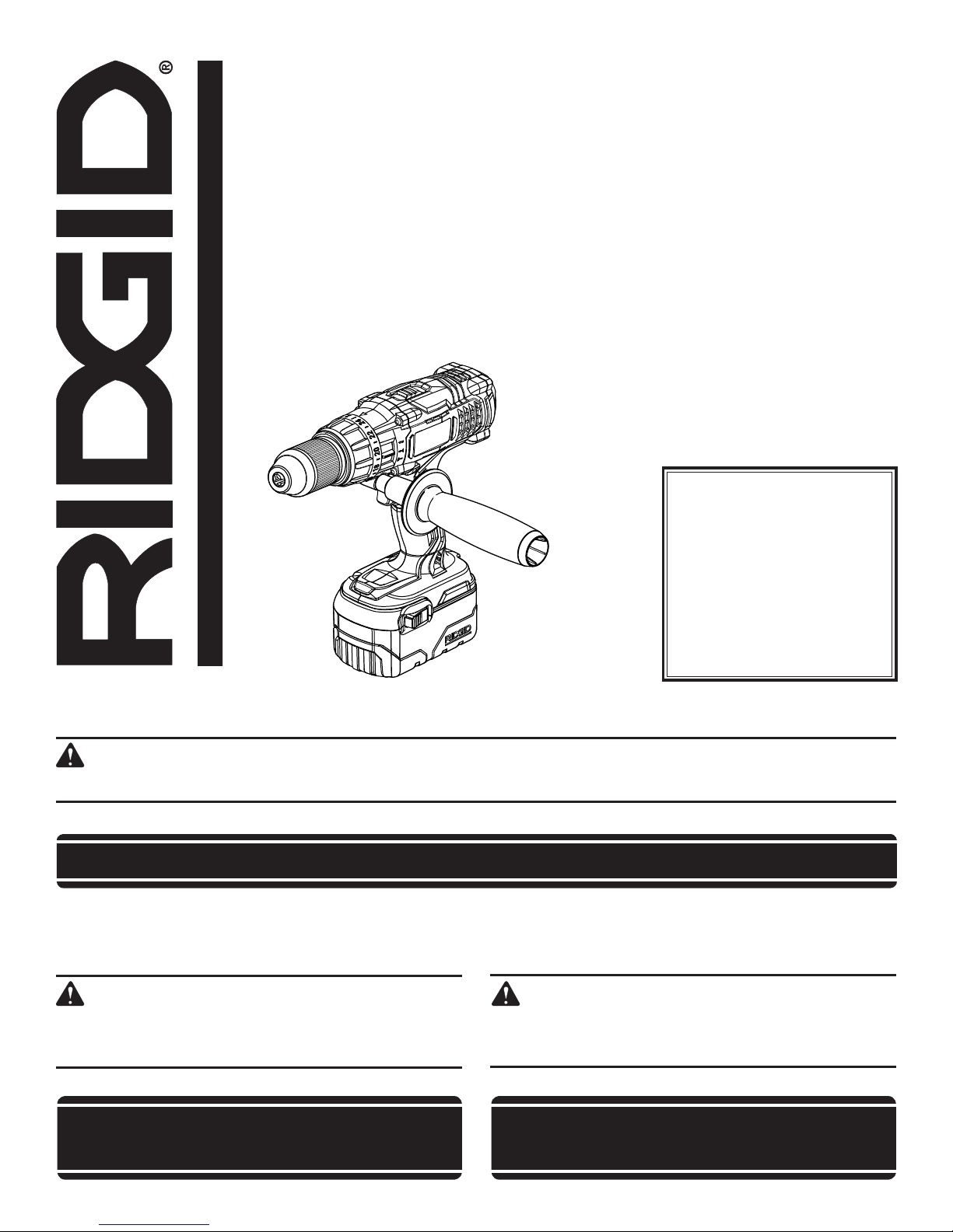
1/2 in. 18 VOLT HAMMER DRILL
TWO-SPEED/REVERSIBLE
PERCEUSE à PERCUSSION 18 V DE 13 mm (1/2 po)
2 VITESSES /RéVERSIBLE
TALADRO DE PERCUSIÓN DE 13 mm (1/2 pulg.) 18 V
DOS VELOCIDADES/INVERTIBLE
R861150
To register your RIDGID®
product, please visit:
http://register.RIDGID.com
Pour enregistrer votre
produit de RIDGID®,
s’il vous plaît la visite:
http://register.RIDGID.com
Para registrar su producto
de RIDGID®, por favor visita:
http://register.RIDGID.com
Your hammer drill has been engineered and manufactured to our high standards for dependability, ease of operation, and
operator safety. When properly cared for, it will give you years of rugged, trouble-free performance.
WARNING:
To reduce the risk of injury, the user must read and understand the operator’s manual before using this product.
Thank you for buying a RIDGID® product.
SAVE THIS MANUAL FOR FUTURE REFERENCE
Cette perceuse à percussion a été conçue et fabriquée
conformément à nos strictes normes de fiabilité, de simplicité
d’emploi et de sécurité d’utilisation. Correctement entretenue,
elle vous donnera des années de fonctionnement robuste et
sans problème.
AVERTISSEMENT :
Pour réduire les risques de blessures, l’utilisateur doit
lire et veiller à bien comprendre le manuel d’utilisation
avant d’employer ce produit.
Su taladro de percusión ha sido diseñado y fabricado de
conformidad con nuestras estrictas normas para brindar
fiabilidad, facilidad de uso y seguridad para el operador. Con el
debido cuidado, le brindará muchos años de sólido y eficiente
funcionamiento.
ADVERTENCIA:
Para reducir el riesgo de lesiones, el usuario debe leer
y comprender el manual del operador antes de usar
este producto.
Merci d’avoir acheté un produit RIDGID®.
CONSERVER CE MANUEL POUR
FUTURE RéFéRENCE
Le agradecemos la compra de un producto RIDGID®.
GUARDE ESTE MANUAL PARA
FUTURAS CONSULTAS
1 - English

TABLE OF CONTENTS
TABLE DES MATIÈRES / ÍNDICE DE CONTENIDO
Introduction ......................................................................................................................................................................2
Introduction / Introducción
General Safety Rules .....................................................................................................................................................3-4
Règles de sécurité générales / Reglas de seguridad generales
Specific Safety Rules ........................................................................................................................................................ 4
Règles de sécurité particulières / Reglas de seguridad específicas
Symbols .........................................................................................................................................................................5-6
Symboles / Símbolos
Features ............................................................................................................................................................................7
Caractéristiques / Características
Assembly ..........................................................................................................................................................................8
Assemblage / Armado
Operation .....................................................................................................................................................................8-11
Utilisation / Funcionamiento
Maintenance ................................................................................................................................................................... 12
Entretien / Mantenimiento
Warranty .........................................................................................................................................................................13
Garantie / Garantía
Figure numbers (illustrations) ....................................................................................................................................14-16
Figure numéros (illustrations) / Figura numeras (ilustraciones)
Parts Ordering and Service ...............................................................................................................................Back Page
Commande de pièces et réparation / Pedidos de piezas y servicio ......................................................... Page arrière / Pág. posterior
INTRODUCTION
INTRODUCTION / INTRODUCCIÓN
This product has many features for making its use more pleasant and enjoyable. Safety, performance, and dependability
have been given top priority in the design of this product making it easy to maintain and operate.
* * *
Ce produit offre de nombreuses fonctions destinées à rendre son utilisation plus plaisante et satisfaisante. Lors de la
conception de ce produit, l’accent a été mis sur la sécurité, les performances et la fiabilité, afin d’en faire un outil facile à
utiliser et à entretenir.
* * *
Este producto ofrece numerosas características para hacer más agradable y placentero su uso. En el diseño de este producto
se ha conferido prioridad a la seguridad, el desempeño y la fiabilidad, por lo cual se facilita su manejo y mantenimiento.
2

GENERAL SAFETY RULES
WARNING!
Read all instructions. Failure to follow all
instructions listed below may result in electric
shock, fire and/or serious injury. The term “power
tool” in all of the warnings listed below refers
to your mains-operated (corded) power tool or
battery-operated (cordless) power tool.
SAVE THESE INSTRUCTIONS
WORK AREA SAFETY
Keep work area clean and well lit. Cluttered or dark
areas invite accidents.
Do not operate power tools in explosive atmospheres,
such as in the presence of flammable liquids, gases
or dust. Power tools create sparks which may ignite the
dust or fumes.
Keep children and bystanders away while operating a
power tool. Distractions can cause you to lose control.
ELECTRICAL SAFETY
Power tool plugs must match the outlet. Never modify
the plug in any way. Do not use any adapter plugs with
earthed (grounded) power tools. Unmodified plugs and
matching outlets will reduce risk of electric shock.
Avoid body contact with earthed or grounded surfaces
such as pipes, radiators, ranges and refrigerators.
There is an increased risk of electric shock if your body
is earthed or grounded.
Do not expose power tools to rain or wet conditions.
Water entering a power tool will increase the risk of
electric shock.
Do not abuse the cord. Never use the cord for carrying,
pulling or unplugging the power tool. Keep cord away
from heat, oil, sharp edges or moving parts. Damaged
or entangled cords increase the risk of electric shock.
When operating a power tool outdoors, use an
extension cord suitable for outdoor use. Use of a
cord suitable for outdoor use reduces the risk of electric
shock.
Use battery only with charger listed.
MODEL BATTERY PACK (Li-ion)
R84008, R840084
BATTERY PACK (Ni-Cd)
R861150
130254003, 130254007
130254003, 130254007
PERSONAL SAFETY
Stay alert, watch what you are doing and use common
sense when operating a power tool. Do not use a
power tool while you are tired or under the influence of
drugs, alcohol or medication. A moment of inattention
while operating power tools may result in serious personal
injury.
CHARGER
R840091
(140276006,
140276010)
140276003
140276004
Use safety equipment. Always wear eye protection.
Safety equipment such as dust mask, non-skid safety
shoes, hard hat, or hearing protection used for appropriate
conditions will reduce personal injuries.
Avoid accidental starting. Ensure the switch is in the
off-position before plugging in. Carrying power tools
with your finger on the switch or plugging in power tools
that have the switch on invites accidents.
Remove any adjusting key or wrench before turning
the power tool on. A wrench or a key left attached to
a rotating part of the power tool may result in personal
injury.
Do not overreach. Keep proper footing and balance
at all times. This enables better control of the power tool
in unexpected situations.
Dress properly. Do not wear loose clothing or jewelry.
Keep your hair, clothing and gloves away from moving
parts. Loose clothes, jewelry or long hair can be caught
in moving parts.
If devices are provided for the connection of dust
extraction and collection facilities, ensure these are
connected and properly used. Use of these devices can
reduce dust-related hazards.
Do not wear loose clothing or jewelry. Contain long
hair. Loose clothes, jewelry, or long hair can be drawn
into air vents.
Do not use on a ladder or unstable support. Stable
footing on a solid surface enables better control of the
power tool in unexpected situations.
POWER TOOL USE AND CARE
Do not force the power tool. Use the correct power tool
for your application. The correct power tool will do the job
better and safer at the rate for which it was designed.
Do not use the power tool if the switch does not turn
it on and off. Any power tool that cannot be controlled
with the switch is dangerous and must be repaired.
Disconnect the plug from the power source and/or
the battery pack from the power tool before making
any adjustments, changing accessories, or storing
power tools. Such preventive safety measures reduce
the risk of starting the power tool accidentally.
Store idle power tools out of the reach of children and
do not allow persons unfamiliar with the power tool
or these instructions to operate the power tool. Power
tools are dangerous in the hands of untrained users.
Maintain power tools. Check for misalignment or
binding of moving parts, breakage of parts and any
other condition that may affect the power tool’s
operation. If damaged, have the power tool repaired
before use. Many accidents are caused by poorly
maintained power tools.
Keep cutting tools sharp and clean. Properly maintained
cutting tools with sharp cutting edges are less likely to
bind and are easier to control.
3 - English

GENERAL SAFETY RULES
Use the power tool, accessories and tool bits etc., in
accordance with these instructions and in the manner
intended for the particular type of power tool, taking
into account the working conditions and the work
to be performed. Use of the power tool for operations
different from those intended could result in a hazardous
situation.
BATTERY TOOL USE AND CARE
Ensure the switch is in the off position before inserting
battery pack. Inserting the battery pack into power tools
that have the switch on invites accidents.
Recharge only with the charger specified by the
manufacturer. A charger that is suitable for one type
of battery pack may create a risk of fire when used with
another battery pack.
Use power tools only with specifically designated
battery packs. Use of any other battery packs may create
a risk of injury and fire.
When battery pack is not in use, keep it away from
other metal objects like paper clips, coins, keys, nails,
screws, or other small metal objects that can make a
SPECIFIC SAFETY RULES
connection from one terminal to another. Shorting the
battery terminals together may cause burns or a fire.
Under abusive conditions, liquid may be ejected from
the battery, avoid contact. If contact accidentally
occurs, flush with water. If liquid contacts eyes,
additionally seek medical help. Liquid ejected from the
battery may cause irritation or burns.
SERVICE
Have your power tool serviced by a qualified repair
person using only identical replacement parts. This will
ensure that the safety of the power tool is maintained.
WARNING!
To reduce the risk of injury, user must read
instruction manual.
When servicing a power tool, use only identical
replacement parts. Follow instructions in the
Maintenance section of this manual. Use of unauthorized
parts or failure to follow Maintenance instructions may
create a risk of shock or injury.
Wear ear protectors with impact drills. Exposure to
noise can cause hearing loss.
Use auxiliary handles supplied with the tool. Loss of
control can cause personal injury.
Hold power tools by insulated gripping surfaces when
performing an operation where the cutting tool may
contact hidden wiring or its own cord. Contact with a
“live” wire will make exposed metal parts of the tool “live”
and shock the operator.
Know your power tool. Read operator’s manual
carefully. Learn its applications and limitations, as well
as the specific potential hazards related to this tool.
Following this rule will reduce the risk of electric shock,
fire, or serious injury.
Always wear safety glasses with side shields. Everyday
glasses have only impact resistant lenses. They are NOT
safety glasses. Following this rule will reduce the risk of
eye injury.
Protect your lungs. Wear a face or dust mask if the
operation is dusty. Following this rule will reduce the risk
of serious personal injury.
Protect your hearing. Wear hearing protection during
extended periods of operation. Following this rule will
reduce the risk of serious personal injury.
Battery tools do not have to be plugged into an
electrical outlet; therefore, they are always in
operating condition. Be aware of possible hazards
when not using your battery tool or when changing
accessories. Following this rule will reduce the risk of
electric shock, fire, or serious personal injury.
Do not place battery tools or their batteries near fire
or heat. This will reduce the risk of explosion and possibly
injury.
Do not crush, drop or damage battery pack. Do not
use a battery pack or charger that has been dropped
or received a sharp blow. A damaged battery is subject
to explosion. Properly dispose of a dropped or damaged
battery immediately.
Batteries can explode in the presence of a source
of ignition, such as a pilot light. To reduce the risk of
serious personal injury, never use any cordless product
in the presence of open flame. An exploded battery can
propel debris and chemicals. If exposed, flush with water
immediately.
Do not charge battery tool in a damp or wet location.
Following this rule will reduce the risk of electric shock.
For best results, your battery tool should be charged
in a location where the temperature is more than
50°F but less than 100°F. To reduce the risk of serious
personal injury, do not store outside or in vehicles.
Under extreme usage or temperature conditions,
battery leakage may occur. If liquid comes in contact
with your skin, wash immediately with soap and water,
then neutralize with lemon juice or vinegar. If liquid
gets into your eyes, flush them with clean water for
at least 10 minutes, then seek immediate medical
attention. Following this rule will reduce the risk of serious
personal injury.
Save these instructions. Refer to them frequently and
use them to instruct others who may use this tool. If you
loan someone this tool, loan them these instructions also
to prevent misuse of the product and possible injury.
4 - English
SYMBOLS
Li - Ion
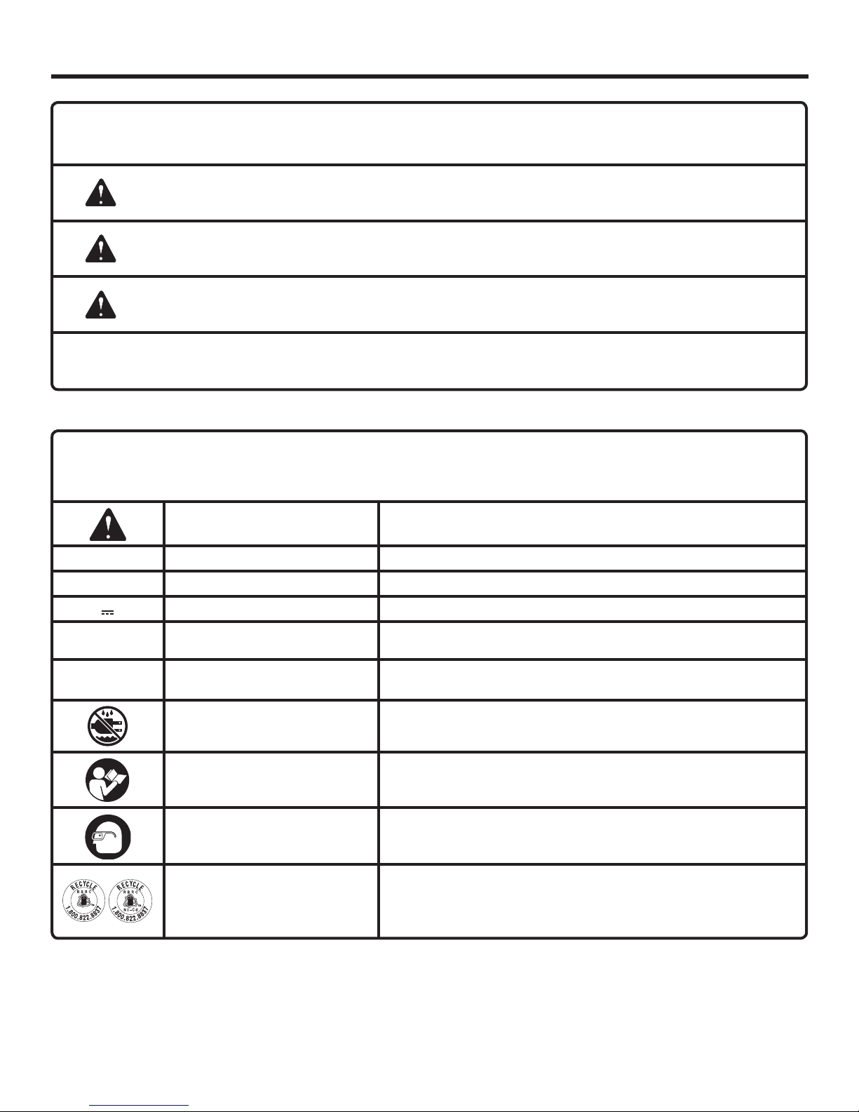
The following signal words and meanings are intended to explain the levels of risk associated with this product.
SYMBOL SIGNAL MEANING
DANGER:
WARNING:
CAUTION:
CAUTION:
Some of the following symbols may be used on this product. Please study them and learn their meaning. Proper
interpretation of these symbols will allow you to operate the product better and safer.
SYMBOL NAME
Safety Alert Indicates a potential personal injury hazard.
V Volts Voltage
min Minutes Time
Indicates an imminently hazardous situation, which, if not avoided, will result
in death or serious injury.
Indicates a potentially hazardous situation, which, if not avoided, could result
in death or serious injury.
Indicates a potentially hazardous situation, which, if not avoided, may result in
minor or moderate injury.
(Without Safety Alert Symbol) Indicates a situation that may result in property
damage.
DESIGNATION/EXPLANATION
Direct Current Type or a characteristic of current
n
o
.../min Per Minute Revolutions, strokes, surface speed, orbits etc., per minute
No Load Speed Rotational speed, at no load
Wet Conditions Alert Do not expose to rain or use in damp locations.
Read The Operator’s Manual
Eye Protection
Recycle Symbols
To reduce the risk of injury, user must read and understand
operator’s manual before using this product.
Always wear safety goggles or safety glasses with side shields and,
as necessary, a full face shield when operating this product.
This product uses lithium-ion or nickel-cadmium batteries. Local,
state or federal laws may prohibit disposal of batteries in ordinary
trash. Consult your local waste authority for information regarding
available recycling and/or disposal options.
5 - English

SYMBOLS
SERVICE
Servicing requires extreme care and knowledge and should
be performed only by a qualified service technician. For
service we suggest you return the product to your nearest
AUTHORIZED SERVICE CENTER for repair. When servicing, use only identical replacement parts.
WARNING:
The operation of any power tool can result in foreign objects being thrown into your eyes, which can result
in severe eye damage. Before beginning power tool operation, always wear safety goggles or safety glasses
with side shields and, when needed, a full face shield. We recommend Wide Vision Safety Mask for use
over eyeglasses or standard safety glasses with side shields. Always use eye protection which is marked
to comply with ANSI Z87.1.
SAVE THESE INSTRUCTIONS
WARNING:
To avoid serious personal injury, do not attempt
to use this product until you read thoroughly and
understand completely the operator’s manual.
If you do not understand the warnings and
instructions in the operator’s manual, do not use
this product. Call RIDGID® customer service for
assistance.
WARNING:
Some dust created by power sanding, sawing, grinding, drilling, and other construction activities contains chemicals
known to cause cancer, birth defects or other reproductive harm. Some examples of these chemicals are:
• lead from lead-based paints,
• crystalline silica from bricks and cement and other masonry products, and
• arsenic and chromium from chemically-treated lumber.
Your risk from these exposures varies, depending on how often you do this type of work. To reduce your exposure
to these chemicals: work in a well ventilated area, and work with approved safety equipment, such as those dust
masks that are specially designed to filter out microscopic particles.
6 - English

FEATURES
PRODUCT SPECIFICATIONS
Chuck ...........................................................1/2 in. Keyless
Motor ..................................................................18 Volt DC
Switch ................................................ Variable Speed (VSR)
No Load Speed ....................... 0-450/0-1,600 r/min. (RPM)
Blows per minute ........................... 0-7,200/0-25,600 BPM
Clutch ................................................................ 24 Position
Torque ................................................................... 565 in.lb.
KNOW YOUR HAMMER DRILL
See Figure 1, page 14.
The safe use of this product requires an understanding of the
information on the product and in this operator’s manual as
well as a knowledge of the project you are attempting. Before
use of this product, familiarize yourself with all operating
features and safety rules.
AUXILIARY HANDLE ASSEMBLY
Your drill is equipped with an auxiliary handle assembly.
For ease of operation, use the handle with either the left or
right hand.
BIT STORAGE
Bits provided with the drill can be placed in the storage area,
located on the base of the drill.
BLOWS PER MINUTE
This tool features an impact speed of 0-7,200 BPM (Blows
Per Minute) in LO speed and 0-25,600 BPM in HI speed.
Blows Per Minute is the number of impacts per minute.
DIRECTION OF ROTATION SELECTOR
(FORWARD/REVERSE/CENTER LOCK)
Your drill has a direction of rotation (forward/reverse/center
lock) selector located above the switch trigger for changing
the direction of bit rotation. Setting the switch trigger in the
OFF (center lock) position helps reduce the possibility of
accidental starting when not in use.
MODE SELECTOR
With the mode selector, you can select drill, drive, or hammer mode.
KEYLESS CHUCK
The keyless chuck allows you to hand-tighten or release the
drill bit in the chuck jaws.
LED LIGHT
The LED light, located on the front of the tool base, illuminates when the switch trigger is depressed. This provides
extra light for increased visibility.
TORQUE ADJUSTMENT RING
Your drill has a 24-position clutch. The torque adjustment
ring can be turned to select the right amount of torque for
your application.
TWO-SPEED GEAR TRAIN
The two-speed gear train is designed for drilling or driving
at LO (1) or HI (2) speeds. A slide switch is located on top
of your drill for selecting either LO (1) or HI (2) speed.
VARIABLE SPEED
The variable speed switch trigger delivers higher speed with
increased trigger pressure and lower speed with decreased
trigger pressure.
7 - English
ASSEMBLY
UNPACKING
This product has been shipped completely assembled.
Carefully remove the product and any accessories from
the box. Make sure that all items listed in the packing list
are included.
Inspect the product carefully to make sure no breakage
or damage occurred during shipping.
Do not discard the packing material until you have care-
fully inspected and satisfactorily operated the product.
If any parts are damaged or missing, please call
1-866-539-1710 for assistance.
PACKING LIST
Hammer Drill
Auxiliary Handle Assembly
Double-ended Bit
Tool Bag
Operator’s Manual
WARNING:
If any parts are damaged or missing do not operate
this product until the parts are replaced. Failure to
heed this warning could result in serious personal
injury.
WARNING:
To prevent accidental starting that could cause
serious personal injury, always remove the battery
pack from the product when assembling parts.
INSTALLING/REMOVING THE AUXILIARY
HANDLE
See Figure 2, page 14.
The drill is equipped with an auxiliary handle assembly that
can be mounted on either side.
To install the auxiliary handle:
Insert the hex bolt through the hole on the drill.
Thread the auxiliary handle onto the end of the bolt and
tighten the handle by turning it clockwise. Make sure the
handle is secure before beginning operation.
To remove the handle and install it on the opposite side:
Turn the handle counterclockwise to loosen and remove
the handle and hex bolt.
Insert the hex bolt through the hole on the drill. Thread
the auxiliary handle onto the end of the bolt and tighten
the handle by turning it clockwise.
WARNING:
Do not attempt to modify this product or create
accessories not recommended for use with this
product. Any such alteration or modification is
misuse and could result in a hazardous condition
leading to possible serious personal injury.
OPERATION
WARNING:
Do not allow familiarity with products to make you
careless. Remember that a careless fraction of a
second is sufficient to inflict severe injury.
WARNING:
Always wear safety goggles or safety glasses with
side shields when operating products. Failure to do
so could result in objects being thrown into your
eyes resulting in possible serious injury.
WARNING:
Do not use any attachments or accessories not
recommended by the manufacturer of this product.
The use of attachments or accessories not
recommended can result in serious personal injury.
APPLICATIONS
You may use this product for the purposes listed below:
Hammer drilling in concrete, brick, or other masonry
Drilling in wood
Drilling in ceramics, plastics, fiberglass, and laminates
Drilling in metals
Driving screws
Mixing paint
8 - English

OPERATION
This product will accept RIDGID 18 V lithium-ion battery
packs and RIDGID 18 V nickel-cadmium battery packs.
For complete charging instructions, refer to the Operator’s
Manual for the battery packs and chargers listed in the
General Safety Rules.
BATTERY PROTECTION FEATURES
RIDGID 18 V lithium-ion batteries are designed with features
that protect the lithium-ion cells and maximize battery life.
Under some operating conditions, these built-in features
may cause the battery and the tool it is powering to act
differently from nickel-cadmium batteries.
During some applications, the battery electronics may signal
the battery to shut down, and cause the tool to stop running.
To reset the battery and tool, release the trigger and resume
normal operation.
NOTE: To prevent further shut down of the battery, avoid
forcing the tool. Switching to a lower speed will also prevent
shut down.
If releasing the trigger does not reset the battery and tool,
the battery pack is depleted. If depleted, the battery pack will
begin charging when placed on the lithium-ion charger.
TO INSTALL BATTERY PACK
See Figure 3, page 14.
Lock the switch trigger on the drill by placing the direc-
tion of rotation (forward/reverse/center lock) selector in
center position.
Place battery pack in the drill. Align raised rib on battery
pack with the groove inside the drill.
Make sure the latches on each side of the battery pack
snap in place and battery pack is secured in the drill
before beginning operation.
TO REMOVE BATTERY PACK
See Figure 3, page 14.
Lock the switch trigger on the drill by placing the direction
of rotation selector in center position.
Locate latches on side of battery pack and depress to
release battery pack from the drill.
The battery pack will disconnect in the direction to be
removed when buttons are depressed.
VARIABLE SPEED
See Figure 4, page 14.
The variable speed switch trigger delivers higher speed with
increased trigger pressure and lower speed with decreased
trigger pressure.
NOTE: You might hear a whistling or ringing noise from the
switch during use. Do not be concerned; this is a normal
part of the switch function.
DIRECTION OF ROTATION SELECTOR
(FORWARD/REVERSE/CENTER LOCK)
See Figure 4, page 14.
The direction of bit rotation is reversible and is controlled
by a selector located above the switch trigger. With the drill
held in normal operating position, the direction of rotation
selector should be positioned to the left of the switch trigger
for forward drilling. The drilling direction is reversed when
the selector is to the right of the switch trigger.
Setting the switch trigger in the OFF (center lock) position
helps reduce the possibility of accidental starting when not
in use.
CAUTION:
To prevent gear damage, always allow the chuck
to come to a complete stop before changing the
direction of rotation.
To stop the drill, release the switch trigger and allow the
chuck to come to a complete stop.
NOTE: The drill will not run unless the direction of rotation
selector is pushed fully to the left or right.
Avoid running the drill at low speeds for extended periods
of time. Running at low speeds under constant usage may
cause the drill to become overheated. If this occurs, cool the
drill by running it without a load and at full speed.
KEYLESS CHUCK
See Figure 5, page 15.
The drill has a keyless chuck to tighten or release drill bits
in the chuck jaws. The arrows on the chuck indicate which
direction to rotate the chuck body in order to GRIP (tighten)
or OPEN (release) the drill bit.
WARNING:
Battery tools are always in operating condition.
Therefore, switch should always be locked when
not in use or carrying at your side.
SWITCH TRIGGER
See Figure 4, page 14.
To turn the drill ON, depress the switch trigger. To turn it
OFF, release the switch trigger.
WARNING:
Do not hold the chuck body with one hand and use
the power of the drill to tighten the chuck jaws on
the drill bit. The chuck body could slip in your hand,
or your hand could slip and come in contact with
the rotating drill bit. This could cause an accident
resulting in serious personal injury.
9 - English

OPERATION
LED LIGHT
See Figure 6, page 15.
The LED light on the foot of the drill will come on when the
switch trigger is depressed. This provides additional lighting
on the surface of the workpiece for operation in lower-light
areas.
TWO-SPEED GEAR TRAIN
See Figure 7, page 15.
The drill has a two-speed gear train designed for drilling or
driving at LO (1) or HI (2) speeds. A slide switch is located on
top of the drill to select either LO (1) or HI (2) speed. When
using drill in the LO (1) speed range, speed will decrease
and unit will have more power and torque. When using drill
in the HI (2) speed range, speed will increase and unit will
have less power and torque. Use LO (1) speed for high power
and torque applications and HI (2) speed for fast drilling or
driving applications.
NOTE: If you have difficulty changing from one gear range to
the other, turn the chuck by hand until the gears engage.
CAUTION:
Never change gears while the tool is running. Failure
to obey this caution could result in serious damage
to the drill.
ADJUSTABLE TORQUE CLUTCH
This product is equipped with an adjustable torque clutch for
driving different types of screws into different materials. The
proper setting depends on the type of material and the size
of screw you are using.
ADJUSTING TORQUE
See Figure 8, page 15.
When using the hammer drill for various driving applications,
it becomes necessary to increase or decrease the torque to
help prevent the possibility of damaging screw heads, threads,
workpiece, etc. In general, torque intensity should correspond
to the screw diameter. If the torque is too high or the screws
too small, the screws may be damaged or broken.
The torque is adjusted by rotating the torque adjustment
ring.
The torque is greater when the torque adjustment ring is set
on a higher setting. The torque is less when the torque adjustment ring is set on a lower setting.
The proper setting depends on the type of material and the
size of screw you are using.
NOTE: The torque adjustment ring only functions in drive
mode.
There are twenty-four torque indicator settings located on
the front of the drill.
Rotate the adjusting ring to the desired setting.
• 1 - 4 For driving small screws
• 5 - 8 For driving screws into soft material
• 9 - 12 For driving screws into soft and hard
materials
• 13 - 16 For driving screws into hard wood
• 17 - 24 For driving large screws
MODE SELECTOR
See Figure 9, page 15.
The mode selector allows you to quickly switch from drill
mode to drive or hammer mode.
In general, drill mode should be used for drilling and other
heavy duty applications. Drive mode should be used for
driving screws. Hammer mode should be used for hammer
drilling.
NOTE: The hammer drill has not been designed for reverse
hammering.
Use carbide-tipped bits and select hammer mode when drilling in hard materials such as brick, tile, concrete, etc.
Select drilling mode when drilling with twist drills, hole saws,
etc., in soft materials.
NOTE: When drilling in hammer mode, it is advisable to use
LO (1) Speed.
SELECTING DRILL, DRIVE, OR HAMMER
MODE
See Figure 9, page 15.
Select the option that best matches the type of bit, fastener,
and material you will be using.
Choose your application
Choose the correct speed: LO (1) or HI (2)
Choose the correct mode: drill, drive or hammer.
INSTALLING BITS
See Figure 10, page 15.
Lock the switch trigger by placing the direction of rotation
selector in the center position.
Open or close the chuck jaws to a point where the opening
is slightly larger than the bit size you intend to use. Also,
raise the front of the drill slightly to keep the bit from falling
out of the chuck jaws.
Insert the drill bit.
WARNING:
Make sure to insert the drill bit straight into the
chuck jaws. Do not insert the drill bit into the chuck
jaws at an angle then tighten, as shown in figure 11,
page 15. This could cause the drill bit to be thrown
from the drill, resulting in possible serious personal
injury or damage to the chuck.
Tighten the chuck jaws securely on the bit.
NOTE: Rotate the chuck body in the direction of the arrow
marked GRIP (tighten) to close the chuck jaws. Do not use
a wrench to tighten or loosen the chuck jaws.
REMOVING BITS
See Figure 10, page 15.
Lock the switch trigger by placing the direction of rotation
selector in the center position.
Open the chuck jaws.
NOTE: Rotate the chuck body in the direction of the arrow
marked OPEN (release) to open the chuck jaws. Do not
use a wrench to tighten or loosen the chuck jaws.
Remove the drill bit.
10 - English

OPERATION
BIT STORAGE
See Figure 12, page 15.
When not in use, the bit provided with the drill can be placed
in the storage area located on the base of the drill.
DRILLING
See Figure 13, page 16.
Check the direction of rotation selector for the correct
setting (forward or reverse).
Secure the material to be drilled in a vise or with clamps
to keep it from turning as the drill bit rotates.
Hold the drill firmly and place the bit at the point to be
drilled.
Depress the switch trigger to start the drill.
Move the drill bit into the workpiece, applying only enough
pressure to keep the bit cutting. Do not force the drill or
apply side pressure to elongate a hole. Let the tool do the
work.
WARNING:
Be prepared for binding at bit breakthrough. When
these situations occur, drill has a tendency to grab
and kick opposite to the direction of rotation and
could cause loss of control when breaking through
material. If not prepared, this loss of control can
result in possible serious injury.
When drilling hard, smooth surfaces, use a center punch
to mark the desired hole location. This will prevent the drill
bit from slipping off-center as the hole is started.
When drilling metals, use a light oil on the drill bit to keep
it from overheating. The oil will prolong the life of the bit
and increase the drilling action.
If the bit jams in the workpiece or if the drill stalls, stop the
tool immediately. Remove the bit from the workpiece and
determine the reason for jamming.
NOTE: This drill has an electric brake. When the switch
trigger is released, the chuck stops turning. When the brake
is functioning properly, sparks will be visible through the vent
slots on the housing. This is normal and is the action of the
brake.
WOOD DRILLING
For maximum performance, use high speed steel bits for
wood drilling.
Select drilling mode.
Begin drilling at a very low speed to prevent the bit from
slipping off the starting point. Increase the speed as the
drill bit bites into the material.
When drilling through holes, place a block of wood behind
the workpiece to prevent ragged or splintered edges on
the back side of the hole.
METAL DRILLING
For maximum performance, use high speed steel bits for
metal or steel drilling.
Select drilling mode.
Begin drilling at a very low speed to prevent the bit from
slipping off the starting point.
Maintain a speed and pressure which allows cutting with-
out overheating the bit. Applying too much pressure will:
• Overheat the drill;
• Wear the bearings;
• Bend or burn bits; and
• Produce off-center or irregular-shaped holes.
When drilling large holes in metal, start with a small bit,
then finish with a larger bit. Also, lubricate the bit with oil
to improve drilling action and increase bit life.
MASONRY DRILLING
For maximum performance, use carbide-tipped masonry
impact bits when drilling holes in brick, tile, concrete, etc.
Slide adjustment button on hammer drill left for hammer
mode.
Apply light pressure and medium speed for best results in
brick.
Apply additional pressure for hard materials such as
concrete.
When drilling holes in tile, practice on a scrap piece to
determine the best speed and pressure. Begin drilling at
a very low speed to prevent the bit from slipping off the
starting point.
11 - English

MAINTENANCE
WARNING:
When servicing use only identical RIDGID®
replacement parts. Use of any other parts may
create a hazard or cause product damage.
WARNING:
Always wear safety goggles or safety glasses with
side shields during power tool operation or when
blowing dust. If operation is dusty, also wear a
dust mask.
WARNING:
To avoid serious personal injury, always remove
the battery pack from the tool when cleaning or
performing any maintenance.
GENERAL MAINTENANCE
Avoid using solvents when cleaning plastic parts. Most
plastics are susceptible to damage from various types of
commercial solvents and may be damaged by their use. Use
clean cloths to remove dirt, dust, oil, grease, etc.
WARNING:
Do not at any time let brake fluids, gasoline,
petroleum-based products, penetrating oils, etc.,
come in contact with plastic parts. Chemicals can
damage, weaken or destroy plastic which may
result in serious personal injury.
Only the parts shown on the parts list are intended to be
repaired or replaced by the customer. All other parts should
be replaced at a RIDGID authorized service center.
CHUCK REMOVAL
See Figures 14 - 16, page 16.
The chuck may be removed and replaced by a new one.
Lock the switch trigger by placing the direction of rotation
selector in center position.
Insert a 5/16 in. or larger hex key into the chuck of the
drill and tighten the chuck jaws securely.
Tap the hex key sharply with a mallet in a clockwise di-
rection. This will loosen the screw in the chuck for easy
removal.
Open the chuck jaws and remove the hex key. Using a
screwdriver, remove the chuck screw by turning it in a
clockwise direction.
NOTE: The chuck screw has left hand threads.
Insert the hex key into the chuck and tighten the chuck
jaws securely. Tap sharply with a mallet in a counterclockwise direction. This will loosen the chuck on the spindle.
It can now be unscrewed by hand.
TO RETIGHTEN A LOOSE CHUCK
The chuck may become loose on the spindle and develop a
wobble. Also, the chuck screw may become loose, causing
the chuck jaws to bind and prevent them from closing.
To tighten:
Lock the switch trigger by placing the direction of rotation
selector in the center position.
Open the chuck jaws.
Insert the hex key into the chuck and tighten the chuck
jaws securely. Tap the hex key sharply with a mallet in
a clockwise direction. This will tighten the chuck on the
spindle.
Open the chuck jaws and remove the hex key.
Tighten the chuck screw.
BATTERY PACK REMOVAL AND PREPARATION
FOR RECYCLING
WARNING:
Upon removal, cover the battery pack’s terminals
with heavy-duty adhesive tape. Do not attempt to
destroy or disassemble battery pack or remove
any of its components. Lithium-ion and nickelcadmium batteries must be recycled or disposed
of properly. Also, never touch both terminals with
metal objects and/or body parts as short circuit
may result. Keep away from children. Failure to
comply with these warnings could result in fire
and/or serious injury.
NOTE: FIGURES (ILLUSTRATIONS) START ON PAGE 14
AFTER FRENCH AND SPANISH LANGUAGE SECTIONS.
12 - English
 Loading...