

RIDGID R6790 Operator's Manual
OPERATOR’S MANUAL
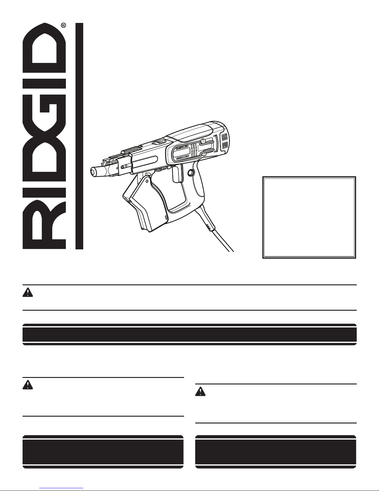
COLLATED SCREWDRIVER
DOUBLE INSULATED
MANUEL D’UTILISATION
TOURNEVIS A CHARGEUR DE VIS EN BANDE
DOUBLE ISOLATION
MANUAL DEL OPERADOR
DESTORNILLADOR PARA TORNILLOS EN TIRAS
DOBLE AISLAMIENTO
R6790
To register your RIDGID
product, please visit:
http://register.RIDGID.com
Pour enregistrer votre
produit de RIDGID,
s’il vous plaît la visite:
http://register.RIDGID.com
Para registrar su producto
de RIDGID, por favor visita:
http://register.RIDGID.com
This new screwdriver has been engineered and manufactured to our high standard for dependability, ease of operation and operator
safety. When properly cared for, the drill will give you years of rugged, trouble-free performance.
WARNING
To reduce the risk of injury, the user must read and understand the operator’s manual before using this product.
Thank you for buying a RIDGID
® product.
SAVE THIS MANUAL FOR FUTURE REFERENCE
Cet tournevis a été conçueet fabriqué conformément à nos
strictes normes de fiabilité, simplicité d’emploi et sécurité
d’utilisation. Correctement entretenu, il vous donnera des années
de fonctionnement robuste et sans problème.
AVERTISSEMENT
Pour réduire les risques de blessures, l’utilisateur doit
lire et veiller à bien comprendre le manuel d’utilisation
avant d’utiliser ce produit.
Merci d’avoir acheté un produit RIDGID
®.
CONSERVER CE MANUEL POUR
FUTURE RÉFÉRENCE
Su destornillador para paneles de yeso ha sido diseñado y
fabricado de conformidad con nuestras estrictas normas para
brindar fiabilidad, facilidad de uso y seguridad para el operador.
Con el debido cuidado, le brindará muchos años de sólido y
eficiente funcionamiento.
ADVERTENCIA
Para reducir el riesgo de lesiones, el usuario debe leer
y comprender el manual del operador antes de usar
este producto.
Le agradecemos la compra de un producto
RIDGID®.
GUARDE ESTE MANUAL PARA
FUTURAS CONSULTAS
1 - English

TABLE OF CONTENTS
TABLE DES MATIÈRES / ÍNDICE DE CONTENIDO
Introduction ......................................................................................................................................................................2
Introduction / Introducción
General Safety Rules .....................................................................................................................................................3-4
Règles de sécurité générales / Reglas de seguridad generales
Specific Safety Rules ........................................................................................................................................................4
Règles de sécurité particulières / Reglas de seguridad específicas
Symbols ............................................................................................................................................................................ 5
Symboles / Símbolos
Electrical ........................................................................................................................................................................... 6
Caractéristiques électriques / Aspectos eléctricos
Features ............................................................................................................................................................................ 7
Caractéristiques / Características
Assembly .......................................................................................................................................................................7-8
Assemblage / Armado
Operation .......................................................................................................................................................................8-9
Utilisation / Funcionamiento
Maintenance ................................................................................................................................................................... 10
Entretien / Mantenimiento
Accessories ....................................................................................................................................................................10
Accessoires / Accesorios
Troubleshooting .............................................................................................................................................................. 11
Dépannage / Solutión de problemas
Warranty .........................................................................................................................................................................12
Garantie / Garantía
Figure numbers (illustrations) ....................................................................................................................................13-14
Figure numéros (illustrations) / Figura numeras (ilustraciones)
Parts Ordering and Service ...............................................................................................................................Back Page
Commande de pièces et réparation / Pedidos de piezas y servicio ......................................................... Page arrière / Pág. posterior
INTRODUCTION
INTRODUCTION / INTRODUCCIÓN
This product has many features for making its use more pleasant and enjoyable. Safety, performance, and dependability
have been given top priority in the design of this product making it easy to maintain and operate.
Ce produit offre de nombreuses fonctions destinées à rendre son utilisation plus plaisante et satisfaisante. Lors de la
conception de ce produit, l’accent a été mis sur la sécurité, les performances et la fiabilité, afin d’en faire un outil facile à
utiliser et à entretenir.
Este producto ofrece numerosas características para hacer más agradable y placentero su uso. En el diseño de este producto
se ha conferido prioridad a la seguridad, el desempeño y la fiabilidad, por lo cual se facilita su manejo y mantenimiento.
* * *
* * *
2 - English

GENERAL SAFETY RULESGENERAL SAFETY RULES
WARNING:
Read and understand all instructions. Failure to
follow all instructions listed below, may result in
electric shock, fire and/or serious personal injury.
SAVE THESE INSTRUCTIONS
WORK AREA
Keep your work area clean and well lit. Cluttered
benches and dark areas invite accidents.
Do not operate power tools in explosive atmospheres,
such as in the presence of flammable liquids, gases,
or dust. Power tools create sparks which may ignite the
dust or fumes.
Keep bystanders, children, and visitors away while
operating a power tool. Distractions can cause you to
lose control.
ELECTRICAL SAFETY
Double insulated tools are equipped with a polarized
plug (one blade is wider than the other). This plug will
fit in a polarized outlet only one way. If the plug does
not fit fully in the outlet, reverse the plug. If it still
does not fit, contact a qualified electrician to install
a polarized outlet. Do not change the plug in any way.
Double insulation
wire grounded power cord and grounded power supply
system.
Avoid body contact with grounded surfaces such as
pipes, radiators, ranges, and refrigerators. There is an
increased risk of electric shock if your body is grounded.
Don’t expose power tools to rain or wet conditions.
Water entering a power tool will increase the risk of electric shock.
Do not abuse the cord. Never use the cord to carry the
tools or pull the plug from an outlet. Keep cord away
from heat, oil, sharp edges, or moving parts. Replace
damaged cords immediately. Damaged cords increase
the risk of electric shock.
When operating a power tool outside, use an outdoor
extension cord marked “W-A” or “W”. These cords
are rated for outdoor use and reduce the risk of electric
shock.
PERSONAL SAFETY
Stay alert, watch what you are doing and use common
sense when operating a power tool. Do not use tool
while tired or under the influence of drugs, alcohol,
or medication. A moment of inattention while operating
power tools may result in serious personal injury.
Dress properly. Do not wear loose clothing or jewelry.
Contain long hair. Keep your hair, clothing, and gloves
away from moving parts. Loose clothes, jewelry, or long
hair can be caught in moving parts.
eliminates the need for the three-
Avoid accidental starting. Be sure switch is off
before plugging in. Carrying tools with your finger on the
switch or plugging in tools that have the switch on invites
accidents.
Remove adjusting keys or wrenches before turning
the tool on. A wrench or a key that is left attached to a
rotating part of the tool may result in personal injury.
Do not overreach. Keep proper footing and balance
at all times. Proper footing and balance enables better
control of the tool in unexpected situations.
Use safety equipment. Always wear eye protection.
Dust mask, nonskid safety shoes, hard hat, or hearing
protection must be used for appropriate conditions.
Do not wear loose clothing or jewelry. Contain long
hair. Loose clothes, jewelry, or long hair can be drawn
into air vents.
Do not use on a ladder or unstable support. Stable
footing on a solid surface enables better control of the
tool in unexpected situations.
TOOL USE AND CARE
Use clamps or other practical way to secure and
support the workpiece to a stable platform. Holding
the work by hand or against your body is unstable and
may lead to loss of control.
Do not force tool. Use the correct tool for your
application. The correct tool will do the job better and
safer at the rate for which it is designed.
Do not use tool if switch does not turn it on or off. Any
tool that cannot be controlled with the switch is dangerous and must be repaired.
Disconnect the plug from power source before making
any adjustments, changing accessories, or storing the
tool. Such preventive safety measures reduce the risk of
starting the tool accidentally.
Store idle tools out of the reach of children and other
untrained persons. Tools are dangerous in the hands of
untrained users.
Maintain tools with care. Keep cutting tools sharp
and clean. Properly maintained tools with sharp cutting
edges are less likely to bind and are easier to control.
Check for misalignment or binding of moving parts,
breakage of parts, and any other condition that may
affect the tool’s operation. If damaged, have the tool
serviced before using. Many accidents are caused by
poorly maintained tools.
Use only accessories that are recommended by the
manufacturer for your model. Accessories that may be
suitable for one tool, may become hazardous when used
on another tool.
Keep the tool and its handle dry, clean and free from
oil and grease. Always use a clean cloth when clean-
ing. Never use brake fluids, gasoline, petroleum-based
products, or any strong solvents to clean your tool. Following this rule will reduce the risk of loss of control and
deterioration of the enclosure plastic.
3 - English

GENERAL SAFETY RULES
SERVICE
Tool service must be performed only by qualified
repair personnel. Service or maintenance performed by
unqualified personnel may result in a risk of injury.
WARNING:
To reduce the risk of injury, user must read
instruction manual.
SPECIFIC SAFETY RULES
Hold power tools by insulated gripping surfaces when
performing an operation where the cutting tool may
contact hidden wiring or its own cord. Contact with a
“live” wire will make exposed metal parts of the tool “live”
and shock the operator.
Know your power tool. Read operator’s manual
carefully. Learn its applications and limitations, as well
as the specific potential hazards related to this tool.
Following this rule will reduce the risk of electric shock,
fire, or serious injury.
Always wear eye protection with side shields marked
to comply with ANSI Z87.1. Following this rule will
reduce the risk of serious personal injury.
Protect your lungs. Wear a face or dust mask if the
operation is dusty. Following this rule will reduce the risk
of serious personal injury.
Protect your hearing. Wear hearing protection during
extended periods of operation. Following this rule will
reduce the risk of serious personal injury.
Inspect tool cords periodically and, if damaged, have
repaired at your nearest authorized service center.
Constantly stay aware of cord location. Following this
rule will reduce the risk of electric shock or fire.
Check damaged parts. Before further use of the
tool, a guard or other part that is damaged should
be carefully checked to determine that it will operate
properly and perform its intended function. Check for
When servicing a tool, use only identical replacement
parts. Follow instructions in the Maintenance section
of this manual. Use of unauthorized parts or failure to
follow Maintenance Instructions may create a risk of
shock or injury.
alignment of moving parts, binding of moving parts,
breakage of parts, mounting, and any other conditions
that may affect its operation. A guard or other part that
is damaged should be properly repaired or replaced
by an authorized service center. Following this rule will
reduce the risk of shock, fire, or serious injury.
Make sure your extension cord is in good condi-
tion. When using an extension cord, be sure to use
one heavy enough to carry the current your product
will draw. A wire gauge size (A.W.G.) of at least 16 is
recommended for an extension cord 50 feet or less
in length. A cord exceeding 100 feet is not recommended. If in doubt, use the next heavier gauge. The
smaller the gauge number, the heavier the cord. An
undersized cord will cause a drop in line voltage resulting
in loss of power and overheating.
Inspect for and remove all nails from lumber before
using this tool. Following this rule will reduce the risk of
serious personal injury.
If the power supply cord is damaged, it must be replaced
only by the manufacturer or by an authorized service
center to avoid risk.
Save these instructions. Refer to them frequently and
use them to instruct others who may use this tool. If you
loan someone this tool, loan them these instructions
also.
WARNING:
Some dust created by power sanding, sawing, grinding, drilling, and other construction activities contains chemicals
known to cause cancer, birth defects or other reproductive harm. Some examples of these chemicals are:
• lead from lead-based paints,
• crystalline silica from bricks and cement and other masonry products, and
• arsenic and chromium from chemically-treated lumber.
Your risk from these exposures varies, depending on how often you do this type of work. To reduce your exposure
to these chemicals: work in a well ventilated area, and work with approved safety equipment, such as those dust
masks that are specially designed to filter out microscopic particles.
4 - English
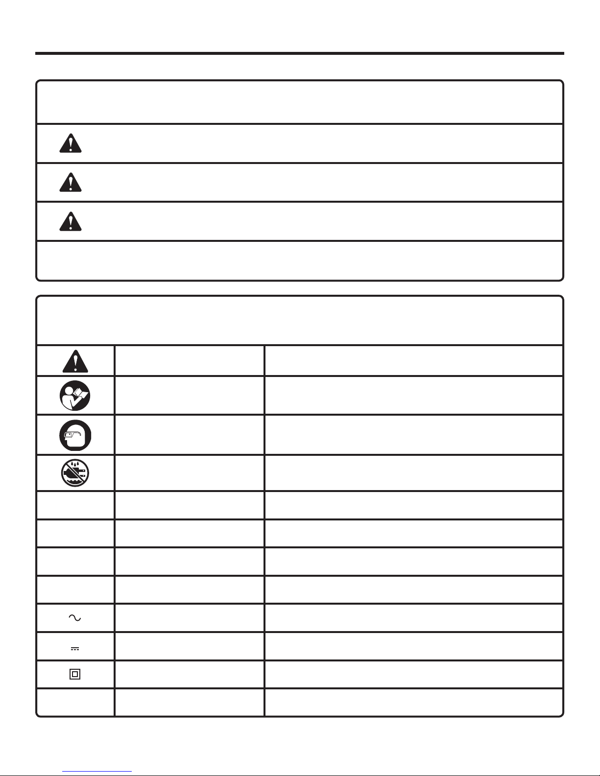
SYMBOLS
The following signal words and meanings are intended to explain the levels of risk associated with this product.
SYMBOL SIGNAL MEANING
DANGER:
WARNING:
CAUTION:
CAUTION:
Some of the following symbols may be used on this product. Please study them and learn their meaning. Proper
interpretation of these symbols will allow you to operate the product better and safer.
SYMBOL NAME
Safety Alert Indicates a potential personal injury hazard.
Read Operator’s Manual
Indicates an imminently hazardous situation, which, if not avoided, will result
in death or serious injury.
Indicates a potentially hazardous situation, which, if not avoided, could result
in death or serious injury.
Indicates a potentially hazardous situation, which, if not avoided, may result in
minor or moderate injury.
(Without Safety Alert Symbol) Indicates a situation that may result in property
damage.
DESIGNATION/EXPLANATION
To reduce the risk of injury, user must read and understand
operator’s manual before using this product.
Eye Protection
Wet Conditions Alert Do not expose to rain or use in damp locations.
V Volts Voltage
A Amperes Current
Hz Hertz Frequency (cycles per second)
W Watt Power
Alternating Current Type of current
Direct Current Type or a characteristic of current
Class II Tool Double-insulated construction
.../min Per Minute Revolutions, strokes, surface speed, orbits etc., per minute
Always wear eye protection with side shields marked to comply
with ANSI Z87.1.
5 - English
ELECTRICAL
DOUBLE INSULATION
Double insulation is a concept in safety in electric power
tools, which eliminates the need for the usual three-wire
grounded power cord. All exposed metal parts are isolated
from the internal metal motor components with protecting
insulation. Double insulated tools do not need to be
grounded.
WARNING:
The double insulated system is intended to protect
the user from shock resulting from a break in the
tool’s internal wiring. Observe all normal safety
precautions to avoid electrical shock.
NOTE: Servicing of a tool with double insulation requires
extreme care and knowledge of the system and should
be performed only by a qualified service technician. For
service, we suggest you return the tool to your nearest
authorized service center for repair. Always use original
factory replacement parts when servicing.
ELECTRICAL CONNECTION
This tool has a precision-built electric motor. It should
be connected to a power supply that is 120 V, AC only
(normal household current), 60 Hz. Do not operate this tool
on direct current (DC). A substantial voltage drop will cause
a loss of power and the motor will overheat. If the tool does
not operate when plugged into an outlet, double-check the
power supply.
EXTENSION CORDS
When using a power tool at a considerable distance from
a power source, be sure to use an extension cord that has
the capacity to handle the current the product will draw. An
undersized cord will cause a drop in line voltage, resulting in
overheating and loss of power. Use the chart to determine
the minimum wire size required in an extension cord. Only
round jacketed cords listed by Underwriter’s Laboratories
(UL) should be used.
When working outdoors with a product , use an extension
cord that is designed for outside use. This type of cord is
designated with “W-A” or “W” on the cord’s jacket.
Before using any extension cord, inspect it for loose or
exposed wires and cut or worn insulation.
**Ampere rating (on tool faceplate)
0-2.0 2.1-3.4 3.5-5.0 5.1-7.0 7.1-12.0 12.1-16.0
Cord Length Wire Size (A.W.G.)
25' 16 16 16 16 14 14
50' 16 16 16 14 14 12
100' 16 16 14 12 10 —
**Used on 12 gauge - 20 amp circuit.
NOTE: AWG = American Wire Gauge
WARNING:
Keep the extension cord clear of the working area.
Position the cord so that it will not get caught on
lumber, tools or other obstructions while you are
working with a power tool. Failure to do so can
result in serious personal injury.
WARNING:
Check extension cords before each use. If
damaged replace immediately. Never use tool with
a damaged cord since touching the damaged area
could cause electrical shock resulting in serious
injury.
6 - English

FEATURES
PRODUCT SPECIFICATIONS
Switch .......................................... Single speed/Reversible
Screw Sizes ................................................. 1 - 2 in. length
No Load Speed .................................... 3,500 r/min. (RPM)
Input ............................... 120 V, AC only, 60 Hz, 4.3 Amps
Net Weight ................................................................. 5 lbs.
KNOW YOUR COLLATED SCREWDRIVER
See Figure 1, page 14.
The safe use of this product requires an understanding of
the information on the product and in this operator’s manual
as well as a knowledge of the project you are attempting.
Before use of this product, familiarize yourself with all
operating features and safety rules.
ADJUSTABLE NOSEPIECES
Your screwdriver has an adjustable nosepiece for varying
screw depth and easy bit changes. There are two nosepieces
included, one for wood and one for drywall.
BELT CLIP
The convenient belt clip is located on the side of the motor
housing.
BIT RELEASE
The bit release makes it quick and easy to change bits
without the use of tools.
ASSEMBLY
UNPACKING
This product has been shipped completely assembled.
Carefully remove the product and any accessories from
the box. Make sure that all items listed in the packing list
are included.
WARNING:
Do not use this product if it is not completely
assembled or if any parts appear to be missing
or damaged. Use of a product that is not properly
and completely assembled could result in serious
personal injury.
Inspect the product carefully to make sure no breakage
or damage occurred during shipping.
Do not discard the packing material until you have care-
fully inspected and satisfactorily operated the product.
If any parts are damaged or missing, please call
1-866-539-1710 for assistance.
DEPTH OF DRIVE ADJUSTMENT
The drive depth can be adjusted for different applications
and workpiece thickness.
FORWARD/REVERSE SWITCH
The forward/reverse switch changes the direction of screw
rotation.
LIGHTED PLUG
This screwdriver is equipped with a plug that illuminates
when power is supplied to the tool. This allows the operator
to easily identify live tools.
LOCK-ON BUTTON
The lock-on button is convenient for continuous use for
extended periods of time.
PACKING LIST
Screwdriver
Adjustable Nosepiece (Wood)
Adjustable Nosepiece (Drywall)
5-1/8 in. Phillips Bit
Square Head Bit (2)
3/32 in. Hex Key
9/64 in. Hex Key
Nosepiece pads (3)
Tool Bag
Operator’s Manual
WARNING:
If any parts are damaged or missing do not operate
this product until the parts are replaced. Use of
this product with damaged or missing parts could
result in serious personal injury.
7 - English
ASSEMBLY
WARNING:
Do not attempt to modify this product or create
accessories not recommended for use with this
product. Any such alteration or modification is
misuse and could result in a hazardous condition
leading to possible serious personal injury.
OPERATION
WARNING:
Do not allow familiarity with products to make you
careless. Remember that a careless fraction of a
second is sufficient to inflict severe injury.
WARNING:
Always wear eye protection with side shields
marked to comply with ANSI Z87.1. Failure to do
so could result in objects being thrown into your
eyes resulting in possible serious injury.
APPLICATIONS
You may use this product for the purposes listed below:
Driving multiple screws into wood and drywall with screw-
driver bits.
TURNING THE SCREWDRIVER ON/OFF
See Figure 2, page 14.
To turn the screwdriver ON, depress the switch trigger.
Release the switch trigger to turn the screwdriver OFF.
LOCK-ON BUTTON
See Figure 2, page 14.
The screwdriver is equipped with a lock-on feature which
is convenient for continuous driving of screws for extended
periods of time. To lock-on, depress the switch trigger, push
in and hold the lock-on button located on the side of the
handle, then release switch trigger. Release the lock-on button and the screwdriver will continue running.
To release the lock, depress the switch trigger and
release.
NOTE: If you have the lock-on feature engaged during use
and the screwdriver becomes disconnected from the power
supply, disengage the lock-on feature immediately.
FORWARD/REVERSE SWITCH
See Figure 3, page 14.
The direction of rotation of the bit is controlled by a switch
located above the switch trigger. With the screwdriver held
in normal operating position, the forward/reverse switch
should be positioned to the left of the switch for forward
WARNING:
Do not connect to power supply until assembly
is complete. Failure to comply could result in
accidental starting and possible serious personal
injury.
driving operation. The direction of rotation is in reverse when
the lever is to the right of the switch.
INSTALLING BITS
See Figure 4, page 14.
Unplug the screwdriver.
Remove screw strip from the tool if previously loaded.
Hold the screwdriver upright and pull the bit release
toward the rear of the tool.
Drop the bit into the feed housing.
While still holding the bit release, depress the nosepiece
with the palm of your opposite hand to center the bit.
Cycle the nosepiece up and down while gently shaking
the tool until the bit drops into place.
NOTE: You should not be able to see the bit above the
feed housing.
Release the button when the bit drops into place.
Make sure that the bit is secure by pointing the tool
downward and shaking the tool.
If the bit is not secure, repeat the installation steps.
REMOVING BITS
See Figure 5, page 14.
Unplug the screwdriver.
Remove screw strip from tool if previously loaded.
Hold the tool with the nose pointed downward.
Pull the bit release toward the rear of the tool and shake
the tool.
Release the button when the bit drops out of the feed
housing.
SETTING SCREW LENGTH
See Figure 6, page 14.
The adjustable nosepiece allows the tool to automatically
drive screws to preset depths.
To make preset depth adjustments:
Unplug the screwdriver.
Remove the nosepiece screw by turning counterclock-
wise with the supplied 9/64 in. hex key.
8 - English

OPERATION
Slide nosepiece into the slot along the side of the feed
housing.
Align marks on the adjustable nosepiece with edge of
feed housing for proper screw length.
Reinsert and tighten the nosepiece screw by turning in
clockwise direction using supplied 9/64 in. hex key.
Make sure the nosepiece is securely attached before
operating.
CHANGING THE NOSEPIECE
See Figure 6, page 14.
Two nosepieces are included, one for wood and one for
drywall. The nosepiece can be removed and changed out by
following the instructions in “Setting Screw Length.”
LOADING COLLATED SCREWS
See Figures 7 - 8, page 15.
Before loading the screwdriver, check to be sure tops of
screws are resting on top of collated tape material as shown
in figure 7.
To load screw strip:
Unplug the screwdriver.
Adjust nosepiece to correct screw length. Follow the
instructions in “Setting Screw Length.”
Unsnap and rotate bottom of screw guard to access screw
strip guide.
Feed screw strip into the strip guide.
Move the screw strip forward into the feed housing until
the second empty hole lines up with the bit. This will allow
the screws to advance properly when the nosepiece is
depressed.
Snap the screw guard back in place.
To remove screw strip:
Unplug the screwdriver.
Pull screw strip through from the top of the feed
housing.
DEPTH OF DRIVE ADJUSTMENT
See Figure 9, page 15.
The depth of drive adjustment thumbwheel allows fine tuning
of the countersink.
Begin each new job by driving several test screws in scrap
material to check and adjust for proper countersink.
The screwdriver has a depth-sensing clutch. When the
screw is countersunk to the preset depth, it automatically
disengages and make a clicking or racheting sound. This is
normal and signals completion of the drive.
DRIVING SCREWS
See Figure 10, page 15.
Check the adjustable nosepiece for proper screw length
setting.
Check the direction of rotation selector for correct setting
(forward or reverse).
Secure the workpiece. Use clamps if necessary.
Plug the screwdriver into power supply source.
Hold the screwdriver firmly. For best results, keep the
screwdriver at a right angle to the work surface.
Depress the switch trigger to start the screwdriver. Press
the nosepiece, with constant force, against the work
surface. Do not remove the tool from the work surface
until the clutch disengages and the bit stops rotating,
signaling a fully driven screw.
Check depth of drive adjustment for proper countersink.
Adjust if necessary.
You may keep the switch trigger depressed so the next
screw will be automatically fed into place when the tool
is depressed against the work surface.
9 - English

MAINTENANCE
WARNING:
When servicing use only identical RIDGID®
replacement parts. Use of any other parts may
create a hazard or cause product damage.
WARNING:
Always wear eye protection with side shields
marked to comply with ANSI Z87.1. Failure to do
so could result in objects being thrown into your
eyes resulting in possible serious injury.
GENERAL MAINTENANCE
Avoid using solvents when cleaning plastic parts. Most
plastics are susceptible to damage from various types of
commercial solvents and may be damaged by their use. Use
clean cloths to remove dirt, dust, oil, grease, etc.
WARNING:
Do not at any time let brake fluids, gasoline,
petroleum-based products, penetrating oils, etc.,
come in contact with plastic parts. Chemicals can
damage, weaken or destroy plastic which may
result in serious personal injury.
Electric tools used on fiberglass material, wallboard, spackling compounds, or plaster are subject to accelerated wear
and possible premature failure because the fiberglass chips
and grindings are highly abrasive to bearings, brushes,
commutators, etc. Consequently, we do not recommend
using this product for extended work on these types
of materials. However, if you do work with any of these
materials, it is extremely important to clean the product
using compressed air.
LUBRICATION
All of the bearings in this product are lubricated with a sufficient amount of high grade lubricant for the life of the unit
under normal operating conditions. Therefore, no further
lubrication is required.
REPLACING THE NOSEPIECE PAD
The pad on the end of the nosepiece for wood will wear with
continued use. To replace the nosepiece:
Unplug the screwdriver. Remove the existing pad and clean
the nosepiece to remove all residue. Remove the adhesive
backing from a new pad and firmly press to secure.
ACCESSORIES
Look for these accessories where you purchased this product:
Phillips bit ............................................................................................................................................................AC96501
Square head bit ...................................................................................................................................................AC96502
WARNING:
Current attachments and accessories available for use with this tool are listed above. Do not use any attachments
or accessories not recommended by the manufacturer of this tool. The use of attachments or accessories not
recommended can result in serious personal injury.
NOTE: FIGURES (ILLUSTRATIONS) START ON PAGE 13 AFTER
FRENCH AND SPANISH LANGUAGE SECTIONS.
10 - English

TROUBLESHOOTING
PROBLEM
Motor starts slowly or fails to come
to full speed.
Tool does not drive screw into
material
Tool does not complete drive
Screws do not advance
Screws fall out during application
CAUSE
Starting switch not operating
Voltage too low to permit motor to
reach operating speed
Fuses or circuit breakers do not have
sufficient capacity
Bit is worn
Overloaded motor
Depth of drive improperly set
Bit is clogged or worn
Screw length not set correctly
Screw length not set correctly
Bit track is damaged or worn
SOLUTION
Have switch replaced.
Request voltage check from the power
company.
Install proper size fuses or circuit breakers
Replace the bit.
Check applications section for proper
uses
Adjust depth of drive
Clean or replace bit
Adjust according to “Setting Fastener
Length” section
Adjust according to “Setting Fastener
Length” section.
Replace slide body assembly
Bit does not install correctly
Bit slides or jumps off screw. Screw
is driven at an angle
Screw jams
Slide mechanism sticks or “returns”
slowy.
Motor overheats
Bit not properly seated into bit
housing
Tool is pushed forward during drive
Tool is out of alignment
Bit track is damaged or worn
Screw length not set properly
“Nosepiece” screw loosened
Bit track is damaged or worn
Bit is damaged or worn.
Nosepiece is bent or damaged
Build up of debris in mechanism
Weak return spring
Overloaded motor
Refer to “Install Bits” section
Hold tool firmly while working
Return to authorized service center
Replace slide body assembly
Adjust according to “Setting Fastener
Length” section
Tighten nosepiece screw
Replace slide body assembly
Replace bit
Replace nosepiece
Clean return mechanism
Replace spring
Check applications section for proper
uses
Pushing force becomes difficult
Slide body assembly is worn
11 - English
Replace slide body assembly
 Loading...