

RIDGID R4511 Operator's Manual
OPERATORS
TABLE
in
10
R4511
SAW
MANUAL
Your
newtable
operator
A
WARNING:
To
product.
Thank
you
safety
reduce
for
saw
has
When
properly
the
risk
buying
a
SAVE
been
engineered
cared
of
injury,
RIDGID®
THIS
and
manufactured
for,
it
will
the
user
must
product.
MANUAL
give
to
you
yearsofrugged,
read
and
FOR
our
high
standards
trouble-free performance.
understand
FUTURE
the
for
dependability,
operator’s
manual
REFERENCE
ease
before
operation,
of
using
and
this

TABLE
CONTENTS
OF
Introduction
General
Specific
•
Symbols
•
Electrical
Glossary
•
Features
Needed
Tools
•
Loose
Parts
Assembly
Operation
•
Adjustments
•
Maintenance
Accessories
•
Troubleshooting
•
Warranty
Ordering/Service
Parts
Safety
Safety
Terms
of
Rules
Rules
2
3-4
4-5
6-7
8-9
10
11-12
13
13-15
16-30
31-40
41-43
.44
44
45-46
47
48
INTRODUCTION
has
tool
This
dependability
many
have
features
been
for
given
making
top
priority
the
in
use
the
this
of
design
product
this
of
more
product
pleasant
making
and
it
easy
enjoyable.
to
maintain
Safety,
and
performance,
operate.
and
I
2

GENERAL
SAFETY
RULES
A
WARNING:
Read
to
in
injury.
READ
KNOW
manual
limitations
to
this
GUARD
ING
For
example,
sures.
KEEP
REMOVE
habit
are
removed
R
KEEP
invite
on
the
DO
not
use
rain.
to
KEEP
tors
distance
tool
MAKE
master
DON’T
at
the
USE
do
a
not
intended.
USE
extension
enough
undersized
ing
in
(A.W.G.)
cord
heavier
cord.
the
DRESS
neckties,
into
are
protective
and
understand
follow
all
instructions
electric
ALL
tool.
BODY
GUARDS
of
WORKAREA
accidents.
NOT
should
or
feed
RIGHT
job
THE
loss
25
moving
recommended
shock,
NSTRUCTIONS
YOUR
carefully.
AGAINST
checking
saw
USE
power
Keep
CHILDREN
from
extension
WORKSHOP
switches,
FORCE
it
was
PROPER
to
of
feet
gauge.
PROPERLY.Donot
or
POWER
well
as
CONTACT
pipes,
IN
ADJUSTING
to
from
DO
while
IN
toolsindamp
the
work
wear
work
cord
TOOL.
for
rate
TOOL.
not
cordisin
carry
the
cord
will
of
power
at
least14is
or
less
The
jewelry.
parts.
covering
hair
all
instructions.
listed
fire
and/or
TOOL.
Learn
as
ELECTRICAL
see
tool
it
is
DANGEROUS
safety
orbyremoving
which
designed
EXTENSION
good
smallerthe
Rubber
when
the
the
specific
WITH
GROUNDED
radiators,
PLACE
that
before
CLEAN.
NOT
in
area
AND
area.
while
CHILDPROOF
Don’t
current
cause
and
in
length.Ifin
They
ranges,
and
AND
KEYS
keys
turning
Cluttered
leave
operation.
or
well
VISITORS
glasses
Do
operating.
It
willdothe
was
it
force
for.
condition.
your
a
dropinline
overheating.
recommended
gauge
wear
get
can
gloves
working
to
contain
Failure
below,
saw’s
potential
SHOCK
in
and
tools
wet
lit.
not
designed.
the
Don’t
CORD.
may
result
serious
Read
ENVIRONMENTS.
starter
Use
product
loose
caught
and
outdoors.
personal
the
applications
hazards
BY
PREVENT
SURFACES.
refrigerator
working
good
WRENCHES.
adjusting
it
on.
areas
and
or
pieces
locations
AWAY.
and
be
keptasafe
let
visitors
with
padlocks
keys.
better
job
tool
or
attachment
it
use
for
Make
only
cord
a
will
voltage
A
wire
gauge
for
an
doubt,
long
number,
clothing,
and
nonskid
hair.
use
the
Also
operator’s
or
a
and
related
enclo
order.
Form
wrenches
benches
of
wood
Do
expose
All
visi
contact
and
and
safer
purpose
sure
your
heavy
draw.
An
result
size
extension
the
next
heavier
gloves,
draw
you
footwear
wear
to
ALWAYS
SHIELDS.
resistant
SECURE
•
practical.
hands
DON’T
balance
MAINTAIN
•
and
tions
DISCONNECT
servicing,
cutters,
•
AVOID
when
USE
operator’s
use
NEVER
the
contacted.
CHECK
tool,
carefully
and
of
parts,
its
be
center
USE
•
a
or
NEVER
THE
complete
PROTECT
•
the
PROTECT
during
DO
•
from
edges.
WHEN
AN
“W”.
the
ALWAYS
•
(SPLITTER)
KEEP
SUFFICIENT
and
3
WEAR
Everyday
lenses,
WORK.
safer
It’s
to
operate
OVERREACH.
at
all
TOOLS
clean
for
RECOMMENDED
of
toolistipped
a
perform
moving
operation.
properly
THE
blade
cutter
POWEfl
cutting
NOT
receptacle.
OUTDOOR
These
risk
kickback.
better
for
lubricating
when
or
etc.,
all
ACCIDENTAL
plugging
manual
improper
STAND
DAMAGED
guard
checked
its
parts,
mounting
A
repaired
to
avoid
RIGHT
or
cutter
only.
LEAVE
stop.
YOUR
operation
YOUR
extended
ABUSE
OPERATING
cords
of
electric
KEEP
IN
BLADES
SAFETY
eyeglasses
they
are
a
Use
than
tool.
times.
WITH
and
safer
and
TOOLS.
changing
tools
should
STARTING.
in
any
tool.
for
recommended
accessories
ON
TOOL.
or
the
if
PARTS.
or
other
part
to
determine
intended
binding
and
any
guard
or
or
replaced
risk
of
personal
DIRECTION
against
TOOL
RUNMNG
OFF.
Don’t
LUNGS.
is
dusty.
HEARING.
periods
CORD.
Keep
cord
POWER
A
EXTENSION
are
rated
shock.
THE
BLADE
PLACE
SET.
and
CLEAN,
Sharp
GLASSES
have
NOT
safety
glasses.
featherboardtohold
using
your
hand
and
Keep
changing
ACCESSORIES.
cutting
function.
of
other
other
the
leave
of
Never
away
proper
CARE.
performance.
When
attachments,
be
may
Serious
Before
that
thatitwill
moving
conditions
part
OF
direction
Wear
operation.
CORD
for
GUARD
in
working
blades
Keep
accessories.
not
disconnected.
Be
risk
injury
tool
is
damaged
Check
parts,
that
byanauthorized
injury.
FEED.
of
UNATTENDED.
tool
until
a
face
Wear
hearing
yank
cord
from
heat,
TOOL
MARKED
outdoor
SHARP,
Follow
in
sure
accessories.
injury.
could
is
unintentionally
further
operate
that
is
damaged
Feed
rotation
it
or
to
OUTSIDE,
use
AND
order.
AND
minimize
WITH
only
footing
use,
blades,
for
dust
oil,
SPREADER
SIDE
impact-
work
when
frees
tools
sharp
instruc
before
switch
Consult
breakage
comes
and
is
occur
use
of
should
properly
alignment
may
affect
must
service
work
of
blade
TURN
mask
protection
disconnect
and
sharp
USE
“W-A”
reduce
WITH
stalling
both
bits,
to
and
off
the
The
if
the
be
of
into
a
if
OR
GENERAL
SAFETY
RULES
KEEP
hands
or
work
not
Do
moving.
BLADE
NEVER
Normal
S
INSPECT
have
aged,
authorized
an
having
stripes
replacement
or
not
do
terminal.
live
immediately.
it
keep
S
INSPECT
replace
S
GROUND
prong
receptacle.
trical
S
CHECK
personnelifthe
understood
grounded.
S
S
ONLY
USE
extension
3-pole
NOT
DO
outlet,
electrician.
s
KEEP
GREASE.
HANDS
from
away
around
attempt
COASTS
USE
sparking
TOOL
repaired
service
outer
an
connect
equipment-grounding
the
is
Repair
Stay
away
well
EXTENSION
damaged.
if
ALL
it
plug,
WITH
orifin
CORRECT
cords
receptacles
MODIFY
the
have
TOOL
DRY,
Always
blades.
over
remove
AFTER
AN
the
of
FROM
Do
blade
the
BEING
EXPLOSIVE
motor
AWAY
or
to
IN
CORDS
qualified
a
by
facility.
surface
of
the
that
electric
the
equipment-grounding
replace
or
constantly
the
rotating
from
CORDS
TOOLS.
should
QUALIFIED
A
grounding
doubt
If
plugged
be
instructions
as
ELECTRICAL
3-prong
have
that
accept
that
plug
the
proper
outlet
CLEAN,
clean
use
a
CUTTING
reach
while
underneath
blade
when
cut
not
material
TURNED
ATMOSPHERE.
ignite
could
PERIODICALLY.
service
conductorwith
The
green
is
cordorplug
a
aware
or
with
conductor.
damaged
cord
of
blade.
PERIODICALLY
tool
equipped
is
into
three-hole
a
ELECTRICIAN
are
whether
to
the
DEVICES:
grounding
tool’s
the
provided.Ifit
installed
FROM
FREE
AND
when
cleaning.
cloth
AREA.
rotating.
is
blade
Keep
OFF.
fumes.
dam
If
technician
insulation
necessary,
is
worn
or
location
yellow
repair
If
cord
and
without
conductortoa
and
three-
with
elec
service
or
completely
not
properly
tool
is
3-wire
plugs
and
plug.
the
fit
not
will
qualified
a
by
AND
OIL
Never
what
operate
by
with
blade
or
blade
during
or
IT
an
for
Do
NOT
replaced
use
washers
maximum
ALL
NAILS.
cutting.
products,
Watch
not
TURN
blades
ADJUST
Inspect
parts
brake
use
solvents
any
STAY
you
tool
DO
ON
ALERT
are
doing
when
NOT
AND
USE
S
is
I
authorized
S
at
S
S
S
ONLY
USE
incorrect
bolts
that
capacity
BEFORE
MENTS
SURE
BE
remove
and
NEVER
size
of
ARE
TOUCH
gasoline,
fluids,
clean
to
AND
and
are
you
TOOL
OFF.
Have
service
CORRECT
holes.
defective
are
saw
your
MAKING
SECURE.
BLADE
nails
all
tired.
center.
PATH
BLADE
petroleum-based
tool.
EXERCISE
common
use
not
Do
SWITCH
IF
defective
BLADES.
use
Never
incorrect.
or
10
in.
is
CUT,
A
FREE
IS
lumber
from
or
CONTROL.
sense.
rush.
DOES
switches
Do
blade
The
(254
mm).
SURE
BE
OF
before
moving
other
not
use.
S
NEVER
PONENT
I
DO
NOT
INFLUENCE
START
IS
IN
OPERATE
TOOL
A
WHEN
CONTACT
A
DRUGS,
OF
WITH
TOOL
ROTATING
ANY
WORKPIECE.
THE
WHILE
ALCOHOL,
UNDER
OR
COM
THE
ANY
MEDICATION.
S
WHEN
Use
product
S
USE
this
in
are
Instructions
with
S
DOUBLE
tight
before
SERVICING
of
any
damage.
ONLY
manual
listed
not
accessory.
the
CHECK
and
not
connecting
only
use
parts
other
may
RECOMMENDED
addendums.
or
of
use
SETUPS.
contact
power
the
may
for
making
cause
safe
ALL
to
identical
create
replacement
a
ACCESSORIES
of
Use
risk
of
accessories
Make
with
saw
supply.
hazard
accessories
personal
are
sure
or
parts.
cause
or
listed
that
injury.
included
blade
workpiece
is
SPECIFIC
•
NEVER
THE
S
GUARD
the
towards
resultinginserious
and
S
USE
guide
S
SUPPORT
pinching
S
REMOVE
before
accident
S
ALWAYS
KICKBACK
OPERATE
LEG
AGAINST
blade
the
switch
turn
FENCE.
RIP
when
and
transporting
causing
USE
STAND
stalls
operator.
ripping.
LARGE
ALL
PAWLS
SAFETY
THE
SAW
FIRMLY
REST
KICKBACK.
rapidly
off
kickback,
FENCES
BLADE
and
It
can
personal
immediately
Always
PANELS.
always
saw.
Failure
possible
GUARD,
on
all
RULES
THE
ON
hand
Stay
blade
personal
THE
outofblade
binds
or
large
UNLESS
Kickback
workpiece
your
pull
injury.
if
useafence
minimize
To
support
AUXILIARY
AND
todoso
serious
SPREADER,
“through-sawing”
FLOOR.
occurs
driven
is
into
straight
risk
can
injury.
AND
operations.
FEET
when
blade
the
stalls.
or
blade
of
panels.
TABLES
result
ANTI-
OF
back
path
edge
in
an
Through-sawing
cuts
cross
back
blade.
S
ALWAYS
miter
operation
S
ALWAYS
ROW
workpiece
Size
narrower
be
from
stock,
come
push
4
completely
cutting.
down,
pawls
SECURE
as
NEVER
the
gauge.
USE
STOCK.
through
shape
and
than
contacting
always
close
to
blocks
for
operations
through
the
Keep
and
WORK
miter
PUSH
A
push
A
the
vary
can
workpiece
the
the
use
a
saw
the
non-through
the
blade
the
the
use
gauge.
STICK
stickisa
blade
but
saw
push
blade.
those
are
workpiece
guard
spreader
firmly
rip
instead
the
to
blade.
stick,
Use
cuts.
down,
against
fence
FOR
device
of
push
prevent
When
your
so
a
which
as
the
place
the
the
ripping
in
anti-kick
rip
the
in
in
during
RIPPING
to
used
your
using
must
stick
push
the
ripping
does
hand
featherboard
blade
over
fence
NAR
push
hands.
always
narrow
or
the
or
same
a
stick
not
and

S
NEVER
using
Always
and
S
NEVER
the
NEVER
blade
S
ALWAYS
cross
DO
during
S
NEVER
cutting.
NEVER
turning
power
S
PROVIDE
of
AVOID
by:
a)
b)
c)
d)
e)
S
IF
be
service
only
use
guide
path
or
cutting.
NOT
the
the
source.
the
saw
KICKBACKS
Keeping
Keeping
Keeping
blade
Not
releasing
way
past
Not
ripping
does
fence.
THE
POWER
replaced
center
perform
your
hands
either
the
work.
stand
or
the
of
saw
reach
behind,
cutter
with
REMOVE
USE
THE
same
rip
use
attempt
saw
OFF
ADEQUATE
table
blade
rip
fence
spreader,
guard
in
the
work
have
not
only
by
to
F
any
operation
to
the
rip
have
any
blade.
over,
either
THE
MITER
operation.
fence
free
to
and
wide
for
(work
sharp.
parallel
anti-kickback
place
the
work
saw
blade
that
straight
a
SUPPLY
the
manufacturer
avoid
risk.
ETY
“freehand”
support
fence
RIP
as
stalled
a
disconnecting
SUPPORT
or
and
CORD
or
part
of
within
or
hand
FENCE
GAUGE
cutoff
long
thrown
to
the
operating.
before
using
twisted
is
edge
or
for
saw
work
RU
L
guide
miter
fence
your
body
three
any
reason.
from
AND
gauge
blade
the
to
the
pieces.
back
saw
blade.
pawls,
it
is
pushed
push
a
to
IS
stick.
or
guide
DAMAGED,
or
by
ES
which
the
workpiece.
to
in
inches
the
saw
RIP
when
without
saw
rear
and
toward
and
all
warped
along
an
authorized
means
position
line
with
of
when
FENCE
cross
first
from
sides
you)
the
or
the
it
must
the
the
S
AVOID
POSITIONS
move
to
S
USE
this
not
tions
accessory.
I
MAKE
to
see
safe
table
S
ALWAYS
avoid
supply.
THIS
a)
b)
c)
d)
e)
t
g)
•
SAVE
frequently
someone
AWKWARD
where
into
the
cutting
ONLY
RECOMMENDED
manual
listed
operation
Wear
Use
every
all
Keep
Use
Pay
riskofkickback.
Do
Never
may
for
safe
SURE
the
work
saw.
TURN
accidental
TOOL
eye
saw
operation
through
hands
a
push
particular
not
perform
reach
THESE
and
this
or
addendums.
cause
use
THE
and
BEFORE
OFF
should
protection.
blade
sawing.
out
stick
around
INSTRUCTIONS.
usetoinstruct
tool,
sudden
a
the
of
accessories
WORK
that
SAW
starting
have
guard
for
of
the
when
attention
any
loan
OPERATIONS
slip
could
tool.
ACCESSORIES
Useofaccessories
risk
of
personal
AREA
HAS
no
obstructions
performing
before
when
reconnecting
the
following
and
spreader/riving
which
it
can
line
of
saw
required.
to
instructions
operation
over
or
freehand.
the
other
them
these
AND
cause
injury.
are
included
AMPLE
will
interfere
any
work
disconnecting
markings:
used,
be
blade.
on
saw
blade.
Refer
users.
instructions
HAND
your
hand
listed
that
Instruc
with
LIGHTING
with
using
the
it,
power
to
knife
for
including
reducing
them
to
If
loan
you
too.
in
are
the
to
WARNING:
Some
dust
created
known
cals
•
lead
from
•
crystalline
arsenic
Your
exposure
those
risk
dust
and
from
to
masks
to
cause
lead-based
silica
from
chromium
these
these
chemicals:
that
by
power
cancer,
paints,
bricks
exposures
are
sanding,
birth
and
from
chemically-treated
varies,
work
specially
sawing,
defects
cement
in
a
designed
or
other
and
depending
well
ventilated
to
grinding,
reproductive
other
masonry
lumber.
on
filter
drilling,
how
area,
out
microscopic
5
products,
often
and
and
harm.
work
other
Some
you
with
particles.
construction
examples
and
do
this
approved
activities
these
of
typeofwork.
safety
equipment,
contains
chemicals
To
reduce
chemi
such
are:
your
as

SYMBOLS
Some
of
tion
SYMBOL
V
A
Hz
W
mm
‘‘-‘
---
n0
j
of
these
the
following
symbols
Volts
Amperes
Hertz
Watt
Minutes
Alternating
Direct
No
Class
symbols
allow
will
Current
Load
II
be
may
to
you
NAME
Current
Speed
Construction
used
operate
on
this
the
Please
tool.
better
tool
Voltage
Current
Frequency
Power
Time
Type
Type
Rotational
Double-insulated
study
and
current
of
characteristic
or
a
meaning.
their
learn
and
them
safer.
DESIIGNATION/EXPLANATION
second)
(cycles
speed,
per
current
of
load
no
at
construction
Proper
interpreta
.../min
\
j
j(r7
Per
Wet
Read
E
ye
Safety
No
Hot
Minute
Conditions
Operator’s
The
ro
ec
Alert
Hands
Symbol
Surface
ion
Alert
Manual
Revolutions,
expose
not
Do
To
reduce
operator’s
full
reduce
surface.
wear
face
to
personal
Always
a
Precautions
Failure
serious
To
hot
strokes,
the
manual
safety
shield
that
keep
the
to
risk
when
involve
your
injury.
risk
rain
of
before
goggles,
of
surface
use
or
injury
using
operating
your
hands
injury
speed,
in
user
safety
safety.
away
or
damp
must
product.
this
glasses
this
from
damage,
orbits
locations.
read
product.
the
avoid
etc.,
with
blade
per
and
side
will
contact
minute
understand
shields,
result
with
or
in
any
6

SYMBOLS
The
following
SYMBOL
A
A
A
SERVICE
Servicing
be
service
AUTHORIZED
ing,
requires
performed
we
use
only
suggest
signal
WARNINGS
extreme
only
SERVICE
identical
words
and
SIGNAL
DANGER
CAUTION
CAUTION
care
byaqualified
return
you
CENTER
replacement
and
the
meanings
knowledge
service
product
for
repair.
parts.
are
intended
to
MEANING
an
Indicates
in
result
Indicates
in
result
Indicatesapotentially
result
in
(Without
property
and
should
technician.
your
When
nearest
servic-
to
imminently
death
a
potentially
death
minor
Safety
damage.
For
explain
or
serious
or
serious
or
moderate
Alert
A
of
levels
the
hazardous
injury.
hazardous
injury.
hazardous
injury.
Symbol)
Indicates
WARNING:
To
to
use
understand
If
you
instructions
this
assistance.
avoid
this
do
product.
serious
product
risk
associated
situation,
situation,
situation,
personal
completely
not
understand
in
operator’s
the
Call
RIDGID®
a
until
which,
which,
which,
situation
injury,
you
the
customer
with
this
if
not
not
if
not
if
that
do
read
thoroughly
operator’s
warnings
the
manual,
product.
avoided,
avoided,
avoided,
may
not
attempt
manual.
do
service
result
not
will
could
may
in
and
and
use
for
WARNING:
A
7=
•
The
in
with
over
to
severe
operation
side
eyeglasses
comply
eye
shields
with
of
any
damage.
and,
or
ANSI
power
tool
Before
when
standard
Z87.1.
SAVE
can
result
beginning
needed,
safety
a
glasses
THESE
in
power
face
full
foreign
with
tool
shield.
side
objects
operation,
We
shields.
being
always
recommend
Always
INSTRUCTIONS
thrown
wear
use
into
safety
Wide
eye
your
eyes,
goggles
Vision
Safety
protection
which
safety
or
Mask
which
can
is
result
glasses
for
use
marked
7
ELECTRICAL
3-pole
power
a
that
causing
Laboratories
(on
0-2.0
16
16
16
=
American
or
wires
the
Position
on
you
so
extension
replace
could
injury.
CORDS
extension
tool
an
use
tool
the
drop
a
to
determine
cord.
faceplate)
tool
2.1-3.4
-20
the
with
for
“W”
extension
an
cut
and
extension
umber,
working
are
result
can
immediately.
cord
cause
receptacles
extension
in
the
Only
16
16
16
amp
Wire
tool
outside
on
the
cords
EXTENSION
only
Use
ing
When
power
the
cord
power
provided
in
Underwriters
**Ampere
Cord
100
Used
NOTE:
When
that
letters
Before
exposed
A
A
3-wire
and
plugs
using
source,
current
cause
will
and
below
extension
an
rating
Length
25
50
on12gauge
AWG
working
designed
is
“W-A”
using
WARNING:
Keep
area.
caught
while
do
to
WARNING:
Check
aged
damaged
a
area
serious
cords
considerable
a
at
draw.
will
line
motor
the
round
(UL)
3.5-5.0
Wire
circuit.
Gauge
outdoors,
cord’s
the
worn
or
cord
cord
tools
with
serious
in
since
electrical
that
that
cord
An
voltage,
to
minimum
should
Size
16
16
14
use.
cord,
insulation.
clear
so
or
a
before
Never
touching
have
accept
heavy
undersized
resulting
overheat.
jacketed
be
5.1-7.0
(A.WG.)
16
14
12
use
is
This
jacket.
inspect
of
it
that
other
power
personal
each
use
shock
3-prong
the
tools
distance
enough
in
Use
size
wire
cords
used.
7.1-12.0
14
14
10
extension
an
indicated
for
it
working
the
not
will
obstructions
Failure
tool.
injury.
If
use.
product
damaged
the
resulting
ground
plug.
from
to
carry
extension
loss
a
the
chart
required
listed
12,1-16.0
14
12
—
cord
by
loose
get
dam
with
in
the
by
the
SPEED
The
This
with
important
only
that
of
greater
a
may
GROUNDING
This
breakdown,
or
electric
equipped
conductor
into
in
accordance
Do
have
A
or
Check
grounding
in
Repair
This
has
ure
configuration
product.
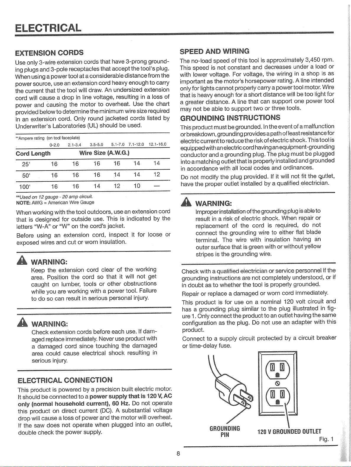
Connect
or
AND
no-load
voltage.
as
lights
heavy
distance.
be
current
with
and
matching
modify
the
proper
is
able
speed
lower
for
is
not
product
a
not
WARNING:
Improper
in
result
replacement
connect
terminal.
surface
outer
stripes
with
a
instructions
to
as
doubt
replace
or
product
grounding
a
Only
1.
time-delay
connect
to
WIRING
this
not
motor’s
the
cannot
enough
to
of
constant
For
properly
for
line
A
support
voltage,
horsepower
a
speed
INSTRUCTIONS
must
grounding
an
is
qualified
a
grounded.
be
reduce
to
electric
grounding
a
that
outlet
all
with
plug
the
outlet
installation
risk
of
a
of
the
grounding
The
wire
that
the
grounding
whether
damaged
a
for
use
is
plug
the
the
as
supply
fuse.
plug.
provides
the
cord
local
provided.
installed
of
electric
the
is
electrician
are
the
on
similar
product
circuit
tool
and
carry
short
that
two
risk
having
plug.
is
properly
codes
the
cord
with
green
not
tool
a
Do
protected
approximately
is
decreases
wiring
the
rating.
power
a
distance
support
can
or
three
the
event
In
path
a
electric
of
an
plug
The
installed
and
Ifitwill
qualified
a
by
grounding
shock.
is
required,
either
to
wire
insulation
with
or
wire.
service
or
completely
properly
is
worn
or
nominal
to
not
the
an
use
plug
outlet
to
rpm.
3,450
load
a
under
is
shop
in
a
line
intended
A
Wire
motor.
tool
light
too
be
will
This
tool
plugged
grounded
utIet,
the
to
or
not
an
if
circuit
in
same
the
with
breaker
tool
power
one
tools.
ofamalfunction
resistance
least
of
shock.
equipment-grounding
be
must
and
ordinances.
fit
not
electrician.
able
plug
is
repair
When
do
blade
flat
having
without
cord
120
an
by
yellow
personnel
understood,
grounded.
immediately.
volt
illustrated
having
adapter
circuit
a
or
as
for
for
the
or
and
fig
this
is
if
ELECTRICAL
be
cause
does
check
is
connected
household
on
the
This
should
It
only
this
drop
the
If
double
product
(normal
product
will
saw
CONNECTION
to
current
power
of
a
by
power
a
current),
supply.
powered
direct
loss
a
not
operate
power
precision
supply
(DC).
the
and
when
built
Hz.
60
A
substantial
motor
plugged
that
Do
electric
is
not
will
into
motor.
V,
120
operate
voltage
overheat.
an
outlet,
AC
GROUNDING
PIN
8
120VGROUNDED
OUTLET
Fig.1

ELECTRICAL
A
WARNING:
To
prevent
qualified
certain
possible
electrician
it
that
is
properly
electrical
check
wired.
the
hazards,
line
if
you
have
are
not
120
VOLT
WIRING
a
GRAY
BLACK
CHANGING
See
Figures
A
WARNING:
Electric
ous
personal
source
This
table
saw
60
Hz.
Only
a
qualified
the
diagrams
MOTOR
2-3.
shock
until
electrician
provided
can
injury,
all
assembly
is
prewired
VOLTAGE
kill.
To
never
steps
should
in
figures
reduce
connect
at
the
rewire
2
-
are
3
TO
the
plug
factory
as
240
risk
of
to
power
completed.
for
this
product
reference.
seri
120
using
V,
240
VOLT
WIRING
BLACK
GRAY
Fig.
2
Fig.
3
9

GLOSSARY
OF
TERMS
Anti-Kickback
the
which,
front
device
A
designed
is
toward
Arbor
on
shaft
The
Cut
Bevel
900
operation
to
the
cutting
A
than
Chamfer
removing
cut
A
angled
is
end)
the
Compound
cut
cross
A
Cross
A
Cut
cutting
of
width
Cutter
rotating
A
blades
Cut
Dado
non-through
A
trough
or
the
Head
cutterhead
knives
or
the
in
Featherboard
orSPM
minute
per
movement.
used
device
A
securely
it
operation.
FPM
Feet
blade
to
Freehand
Performing
fence,
miter
Gum
A
sticky,
sap-based
Heel
Alignment
Kerf
The
slot
of
material
produced
Kickback
end
that
the
End
of
Cut
operation
blade
hazard
A
throwing
Leading
The
Miter
cutting
A
to
the
Pawis
when
stop
to
the
of
which
table
wedge
a
rather
Cut
with
made
shaping
workpiece.
(planers
remove
which
cut
workpiece
to
against
(or
without
cut
a
gauge,
blade
the
removed
the
by
can
workpiece
workpiece
the
other
(radial
properly
workpiece
the
saw
blade
a
made
surface.
from
both
operation
and
with
(requires
control
help
table
the
strokes
other
or
residue
to
by
blade
occur
made
90°.
than
arm
during
cutting
or
with
a
at
than
miter
a
jointer
adjustable
material
produces
per
workpiece
the
aids.
from
fence.
the
the
in
when
back
pushed
with
and
installed
from
ripping
a
blade
the
block
90°.
and
across
made
planers)
from
square-sided
a
special
a
workpiece
the
fence
or
minute),
wood
in
blade
non-through
a
the
toward
into
workpiece
the
table
and
being
tool
is
at
any
the
so
bevel
a
blades
workpiece.
the
during
used
being
products.
through
a
blade
operator.
the
saws)
maintained,
kicked
operation.
mounted.
angle
(or
end
angle.
grain
the
knives.
or
blade).
by
any
in
guided
cut
partial
or
binds
first.
tool
at
back
other
part
or
the
The
notch
guiding
ripping
reference
by
or
cut.
stalls,
or
angle
any
of
or
a
the
Non-Through
cutting
Any
completely
Hole
Pilot
hole
small
A
drilling
Push
Device
cutterhead
operator’s
Push
Devices
during
should
help
large
Blocks
used
Blocks
used
cutting
be
keep
Resaw
cutting
A
to
Resin
sticky,
A
Revolutions
The
minute.
Ripping
cutting
A
Riving
metal
A
keep
Saw
The
applies
cut
operation
thinner
make
sap-based
number
or
operation
Knife/Spreader/Splitter
piece,
kerf
the
Blade
over,
area
to
the
by
Set
distance
The
outward
set)
(planers)
Snipe
Depression
blades
when
Through
cutting
Any
through
the
Throw-Back
throwing
The
workpiece
inadvertently
Workpiece
item
The
Worktable
Surface
cutting,
where
drilling,
Cuts
operation
through
(drill
drilled
holes
(for
to
during
hands
and
to
operations.
used
operator’s
the
Per
turns
of
Rip
open
Path
under,
workpiece,
the
blade.
that
from
made
the
Sawing
operation
thickness
back
being
in
or
which
on
the
presses)
a
in
accurately.
jointer
the
feed
any
well
Push
the
feed
narrow
for
to
pieces.
substance
Minute
completed
Cut
along
slightly
and
the
the
at
workpiece
of
dropped
contact
Material
the
the
planing,
where
thickness
workpiece
planers)
workpiece
operation.
from
away
Sticks
workpiece
A
ripping
hands
(RPM)
the
thinner
also
behind,
that
tip
of
of
face
either
where
of
the
workpiece
a
with
operation
or
the
the
into
sanding
reduce
workpiece
blade
the
the
of
that
over
This
the
table
(for
through
stick
push
operations.
away
well
thickness
has
that
by
a
length
(table
the
than
to
helps
front
in
or
which
area
saw
blade.
the
of
end
properly
not
is
blade
the
workpiece.
the
blade.
the
being
is
rests
does
workpiece.
serves
the
helps
aid
cutterhead.
saws)
(not
from
of
hardened.
spinning
workpiece.
the
of
saws)
blade,
prevent
of
the
will
tooth
blade
workpiece
a
supported.
extends
usually
or
blade
done.
while
operation.
not
guide
as
a
jointer
keep
saw
the
push
a
These
the
workpiece
the
object
which
kickback.
blade.
or
has
be
is
by
completely
caused
being
performing
extend
planer
the
blade
block)
aids
blade.
one
in
helps
As
been
bent
cutter
by
placed
for
it
(or
the
a
10

FEATURES
PRODUCT
Diameter
Blade
Arbor
Blade
Cutting
Cutting
Depth
Depth
SPECIFICATIONS
at
0°
45°
at
ANTI-KICKBACK
KNOB
3-1/8
2-1/4
SPREADER
10
in.
in.
5/8
in.
in.
BLADE
ASSEMBLY
Rating
No
Load
GUARD
Speed
SAW
BLADE
120
240
V,
RIP
V,
AC
AC
FENCE
Only,
Only,
60
60
3,450
6.7
r/min.
13
Amps
Amps
(RPM)
Hz,
Hz,
FRONT
RAIL
LOCKING
HANDLE
BEVEL
ADJUSTING
HAND
WH
EEL
ASSEMBLY
LEVELING
FOOT
STORAGE
HOOK
LEG
STAND
HEIGHT
ADJUSTING
HAND
WHEEL
ASSEMBLY
HERC-U-LIFT®
MOBILE
BASE
MOTOR
COVER
Fig.
4
11

FEATURES
5.
this
of
on
product,
safety
thrown
is
designed
should
of
cabinet.
the
-
the
maximum
the
the
of
such
use
Failure
TABLE
the
PAWLS
The
blade
same
as
blades
injury.
KNOW
See
The
the
wellasa
use
features
YOUR
Figure
use
safe
information
knowledge
this
of
and
ANTI-KICKBACK
workpiece
are
pawls
reduce
BEVEL
to
the
BEVEL
cabinet
BLADE
that
blade
injury
ADJUSTING
the
set
side
SCALE
shows
you
styles
angle
of
-
use
For
operations
complete
with
you
WARMNG:
A
not
Do
tool.
this
personal
in
SAW
product
tool
and
project
of
the
familiarize
rules.
-
Kickback
toward
back
snag
to
kickback
HANDWHEEL
blade
the
easy-to-read
blade
exact
performance,
provided
quality
high
ripping.
information.
rated
heed
to
requires
this
in
you
yourself
the
workpiece
the
occur.
bevel
for
angle.
with
Your
less
warning
this
an
operator’s
are
is
operator.
-
cuts.
scale
your
are
local
than
understanding
attempting.
all
with
hazard
a
The
to
this
Use
is
It
on
the
recommended
it
is
saw.
available
the
can
speed
dealer
could
manual
Before
operating
which
in
toothed
prevent
handwheel
located
of
front
Additional
specific
for
provide
of
result
as
the
on
the
BLADE
height
and
of
HEIGHT
of
blade
HERC-U-LIFT®
mobile
MITER
or
a
angle
MITER
grooves
RAILS
and
RIP
and
SCALE
provides
SPREADER
which
SWITCH
switch
OFF
the
ers
adjusting
must
cabinet,
the
for
cross
for
extension
FENCE
is
position,
key
not
unlocked
be
LOCK
handwheel,
HEIGHT
ADJUSTING
use
adjustments
that
base
GAUGE
The
cut.
miter
a
GAUGE
on
-
Front
GROOVES
either
and
tables.
-
A
secured
-
with
Found
precise
metal
-
A
keep
helps
ASSEMBLY
located
below
remove
location
a
in
qualified
KNOB
before
HANDWHEEL
handwheel
this
replacement.
or
MOBILE
allows
-
This
BASE®
for
miter
easy-to-read
cut.
the
of
side
rails
rear
on
the
the
metal
locking
front
sturdy
measurements
piece,
open
kerf
the
-
This
front
the
switch
the
inaccessible
that
is
use
the
to
the
in
knob,
-
This
handwheel
the
locks
handwheel.
turning
easy
gauge
The
-
blade.
provide
fence
the
-
to
-
This
mobility.
indicator
miter
support
guides
Located
lower
saw
aligns
shows
gauge
lever.
easy-to-read
the
rail,
cuts.
rip
in
slightlythinnerthan
prevent
and
easy
an
has
saw
lock
from
the
the
children
to
tool.
rail.
To
key
center
on
and
comes
the
rides
for
the
the
the
kickback.
access
switch
switch.
the
of
place
into
front
the
the
raise
with
for
wood
exact
the
these
in
fence
rip
workpiece
scale
blade
saw
power
in
Place
oth
and
a
the
BLADE
blade
GUARD
through-sawing
for
-
Always
keep
cuts.
the
guard
down
over
the
12

TOOLS
following
The
NEEDED
tools
includedordrawntoscale)
(not
are
needed
for
assembly
and
alignment:
COMBINATION
LOOSE
SCREWDRIVER
SQUARE
PARTS
PHILLIPS
COMBINATION
(10 mm,
WRENCH
13
mm,18mm)
FLATHEAD
SCREWDRIVER
\
(3)
FRAMING
11
SQUARE
Fig.
5
Front
1
2
Screw(M6x50)
Tube
3
Flanged
4
Caster
5
6
U-Bolt
Tube
Support
Nut
(M12)
12
9
Fig.
6
7
8
9
10
11
12
13
U-Bolt
Hex
Rear
Unlock
Screw
Center
HexNut(M8)
2
4
1
4
4
1
Tube
Nut(M6)
Tube
Pedal
(M6x35)
Brace
Assembly
1
10
2
4
4
1
4
13

LOOSE
t
PARTS
Key
No.
10
11
12
13
14
15
1
2
3
4
5
6
7
8
9
Description
Head
Flat
Carriage
Brace
Side
Washer
Nut
Hex
Leveling
Brace,
Belt
Hex
Screw
Storage
Screw
Wrench
Blade
Blade
Front
Key,
Wrench,
Wrench,
Hex
Bolt
(5/16
Foot
and
1/8
in.,
Bracket
Holder
Screw
-
18)
Rear
2.5,
closed
open
3,
4, 5,6mm
end
end
26
Qty.
Fig.
7
Key
Description
No.
4
8
2
8
8
4
2
1
6
4
2
2
1
1
1
16
17
18
19
20
21
22
23
24
25
26
27
28
29
30
Saw
Blade
Bolt
Hex
Lock
Washer
Washer
Flat
Blade Guard
Rear
Rail,
Rail,
Rear
Rail
Connector
Rail,
Front
Rail,
Front
Rail
Front
Washer
Flat
Washer
Lock
Screw
Washer
Star
Assembly
right
left
right
left
Holder
Oty.
1
8
8
8
1
1
1
1
1
1
1
10
10
10
2
14

LOOSE
PARTS
UST
B
%9
1
15
Key
No.
.2
10
11
12
13
14
15
16
3
4
5
6
7
8
9
Description
Table
Saw
Table
Extension,
Support
HexNut
Washer
Lock
Washer
Flat
Threaded
Fence
Rip
Locking
Screw
Port
Dust
Dust
Chute
Bolt
Hex
Handwheel
Lock
Knob
Miter
Gauge
Rail
Stud
Handle
left
and
right
14
13
12
11
Fig.
oty.
8
1
2
4
6
6
6
6
1
1
4
1
1
4
2
2
1
15
 Loading...