

RIDGID R41121 Operator's Manual
OPERATOR’S MANUAL
MANUEL D’UTILISATION
MANUAL DEL OPERADOR
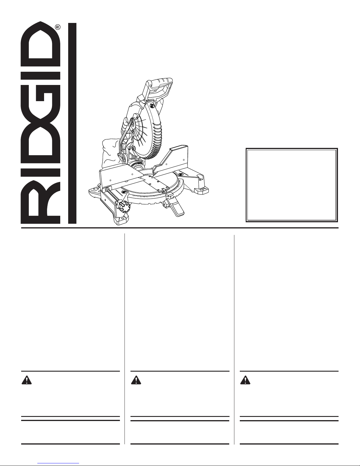
10 in. COMPOUND MITER SAW WITH LED
SCIE À ONGLETS COMPOSÉS
DE 254 mm (10 po) AVEC DEL
SIERRA INGLETEADORA COMBINADA
DE 254 mm (10 pulg.) CON LED
R41121
To register your RIDGID
33.9
22.5
33.9
22.5
product, please visit:
http://register.RIDGID.com
TABLE OF CONTENTS
****************
General Safety Rules .......................2-3
Miter Saw Safety Rules ...................3-4
Additional Safety Rules ...................4-5
Symbols ..............................................6
Electrical ............................................. 7
Glossary of Terms ...............................8
Features .........................................9-11
Tools Needed ...................................12
Loose Parts List ................................12
Assembly .....................................13-19
Operation .....................................20-29
Adjustments ................................30-32
Maintenance ................................33-34
Accessories ...................................... 34
Warranty ...........................................35
Parts Ordering/Service ....... Back Page
50
45
40
35
31.6
30
25
22.5
20
15
10
50
45
40
15
20
22.5
31.6
25
30
35
TABLE DES MATIÈRES
****************
Règles de sécurité générales ..........2-3
Règles de sécurité scie à onlgets ....3-4
Règles de sécurité supplémentaires ... 4-5
Symboles ............................................6
Caractéristiques électriques ............... 7
Glossaire .............................................8
Caractéristiques ............................9-11
Outils nécessaires ............................12
Liste des pièces détachées .............. 12
Assemblage .................................13-19
Utilisation .....................................20-29
Réglages ......................................30-32
Entretien ......................................33-34
Accessories ...................................... 34
Garantie ............................................ 35
Commande de pièces /
réparation ..........................Page arrière
Pour enregistrer votre produit de
RIDGID, s’il vous plaît la visite :
http://register.RIDGID.com
Para registrar su producto de
RIDGID, por favor visita:
http://register.RIDGID.com
ÍNDICE DE CONTENIDO
****************
Reglas de seguridad generales .......2-3
Reglas de seguridad sierra
ingleteadora ....................................3-4
Advertencias de seguridad
adicionales ......................................4-5
Símbolos ............................................6
Aspectos eléctricos ............................ 7
Glosario de términos .......................... 8
Características ..............................9-11
Herramientas necesarias .................. 12
Lista de piezas sueltas ..................... 12
Armado ........................................13-19
Funcionamiento ...........................20-29
Ajustes .........................................30-32
Mantenimiento .............................33-34
Accessorios ...................................... 34
Garantía ............................................ 35
Pedidos de piezas/
servicio .......................... Pág. posterior
WARNING:
To reduce the risk of injury, the user
must read and understand the operator’s manual before using this
product.
SAVE THIS MANUAL FOR
FUTURE REFERENCE
AVERTISSEMENT :
Pour réduire les risques de blessures,
l’utilisateur doit lire et veiller à bien
comprendre le manuel d’utilisation
avant d’utiliser ce produit.
CONSERVER CE MANUEL
POUR FUTURE RÉFÉRENCE
ADVERTENCIA:
Para reducir el riesgo de lesiones, el
usuario debe leer y comprender el
manual del operador antes de usar
este producto.
GUARDE ESTE MANUAL
PARA FUTURAS CONSULTAS

GENERAL SAFETY RULES
WARNING:
Read all safety warnings, instructions, illustrations and specifications provided with this power
tool. Failure to follow all instructions listed below
may result in electric shock, fire and/or serious
injury.
Save all warnings and instructions for future reference.
The term “power tool” in the warnings refers to your mainsoperated (corded) power tool or battery-operated (cordless)
power tool.
WORK AREA SAFETY
Keep work area clean and well lit. Cluttered or dark
areas invite accidents.
Do not operate power tools in explosive atmospheres,
such as in the presence of flammable liquids, gases
or dust. Power tools create sparks which may ignite the
dust or fumes.
Keep children and bystanders away while operating a
power tool. Distractions can cause you to lose control.
ELECTRICAL SAFETY
Power tool plugs must match the outlet. Never modify
the plug in any way. Do not use any adapter plugs with
earthed (grounded) power tools. Unmodified plugs and
matching outlets will reduce risk of electric shock.
Avoid body contact with earthed or grounded surfaces,
such as pipes, radiators, ranges and refrigerators.
There is an increased risk of electric shock if your body
is earthed or grounded.
Do not expose power tools to rain or wet conditions.
Water entering a power tool will increase the risk of electric
shock.
Do not abuse the cord. Never use the cord for carrying,
pulling or unplugging the power tool. Keep cord away
from heat, oil, sharp edges or moving parts. Damaged
or entangled cords increase the risk of electric shock.
When operating a power tool outdoors, use an
extension cord suitable for outdoor use. Use of a cord
suitable for outdoor use reduces the risk of electric shock.
If operating a power tool in a damp location is
unavoidable, use a ground fault circuit interrupter
(GFCI) protected supply. Use of a GFCI reduces the risk
of electric shock.
PERSONAL SAFETY
Stay alert, watch what you are doing and use common
sense when operating a power tool. Do not use a
power tool while you are tired or under the influence
of drugs, alcohol or medication. A moment of inattention
while operating power tools may result in serious personal
injury.
Use personal protective equipment. Always wear eye
protection. Protective equipment such as dust mask,
non-skid safety shoes, hard hat, or hearing protection used
for appropriate conditions will reduce personal injuries.
Prevent unintentional starting. Ensure the switch is in
the off-position before connecting to power source
and/or battery pack, picking up or carrying the tool.
Carrying power tools with your finger on the switch or
energising power tools that have the switch on invites
accidents.
Remove any adjusting key or wrench before turning
the power tool on. A wrench or a key left attached to a
rotating part of the power tool may result in personal injury.
Do not overreach. Keep proper footing and balance
at all times. This enables better control of the power tool
in unexpected situations.
Dress properly. Do not wear loose clothing or jewellery.
Keep your hair, clothing and gloves away from moving
parts. Loose clothes, jewellery or long hair can be caught
in moving parts.
If devices are provided for the connection of dust
extraction and collection facilities, ensure these are
connected and properly used. Use of dust collection
can reduce dust-related hazards.
Do not let familiarity gained from frequent use of tools
allow you to become complacent and ignore tool safety
principles. A careless action can cause severe injury within
a fraction of a second.
POWER TOOL USE AND CARE
Do not force the power tool. Use the correct power
tool for your application. The correct power tool will
do the job better and safer at the rate for which it was
designed.
Do not use the power tool if the switch does not turn
it on and off. Any power tool that cannot be controlled
with the switch is dangerous and must be repaired.
2 - English

GENERAL SAFETY RULES
Disconnect the plug from the power source and/
or remove the battery pack, if detachable, from the
power tool before making any adjustments, changing
accessories, or storing power tools. Such preventive
safety measures reduce the risk of starting the power tool
accidentally.
Store idle power tools out of the reach of children and
do not allow persons unfamiliar with the power tool
or these instructions to operate the power tool. Power
tools are dangerous in the hands of untrained users.
Maintain power tools and accessories. Check for
misalignment or binding of moving parts, breakage
of parts and any other condition that may affect the
power tool’s operation. If damaged, have the power
tool repaired before use. Many accidents are caused
by poorly maintained power tools.
MITER SAW SAFETY RULES
Miter saws are intended to cut wood or wood-like
products, they cannot be used with abrasive cut-off
wheels for cutting ferrous material such as bars, rods,
studs, etc. Abrasive dust causes moving parts such as
the lower guard to jam. Sparks from abrasive cutting will
burn the lower guard, the kerf insert and other plastic
parts.
Use clamps to support the workpiece whenever pos-
sible. If supporting the workpiece by hand, you must
always keep your hand at least 100 mm from either
side of the saw blade. Do not use this saw to cut pieces
that are too small to be securely clamped or held by
hand. If your hand is placed too close to the saw blade,
there is an increased risk of injury from blade contact.
The workpiece must be stationary and clamped or
held against both the fence and the table. Do not feed
the workpiece into the blade or cut ”freehand” in any
way. Unrestrained or moving workpieces could be thrown
at high speeds, causing injury.
Push the saw through the workpiece. Do not pull the
saw through the workpiece. To make a cut, raise the
saw head and pull it out over the workpiece without
cutting, start the motor, press the saw head down
and push the saw through the workpiece. Cutting on
the pull stroke is likely to cause the saw blade to climb
on top of the workpiece and violently throw the blade
assembly towards the operator.
Never cross your hand over the intended line of cut-
ting either in front or behind the saw blade. Supporting
the workpiece ”cross handed” i.e. holding the workpiece
to the right of the saw blade with your left hand or vice
versa is very dangerous.
Keep cutting tools sharp and clean. Properly maintained
cutting tools with sharp cutting edges are less likely to
bind and are easier to control.
Use the power tool, accessories and tool bits etc.
in accordance with these instructions, taking into
account the working conditions and the work to be
performed. Use of the power tool for operations different
from those intended could result in a hazardous situation.
Keep handles and grasping surfaces dry, clean and
free from oil and grease. Slippery handles and grasping
surfaces do not allow for safe handling and control of the
tool in unexpected situations.
SERVICE
Have your power tool serviced by a qualified repair
person using only identical replacement parts. This will
ensure that the safety of the power tool is maintained.
Do not reach behind the fence with either hand closer
than 100 mm from either side of the saw blade, to
remove wood scraps, or for any other reason while
the blade is spinning. The proximity of the spinning saw
blade to your hand may not be obvious and you may be
seriously injured.
Inspect your workpiece before cutting. If the workpiece
is bowed or warped, clamp it with the outside bowed
face toward the fence. Always make certain that there
is no gap between the workpiece, fence and table
along the line of the cut. Bent or warped workpieces can
twist or shift and may cause binding on the spinning saw
blade while cutting. There should be no nails or foreign
objects in the workpiece.
Do not use the saw until the table is clear of all tools,
wood scraps, etc., except for the workpiece. Small
debris or loose pieces of wood or other objects that contact the revolving blade can be thrown with high speed.
Cut only one workpiece at a time. Stacked multiple
workpieces cannot be adequately clamped or braced
and may bind on the blade or shift during cutting.
Ensure the miter saw is mounted or placed on a level,
firm work surface before use. A level and firm work
surface reduces the risk of the miter saw becoming unstable.
Plan your work. Every time you change the bevel or
miter angle setting, make sure the adjustable fence
is set correctly to support the workpiece and will not
interfere with the blade or the guarding system. Without
turning the tool ”ON” and with no workpiece on the table,
move the saw blade through a complete simulated cut to
assure there will be no interference or danger of cutting
the fence.
3 - English

MITER SAW SAFETY RULES
Provide adequate support such as table extensions,
saw horses, etc. for a workpiece that is wider or longer
than the table top. Workpieces longer or wider than the
miter saw table can tip if not securely supported. If the
cut-off piece or workpiece tips, it can lift the lower guard
or be thrown by the spinning blade.
Do not use another person as a substitute for a table
extension or as additional support. Unstable support
for the workpiece can cause the blade to bind or the
workpiece to shift during the cutting operation pulling
you and the helper into the spinning blade.
The cut-off piece must not be jammed or pressed by
any means against the spinning saw blade. If confined,
i.e. using length stops, the cut-off piece could get wedged
against the blade and thrown violently.
Always use a clamp or a fixture designed to properly
support round material such as rods or tubing. Rods
have a tendency to roll while being cut, causing the blade
to bite and pull the work with your hand into the blade.
Let the blade reach full speed before contacting the
workpiece. This will reduce the risk of the workpiece
being thrown.
If the workpiece or blade becomes jammed, turn the
miter saw off. Wait for all moving parts to stop and
disconnect the plug from the power source and/or remove the battery pack. Then work to free the jammed
material. Continued sawing with a jammed workpiece
could cause loss of control or damage to the miter saw.
After finishing the cut, release the switch, hold the
saw head down and wait for the blade to stop before
removing the cut-off piece. Reaching with your hand
near the coasting blade is dangerous.
Hold the handle firmly when making an incomplete cut
or when releasing the switch before the saw head is
completely in the down position. The braking action of
the saw may to be suddenly pulled downward, causing
a risk of injury.
Save these instructions. Refer to them frequently and
use to instruct other users. If you loan someone this tool,
loan them these instructions also.
ADDITIONAL SAFETY RULES
Use the proper extension cord. Make sure your extension
cord is in good condition. Use only a cord heavy enough
to carry the current your product will draw. An undersized
cord will cause a drop in line voltage resulting in loss of
power and overheating. A wire gauge size (A.W.G.) of at
least 14 is recommended for an extension cord 25 feet
or less in length. If in doubt, use the next heavier gauge.
The smaller the gauge number, the heavier the cord.
Inspect tool cords periodically. If damaged, have
repaired by a qualified service technician at an authorized
service facility. Repair or replace a damaged or worn cord
immediately. Stay constantly aware of cord location and
keep it well away from the rotating blade.
Inspect extension cords periodically and replace if
damaged.
Polarized plugs. To reduce the risk of electric shock,
this tool has a polarized plug (one blade is wider than the
other). This plug will fit in a polarized outlet only one way.
If the plug does not fit fully in the outlet, reverse the plug.
If it still does not fit, contact a qualified electrician to install
the proper outlet. Do not change the plug in any way.
Know your power tool. Read the operator’s manual
carefully. Learn the applications and limitations as well
as the specific potential hazards related to this tool.
Always wear eye protection with side shields which
is marked to comply with ansi Z87.1 when using this
product. Failure to do so could result in objects being
thrown into your eyes, resulting in possible serious injury.
Never stand on tool. Serious injury could occur if the tool
is tipped or if the cutting tool is unintentionally contacted.
Keep guards in place and in good working order.
Use the right direction of feed. Feed work into a blade,
cutter, or sanding spindle against the direction of rotation
of the blade, cutter, or sanding spindle only.
Never leave tool running unattended. Turn the power
off. Don’t leave tool until it comes to a complete stop.
Use only correct blades. Do not use blades with incorrect
size holes. Never use blade washers or blade bolts that
are defective or incorrect. The maximum blade capacity
of your saw is 10 in.
Before making a cut, be sure all adjustments are se-
cure.
Never touch blade or other moving parts during use.
Double check all setups. Make sure blade is tight and
not making contact with saw or workpiece before connecting to power supply.
Firmly clamp or bolt your tool to a workbench or table
at approximately hip height.
Make sure the miter table and saw arm (bevel
function) are locked in position before operating
your saw. Lock the miter table by pushing the
miter lock lever down. Lock the saw arm (bevel
function) by securely tightening the bevel lock knob.
4 - English

ADDITIONAL SAFETY RULES
Never move the workpiece or make adjustment to any
cutting angle while the saw is running and the blade
is rotating. Any slip can result in contact with the blade
causing serious personal injury.
Avoid awkward operations and hand positions where a
sudden slip could cause your hand to move into the blade.
ALWAYS make sure you have good balance. NEVER
operate your miter saw on the floor or in a crouched
position.
Never stand or have any part of the body in line with the
path of the saw blade.
Do not turn the motor switch on and off rapidly. This
could cause the saw blade to loosen and could create
a hazard. Should this ever occur, stand clear and allow
the saw blade to come to a complete stop. Disconnect
your saw from the power supply and securely retighten
the blade bolt.
If any part of this miter saw is missing or should
break, bend, or fail in any way, or should any electrical
component fail to perform properly, shut off the power
switch, remove the miter saw plug from the power source
and have damaged, missing, or failed parts replaced
before resuming operation.
Always turn off the saw before disconnecting it to avoid
accidental starting when reconnecting to power supply.
NEVER leave the saw unattended while connected to a
power source.
This tool should have the following markings:
• To reduce the risk of injury, user must read and understand the operator’s manual before using the miter saw.
• Keep hands and body out of the path of the saw blade.
Contact with the blade will result in serious injury.
• Do not operate saw without guards in place.
• Check guarding system to make sure it is functioning
correctly.
• Do not perform any operation freehand.
• Never reach around the saw blade.
• Turn off tool and wait for saw blade to stop before raising saw arm, moving workpiece, or changing settings.
• Disconnect the saw from the power source before
changing blade or servicing.
Always carry the tool only by the carrying handle.
This saw can tip over if the saw head is released suddenly
and the saw is not secured to a work surface. Always
secure this saw to a stable work surface before any use
to avoid serious personal injury.
Always make sure the saw blade has clearance of
all obstructions before turning the saw on.
5 - English
SYMBOLS
The following signal words and meanings are intended to explain the levels of risk associated with this product.
SYMBOL SIGNAL MEANING
DANGER:
WARNING:
CAUTION:
NOTICE:
Some of the following symbols may be used on this tool. Please study them and learn their meaning. Proper
interpretation of these symbols will allow you to operate the tool better and safer.
SYMBOL NAME
Safety Alert Indicates a potential personal injury hazard.
Read Operator’s Manual
Eye Protection
Indicates a hazardous situation, which, if not avoided, will result in death or
serious injury.
Indicates a hazardous situation, which, if not avoided, could result in death or
serious injury.
Indicates a hazardous situation, that, if not avoided, may result in minor or
moderate injury.
(Without Safety Alert Symbol) Indicates information considered important, but
not related to a potential injury (e.g. messages relating to property damage).
DESIGNATION/EXPLANATION
To reduce the risk of injury, user must read and understand operator’s manual before using this product.
Always wear eye protection with side shields marked to comply
with ANSI Z87.1.
No Hands Symbol
Wet Conditions Alert Do not expose to rain or use in damp locations.
V Volts Voltage
A Amperes Current
Hz Hertz Frequency (cycles per second)
min Minutes Time
Alternating Current Type of current
n
o
.../min Per Minute Revolutions, strokes, surface speed, orbits, etc., per minute
No Load Speed Rotational speed, at no load
Class II Construction Double-insulated construction
Failure to keep your hands away from the blade will result in
serious personal injury.
6 - English
ELECTRICAL
DOUBLE INSULATION
Double insulation is a concept in safety in electric power
tools, which eliminates the need for the usual three-wire
grounded power cord. All exposed metal parts are isolated
from the internal metal motor components with protecting
insulation. Double insulated tools do not need to be
grounded.
WARNING:
The double insulated system is intended to protect
the user from shock resulting from a break in the
tool’s internal wiring. Observe all normal safety
precautions to avoid electrical shock.
NOTE: Servicing of a product with double insulation requires
extreme care and knowledge of the system and should
be performed only by a qualified service technician. For
service, we suggest you return the tool to your nearest
authorized service center for repair. Always use original
factory replacement parts when servicing.
ELECTRICAL CONNECTION
This tool has a precision-built electric motor. It should be
connected to a power supply that is 120 V, AC only (normal
household current), 60 Hz. Do not operate this tool on
direct current (DC). A substantial voltage drop will cause a
loss of power and the motor will overheat. If the tool does
not operate when plugged into an outlet, double check the
power supply.
EXTENSION CORDS
When using a power tool at a considerable distance from
a power source, be sure to use an extension cord that has
the capacity to handle the current the product will draw. An
undersized cord will cause a drop in line voltage, resulting in
overheating and loss of power. Use the chart to determine
the minimum wire size required in an extension cord. Only
round jacketed cords listed by Underwriter’s Laboratories
(UL) should be used.
When working outdoors with a product, use an extension
cord that is designed for outside use. This type of cord is
designated with “WA” or “W” on the cord’s jacket.
Before using any extension cord, inspect it for loose or
exposed wires and cut or worn insulation.
**Ampere rating (on product data plate)
0-2.0 2.1-3.4 3.5-5.0 5.1-7.0 7.1-12.0 12.1-16.0
Cord Length Wire Size (A.W.G.)
25' 16 16 16 16 14 14
50' 16 16 16 14 14 12
100' 16 16 14 12 10 —
**Used on 12 gauge - 20 amp circuit.
NOTE: AWG = American Wire Gauge
WARNING:
Keep the extension cord clear of the working area.
Position the cord so that it will not get caught on
lumber, tools, or other obstructions while you are
working with a power tool. Failure to do so can
result in serious personal injury.
WARNING:
Check extension cords before each use. If
damaged replace immediately. Never use tool with
a damaged cord since touching the damaged area
could cause electrical shock resulting in serious
injury.
7 - English

GLOSSARY OF TERMS
Anti-Kickback Pawls (radial arm and table saws)
A device which, when properly installed and maintained,
is designed to stop the workpiece from being kicked back
toward the front of the saw during a ripping operation.
Arbor
The shaft on which a blade or cutting tool is mounted.
Bevel Cut
A cutting operation made with the blade at any angle other
than 90° to the table surface.
Chamfer
A cut removing a wedge from a block so the end (or part of
the end) is angled rather than at 90°.
Compound Cut
A cross cut made with both a miter and a bevel angle.
Cross Cut
A cutting or shaping operation made across the grain or the
width of the workpiece.
Cutter Head (planers and jointer planers)
A rotating cutterhead with adjustable blades or knives. The
blades or knives remove material from the workpiece.
Dado Cut (table saws and compound sliding miter saws)
A non-through cut which produces a square, three-sided
notch or trough in the workpiece.
Featherboard (table saws)
A device used to help control the workpiece by guiding
it securely against the table or fence during any ripping
operation.
FPM or SPM
Feet per minute (or strokes per minute), used in reference
to blade movement.
Freehand
Performing a cut without the workpiece being guided by a
fence, miter fence, or other aids.
Gum
A sticky, sap-based residue from wood products.
Heel
Alignment of the blade to the fence.
Kerf
The material removed by the blade in a through cut or the
slot produced by the blade in a non-through or partial cut.
Kickback
A hazard that can occur when the blade binds or stalls,
throwing the workpiece in the direction of the spinning blade.
Miter Cut
A cutting operation made with the workpiece at any angle
to the blade other than 90°.
Non-Through Cuts (table saws and compound sliding
miter saws)
Any cutting operation where the blade does not extend
completely through the thickness of the workpiece. This is a
cut where the blade will not cut the workpiece into two pieces.
Pilot Hole (drill presses and scroll saws)
A small hole drilled in a workpiece that serves as a guide
for drilling large holes accurately or for insertion of a scroll
saw blade.
Push Blocks (jointer planers)
Device used to feed the workpiece over the jointer planer
cutterhead during any operation. This aid helps keep the
operator’s hands well away from the cutterhead.
Push Blocks and Push Sticks (table saws)
Devices used to feed the workpiece through the saw blade
during cutting operations. When making a narrow rip cut
without a jig or similar cutting aid, always use a push stick
(not a push block). A push block can be used for narrow
ripping operations, if a jig or similar cutting aid is used.
These aids help keep the operator’s hands well away from
the blade.
Rabbet
A non-through cut positioned on the end or edge of the
workpiece which produces a square, two-sided notch or
trough in the workpiece.
Resaw (table saws and band saws)
A cutting operation to reduce the thickness of the workpiece
to make thinner pieces.
Resin
A sticky, sap-based substance that has hardened.
Revolutions Per Minute (RPM)
The number of turns completed by a spinning object in one
minute.
Ripping or Rip Cut (table saws)
A cutting operation along the length of the workpiece and
typically in the direction of the grain.
Riving Knife/Spreader/Splitter (table saws)
A metal piece, slightly thinner than the blade, which helps
keep the kerf open and also helps to prevent kickback.
Saw Blade Path
The area over, under, behind, or in front of the blade. As it
applies to the workpiece, that area which will be or has been
cut by the blade.
Snipe (planers)
Depression made at either end of a workpiece by cutter
blades when the workpiece is not properly supported.
Taper Cut
A cut where the material being cut has a different width at
the beginning of the cut from the end.
Through Sawing
Any cutting operation where the blade extends completely
through the thickness of the workpiece. This type of cut will
separate a single workpiece into two pieces.
Workpiece or Material
The item on which the operation is being done.
Worktable
Surface where the workpiece rests while performing a
cutting, drilling, planing, or sanding operation.
8 - English

FEATURES
PRODUCT SPECIFICATIONS
Blade Diameter ............................................................10 in.
Arbor Hole ................................................................. 5/8 in.
No Load Speed ..................................... 5,000 r/min. (RPM)
Input ................................. 120 V, AC Only, 60 Hz, 15 Amps
Cutting Capacity with Miter at 0°/Bevel 0°:
Maximum nominal lumber sizes .....................2 in. x 6 in.
or 4 in. x 4 in.
Cutting Capacity with Miter at 45°/Bevel 0°:
Maximum nominal lumber sizes .....................2 in. x 4 in.
LED
SWITCH
“D” HANDLE
UPPER BLADE
GUARD
LOCK PIN
Cutting Capacity (Right Bevel) with Miter at 0°/Bevel 45°:
Maximum lumber sizes ......................... 3/4 in. x 4-1/4 in.
Cutting Capacity (Left Bevel) with Miter at 0°/Bevel 45°:
Maximum nominal lumber sizes .....................2 in. x 6 in.
Cutting Capacity with Miter at 45°/Bevel 45°:
Maximum nominal lumber sizes .....................2 in. x 4 in.
Cutting Capacity for Baseboards against the fence:
Maximum height ................................... 3-5/8 in. x 3/4 in.
BLADE
WRENCH
SWITCH
TRIGGER
BEVEL
LOCK KNOB
BEVEL
STOP PIN
STORAGE
AREA
FENCE
SCREW
CARRYING
HANDLE
DUST
BAG
SLIDING MITER
FENCE
WORK
CLAMP
33.9
22.5
50
45
MITER
SCALE
33.9
22.5
40
31.6
30
35
MITER
TABLE
20
22.5
25
CONTROL
ARM
LOWER
BLADE GUARD
SLIDING MITER
FENCE
“NO HANDS ZONE”
BOUNDARY LINE
“NO HANDS ZONE”
LABEL
50
45
40
35
31.6
30
25
22.5
20
15
10
15
DETENT
RELEASE
THROAT
PLATE
SAW
BASE
BUTTON
MITER
LOCK LEVER
Fig. 1
9 - English

FEATURES
KNOW YOUR COMPOUND MITER SAW
See Figure 1.
The safe use of this product requires an understanding of
the information on the tool and in this operator’s manual as
well as a knowledge of the project you are attempting. Before
use of this product, familiarize yourself with all operating
features and safety rules.
10 in. BLADE
A 10 in. blade is included with your compound miter saw. It
will cut materials up to 5-1/2 in. wide, depending upon the
angle at which the cut is being made.
BEVEL LOCK KNOB
The bevel lock knob securely locks your compound miter
saw at desired bevel angles. Loosen the bevel lock knob to
release the saw allowing the blade to be tilted either left or
right for bevel cuts. Tighten the knob to lock the saw in place.
NOTE: To obtain right bevel angles, pull the bevel stop pin
out and tilt the saw to the desired angle. Push the bevel stop
pin in for a positive 0° bevel stop.
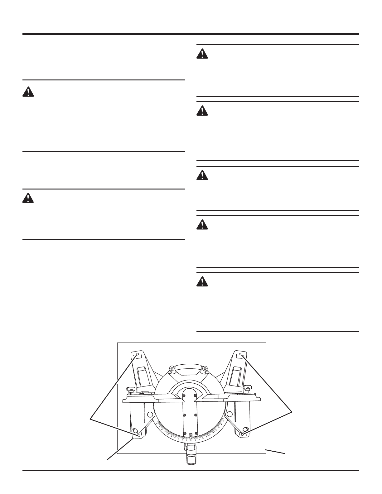
BEVEL STOP ADJUSTMENT SCREWS
See Figure 2.
Bevel stop adjustment screws have been provided on each
side of the saw arm. These adjustment screws are for making fine adjustments at 0°, 33.9°, 45° and 48°.
NOTE: Use the bevel stop turrets to locate 33.9°, 45°, and
48° bevel angles. When making any non-bevel cut, the bevel
stop turrets should be in the 48° position.
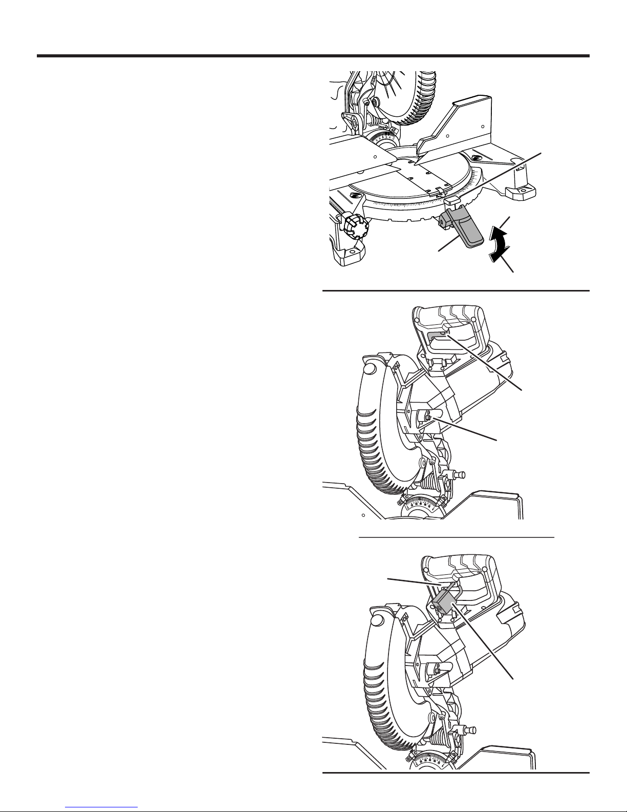
CARRYING HANDLE
See Figure 3.
For convenience when carrying or transporting the miter
saw from one place to another, a carrying handle has been
provided. To transport, turn off and unplug the saw, then
lower the saw arm and lock it in the down position. Lock
saw arm by depressing the lock pin.
BEVEL STOP ADJUSTMENT
SCREW FOR 45° ANGLES
33.9
33.9
22.5
22.5
22.5
33.9º
9
3.
3
4
8
48º
45º
5
4
BEVEL STOP
TURRET
Fig. 2
LOCK
PIN
CARRYING
HANDLE
ELECTRIC BRAKE
An electric brake has been provided to quickly stop blade
rotation after the switch is released.
LED LIGHTING SYSTEM
The LED casts a shadow of the blade teeth onto the
workpiece for making precision cuts and predicts blade kerf
for blade cut line.
MITER LOCK
10 - English
LEVER
LED
SWITCH
SAW ARM LOCKED IN DOWN POSITION
Fig. 3
FEATURES
MITER LOCK LEVER
See Figure 4.
The miter lock lever securely locks the saw at the desired
miter angle. Push the lever down to lock the saw in place.
To release the saw, lift the miter lock lever and depress the
detent release button.
POSITIVE STOPS ON MITER TABLE
Positive stops have been provided at 0°, 15°, 22.5°, 31.6°,
and 45°. The 0°, 15°, 22.5°, 31.6°, and 45° positive stops
have been provided on both the left and right side of the
miter table.
33.9
22.5
33.9
22.5
DETENT
RELEASE
BUTTON
50
45
40
35
31.6
30
25
22.5
20
15
10
50
45
31.6
40
35
15
20
22.5
25
30
UNLOCK
SELF-RETRACTING LOWER BLADE GUARD
The lower blade guard is made of shock-resistant, seethrough plastic that provides protection from each side of
the blade. It retracts over the upper blade guard as the saw
is lowered into the workpiece.
SPINDLE LOCK BUTTON
See Figure 5.
A spindle lock button has been provided for locking the
spindle which keeps the blade from rotating. Unplug the saw.
Depress and hold the lock button while installing, changing,
or removing blade only.
SLIDING MITER FENCES
The sliding miter fences on your compound miter saw have
been provided to help secure the workpiece when making
cuts; the portion of the miter fence located farthest from the
blade is larger to provide additional vertical support.
The sliding feature makes it easy to remove or adjust the
position of the fences and allow for clearance of the saw arm
when making bevel or compound cuts. Loosen the fence
screw before attempting to slide the miter fence. Once the
desired position of the miter fence is determined, tighten the
fence screw to secure the sliding fence.
MITER
LOCK
LEVER
33.9
33.9
22.5
22.5
LOCK
SWITCH
TRIGGER
SPINDLE
LOCK
BUTTON
Fig. 4
SWITCH TRIGGER
See Figure 5.
To prevent unauthorized use of the compound miter saw,
disconnect it from the power supply and lock the switch in
the OFF position. To lock the switch, install a padlock (not
included) through the hole in the switch trigger and make
certain the switch is inoperable. If the switch is still operable
with the padlock installed, a padlock with a larger shackle
diameter must be used. Store the padlock key in another
location.
11 - English
SWITCH
TRIGGER
PADLOCK
33.9
33.9
22.5
22.5
Fig. 5
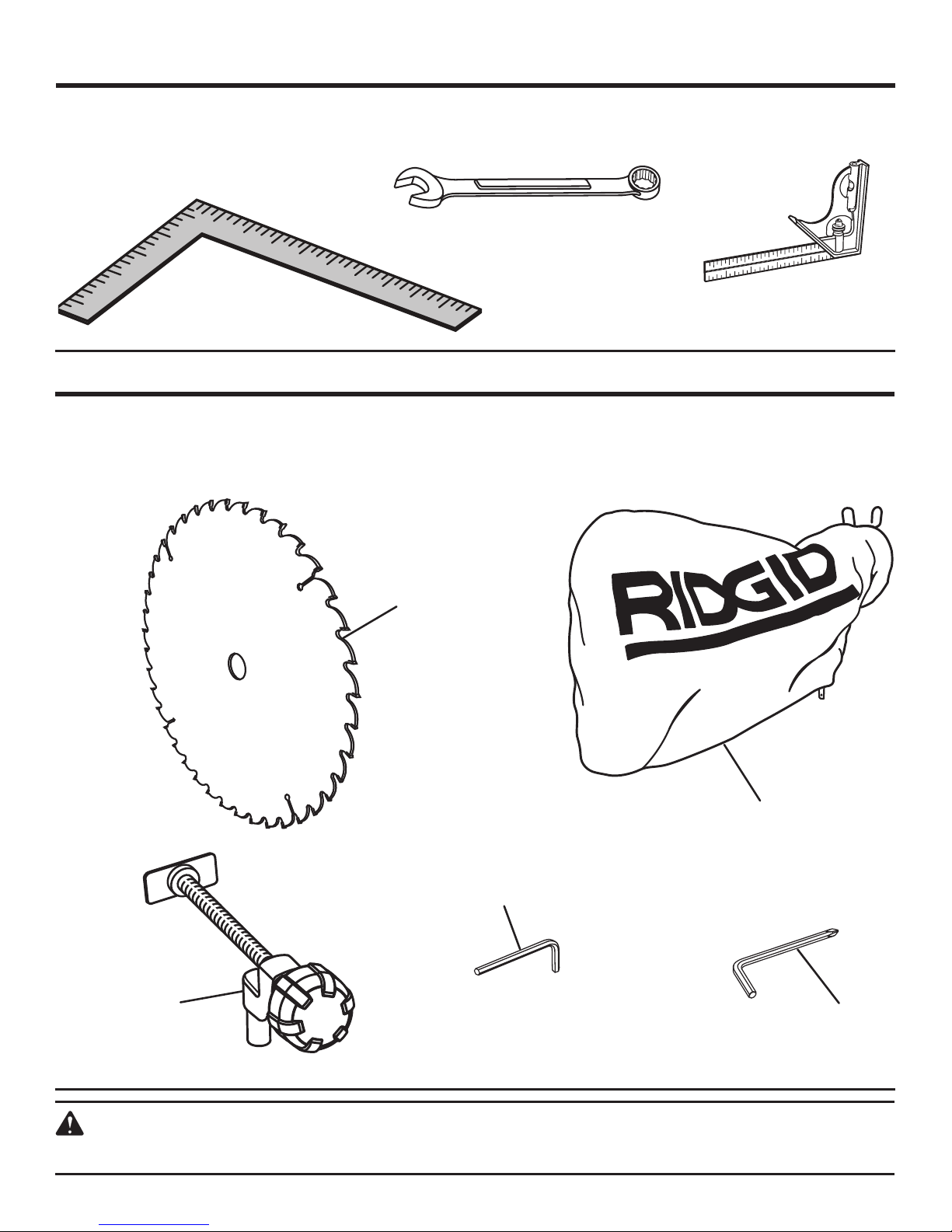
TOOLS NEEDED
The following tools (not included) are needed for making adjustments:
SQUARE
COMBINATION WRENCH
LOOSE PARTS
The following items are included with your Compound Miter Saw:
Blade
Blade Wrench
Dust Bag
Hex Key (3 mm and 5 mm)
COMBINATION SQUARE
Fig. 6
Work Clamp
Operator’s Manual (Not Shown)
WORK
CLAMP
BLADE
3 mm
DUST BAG
HEX
KEY
5 mm
BLADE
WRENCH
WARNING:
The use of attachments or accessories not listed might be hazardous and could cause serious personal injury.
Fig. 7
12 - English
ASSEMBLY
UNPACKING
This product requires assembly.
Carefully lift saw from the carton by the carrying handle
and the saw base, and place it on a level work surface.
WARNING:
Do not use this product if any parts on the Loose
Parts List are already assembled to your product
when you unpack it. Parts on this list are not
assembled to the product by the manufacturer and
require customer installation. Use of a product that
may have been improperly assembled could result
in serious personal injury.
This saw has been shipped with the saw arm secured in
the down position. To release the saw arm, push down
on the top of the saw arm, cut the tie-wrap, and pull out
the lock pin.
WARNING:
The saw arm is spring loaded. Hold the handle
down to prevent it from snapping up when cutting
the tie-wrap. Failure to do so could result in
possible serious injury.
Lift the saw arm by the handle. Hand pressure should
remain on the saw arm to prevent sudden rise upon
release of the tie wrap.
Inspect the tool carefully to make sure no breakage or
damage occurred during shipping.
Do not discard the packing material until you have carefully
inspected and satisfactorily operated the tool.
The saw is factory set for accurate cutting. After assembling
it, check for accuracy. If shipping has influenced the
settings, refer to specific procedures explained in this
manual.
If any parts are damaged or missing, please call
1-866-539-1710 for assistance.
WARNING:
If any parts are damaged or missing do not operate
this product until the parts are replaced. Use of this
product with damaged or missing parts could result
in serious personal injury.
WARNING:
Do not attempt to modify this product or create
accessories not recommended for use with this
tool. Any such alteration or modification is misuse
and could result in a hazardous condition leading
to possible serious personal injury.
WARNING:
Do not connect to power supply until assembly is
complete. Failure to comply could result in accidental
starting and possible serious personal injury.
WARNING:
Do not start the compound miter saw without
checking for interference between the blade and
the miter fence. Damage could result to the blade if
it strikes the miter fence during operation of the saw.
WARNING:
This saw can tip over if the saw head is released
suddenly and the saw is not secured to a work
surface. ALWAYS secure this saw to a stable work
surface before any use to avoid serious personal
injury.
TRACE HOLES
AT THESE LOCATIONS
FOR HOLE PATTERN
SAW BASE
13 - English
TRACE HOLES
AT THESE LOCATIONS
FOR HOLE PATTERN
MOUNTING
SURFACE
Fig. 8
ASSEMBLY
MOUNTING HOLES
See Figure 8.
WARNING:
Before starting any cutting operation, clamp or bolt
your miter saw to a workbench or an approved miter saw stand. If a miter saw stand is used, read operator’s manual and follow the instructions for the
miter saw stand. Never operate your miter saw on
the floor or in a crouched position. Failure to heed
this warning can result in serious personal injury.
The compound miter saw should be mounted to a firm supporting surface such as a workbench, mounting board, or
miter saw stand. The saw base has four mounting holes. If
using bolts, they should be of sufficient length to accommodate the saw base, lock washers, hex nuts, and the thickness of the workbench or other mounting surface. Tighten
all bolts or screws securely.
The hole pattern for mounting to a workbench is shown in
figure 8. Carefully check the workbench after mounting to
make sure that no movement can occur during use. If any
tipping, sliding, or walking is noted, secure the workbench
to the floor before operating.
BLADE
WRENCH
STORAGE
BLADE
WRENCH
Fig. 9
DUST
BAG
EXHAUST
PORT
BLADE WRENCH
See Figure 9.
A blade wrench is packed with this saw. One end of the
wrench is a Phillips screwdriver and the other end is a hex
key. Use the hex key end when installing or removing blade
and the Phillips end when removing or loosening screws.
A storage area for the blade wrench is located on the back
of the saw base.
DUST BAG
See Figure 10.
A dust bag is provided for use on the miter saw. It fits over the
exhaust port on the upper blade guard. To install it, squeeze
the two metal clips to open the mouth of the bag and slide
it on the exhaust port. Release the clips. The metal ring in
the bag should lock in between the grooves on the exhaust
port. To remove the dust bag for emptying, simply reverse
the above procedure.
WORK CLAMP
See Figure 11.
WARNING:
In some operations, the work clamp assembly may
interfere with the operation of the blade guard assembly. Always make sure there is no interference
with the blade guard prior to beginning any cutting
operation to reduce the risk of serious personal injury.
The work clamp provides greater control by clamping the
workpiece to the fence. It also prevents the workpiece from
creeping toward the saw blade. This is very helpful when
cutting compound miters.
Fig. 10
31.6
30
25
22.5
20
15
10
50
45
31.6
40
30
35
15
20
22.5
25
40
50
45
40
35
WORK
CLAMP
BASE
Fig. 11
Depending on the cutting operation and the size of the
workpiece, it may be necessary to use a C-clamp instead of the
work clamp to secure the workpiece prior to making the cut.
To install the work clamp:
Place the shaft of the work clamp in either hole on the
miter table base.
Rotate the knob on the work clamp to move it in or out
as needed.
50
45
14 - English
ASSEMBLY
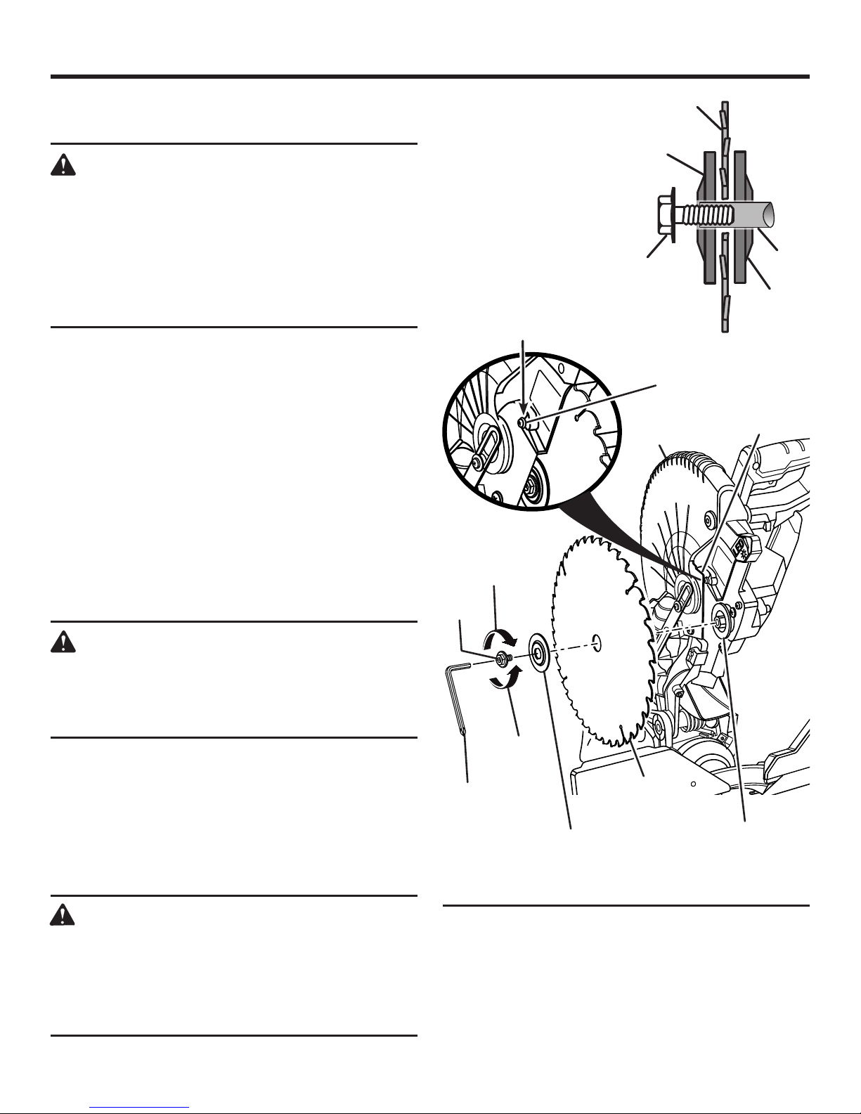
TO INSTALL THE BLADE
See Figure 12.
WARNING:
A 10 in. blade is the maximum blade capacity of
the saw. Never use a blade that is too thick to allow
outer blade washer to engage with the flats on the
spindle. Larger blades will come in contact with the
blade guards, while thicker blades will prevent the
blade bolt from securing the blade on the spindle.
Either of these situations could result in a serious
accident and can cause serious personal injury.
Unplug the saw.
Raise saw arm.
Rotate lower blade guard up and loosen blade bolt cover
screw. Slide blade bolt cover toward upper blade guard
to expose the blade bolt.
Depress the spindle lock button and rotate the blade bolt
until the spindle locks.
Using the wrench provided, loosen and remove the blade
bolt.
NOTE: The blade bolt has left hand threads. Turn blade
bolt clockwise to loosen.
Remove the outer blade washer. Do not remove the inner
blade washer.
Wipe a drop of oil onto the inner blade washer and the
outer blade washer where they contact the blade.
NOTE: BEFORE USE,
REPLACE SCREW AND
TIGHTEN SECURELY
TO PREVENT GUARD
MOVEMENT
TO
LOOSEN
BLADE
BOLT
OUTER
BLADE
WASHER
BLADE
BOLT
LOWER
BLADE
GUARD
BLADE
ARBOR
INNER
BLADE
WASHER
BLADE BOLT
COVER SCREW
BLADE BOLT
COVER
WARNING:
If inner blade washer has been removed, replace
it before placing blade on spindle. Failure to do
so could cause an accident since blade will not
tighten properly.
Fit saw blade inside upper blade guard and onto spindle.
The blade teeth point downward at the front of saw as
shown in figure 12.
Replace the outer blade washer. The double “D” flats on
the blade washers align with the flats on the spindle.
Depress spindle lock button and replace blade bolt.
NOTE: The blade bolt has left hand threads. Turn blade
bolt counterclockwise to tighten.
CAUTION:
Always install the blade with the blade teeth and
the arrow printed on the side of the blade pointing
down at the front of the saw. The direction of blade
rotation is also stamped with an arrow on the upper
blade guard.
TO
TIGHTEN
BLADE
WRENCH
OUTER BLADE
WASHER WITH
DOUBLE “D” FLATS
Tighten blade bolt securely.
Replace blade bolt cover and tighten blade bolt cover-
screw securely.
Lower the blade guard.
Raise and lower the saw arm to ensure lower blade guard
functions correctly.
BLADE
INNER BLADE
WASHER WITH
DOUBLE “D” FLATS
Fig. 12
15 - English

ASSEMBLY
WARNING:
Make sure the spindle lock button is not engaged
before reconnecting saw into power source. Never
engage spindle lock button when blade is rotating.
CUTTING A SLOT IN THE ZERO CLEARANCE
THROAT PLATE
In order to use your compound miter saw, you must cut
a slot through the zero clearance throat plate to allow for
blade clearance. To cut the slot, set your saw at 0° bevel,
turn saw on and allow the blade to reach full speed, then
carefully make a straight cut as far as it will go through the
throat plate. Turn your saw off and allow the blade to come
to a complete stop before raising the saw arm.
Adjust both sliding miter fences to ensure proper clearance
prior to making a bevel cut. Set the bevel angle (right) to 48°,
turn your saw on and allow the blade to reach full speed,
then carefully make another cut through the zero clearance
throat plate. Next, set the bevel angle (left) to 48°, turn your
saw on and allow the blade to reach full speed, then carefully
make another cut through the zero clearance throat plate.
The slot in the throat plate will then be wide enough to allow the blade to pass through it at any angle from 0° to 48°.
Reset the position of the sliding miter fences.
LOCKING/UNLOCKING THE SAW ARM
See Figure 13.
To unlock and raise the saw arm:
Firmly grasp the “D” handle and apply downward pres-
sure while at the same time pulling the lock pin out and
away from the saw housing.
Release the lock pin and slowly raise the saw arm.
To lock the saw arm:
Firmly grasp the “D” handle and apply downward pres-
sure while at the same time pushing the lock pin in and
toward the saw housing.
Release the lock pin allowing it to lock the saw into place.
“D”
HANDLE
LOCK
PIN
Fig. 13
16 - English
ASSEMBLY
NOTE: Many of the illustrations in this manual show only
portions of the compound miter saw. This is intentional so
that we can clearly show points being made in the illustrations. Never operate the saw without all guards securely
in place and in good operating condition.
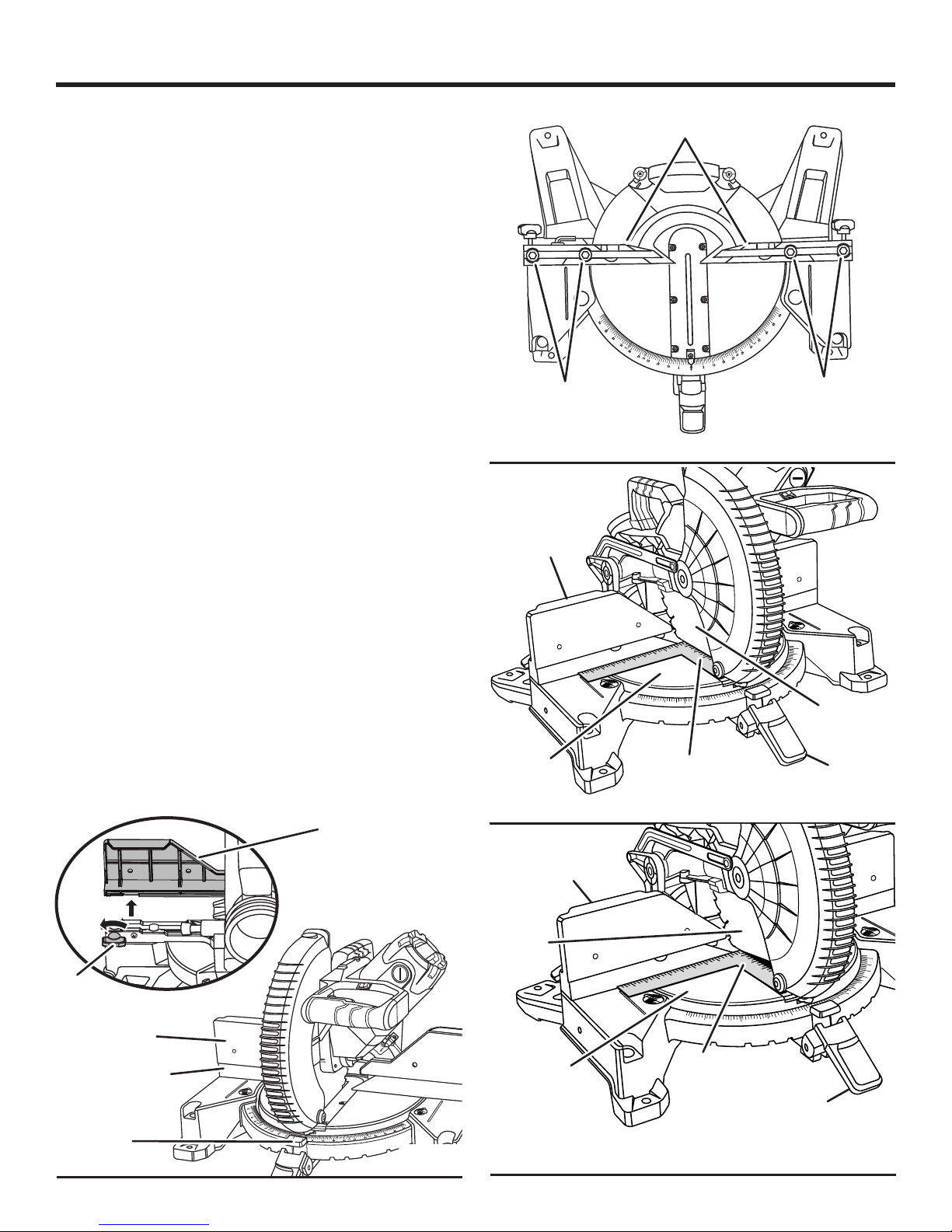
SQUARING THE BLADE TO THE FENCE
See Figures 14 - 20.
Unplug the saw.
Pull the saw arm all the way down and engage the lock
pin to hold the saw arm in transport position.
Lift the miter lock lever, then depress and hold the detent
release button to release the miter table.
Rotate the miter table until the scale indicator is positioned
at 0°.
Release the detent release button, enaging the positive
stop notch, then push the miter lock lever down to secure
the miter table.
Loosen bevel lock knob and set saw arm at 0° bevel
(blade set 90° to miter table). Tighten bevel lock knob.
Lay a square flat on the miter table. Place one leg of the
square against the fence. Slide the other leg of the square
against the flat part of saw blade.
NOTE: Make sure that the square contacts the flat part
of the saw blade, not the blade teeth.
The edge of the square and the saw blade should be
parallel as shown in figure 16.
If the front or back edge of the saw blade angles away
from the square as shown in figures 17 and 18, adjustments are needed.
Turn the fence screws counterclockwise 2-3 times to
loosen and slide miter fences toward the saw arm until
they are flush with the miter table.
SOCKET
SCREW
SLIDING
MITER
FENCE
MITER
TABLE
HEAD
50
45
FENCE
31.6
40
30
35
SQUARE
SOCKET
HEAD
SCREW
Fig. 15
50
45
40
35
31.6
30
25
22.5
20
15
10
15
20
22.5
25
BLADE
MITER
LOCK LEVER
FENCE
SCREW
SLIDING MITER
FENCE
FENCE
DETENT
RELEASE
BUTTON
SLIDING MITER
FENCE
Fig. 14
BLADE
17 - English
VIEW OF BLADE SQUARE WITH FENCE
SLIDING
MITER
FENCE
MITER
50
45
40
SQUARE
22.5
31.6
25
30
35
TABLE
MITER LOCK
LEVER
VIEW OF BLADE NOT SQUARE WITH FENCE,
ADJUSTMENTS ARE REQUIRED
Fig. 16
50
45
40
35
31.6
30
25
22.5
20
15
10
15
20
Fig. 17
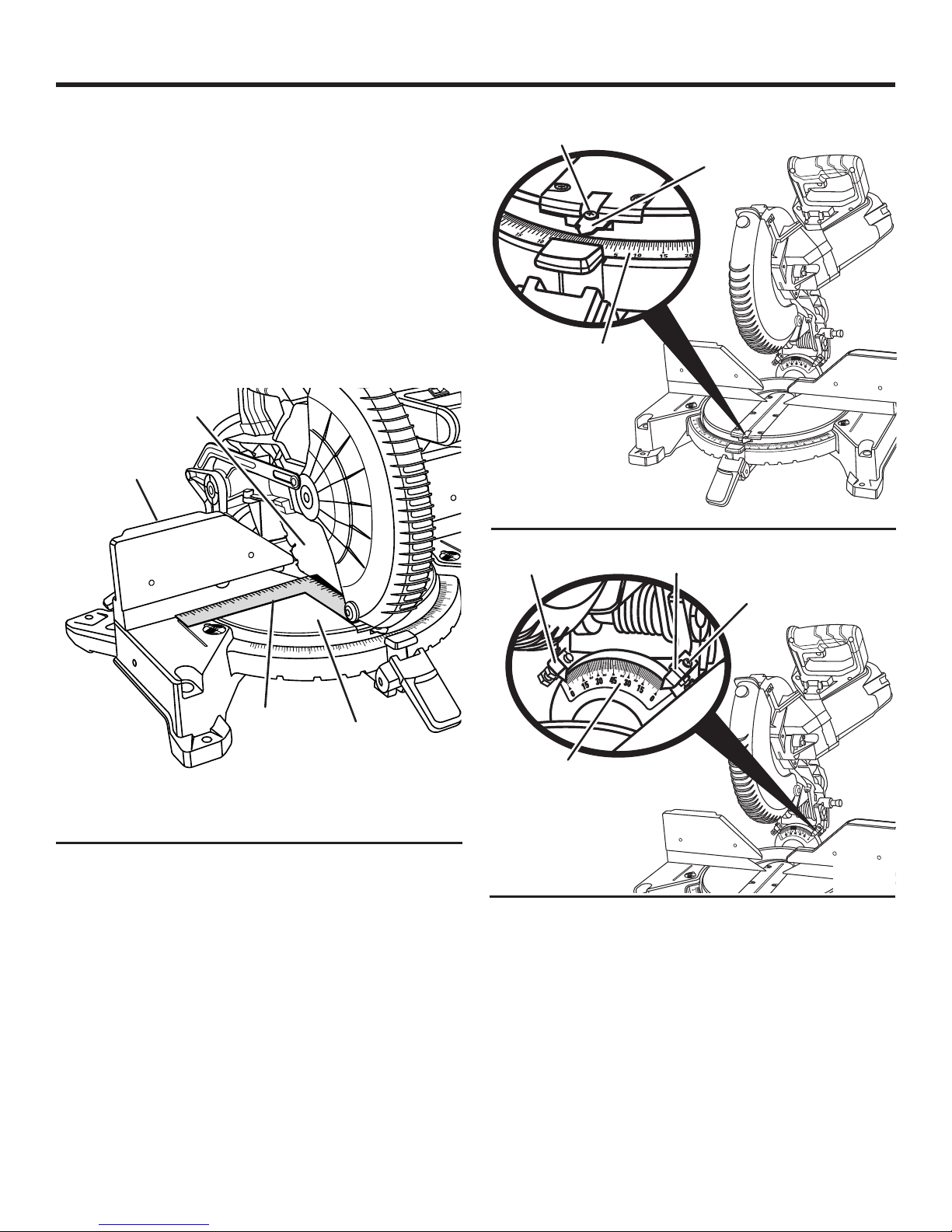
ASSEMBLY
Remove the sliding miter fences by pulling them up and
away from the miter table.
Using the supplied hex wrench, loosen the socket
head screws that secure the fence to the miter table.
See figure 15.
Rotate the fence left or right until the saw blade is parallel
with the square.
Retighten the screws securely. Check blade squareness
to fence and readjust if necessary.
Replace the sliding miter fences.
Your saw has several scale indicators. After squaring adjust-
ments have been made, it may be necessary to loosen the
indicator screws and reset them to zero. See Figures 19 - 20.
BLADE
SLIDING
MITER
FENCE
45
40
35
31.6
30
25
22.5
20
15
10
50
45
31.6
40
30
35
15
20
22.5
25
50
INDICATOR
SCREW
SCALE
INDICATOR
MITER
SCALE
33.9
22.5
33.9
22.5
SCALE
INDICATOR
SCALE
INDICATOR
33.9
33.9
22.5
INDICATOR
SCREW
22.5
Fig. 19
SQUARE
MITER
TABLE
VIEW OF BLADE NOT SQUARE WITH FENCE,
ADJUSTMENTS ARE REQUIRED
Fig. 18
BEVEL
SCALE
33.9
33.9
22.5
22.5
Fig. 20
18 - English
ASSEMBLY
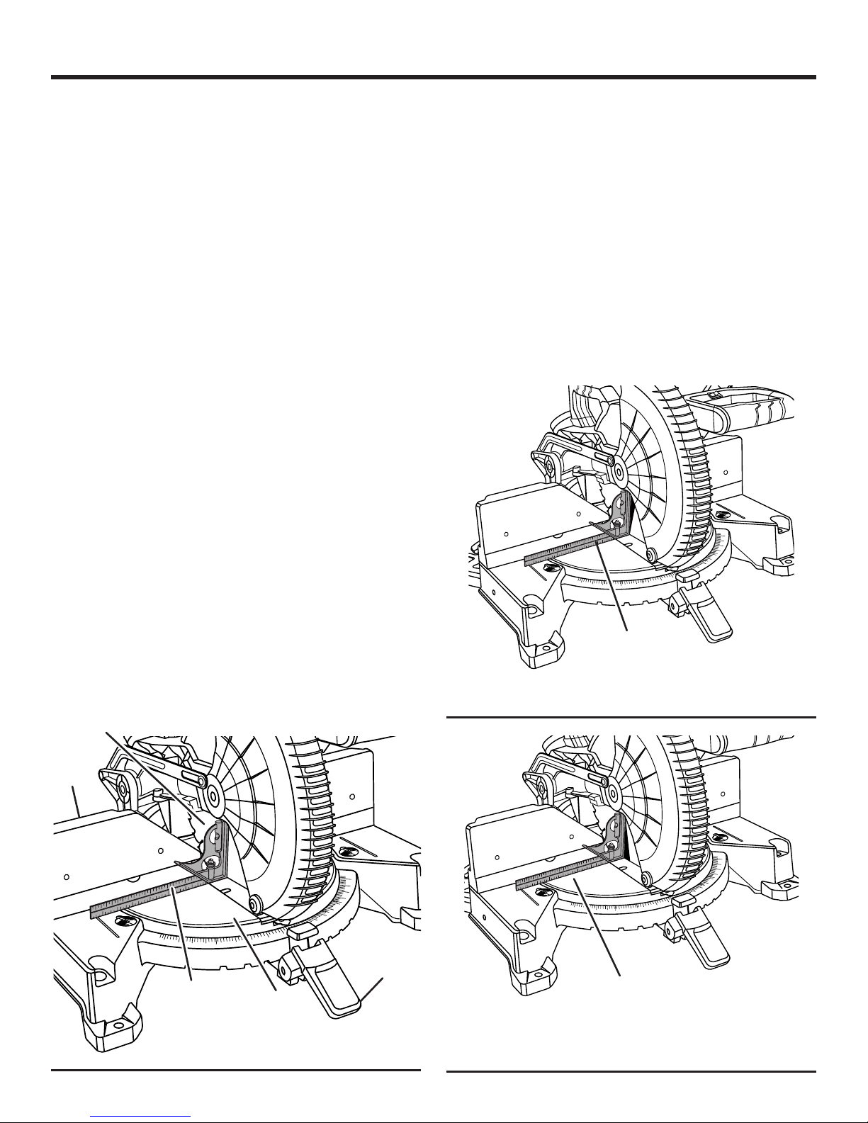
SQUARING THE BLADE TO THE MITER TABLE
See Figures 21 - 23.
To square the blade at 0°:
Unplug the saw.
Pull the saw arm all the way down and engage the lock
pin to hold the saw arm in transport position.
Lift the miter lock lever, then depress and hold the detent
release button to release the miter table.
Rotate the miter table until the scale indicator is positioned
at 0°.
Release the detent release button, enaging the positive
stop notch, then push the miter lock lever down to secure
the miter table.
Push the bevel stop pin inward.
Loosen bevel lock knob and tilt saw arm until it is seated
in the positive 0° bevel stop (blade set 90° to miter table).
Tighten bevel lock knob.
Place a combination square against the miter table and
the flat part of saw blade.
NOTE: Make sure that the square contacts the flat part
of the saw blade, not the blade teeth.
Rotate the blade by hand and check the blade-to-table
alignment at several points.
The edge of the square and the saw blade should be
parallel as shown in figure 21.
If the top or bottom of the saw blade angles away from
the square as shown in figures 22 and 23, adjustments
are needed.
Loosen the bevel lock knob.
Adjust 0° bevel stop screw to bring saw blade into align-
ment with the square. See 0° bevel Adjustment in the
Adjustments section.
BLADE
SLIDING
MITER
FENCE
Retighten bevel lock knob. Recheck blade-to-table align-
ment.
To square the blade at 45°:
Loosen the bevel lock knob and set the saw arm at 45°
bevel. Tighten bevel lock knob.
NOTE: To obtain right bevel angles, pull the bevel stop
pin out and tilt the saw to the desired angle.
Using a combination square, check the blade-to-table
alignment as described earlier.
If adjustments are needed, refer to 45° Bevel Adjustment
in the Adjustments section.
Your saw has several scale indicators. After squaring adjustments have been made, it may be necessary to loosen
the indicators screws and reset them to zero. See Figures
19 and 20.
50
45
40
35
31.6
30
25
22.5
20
15
10
50
45
31.6
40
35
15
20
22.5
25
30
COMBINATION
SQUARE
VIEW OF BLADE NOT SQUARE WITH MITER TABLE,
ADJUSTMENTS ARE REQUIRED
Fig. 22
50
45
31.6
40
30
35
COMBINATION
SQUARE
25
22.5
15
20
MITER
TABLE
10
CORRECT VIEW OF BLADE
SQUARE WITH MITER TABLE
50
45
40
35
31.6
30
25
22.5
20
15
MITER LOCK
LEVER
Fig. 21
19 - English
50
45
40
35
31.6
30
25
22.5
20
15
10
50
45
31.6
40
35
15
20
22.5
25
30
COMBINATION
SQUARE
VIEW OF BLADE NOT SQUARE WITH MITER TABLE,
ADJUSTMENTS ARE REQUIRED
Fig. 23
OPERATION
WARNING:
Do not allow familiarity with tools to make you
careless. Remember that a careless fraction of a
second is sufficient to inflict severe injury.
WARNING:
Always wear eye protection with side shields
marked to comply with ANSI Z87.1. Failure to do
so could result in objects being thrown into your
eyes, resulting in possible serious injury.
WARNING:
Do not use any attachments or accessories not
recommended by the manufacturer of this tool.
The use of attachments or accessories not recommended can result in serious personal injury.
APPLICATIONS
This product has been designed only for the purposes listed
below:
Cross cutting wood and plastic (do not cut metals,
ceramics, or masonry products)
Cross cutting miters, joints, etc. for picture frames, mold-
ings, door casings, and fine joinery
Bevel cutting and compound cutting
NOTE: The blade provided is fine for most wood cutting
operations, but for fine joinery cuts or cutting plastic, use
one of the accessory blades available from the place of
purchase of your new RIDGID miter saw.
WARNING:
Before starting any cutting operation, clamp or bolt
your miter saw to a workbench or leg stand. Never
operate your miter saw on the floor or in a crouched
position. Failure to heed this warning can result in
serious personal injury.
WARNING:
To avoid serious personal injury, keep your hands
outside the no hands zone; at least 3 in. from blade.
Never perform any cutting operation freehand
(without holding workpiece against the fence). The
blade could grab the workpiece if it slips or twists.
WARNING:
Do not start your compound miter saw without
checking for interference between the blade and
the miter fence. Damage could result to the blade
if it strikes the miter fence during operation of the
saw. Failure to heed this warning can also result in
serious personal injury.
CUTTING WITH YOUR COMPOUND MITER
SAW
WARNING:
When using a work clamp or C-clamp to secure
your workpiece, clamp workpiece on one side of
the blade only. The workpiece must remain free
on one side of the blade to prevent the blade from
binding in workpiece. The workpiece binding the
blade will cause motor stalling and kickback. This
situation could cause an accident resulting in possible serious personal injury.
WARNING:
NEVER move the workpiece or make adjustment to
any cutting angle while the saw is running and the
blade is rotating. Any slip can result in contact with
the blade causing serious personal injury.
WARNING:
To avoid serious personal injury, always push the
miter lock lever down and tighten the bevel lock
knob securely before making a cut. Failure to do
so could result in movement of the control arm or
miter table while making a cut.
20 - English
10
15
20
25
22.5
31.6
30
35
40
45
50
15
20
25
30
35
40
45
31.6
22.5
50
33.9
33.9
22.5
22.5
OPERATION
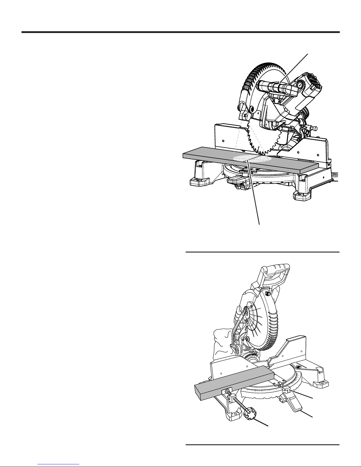
LED LIGHTING SYSTEM
See Figure 24.
The LED lighting system casts the shadow of the blade onto
the workpiece. This results in greater accuracy of cuts and
requires no adjustments.
To use this feature, turn the LED switch on.
Bring the saw arm down so the blade is approximately
1/4 in. from the workpiece. The shadow of the blade will be
projected onto the workpiece, indicating where the blade
teeth will make contact as the cut is made.
TO MITER CUT/CROSS CUT
See Figures 25 - 26.
A cross cut is made by cutting across the grain of the
workpiece. A straight cross cut is made with the miter table
set at the 0° position. Miter cross cuts are made with the
miter table set at some angle other than zero.
Pull out the lock pin and lift saw arm to its full height.
Lift the miter lock lever, then depress and hold the detent
release button to release the miter table.
Rotate the control arm until the pointer aligns with the
desired angle on the miter scale.
Release the detent release button, then push the miter
lock lever down to secure the miter table.
NOTE: You can quickly locate 0°, 15°, 22-1/2°, 31.6°, and
45° left or right by releasing the detent release button as
you rotate the control arm. The control arm will seat itself
in one of the positive stop notches, located in the miter
table base.
Place the workpiece flat on the miter table with one edge
securely against the fence. If the board is warped, place
the convex side against the fence. If the concave edge
of a board is placed against the fence, the board could
collapse on the blade at the end of the cut, jamming the
blade. See Figures 41 - 42.
When cutting long pieces of lumber or molding, support
the opposite end of the stock with a roller stand or with
a work surface level with the saw table. See Figure 30.
Turn the LED switch on.
Lower the blade and align the cutting line on the workpiece
with the edge of saw blade or the blade shadow.
Grasp the stock firmly with one hand and secure it against
the fence. Use the work clamp or a C-clamp to secure
the workpiece when possible.
Before turning on the saw, perform a dry run of the cut-
ting operation to make sure that no problems will occur
when the cut is made.
Grasp the saw handle firmly. Squeeze the switch trigger.
Allow several seconds for the blade to reach maximum
speed.
SHADOW OF BLADE
TEETH PROJECTED ONTO
WORKPIECE
CROSS CUT
WORK
CLAMP
LED
SWITCH
Fig. 24
DETENT
RELEASE
BUTTON
MITER
LOCK LEVER
Fig. 25
21 - English
OPERATION
Slowly lower the blade into and through the workpiece.
Release the switch trigger and allow the saw blade to
stop rotating before raising the blade out of workpiece
and removing the workpiece from the miter table.
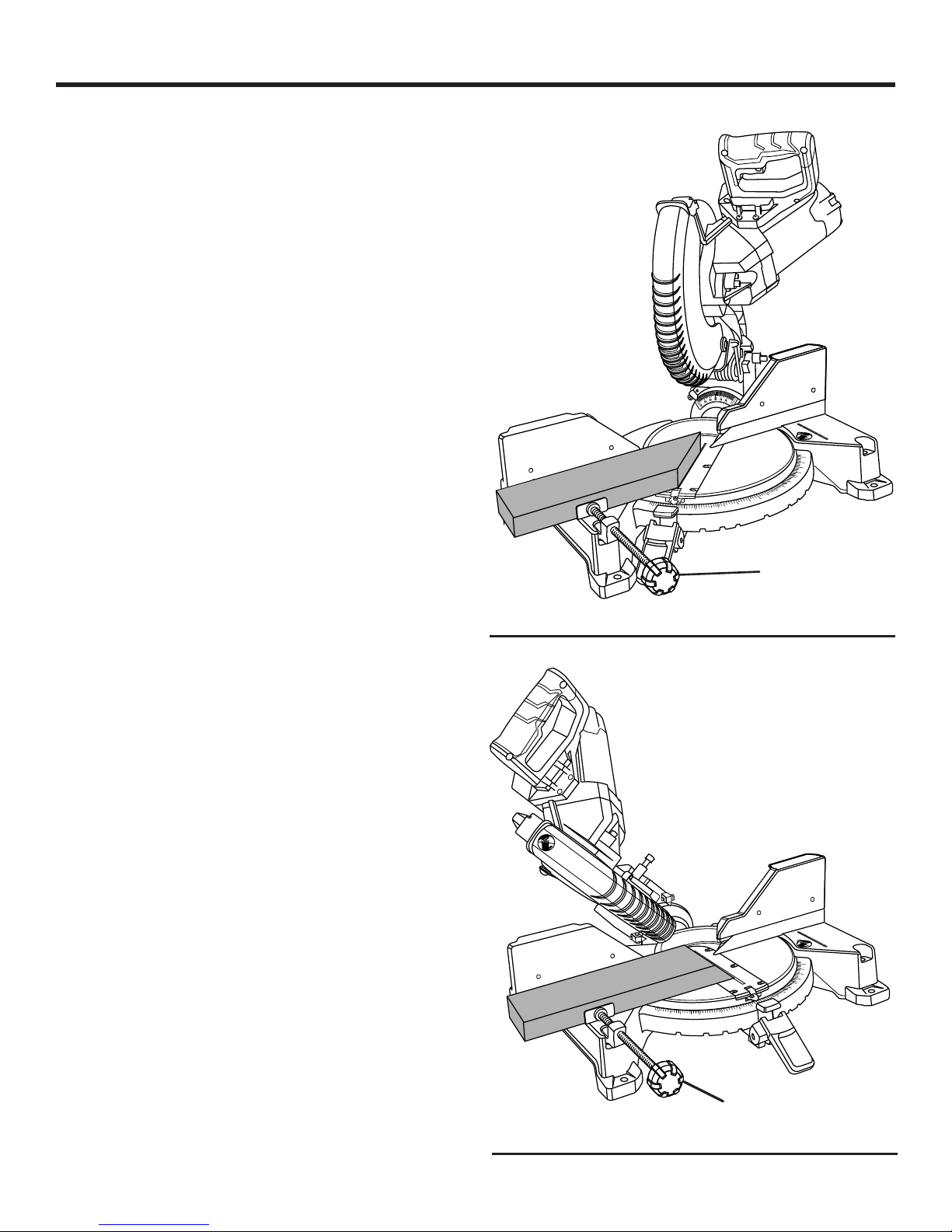
TO BEVEL CUT
See Figures 27 - 28.
A bevel cut is made by cutting across the grain of the
workpiece with the blade angled to the workpiece. A straight
bevel cut is made with the miter table set at the zero degree
position and the blade set at an angle between 0° and 48°.
NOTE: It may be necessary to adjust or remove the sliding
miter fence to ensure proper clearance prior to making the cut.
Pull out the lock pin and lift saw arm to its full height.
Lift the miter lock lever, then depress and hold the detent
release button to release the miter table.
Rotate the control arm until the pointer aligns with 0° on
the miter scale.
Release the detent release button, enaging the positive
stop notch, then push the miter lock lever down to secure
the miter table.
Loosen the bevel lock knob and move the saw arm to
the desired left bevel angle.
NOTE: To obtain right bevel angles, pull the bevel stop
pin out and tilt the saw to the desired right bevel angle.
Left and right bevel angles can be set from 0° to 48°.
NOTE: Use the bevel stop turret to locate 33.9°, 45°, and
48° bevel angles. See Figure 28.
Once the saw arm has been set at the desired angle,
securely tighten the bevel lock knob and push the bevel
stop pin in.
Place the workpiece flat on the miter table with one edge
securely against the fence. If the board is warped, place
the convex side against the fence. If the concave edge
of a board is placed against the fence, the board could
collapse on the blade at the end of the cut, jamming the
blade. See Figures 41 - 42.
When cutting long pieces of lumber or molding, support
the opposite end of the stock with a roller stand or with
a work surface level with the saw table. See Figure 30.
Turn the LED switch on.
Lower the blade and align the cutting line on the workpiece
with the edge of saw blade or the blade shadow.
Grasp the stock firmly with one hand and secure it against
the fence. Use the work clamp or a C-clamp to secure
the workpiece when possible.
Before turning on the saw, perform a dry run of the cut-
ting operation to make sure that no problems will occur
when the cut is made.
Grasp the saw handle firmly. Squeeze the switch trigger.
Allow several seconds for the blade to reach maximum
speed.
MITER CUT
50
31.6
35
30
BEVEL CUT
50
45
31.6
40
35
33.9
33.9
22.5
22.5
10
15
20
22.5
25
15
20
22.5
25
30
WORK CLAMP
50
45
40
35
31.6
30
25
22.5
20
15
10
0
WORK CLAMP
50
45
40
35
31.6
30
25
22.5
20
15
10
Fig. 26
Fig. 27
22 - English
OPERATION
Slowly lower the blade into and through the workpiece.
Release the switch trigger and allow the saw blade to
stop rotating before raising the blade out of workpiece
and removing the workpiece from the miter table.
TO COMPOUND MITER CUT
See Figure 29.
A compound miter cut is a cut made using a miter angle and
a bevel angle at the same time. This type of cut is used to
make picture frames, cut molding, make boxes with sloping
sides, and for certain roof framing cuts.
To make this type of cut the control arm on the miter table
must be rotated to the correct angle and the saw arm must
be tilted to the correct bevel angle. Care should always
be taken when making compound miter setups due to the
interaction of the two angle settings.
Adjustments of miter and bevel settings are interdependent
with one another. Each time you adjust the miter setting you
change the effect of the bevel setting. Also, each time you
adjust the bevel setting you change the effect of the miter
setting.
It may take several settings to obtain the desired cut. The
first angle setting should be checked after setting the second
angle, since adjusting the second angle affects the first.
Once the two correct settings for a particular cut have been
obtained, always make a test cut in scrap material before
making a finish cut in good material.
NOTE: It may be necessary to adjust or remove the sliding
miter fence to ensure proper clearance prior to making the cut.
Pull out the lock pin and lift saw arm to its full height.
Lift the miter lock lever and depress the detent release
button to release the miter table.
Rotate the control arm until the pointer aligns with the
desired angle on the miter scale.
Release the detent release button, then push the miter
lock lever down to secure the miter table.
Loosen the bevel lock knob and move the saw arm to
the desired left bevel angle.
NOTE: To obtain right bevel angles, pull the bevel stop
pin out and tilt the saw to the desired right bevel angle.
Left and right bevel angles can be set from 0° to 48°.
NOTE: Use the bevel stop turret to locate 33.9°, 45°, and
48° bevel angles. See Figure 28.
Once the saw arm has been set at the desired angle,
securely tighten the bevel lock knob.
Recheck miter angle setting. Make a test cut in scrap
material.
Place the workpiece flat on the miter table with one edge
securely against the fence. If the board is warped, place
the convex side against the fence. If the concave edge
of a board is placed against the fence, the board could
collapse on the blade at the end of the cut, jamming the
blade. See Figures 41 - 42.
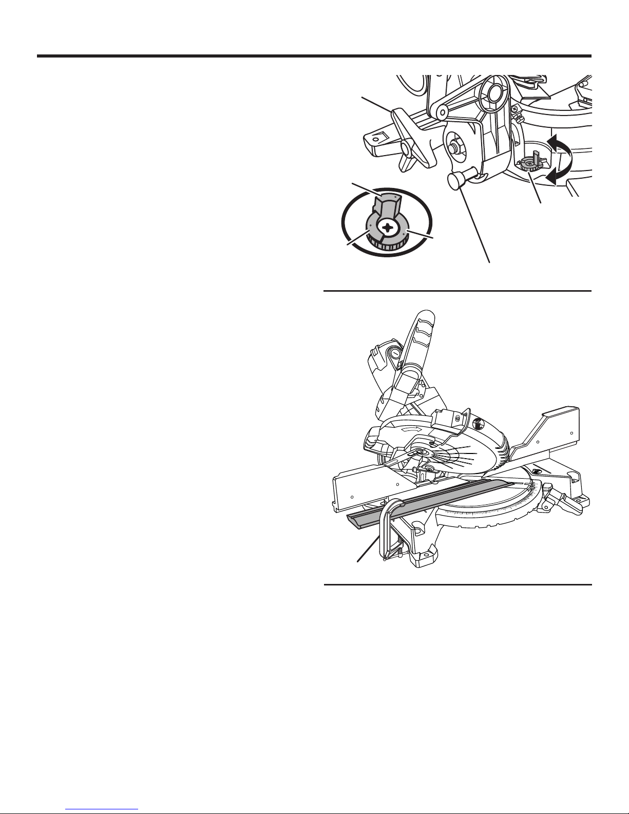
BEVEL
LOCK KNOB
33.9º
9
3.
3
BEVEL STOP TURRET
4
5
8
4
ADJUSTMENT AT 45º
48º
45º
BEVEL STOP TURRET
BEVEL STOP
PIN
Fig. 28
COMPOUND MITER CUT
50
45
40
35
31.6
30
25
22.5
20
15
10
0
10
15
20
22.5
31.6
25
30
35
Fig. 29
C-CLAMP
50
45
40
When cutting long pieces of lumber or molding, support
the opposite end of the stock with a roller stand or with
a work surface level with the saw table. See Figure 30.
Turn the LED switch on.
Lower the blade and align the cutting line on the workpiece
with the edge of saw blade or the blade shadow.
Grasp the stock firmly with one hand and secure it against
the fence. Use the work clamp or a C-clamp to secure
the workpiece when possible.
Before turning on the saw, perform a dry run of the cut-
ting operation to make sure that no problems will occur
when the cut is made.
23 - English
OPERATION
10
15
20
25
22.5
31.6
30
35
50
15
20
25
30
35
40
45
31.6
22.5
50
10
0
33.9
33.9
22.5
22.5
Grasp the saw handle firmly. Squeeze the switch trigger.
Allow several seconds for the blade to reach maximum
speed.
Slowly lower the blade into and through the workpiece.
Release the switch trigger and allow the saw blade to
stop rotating before raising the blade out of workpiece
and removing the workpiece from the miter table.
TO SUPPORT LONG WORKPIECES
See Figure 30.
Long workpieces need extra supports. Supports should be
placed along the workpiece so it does not sag. The support
should let the workpiece lay flat on the base of the saw and
miter table during the cutting operation. Use the work clamp
or C-clamp to secure the workpiece.
TO CLAMP WIDE WORKPIECES
See Figure 31.
When cutting wide workpieces, such as nominal 2 in. x 6 in.,
boards should be clamped with the work clamp or C-clamp.
MAKING AN AUXILIARY FENCE
See Figure 32.
Depending on the size and position of the workpiece, certain
unusual cuts may benefit from the additional support that can
be provided by an auxiliary fence. The holes provided in the
miter fence are used to secure an auxiliary fence in place. To
make an auxiliary fence, we recommend using two pieces of
wood sized 1/2 in. thick, 3-1/2 in. high, and 9-1/2 in. long.
NOTE: The auxiliary fence can only be used when the bevel
is set at 0˚. When making a bevel cut, the auxiliary fence
MUST be removed.
To attach the auxiliary fence to the saw:
Place one 9-1/2 in. piece of wood against the miter fence
and aligned with the left edge of the miter table.
Clamp the wood tightly against the fence and drive wood
screws from the back of the fence through the two holes
and into the auxiliary fence. If necessary, drill a pilot hole
into wood first to prevent splitting. Remove clamp when
finished.
NOTE: Make sure the screws you use to attach the
auxiliary fence do not pass through the front face of the
fence and the length of the screws will not put them in
the path of the blade at any angle.
Make a full left miter cut through the auxiliary fence.
NOTE: Check for interference between the auxiliary fence
and the lower blade guard. Correct any interference before
proceeding.
Repeat steps with second board by aligning with right
side of miter table and making a full right miter cut through
the auxiliary fence.
LONG
WORKPIECE
AUXILIARY
FENCE
WORKPIECE
SUPPORTS
33.9
22.5
33.9
22.5
50
20
22.5
45
31.6
25
40
30
35
33.9
22.5
33.9
22.5
50
45
40
35
31.6
30
25
22.5
20
15
10
50
45
15
20
22.5
31.6
25
40
30
35
Fig. 30
WIDE
BOARD
50
45
40
35
31.6
30
25
22.5
20
15
10
15
Fig. 31
24 - English
ALIGN BOARD WITH
EDGE OF MITER TABLE
Fig. 32

OPERATION
CUTTING COMPOUND MITERS
To aid in making the correct settings, the compound angle setting chart below has been provided. Since compound cuts are
the most difficult to accurately obtain, trial cuts should be made in scrap material, and much thought and planning made,
prior to making your required cut.
PITCH
OF SIDE
0°
5°
10°
15°
20°
25°
30°
35°
40°
45°
50°
55°
60°
65°
70°
75°
80°
85°
90°
4
M- 45.00°
B- 0.00°
M- 44.89°
B- 3.53°
M- 44.56°
B- 7.05°
M- 44.01°
B- 10.55°
M- 43.22°
B- 14.00°
M- 42.19°
B- 17.39°
M- 40.89°
B- 20.70°
M- 39.32°
B- 23.93°
M- 37.45°
B- 27.03°
M- 35.26°
B- 30.00°
M- 32.73°
B- 32.80°
M- 29.84°
B- 35.40°
M- 26.57°
B- 37.76°
M- 22.91°
B- 39.86°
M- 18.88°
B- 41.64°
M- 14.51°
B- 43.08°
M- 9.85°
B- 44.14°
M- 4.98°
B- 44.78°
M- 0.00°
B- 45.00°
5
M- 36.00°
B- 0.00°
M- 35.90°
B- 2.94°
M- 35.58°
B- 5.86°
M- 35.06°
B- 8.75°
M- 34.32°
B- 11.60°
M- 33.36°
B- 14.38°
M- 32.18°
B- 17.09°
M- 30.76°
B- 19.70°
M- 29.10°
B- 22.20°
M- 27.19°
B- 24.56°
M- 25.03°
B- 26.76°
M- 22.62°
B- 28.78°
M- 19.96°
B- 30.60°
M- 17.07°
B- 32.19°
M- 13.95°
B- 33.53°
M- 10.65°
B- 34.59°
M- 7.19°
B- 35.37°
M- 3.62°
B- 35.84°
M- 0.00°
B- 36.00°
NUMBER OF SIDES
6
M- 30.00°
B- 0.00°
M- 29.91°
B- 2.50°
M- 29.62°
B- 4.98°
M- 29.15°
B- 7.44°
M- 28.48°
B- 9.85°
M- 27.62°
B- 12.20°
M- 26.57°
B- 14.48°
M- 25.31°
B- 16.67°
M- 23.86°
B- 18.75°
M- 22.21°
B- 20.70°
M- 20.36°
B- 22.52°
M- 18.32°
B- 24.18°
M- 16.10°
B- 25.66°
M- 13.71°
B- 26.95°
M- 11.17°
B- 28.02°
M- 8.50°
B- 28.88°
M- 5.73°
B- 29.50°
M- 2.88°
B- 29.87°
M- 0.00°
B- 30.00°
M- 25.71°
B- 0.00°
M- 25.63°
B- 2.17°
M- 25.37°
B- 4.32°
M- 24.95°
B- 6.45°
M- 24.35°
B- 8.53°
M- 23.56°
B- 10.57°
M- 22.64°
B- 12.53°
M- 21.53°
B- 14.41°
M- 20.25°
B- 16.19°
M- 18.80°
B- 17.87°
M- 17.20°
B- 19.41°
M- 15.44°
B- 20.82°
M- 13.54°
B- 22.07°
M- 11.50°
B- 23.16°
M- 9.35°
B- 24.06°
M- 7.10°
B- 24.78°
M- 4.78°
B- 25.30°
M- 2.40°
B- 25.61°
M- 0.00°
B- 25.71°
7
8 9
M- 22.50°
B- 0.00°
M- 22.42°
B- 1.91°
M- 22.19°
B- 3.81°
M- 21.81°
B- 5.68°
M- 21.27°
B- 7.52°
M- 20.58°
B- 9.31°
M- 19.73°
B- 11.03°
M- 18.74°
B- 12.68°
M- 17.60°
B- 14.24°
M- 16.32°
B- 15.70°
M- 14.91°
B- 17.05°
M- 13.36°
B- 18.27°
M- 11.70°
B- 19.35°
M- 9.93°
B- 20.29°
M- 8.06°
B- 21.08°
M- 6.12°
B- 21.69°
M- 4.11°
B- 22.14°
M- 2.07°
B- 22.41°
M- 0.00°
B- 22.50°
M- 20.00°
B- 0.00°
M- 19.93°
B- 1.71°
M- 19.72°
B- 3.40°
M- 19.37°
B- 5.08°
M- 18.88°
B- 6.72°
M- 18.26°
B- 8.31°
M- 17.50°
B- 9.85°
M- 16.60°
B- 11.31°
M- 15.58°
B- 12.70°
M- 14.43°
B- 14.00°
M- 13.17°
B- 15.19°
M- 11.79°
B- 16.27°
M- 10.31°
B- 17.23°
M- 8.74°
B- 18.06°
M- 7.10°
B- 18.75°
M- 5.38°
B- 19.29°
M- 3.62°
B- 19.68°
M- 1.82°
B- 19.92°
M- 0.00°
B- 20.00°
10
M- 18.00°
B- 0.00°
M- 17.94°
B- 1.54°
M- 17.74°
B- 3.08°
M- 17.42°
B- 4.59°
M- 16.98°
B- 6.07°
M- 16.41°
B- 7.50°
M- 15.72°
B- 8.89°
M- 14.90°
B- 10.21°
M- 13.98°
B- 11.46°
M- 12.94°
B- 12.62°
M- 11.80°
B- 13.69°
M- 10.56°
B- 14.66°
M- 9.23°
B- 15.52°
M- 7.82°
B -16.26°
M- 6.34°
B- 16.88°
M- 4.81°
B- 17.37°
M- 3.23°
B- 17.72°
M- 1.62°
B- 17.93°
M- 0.00°
B- 18.00°
Each B (Bevel) and M (Miter) Setting is Given to the Closest 0.005°.
COMPOUND-ANGLE SETTINGS FOR POPULAR STRUCTURES
25 - English
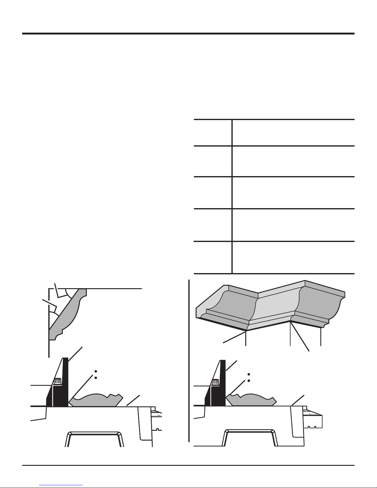
OPERATION
CUTTING CROWN MOLDING
Your compound miter saw does an excellent job of cutting
crown molding. In general, compound miter saws do a better job of cutting crown molding than any other tool made.
In order to fit properly, crown molding must be compound
mitered with extreme accuracy.
The two contact surfaces on a piece of crown molding that
fit flat against the ceiling and the wall of a room are at angles
that, when added together, equal exactly 90°. Most crown
molding has a top rear angle (the section that fits flat against
the ceiling) of 52° and a bottom rear angle (the section that
fits flat against the wall) of 38°.
LAYING MOLDING FLAT ON THE MITER
TABLE
See Figure 33.
To use this method for accurately cutting crown molding for
a 90° inside or outside corner, lay the molding with its broad
back surface flat on the miter table and against the fence.
When setting the bevel and miter angles for compound miters, remember that the settings are interdependent; changing one angle changes the other angle as well.
Keep in mind that the angles for crown moldings are very
precise and difficult to set. Since it is very easy for these
angles to shift, all settings should first be tested on scrap
molding. Also most walls do not have angles of exactly 90°,
therefore, you will need to fine tune your settings.
When cutting crown molding by this method the bevel angle
should be set at 33.9°. The bevel stop turret can be used to
set the bevel angle to 33.9°. The miter angle should be set
at 31.6° either right or left, depending on the desired cut for
the application. See the chart below for correct angle settings
and correct positioning of crown molding on miter table.
The settings in the chart below can be used for cutting All
Standard (U.S.) crown molding with 52° and 38° angles. The
crown molding is placed flat on the miter table using the
compound features of your miter saw.
Bevel
Angle Type of Cut
Setting
Left side, inside corner
33.9°
33.9°
33.9°
33.9°
1. Top edge of molding against fence
2. Miter table set right 31.6°
3. Save left end of cut
Right side, inside corner
1. Bottom edge of molding against fence
2. Miter table set left 31.6°
3. Save left end of cut
Left side, outside corner
1. Bottom edge of molding against fence
2. Miter table set left 31.6°
3. Save right end of cut
Right side, outside corner
1. Top edge of molding against fence
2. Miter table set right 31.6°
3. Save right end of cut
38°
W
52°
A
L
L
CEILING
SLIDING
MITER FENCE
TOP EDGE AGAINST FENCE =
LEFT SIDE, INSIDE CORNER
RIGHT SIDE, OUTSIDE CORNER
INSIDE
CORNER
MITER TABLE
CROWN MOLDING FLAT ON MITER TABLE
SLIDING
MITER FENCE
BOTTOM EDGE AGAINST FENCE =
RIGHT SIDE, INSIDE CORNER
LEFT SIDE, OUTSIDE CORNER
OUTSIDE CORNER
MITER TABLE
Fig. 33
26 - English
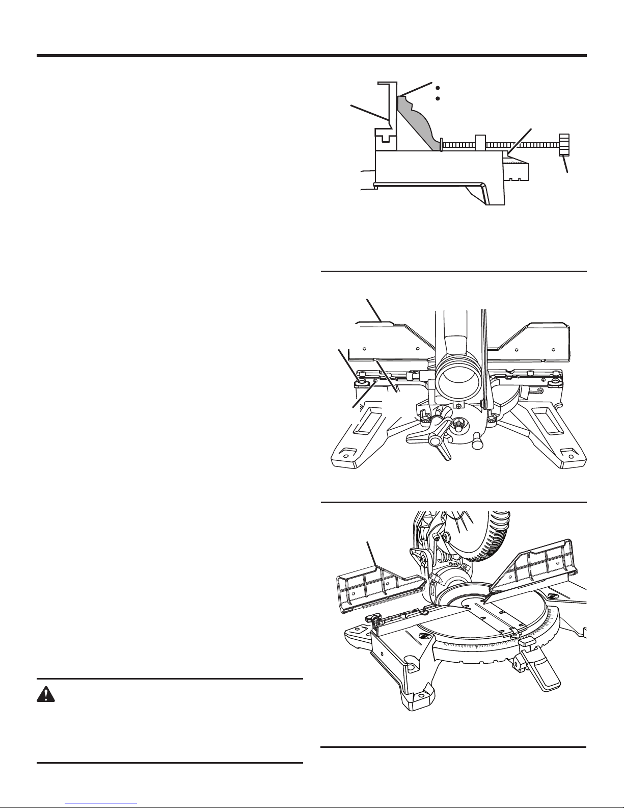
OPERATION
NESTING CROWN MOLDING AGAINST THE
MITER FENCE
See Figures 34 - 40.
To nest pieces of crown molding less than 4-5/8 in. tall:
Set the bevel angle at 0° and the miter angle at 45° to
either the left or the right.
Lay the crown molding on the saw with its bottom edge
resting at a natural angle flush against the fence and its
top edge resting flush against the miter table, this is called
“nesting”.
Position the crown molding in place by using the work
clamp as a material stop.
Tighten the knob on the work clamp until it rests lightly
against the edge of the molding. Do not overtighten as
this may move the material causing misalignment.
Before turning on the saw, perform a dry run of the cut-
ting operation to make sure that no problems will occur
when the cut is made.
Grasp the saw handle firmly. Squeeze the switch trigger.
Allow several seconds for the blade to reach maximum
speed.
Slowly lower the blade into and through the crown mold-
ing.
Release the switch trigger and allow the saw blade to stop
rotating before raising the blade out of the crown molding
and removing the crown molding from the miter table.
To nest pieces of crown molding that are 4-5/8 in. and
taller:
NOTE: This method of cut is for crown molding between
4-5/8 in. and 5-1/4 in. tall. Do not attempt to cut molding
that is larger than 5-1/4 in. tall.
Loosen the fence screw and slide miter fences toward
the saw arm until they are flush with the miter table.
Remove the sliding miter fences by pulling them up and
away from the miter table.
Place the left sliding miter fence on the right side of the
tool and the right sliding miter fence on the left side with
both fences facing the rear of the tool.
Install the miter fences by aligning the small slot in the
fences with the fixed screws on the saw and pushing
down.
NOTE: The fixed screws prevent the sliding miter fences
from sliding too close to the saw arm and possibly interfering with the movement of the blade. Do not remove
fixed screws.
SLIDING
MITER FENCE
SLIDING MITER
FENCE
FENCE
SCREW
FIXED
SCREW
SLIDING MITER
FENCE
BOTTOM EDGE AGAINST FENCE =
RIGHT SIDE, INSIDE CORNER
LEFT SIDE, OUTSIDE CORNER
CROWN MOLDING NESTED AGAINST
FRONT FACING MITER FENCE
SMALL
SLOT
VIEW OF SAW FROM BEHIND WITH
FENCES FACING BACKWARD
10
50
45
31.6
40
35
15
20
22.5
25
30
MITER
TABLE
WORK
CLAMP
Fig. 34
Fig. 35
35
31.6
30
25
22.5
20
15
50
45
40
WARNING:
Only reverse the sliding miter fences in order to
cut nested crown molding between 4-5/8 in. and
5-1/4 in. tall. Making any other cuts with the fences
reversed could result in serious personal injury.
27 - English
VIEW OF SAW FROM FRONT WITH FENCES
FACING BACKWARD
Fig. 36
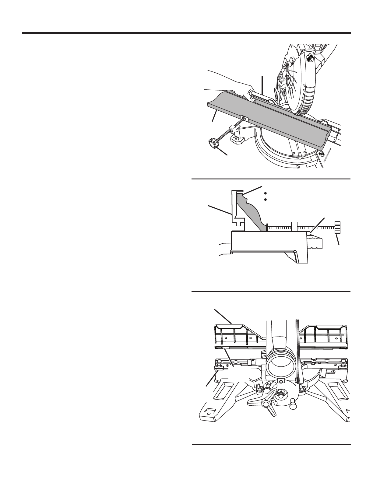
OPERATION
Tighten the fence screws to secure the fences in place.
Set the bevel angle at 0° and the miter angle at 45° to
either the left or the right.
Nest and secure the crown molding against the back of
a sliding miter fence, as shown in figures 37 and 38.
Position the crown molding in place by using the work
clamp as a material stop.
Tighten the knob on the work clamp until it rests lightly
against the edge of the molding. Do not overtighten as
this may move the material causing misalignment.
Hold the workpiece as shown in figure 37 with your hand
on the outside of the sliding miter fence.
Before turning on the saw, perform a dry run of the cut-
ting operation to make sure that no problems will occur
when the cut is made.
Grasp the saw handle firmly. Squeeze the switch trigger.
Allow several seconds for the blade to reach maximum
speed.
Slowly lower the blade into and through the crown mold-
ing.
Release the switch trigger and allow the saw blade to
stop rotating before raising the blade out of the crown
molding and removing the crown molding from the miter
table.
To install the sliding miter fences in their normal operating position:
Loosen the fence screw and slide the miter fences toward
the saw arm until they stop.
NOTE: The fixed screws prevent the sliding miter fences
from sliding too close to the saw arm and possibly interfering with the movement of the blade. Do not remove
fixed screws.
Remove the sliding miter fences by pulling them up and
away from the miter table.
Place the left sliding miter fence on the left side of the
tool and the right sliding miter fence on the right side with
both fences facing the front of the tool.
Install the miter fences by aligning the large slot in the
fences with the fence screw on the saw and pushing
down.
Tighten the fence screws to secure the fences in place.
MOLDING
SLIDING
MITER FENCE
LARGE CROWN MOLDING NESTED AGAINST
SLIDING
MITER FENCE
SLIDING MITER
FENCE
WORK
CLAMP
Fig. 37
BOTTOM EDGE AGAINST FENCE =
RIGHT SIDE, INSIDE CORNER
LEFT SIDE, OUTSIDE CORNER
MITER
TABLE
WORK
CLAMP
REAR FACING MITER FENCE
Fig. 38
LARGE
SLOT
FENCE
SCREW
28 - English
VIEW OF SAW FROM BEHIND WITH
FENCES FACING FORWARD
Fig. 39
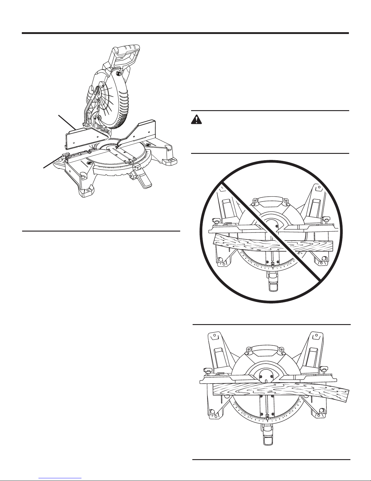
OPERATION
SLIDING
MITER FENCE
FENCE
SCREW
CUTTING WARPED MATERIAL
See Figures 41 - 42.
When cutting warped material, always make sure it is positioned on the miter table with the convex side against the
fence as shown in figure 42.
If the warped material is positioned the wrong way as shown
in figure 41, it will pinch the blade near the completion of
the cut.
WARNING:
To avoid a kickback and to avoid serious personal
injury, never position the concave edge of bowed
50
45
40
35
31.6
30
25
22.5
20
15
10
50
45
40
15
20
22.5
31.6
25
30
35
or warped material against the fence.
VIEW OF SAW FROM FRONT WITH FENCES
FACING FORWARD
Fig. 40
WRONG
Fig. 41
29 - English
RIGHT
Fig. 42
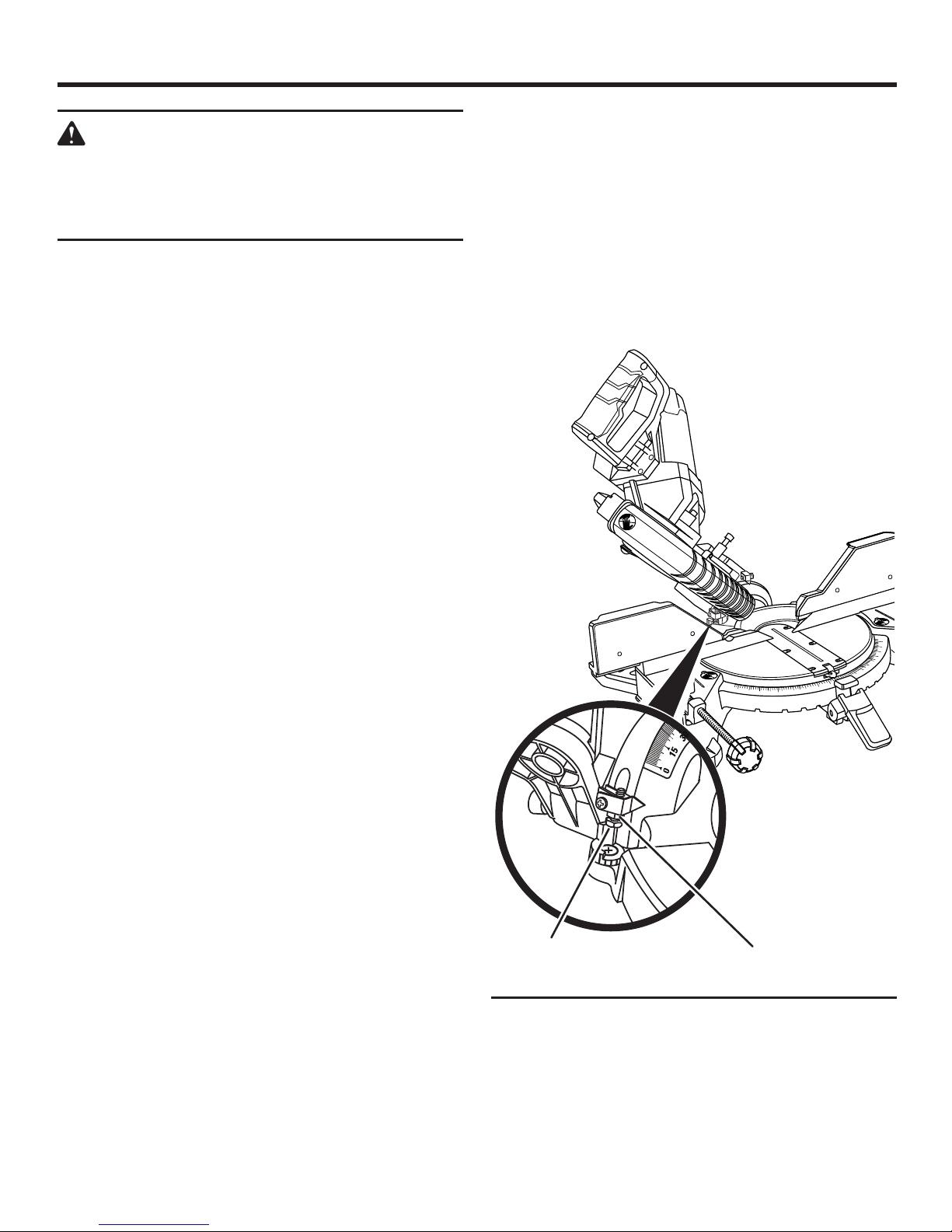
ADJUSTMENTS
WARNING:
Before performing any adjustment, make sure the
tool is unplugged from the power supply. Failure to
heed this warning could result in serious personal
injury.
The compound miter saw has been adjusted at the factory for making very accurate cuts. However, some of the
components might have been jarred out of alignment during shipping. Also, over a period of time, readjustment will
probably become necessary due to wear. After unpacking
the saw, check the following adjustments before you begin
using saw. Make any readjustments that are necessary and
periodically check the parts alignment to make sure that the
saw is cutting accurately.
PIVOT ADJUSTMENTS
NOTE: These adjustments were made at the factory and
normally do not require readjustment.
TRAVEL PIVOT ADJUSTMENT
The saw arm should rise completely to the up position
by itself.
If the saw arm does not raise by itself or if there is play
in the pivot joints, have saw repaired at your nearest
AUTHORIZED SERVICE CENTER.
TO ADJUST THE BEVEL PIVOT
The compound miter saw should bevel easily by loosen-
ing the bevel lock knob and tilting the saw.
NOTE: To obtain right bevel angles, pull the bevel stop
pin out and tilt the saw to the desired angle.
If movement is tight or if there is play in the pivot, have
saw repaired at your nearest AUTHORIZED SERVICE
CENTER.
If the blade is out of square, adjust by tightening or loos-
ening the bevel stop adjustment screw.
Retighten bevel lock knob and push bevel stop pin in.
Recheck blade-to-table alignment.
NOTE: The above procedure can be used to check blade
squareness of the saw blade to the miter table at both
left and right 45° angles.
Your saw has several scale indicators. After squaring adjustments have been made, it may be necessary to loosen
the indicators screws and reset them to zero. See Figures
19 and 20.
50
45
40
35
31.6
30
25
22.5
20
15
10
50
45
40
35
22.5
15
20
22.5
31.6
25
30
45° BEVEL ADJUSTMENT
See Figure 43.
Unplug the saw.
Using a wrench, loosen the lock nut securing bevel stop
adjustment screw.
Loosen the bevel lock knob and set the saw arm at 45°
bevel.
NOTE: To obtain right bevel angles, pull the bevel stop
pin out and tilt the saw to the desired angle.
Square the blade to the miter table as described in the
Assembly section of this manual.
BEVEL STOP
ADJUSTMENT
30 - English
LOCK NUT
Fig. 43
 Loading...