

RIDGID R4021 Operator's Manual
OPERATOR’S MANUAL
MANUEL D’UTILISATION
MANUAL DEL OPERADOR
7 in. TILE SAW
SCIE À CARREAUX DE 178 mm (7 po)
SIERRA DE LOSAS DE 178 mm (7 pulg.)
R4021
To register your RIDGID
product, please visit:
http://register.RIDGID.com
Pour enregistrer votre
produit de RIDGID, s’il vous
plaît la visite :
http://register.RIDGID.com
Para registrar su producto
de RIDGID, por favor visita:
http://register.RIDGID.com
Your saw has been engineered and manufactured to our high standard for dependability, ease of operation, and operator
safety. When properly cared for, it will give you years of rugged, trouble-free performance.
WARNING:
To reduce the risk of injury, the user must read and understand the operator’s manual before using this product.
SAVE THIS MANUAL FOR FUTURE REFERENCE
Cette scie a été conçue et fabriquée conformément aux
strictes normes de fiabilité, simplicité d’emploi et sécurité
d’utilisation. Correctement entretenu, cet outil vous donnera
des années de fonctionnement robuste et sans problème.
Su sierra ha sido diseñado y fabricado de conformidad con
nuestras estrictas normas para brindar fiabilidad, facilidad de
uso y seguridad para el operador. Con el debido cuidado, le
brindará muchos años de sólido funcionamiento y sin problemas.
AVERTISSEMENT :
Pour réduire les risques de blessures, l’utilisateur
doit lire et veiller à bien comprendre le manuel
d’utilisation avant d’employer ce produit.
CONSERVER CE MANUEL POUR
FUTURE RÉFÉRENCE
ADVERTENCIA:
Para reducir el riesgo de lesiones, el usuario debe
leer y comprender el manual del operador antes
de usar este producto.
GUARDE ESTE MANUAL PARA
FUTURAS CONSULTAS

TABLE OF CONTENTS
Introduction ......................................................................................................................................................................2
General Safety Rules ..................................................................................................................................................... 3-4
Specific Safety Rules ........................................................................................................................................................ 5
Symbols ............................................................................................................................................................................ 6
Electrical ........................................................................................................................................................................7-8
Features .......................................................................................................................................................................9-10
Tools Needed .................................................................................................................................................................. 10
Loose Parts .................................................................................................................................................................... 11
Assembly ...................................................................................................................................................................12-15
Operation ...................................................................................................................................................................16-20
Adjustments ...............................................................................................................................................................20-22
Maintenance ................................................................................................................................................................... 23
Warranty .........................................................................................................................................................................24
Parts Ordering and Service ...............................................................................................................................Back page
INTRODUCTION
This product has many features for making its use more pleasant and enjoyable. Safety, performance, and dependability
have been given top priority in the design of this product making it easy to maintain and operate.
2 — English

GENERAL SAFETY RULES
WARNING:
Read and understand all instructions. Failure to
follow all instructions listed below, may result in
electric shock, fire and/or serious personal injury.
READ ALL INSTRUCTIONS
KNOW YOUR POWER TOOL. Read the operator’s
manual carefully. Learn the saw’s applications and
limitations as well as the specific potential hazards related
to this tool.
GUARD AGAINST ELECTRICAL SHOCK BY PREVENT-
ING BODY CONTACT WITH GROUNDED SURFACES.
For example, pipes, radiators, ranges, refrigerator enclosures.
KEEP GUARDS IN PLACE and in good working order.
REMOVE ADJUSTING KEYS AND WRENCHES. Form
habit of checking to see that keys and adjusting wrenches
are removed from tool before turning it on.
KEEP WORK AREA CLEAN. Cluttered areas and benches
invite accidents. DO NOT leave tools or pieces of tile on
the saw while it is in operation.
DO NOT USE IN DANGEROUS ENVIRONMENTS. Do
not use power tools in damp or wet locations or expose
to rain. Keep the work area well lit.
KEEP CHILDREN AND VISITORS AWAY. All visi-
tors should wear safety glasses and be kept a safe
distance from work area. Do not let visitors contact
tool or extension cord while operating.
MAKE WORKSHOP CHILDPROOF with padlocks and
master switches, or by removing starter keys.
DON’T FORCE TOOL. It will do the job better and safer
at the feed rate for which it was designed.
USE RIGHT TOOL. Don’t force the tool or attachment to
do a job it was not designed for. Don’t use it for a purpose
not intended.
USE THE PROPER EXTENSION CORD. Make sure your
extension cord is in good condition. Use only a cord heavy
enough to carry the current your product will draw. An
undersized cord will cause a drop in line voltage resulting in loss of power and overheating. A wire gauge size
(A.W.G.) of at least 14 is recommended for an extension
cord 25 feet or less in length. If in doubt, use the next
heavier gauge. The smaller the gauge number, the heavier
the cord.
DRESS PROPERLY. Do not wear loose clothing, gloves,
neckties, or jewelry. They can get caught and draw you
into moving parts. Rubber gloves and nonskid footwear
(rubber soled boots) are recommended when working
outdoors. Also wear protective hair covering to contain
long hair.
ALWAYS WEAR SAFETY GLASSES WITH SIDE
SHIELDS. Everyday eyeglasses have only impact-
resistant lenses, they are NOT safety glasses.
SECURE WORK. Use clamps or a vise to hold work
when practical, it is safer than using your hand and frees
both hands to operate the tool.
DON’T OVERREACH. Keep proper footing and
balance at all times.
MAINTAIN TOOLS WITH CARE. Keep tools sharp
and clean for better and safer performance. Follow instructions for lubricating and changing accessories.
DISCONNECT TOOLS. When not in use, before
servicing, or when changing attachments, wheels, bits,
cutters, etc., all tools should be disconnected.
AVOID ACCIDENTAL STARTING. Be sure switch is off
when plugging in any tool.
USE RECOMMENDED ACCESSORIES. Consult the
operator’s manual for recommended accessories. The
use of improper accessories may risk injury.
NEVER STAND ON TOOL. Serious injury could occur if
the tool is tipped or if the cutting tool is unintentionally
contacted.
CHECK DAMAGED PARTS. Before further use of the
tool, a guard or other part that is damaged should be
carefully checked to determine that it will operate properly
and perform its intended function. Check for alignment
of moving parts, binding of moving parts, breakage of
parts, mounting and any other conditions that may affect
its operation. A guard or other part that is damaged must
be properly repaired or replaced by an authorized service
center to avoid risk of personal injury.
USE THE RIGHT DIRECTION OF FEED. Feed work into
a wheel or cutter against the direction of rotation of wheel
or cutter only.
NEVER LEAVE TOOL RUNNING UNATTENDED. TURN
THE POWER OFF. Don’t leave tool until it comes to a
complete stop.
PROTECT YOUR LUNGS. Wear a face or dust mask if
the cutting operation is dusty.
PROTECT YOUR HEARING. Wear hearing protection
during extended periods of operation.
DO NOT ABUSE CORD. Never yank cord to disconnect
from receptacle. Keep cord away from heat, oil, and sharp
edges.
ALWAYS USE AN OUTDOOR EXTENSION CORD
MARKED “W-A” OR “W”. These cords are rated for
outdoor use and reduce the risk of electric shock.
ALWAYS KEEP THE SPLASH HOOD IN PLACE and in
working order.
3 — English

GENERAL SAFETY RULES
KEEP HANDS AWAY FROM CUTTING AREA. Keep
hands away from wheels. Do not reach underneathwork
or around or over the wheel while wheel is rotating. Do not
attempt to remove cut material when wheel is moving.
WHEEL COASTS AFTER BEING TURNED OFF.
NEVER USE IN AN EXPLOSIVE ATMOSPHERE.
Normal sparking of the motor could ignite fumes.
INSPECT TOOL CORDS PERIODICALLY. If dam-
aged, have repaired by a qualified service technician at
an authorized service facility. The conductor with insulation
having an outer surface that is green with or without yellow
stripes is the equipment-grounding conductor. If repair
or replacement of the electric cord or plug is necessary,
do not connect the equipment-grounding conductor to a
live terminal. Repair or replace a damaged or worn cord
immediately. Stay constantly aware of cord location and
keep it well away from the rotating wheel.
INSPECT EXTENSION CORDS PERIODICALLY and
replace if damaged.
GROUND ALL TOOLS. If tool is equipped with three-
prong plug, it should be plugged into a three-hole electrical
receptacle.
ONLY POWER THE TOOL WITH A GFCI (GROUND
FAULT CIRCUIT INTERRUPTOR) PROTECTED OUTLET.
CHECK WITH A QUALIFIED ELECTRICIAN or service
personnel if the grounding instructions are not completely
understood or if in doubt as to whether the tool is properly
grounded.
USE ONLY CORRECT ELECTRICAL DEVICES: 3-wire
extension cords that have 3-prong grounding plugs and
3-pole receptacles that accept the tool's plug.
DO NOT MODIFY the plug provided. If it will not fit the
outlet, have the proper outlet installed by a qualified
electrician.
KEEP TOOL DRY, CLEAN, AND FREE FROM OIL AND
GREASE. Always use a clean cloth when cleaning. Never
use brake fluids, gasoline, petroleum-based products, or
any solvents to clean tool.
STAY ALERT AND EXERCISE CONTROL. Watch what
you are doing and use common sense. Do not operate
tool when you are tired. Do not rush.
DO NOT USE TOOL IF SWITCH DOES NOT TURN IT
ON AND OFF. Have defective switches replaced by an
authorized service center.
USE ONLY CORRECT WHEELS. Do not use wheels with
incorrect size holes. Never use washers or arbor nuts that
are defective or incorrect. The maximum wheel capacity
of your saw is 7 in. (178 mm).
BEFORE MAKING A CUT, BE SURE ALL ADJUST-
MENTS ARE SECURE.
NEVER TOUCH WHEEL or other moving parts during
use.
NEVER START A TOOL WHEN ANY ROTATING COM-
PONENT IS IN CONTACT WITH THE WORKPIECE.
DO NOT OPERATE A TOOL WHILE UNDER THE
INFLUENCE OF DRUGS, ALCOHOL, OR ANY
MEDICATION.
WHEN SERVICING use only identical replacement parts.
Use of any other parts may create a hazard or cause
product damage.
USE ONLY RECOMMENDED ACCESSORIES listed in
this manual or addendums. Use of accessories that are
not listed may cause the risk of personal injury. Instructions for safe use of accessories are included with the
accessory.
DOUBLE CHECK ALL SETUPS. Make sure wheel is tight
and not making contact with saw or workpiece before
connecting to power supply.
4 — English

SPECIFIC SAFETY RULES
SECURE WORK firmly against the miter guide or fence.
NEVER stand or have any part of your body in line with
the path of the wheel.
NEVER attempt to free a stalled wheel without first turning
the saw OFF and disconnecting the saw from the power
source.
IF THE POWER SUPPLY CORD IS DAMAGED, it must
be replaced only by the manufacturer or by an authorized
service center to avoid risk.
AVOID AWKWARD OPERATIONS AND HAND
POSITIONS where a sudden slip could cause your hand
to move into the cutting tool.
MAKE SURE THE WORK AREA HAS AMPLE LIGHTING
to see the work and that no obstructions will interfere with
safe operation BEFORE performing any work using the
saw.
ALWAYS TURN OFF SAW before disconnecting it, to
avoid accidental starting when reconnecting to power
supply.
THIS TOOL should have the following markings:
a) Wear eye, hearing, and breathing protection.
b) Use splash hood for every operation for which it can
be used.
c) Disconnect saw before servicing, when changing
cutting wheels, and cleaning.
d) Use tool only with smooth edge cutting wheels free
of openings, grooves, and teeth.
e) Replace damaged cutting wheel before operating.
f) Do not fill water bath above water fill line.
SAVE THESE INSTRUCTIONS. Refer to them
frequently and use to instruct other users. If you loan
someone this tool, loan them these instructions too.
5 — English
SYMBOLS
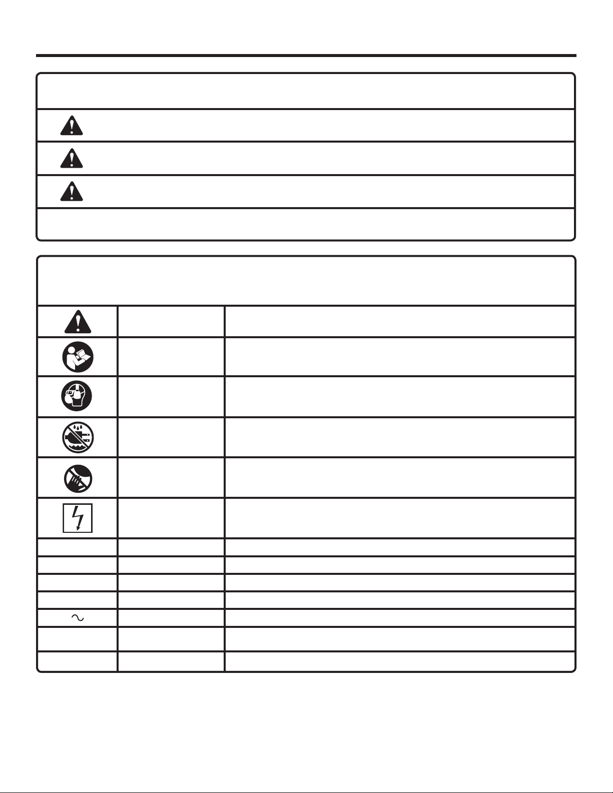
The following signal words and meanings are intended to explain the levels of risk associated with this product.
SYMBOL SIGNAL MEANING
DANGER:
WARNING:
CAUTION:
NOTICE:
Some of the following symbols may be used on this product. Please study them and learn their meaning. Proper
interpretation of these symbols will allow you to operate the product better and safer.
Indicates a hazardous situation, which, if not avoided, will result in death or
serious injury.
Indicates a hazardous situation, which, if not avoided, could result in death or
serious injury.
Indicates a hazardous situation, that, if not avoided, may result in minor or
moderate injury.
(Without Safety Alert Symbol) Indicates information considered important, but
not related to a potential injury (e.g. messages relating to property damage).
SYMBOL NAME DESIGNATION/EXPLANATION
Safety Alert Indicates a potential personal injury hazard.
Read Operator’s
Manual
Eye, Ear, & Breathing Protection
To reduce the risk of injury, user must read and understand operator’s manual
before using this product.
Always wear eye protection with side shields marked to comply with ANSI
Z87.1 along with hearing and breathing protection.
Wet Conditions
Alert
No Hands
Electrocution Failure to properly ground can result in electrocution.
V Volts Voltage
A Amperes Current
Hz Hertz Frequency (cycles per second)
min Minutes Time
Alternating Current Type of current
n
o
.../min Per Minute Revolutions, strokes, surface speed, orbits etc., per minute
No Load Speed Rotational speed, at no load
Do not expose to rain or use in damp locations.
Failure to keep your hands away from the wheel will result in serious personal
injury.
6 — English
ELECTRICAL
EXTENSION CORDS
Use only 3-wire extension cords that have 3-prong grounding plugs and 3-pole receptacles that accept the tool’s plug.
When using a power tool at a considerable distance from
the power source, use an extension cord heavy enough
to carry the current that the tool will draw. An undersized
extension cord will cause a drop in line voltage, resulting in
a loss of power and causing the motor to overheat. Use the
chart provided below to determine the minimum wire size
required in an extension cord. Only round jacketed cords
listed by Underwriter’s Laboratories (UL) should be used.
**Ampere rating (on tool data plate)
0-2.0 2.1-3.4 3.5-5.0 5.1-7.0 7.1-12.0 12.1-16.0
Cord Length Wire Size (A.W.G.)
25' 16 16 16 16 14 14
50' 16 16 16 14 14 12
100' 16 16 14 12 10 —
**Used on 12 gauge - 20 amp circuit.
NOTE: AWG = American Wire Gauge
Always use an extension cord that is designed for outside
use. This is indicated by the letters “W-A” or “W” on the
cord’s jacket.
Before using an extension cord, inspect it for loose or
exposed wires and cut or worn insulation.
Use only extension cords that are intended for outdoor use.
These extension cords are identified by a marking “Acceptable for use with outdoor appliances; store indoors while not
in use”. Use only extension cords having an electrical rating
not less than the rating of the product. Do not use damaged
extension cords. Examine extension cord before using and
replace if damaged. Do not abuse extension cords and do
not yank on any cord to disconnect. Keep cord away from
heat and sharp edges. Always disconnect the extension
cord from the receptacle before disconnecting the product
from the extension cord.
WARNING:
Keep the extension cord clear of the working area.
Position the cord so that it will not get caught on
lumber, tools or other obstructions while you are
working with a power tool. Failure to do so can
result in serious personal injury.
WARNING:
Check extension cords before each use. If damaged
replace immediately. Never use tool with a damaged cord since touching the damaged area could
cause electrical shock resulting in serious injury.
ELECTRICAL CONNECTION
This tool is powered by a precision built electric motor. It
should be connected to a power supply that is 120 V, AC
only (normal household current), 60 Hz. Do not operate
this tool on direct current (DC). A substantial voltage drop
will cause a loss of power and the motor will overheat. If the
saw does not operate when plugged into an outlet, double
check the power supply.
SPEED AND WIRING
The no-load speed of this tool is approximately 3,450 rpm.
This speed is not constant and decreases under a load or
with lower voltage. For voltage, the wiring in a shop is as
important as the motor’s horsepower rating. A line intended
only for lights cannot properly carry a power tool motor. Wire
that is heavy enough for a short distance will be too light for
a greater distance. A line that can support one power tool
may not be able to support two or three tools.
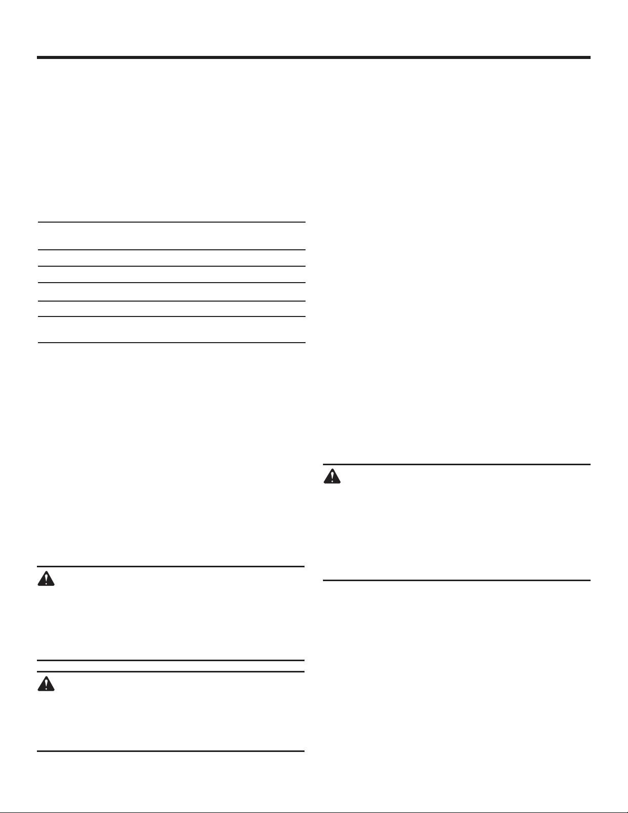
GROUNDING INSTRUCTIONS
See Figure 1.
This tool must be grounded. In the event of a malfunction or
breakdown, grounding provides a path of least resistance
for electric current to reduce the risk of electric shock. This
tool is equipped with an electric cord having an equipmentgrounding conductor and a grounding plug. The plug must be
plugged into a matching outlet that is properly installed and
grounded in accordance with all local codes and ordinances.
Do not modify the plug provided. If it will not fit the outlet,
have the proper outlet installed by a qualified electrician.
WARNING:
Improper installation of the grounding plug can
result in a risk of electric shock. When repair or
replacement of the cord is required, do not connect the grounding wire to either flat blade terminal.
The wire with insulation having an outer surface
that is green with or without yellow stripes is the
grounding wire.
Check with a qualified electrician or service personnel if the
grounding instructions are not completely understood, or if
in doubt as to whether the tool is properly grounded.
Repair or replace a damaged or worn cord immediately.
This product is for use on a nominal 120 volt circuit and
has a grounding plug similar to the plug illustrated in
figure 1. Only connect the product to an outlet having the
same configuration as the plug. Do not use an adapter with
this product.
Ground Fault Circuit Interrupter (GFCI) protection should be
provided on the circuit(s) or outlet(s) to be used for the tile
saw. Outlets are available having built-in GFCI protection
and may be used for this measure of safety.
7 — English
ELECTRICAL
If the saw is used with an extension cord, ensure the connection of the tool’s power cord and the extension cord are
not on the ground.
If a protected outlet is not available, do not use the saw
until an outlet can be changed or auxiliary protection can
be obtained. These auxiliary protection devices are available
at your local retailer.
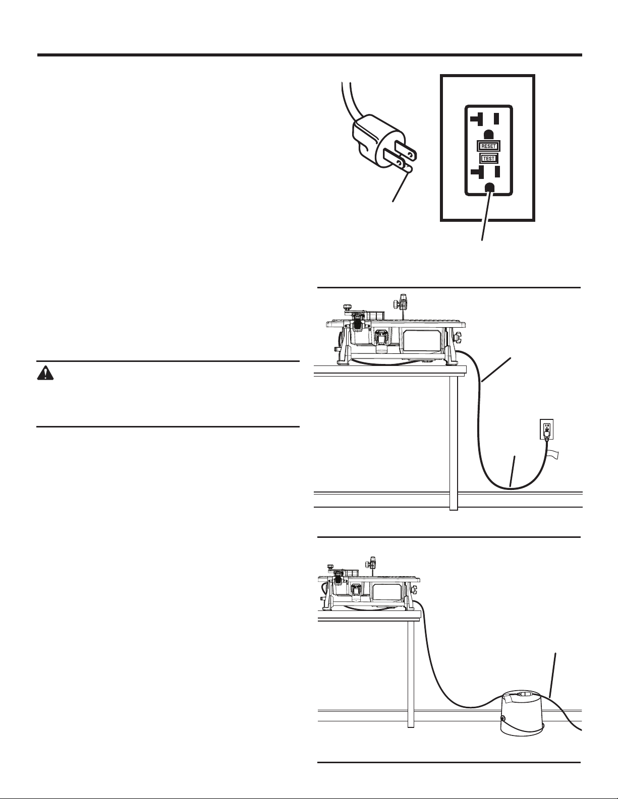
POSITION OF THE TILE SAW
See Figures 2 - 3.
To avoid the possibility of the tool plug or outlet getting
wet, position tile saw to one side of a wall-mounted outlet
to prevent water from dripping onto the outlet or plug. The
operator should arrange a “drip loop” in the cord connecting
the saw to the outlet. The “drip loop” is that part of the cord
below the level of the outlet, or the connector if an extension
cord is used, to prevent water traveling along the cord and
coming in contact with the outlet.
If the plug or outlet does get wet, DO NOT unplug the cord.
Disconnect the fuse or circuit breaker that supplies power
to the tool then unplug and examine for the presence of
water in the outlet.
GROUNDING
PIN
GROUND FAULT
OUTLET
Fig. 1
POWER
CORD
WARNING:
To reduce the risk of electrocution, keep all connections dry and off the ground. Do not touch the
plug with wet hands.
DRIP
LOOP
Fig. 2
EXTENSION
CORD
8 — English
Fig. 3
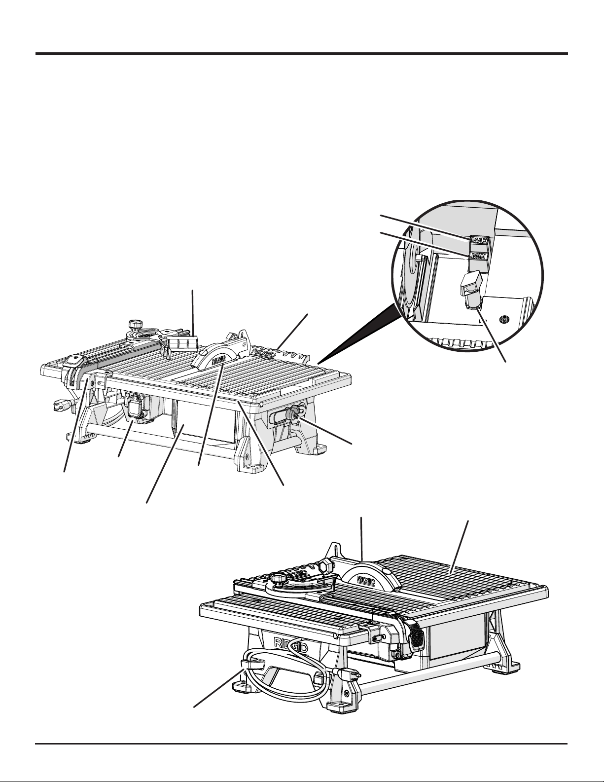
FEATURES
PRODUCT SPECIFICATIONS
Wheel Diameter ............................................................7 in.
Wheel Arbor .............................................................. 5/8 in.
Rip Capacity (tile size) ........ 24 in. (with rear support table)
Diagonal Capacity (tile size) .......................................12 in.
MITER
GUIDE
REAR SUPPORT
Maximum Depth of Cut ......................................... 1-1/4 in.
Rating ..........................................120 V~, 60 Hz, 6.5 Amps
No Load Speed .....................................3,450 r/min. (RPM)
MAX WATER
FILL LINE
MIN WATER
FILL LINE
TABLE
RIP
GUIDE
ON/OFF
SWITCH
RESERVOIR
WATER
TILE CUTTING
WHEEL
RIP GUIDE
SCALE
WRENCH
STORAGE
SPLASH
HOOD
OVERFLOW
DRAIN
BEVEL
TABLE
CORD
STORAGE
Fig. 4
9 — English
FEATURES
KNOW YOUR TILE SAW
See Figure 4.
The safe use of this product requires an understanding of
the information on the tool and in this operator’s manual as
well as a knowledge of the project you are attempting. Before
use of this product, familiarize yourself with all operating
features and safety rules.
7 in. TILE CUTTING WHEEL - A 7 in. tile cutting wheel is
included with your saw.
WARNING:
Do not use wheels rated less than the speed of
this tool. Failure to heed this warning could result
in personal injury.
BEVEL TABLE - Beveled 22.5° and 45° cuts can be made
using the bevel table.
MITER GUIDE - The easy-to-read indicator on the miter
guide shows the exact angle for the desired cut.
MOTOR - This machine has a strong motor with sufficient
power to handle tough cutting jobs.
ON/OFF SWITCH - This saw has an easy access on/off
switch located below the front rail.
REAR SUPPORT TABLE - Helps in supporting larger tiles
up to 24 in. when making rip cuts.
RIP GUIDE - Rip guide is fully adjustable for making cross
cuts and using the miter guide.
SPLASH HOOD - The splash hood helps contain overspray
and mist.
WRENCH STORAGE - The wheel wrench and arbor wrench
may be stored on the side of the tool and secured with a
wing nut.
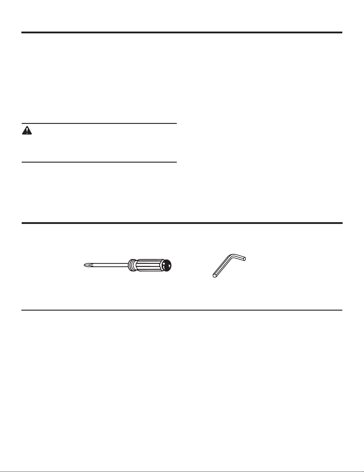
TOOLS NEEDED
The following tool (not included or drawn to scale) are needed for assembly and alignment:
PHILLIPS SCREWDRIVER 2 MM HEX KEY,
3 MM HEX KEY
Fig. 5
10 — English
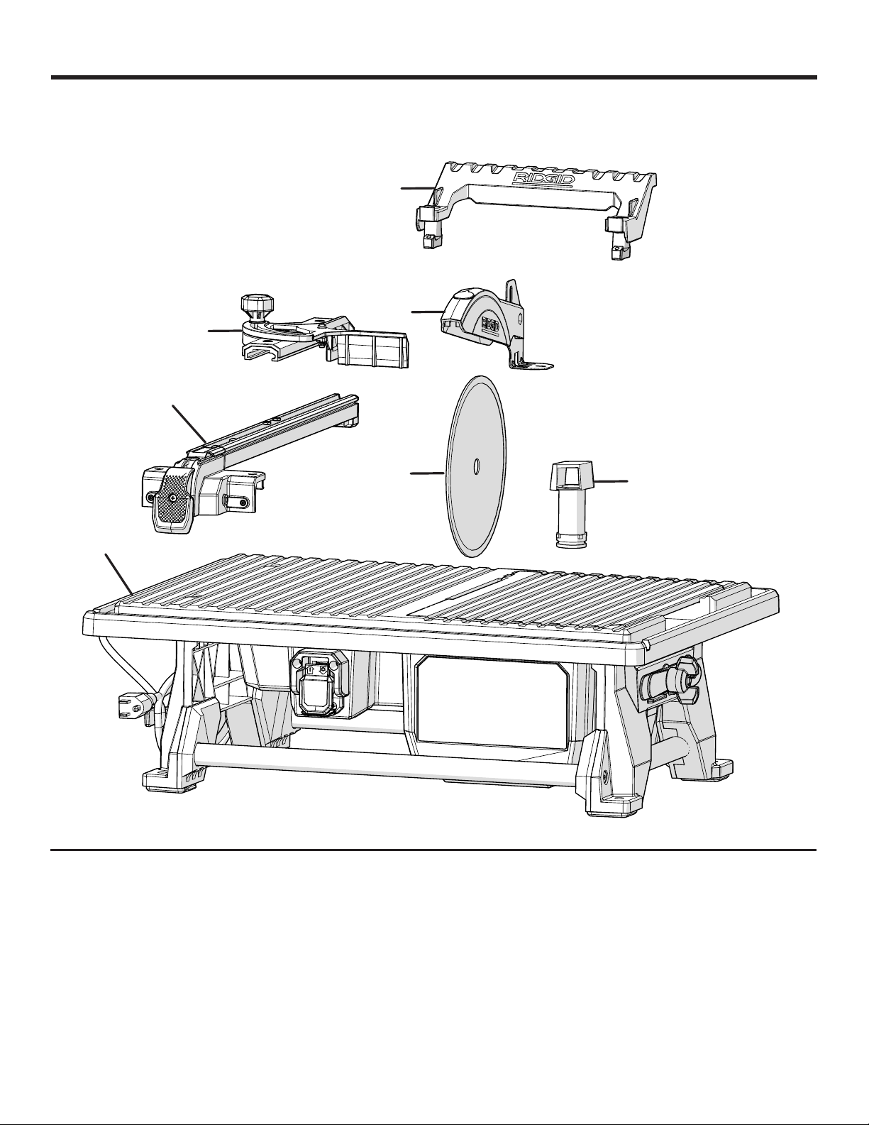
LOOSE PARTS
Most of the Loose Parts shown below are stored in the water reservoir:
G
E
C
B
F
A
A - Tile saw .....................................................................1
B - Rip guide ..................................................................1
C - Miter guide ...............................................................1
D - Overflow drain .........................................................1
D
Fig. 6
E - Splash hood assembly .............................................1
F - Cutting wheel ..........................................................1
G - Rear support table .................................................... 1
11 — English
ASSEMBLYASSEMBLY
UNPACKING
See Figure 6.
This product requires assembly.
Carefully lift the saw from the carton and place on a level
work surface.
WARNING:
Do not use this product if any parts on the Loose
Parts List are already assembled to your product
when you unpack it. Parts on this list are not assembled to the product by the manufacturer and
require customer installation. Use of a product that
may have been improperly assembled could result
in serious personal injury.
Inspect the tool carefully to make sure no breakage or
damage occurred during shipping.
Do not discard the packing material until you have care-
fully inspected and satisfactorily operated the tool.
NOTE: Most of the Loose Parts are stored in the water
reservoir.
The saw is factory set for accurate cutting. After
assembling it, check for accuracy. If shipping has influenced the settings, refer to specific procedures explained
in this manual.
If any parts are damaged or missing, please call
1-866-539-1710 for assistance.
MOUNTING HOLES
The tile saw can be mounted to a firm supporting surface
such as a workbench. Four bolt holes have been provided in
the saw’s base for this purpose. Each of the four mounting
holes should be bolted securely using 3/8 in. machine bolts,
lock washers, and hex nuts (not included). Bolts should be of
sufficient length to accommodate the saw base, lock washers, hex nuts, and the thickness of the workbench. Tighten
all four bolts securely.
Carefully check the workbench after mounting to make
sure that no movement can occur during use. If any tipping,
sliding, or walking is noted, secure the workbench to the
floor before operating.
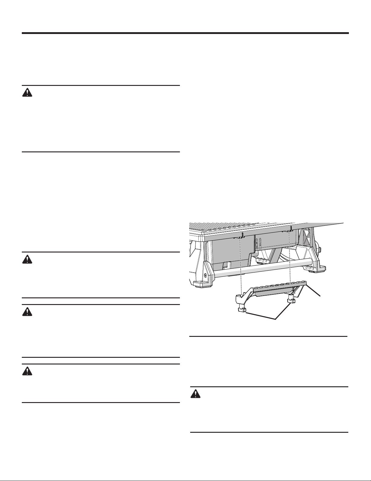
INSTALLING THE REAR SUPPORT TABLE
See Figure 7.
Align the wing screws with the holes located on the back
of the saw, underneath the saw table.
Turn each wing screw until the support table is securely
attached.
WARNING:
If any parts are damaged or missing do not operate this tool until the parts are replaced. Use of
this product with damaged or missing parts could
result in serious personal injury.
WARNING:
Do not attempt to modify this tool or create accessories not recommended for use with this tool. Any
such alteration or modification is misuse and could
result in a hazardous condition leading to possible
serious personal injury.
WARNING:
Do not connect to power supply until assembly is
complete. Failure to comply could result in accidental starting and possible serious personal injury.
REAR SUPPORT
TABLE
WING SCREWS
Fig. 7
TILE CUTTING WHEEL
For maximum performance and safety, it is recommended
that you use the 7 in. cutting wheel provided with your
saw. Additional cutting wheels of the same high quality are
available at your local dealer.
WARNING:
Do not use cutting wheels rated less than the noload speed of this tool. Failure to heed this warning
could result in personal injury. Do not use wheel
with cracks, gaps, or teeth.
12 — English
ASSEMBLY
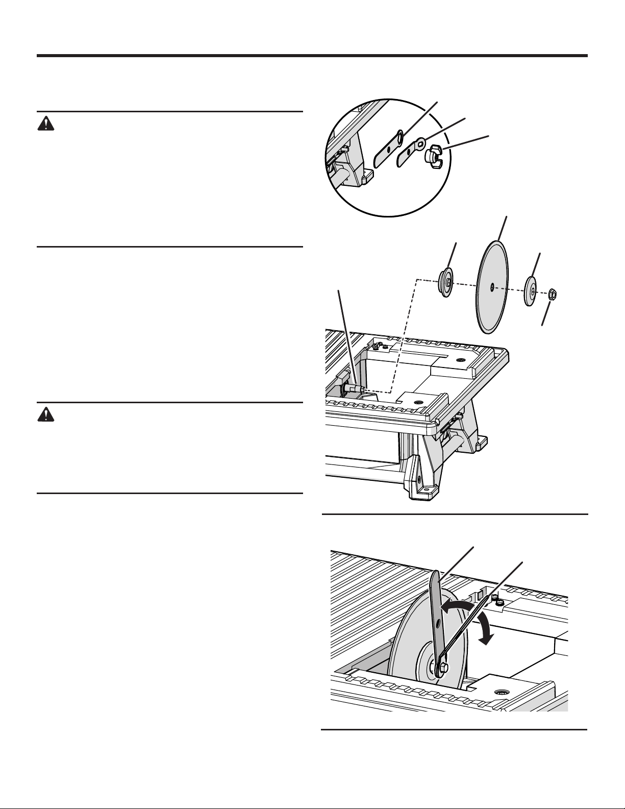
INSTALLING THE TILE CUTTING WHEEL
See Figures 8 - 9.
WARNING:
A 7 in. tile cutting wheel is the maximum wheel
capacit y of the saw. Never use a wheel that is
too thick to allow wheel washer to engage with
the flats on the spindle. Larger wheels will come in
contact with the splash hood, while thicker wheels
will prevent the wheel bolt from securing the wheel
on the spindle. Either of these situations could
result in a serious accident and can cause serious
personal injury.
Unplug the saw and remove the bevel table.
Remove the wing nut and wrenches from the wrench
storage area.
Place the wheel wrench over the arbor nut, and hold the
wheel wrench upright.
Slide the arbor wrench onto the arbor.
Hold the wheel wrench in place and push the arbor wrench
away from you to loosen the arbor nut.
Remove the arbor nut and outer washer, leaving the inner
washer on the arbor.
ARBOR
WHEEL
WRENCH
INNER
WASHER
ARBOR
WRENCH
WING
NUT
CUTTING
WHEEL
OUTER
WASHER
ARBOR
NUT
WARNING:
Always make sure the inner wheel washer is
installed before placing the wheel on the arbor.
Failure to do so could cause an accident, since the
wheel will not tighten properly. Never use wheels
that have openings, grooves, or teeth on this tool.
Place the cutting wheel onto arbor with the arrows on
wheel going in the counterclockwise direction.
NOTE: The cutting wheel must be installed all the way
onto the arbor. Check to see that the wheel spins freely
once installed. It should spin freely, with no side-to-side
movement.
Replace the outer washer. The double “D” flats on the
washers align with the flats on the arbor.
Replace the arbor nut onto the arbor. Hold the wheel
wrench upright and pull the arbor wrench toward you to
tighten the arbor nut.
Return the wrenches and wing nut to the wrench storage
area.
WHEEL
WRENCH
Fig. 8
ARBOR
WRENCH
13 — English
Fig. 9
ASSEMBLY
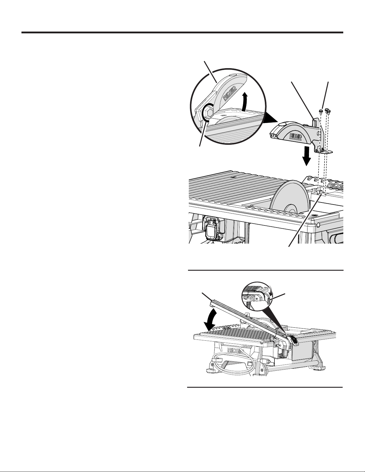
INSTALLING THE SPLASH HOOD
See Figure 10.
Remove the bevel table.
Using a Phillips screwdriver, loosen and remove the three
screws located on the pocket under the table behind the
cutting wheel.
Slide the L-shaped splash hood bracket into the pocket.
Reinstall the screws through the splash hood bracket and
into the table. Tighten securely.
NOTE: Align the hood bracket with the cutting wheel so
that it does not interfere with the material being cut. To
check the alignment, see Splash Hood Bracket Adjust-
ment in the Adjustments section of this manual.
NOTE: Always adjust the splash hood horizontally to the
table and slightly above tile thickness. Hood should not
touch the tile.
To lift or lower the splash hood or adjust its position,
loosen the lock knob, adjust the splash hood to the desired height, and retighten the lock knob.
Reinstall the bevel table.
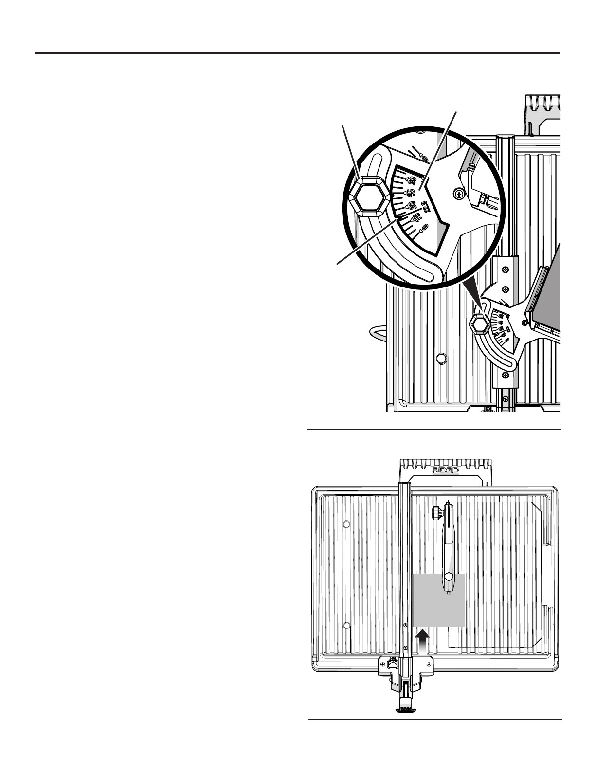
INSTALLING THE RIP GUIDE
See Figure 11.
Place the front of the rip guide on the front rail of the saw
table.
Lower the back of the rip guide to the saw table.
Use the rip guide scale, located on front of the table, to
set the rip guide to the desired width of cut.
Push the locking lever down to secure to the saw table.
When securely locked, the locking lever should point
downward.
SPLASH
HOOD
LOCK
KNOB
RIP
GUIDE
SPLASH HOOD
BRACKET
POCKET
LOCKING
LEVER
SCREWS
Fig. 10
14 — English
Fig. 11
ASSEMBLY
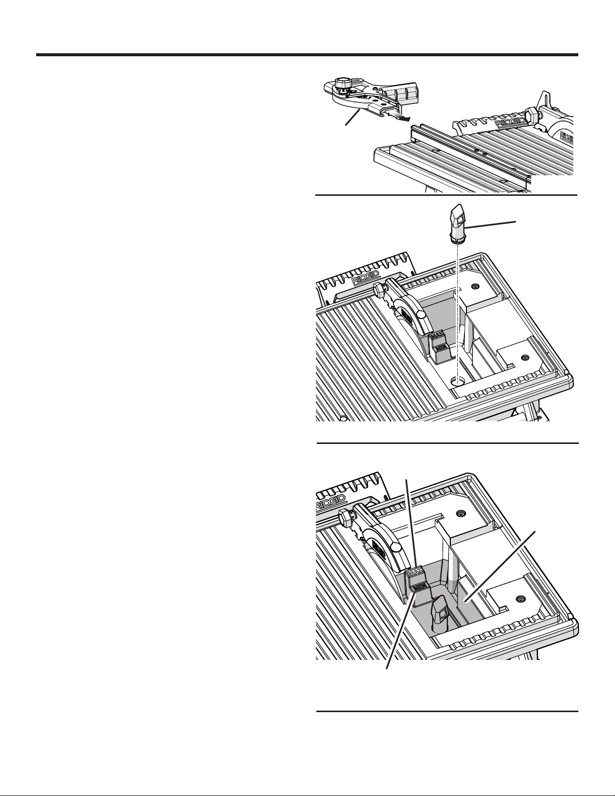
INSTALLING THE MITER GUIDE
See Figure 12.
Align the grooves under the miter guide with the grooves
in the top of the rip guide.
Push the miter guide onto the rip guide to the desired
operating position.
NOTE: Slide the guide off the rip guide to remove.
MITER
GUIDE
INSTALLING THE OVERFLOW DRAIN
See Figure 13.
Firmly push the overflow drain into the hole in the bottom
of the water reservoir.
FILLING/CHANGING THE WATER RESERVOIR
See Figure 14.
The water reservoir must be filled at least to the MIN fill line
and should not be filled past the MAX fill line. Check the
water level periodically and refill as needed.
Fill the water reservoir with clean tap water to the MAX
fill line.
NOTE: The overflow drain prevents overfilling.
To change reservoir water:
Unplug the saw.
Remove the overflow drain and empty waste water into a
bucket. Do not allow the water to splash onto the ground
or around the machine.
Rinse the machine thoroughly.
Discard the waste water in accordance with local regula-
tions.
Replace with clean water.
Fig. 12
OVERFLOW
DRAIN
Fig. 13
MAX FILL
LINE
15 — English
WATER
RESERVOIR
MIN
FILL LINE
Fig. 14
OPERATION
WARNING:
Do not allow familiarity with tools to make you
careless. Remember that a careless fraction of a
second is sufficient to inflict serious injury.
WARNING:
Always wear eye protection with side shields
marked to comply with ANSI Z87.1. Failure to do
so could result in objects being thrown into your
eyes, resulting in possible serious injury.
WARNING:
Do not use any attachments or accessories not
recommended by the manufacturer of this tool.
The use of attachments or accessories not recommended can result in serious personal injury.
APPLICATIONS
You may use this tool for the purposes listed below:
Straight line cutting operations such as cross cutting,
mitering, ripping, and beveling
NOTE: This saw is designed to cut man-made tile, pavers,
and stone tile products only.
WARNING:
In the event of a power failure or when the tool is
not in use, turn the switch OFF. This action will
prevent the tool from accidentally starting when
power returns.
WARNING:
ALWAYS make sure your workpiece is not in contact with the cutting wheel before operating the
switch to start the tool. Failure to heed this warning
may cause the workpiece to be kicked back toward
the operator and result in serious personal injury.
WARNING:
To reduce the risk of accidental starting, ALWAYS
make sure the switch is in the OFF position before
plugging tool into the power source.
SWITCH
ON
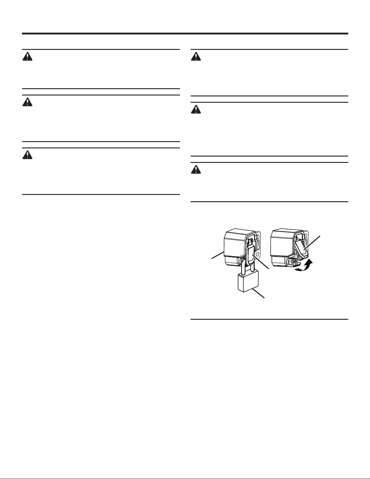
ON/OFF SWITCH
See Figure 15.
This saw is equipped with an on/off switch that has a built-in
locking feature. This feature is intended to prevent unauthorized and possible hazardous use by children and others.
To turn the saw on:
Lift the switch to turn ON.
To turn the saw off:
Press the switch down to turn OFF.
To lock the saw:
With the saw turned OFF, install a padlock (not included)
through the hole in the switch.
ON/OFF
SWITCH
SWITCH
OFF
PADLOCK
Fig. 15
16 — English
OPERATION
USING THE MITER GUIDE
See Figure 16.
To adjust angles:
Install the miter guide onto the rip guide.
Loosen the lock knob and rotate the miter guide until the
angle selector points to the desired angle.
Securely tighten the lock knob.
MAKING CUTS
Always draw the line to be cut on the tile using a marker or
grease pencil. If the tile is shiny and difficult to mark, place
masking tape on the tile and mark the tape.
A common problem when cutting tile is straying from the
marked line. Once you’ve strayed from the mark, you can not
force the wheel back to the line by twisting the tile. Instead,
back up and recut the tile slicing off a small amount of tile
until the wheel is back on track.
To avoid this problem, use the rip guide when making cross
cuts, the miter guide for miter cuts and the bevel table for
making bevel cuts, whenever possible.
Another problem is cutting difficult material. To prevent chipping of the material at the end of the cut: first cut 1-1/2 in.
of the material then turn off the saw; flip the material around
180º and make the cut.
Clean the saw table, rip and miter guides, and bevel table
frequently during use. Debris from the cut material can interfer with tool function.
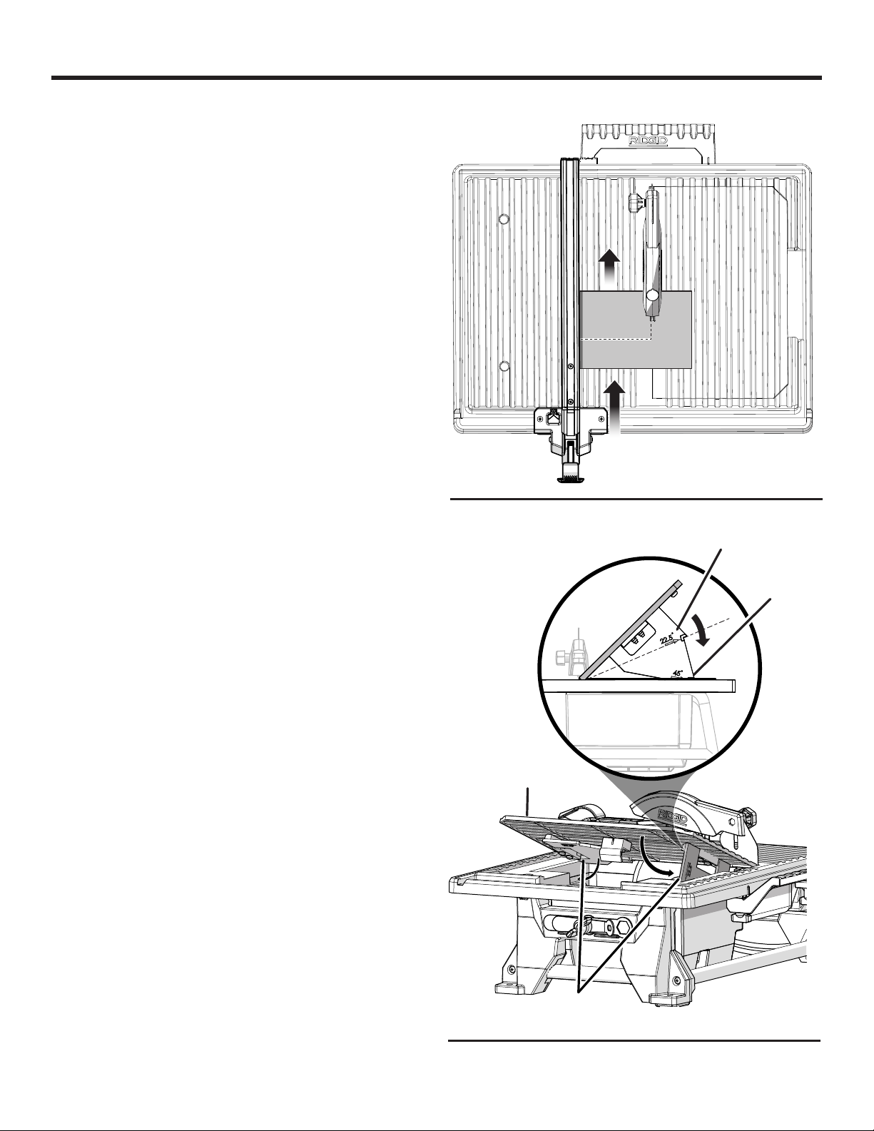
TO MAKE A CROSS CUT
See Figure 17.
Cross cuts are straight 90° cuts. The material is fed into the
cut at a 90° angle to the wheel.
Using a marker or grease pencil, mark the area to be cut
on material.
Remove the miter guide.
Position the rip guide the desired distance from the wheel
for the cut and securely lock the lever.
Place the material on the table and firmly against the rip
guide.
Make sure the material is clear of the cutting wheel before
turning on the saw.
Turn the on/off switch to the ON position.
Let the cutting wheel build up to full speed and wait for
the wheel to get wet before moving the material into the
wheel.
Hold the material firmly against the rip guide and feed
the material into the cutting wheel.
When the cut is made, turn the saw OFF. Wait for the
cutting wheel to come to a complete stop before removing any part of the material.
LOCK
KNOB
ANGLE
SELECTOR
MITER GUIDE
SCALE
Fig. 16
CROSS CUT
17 — English
Fig. 17

OPERATION
TO MAKE A 45° DIAGONAL CUT
See Figure 18.
45° Diagonal cuts are also referred to as “long point-to-long
point cuts”.
Using a marker or grease pencil, mark the area to be cut
on material.
Install the miter guide.
Adjust miter guide to
securely with lock knob.
Position the rip guide the desired distance from the wheel
for the cut and securely lock the lever.
NOTE: For best results when using 12 in. tile, set the rip
guide at 9-3/8 in.
Place the material on the table and firmly against the rip
guide.
Make sure the material is clear of the cutting wheel before
turning on the saw.
Turn the on/off switch to the ON position.
Let the cutting wheel build up to full speed and wait for
the wheel to get wet before moving the material into the
wheel.
Hold the material firmly against the miter guide and slide
miter guide along rip guide. Feed the material into the
cutting wheel.
When the cut is made, turn the saw OFF. Wait for the
cutting wheel to come to a complete stop before removing any part of the material.
using angle scale and tighten
45°
DIAGONAL CUT
Fig. 18
MITER CUT
TO MAKE A MITER CUT
See Figure 19.
Miter cuts are used for cutting outside and inside corners
on material, decorative chair rail, and base molding with
the material at any angle to the wheel other than 90°. Miter
cuts tend to “creep” during cutting. This can be controlled
by holding the workpiece securely against the miter guide.
Using a marker or grease pencil, mark the area to be cut
on material.
Install the miter guide.
Position the rip guide the desired distance from the wheel
for the cut and securely lock the lever.
Set the miter guide to desired angle using the miter guide
scale, and tighten securely with lock knob.
Place the material on the table and firmly against the rip
guide.
Make sure the material is clear of the cutting wheel before
turning on the saw.
Turn the on/off switch to the ON position.
Let the cutting wheel build up to full speed and wait for
the wheel to get wet before moving the material into the
wheel.
Fig. 19
Hold the material firmly against the miter guide and slide
miter guide along rip guide. Feed the material into the
cutting wheel.
When the cut is made, turn the saw OFF. Wait for the
cutting wheel to come to a complete stop before removing any part of the material.
18 — English
OPERATION
TO MAKE AN L-CUT
See Figure 20.
L-cuts are cuts that remove a piece of tile to fit in a corner,
around a cabinet, or a piece of molding and are made by
two separate cuts.
NOTE: Only overcut on the bottom or underneath side of
the material being cut.
Using a marker or grease pencil, mark the area to be cut
on material.
Remove the miter guide.
Position the rip guide the desired distance from the wheel
for the cut and securely lock the lever.
Place the material on the table and firmly against the rip
guide.
Make sure the material is clear of the cutting wheel before
turning on the saw.
Turn the on/off switch to the ON position.
Let the cutting wheel build up to full speed and wait for
the wheel to get wet before moving the material into the
wheel.
Hold the material firmly against the rip guide and feed
the material into the cutting wheel.
Make the cut far enough into the material without over-
cutting.
When the cut is made, turn the saw OFF. Wait for the
cutting wheel to come to a complete stop before removing any part of the material.
Turn the material, adjust the rip guide, and make the
second cut along one of the marks. This time overcut the
other line and the cut piece should separate from the rest
of the material.
When the second cut is made, turn the saw OFF. Wait
for the cutting wheel to come to a complete stop before
removing any part of the material.
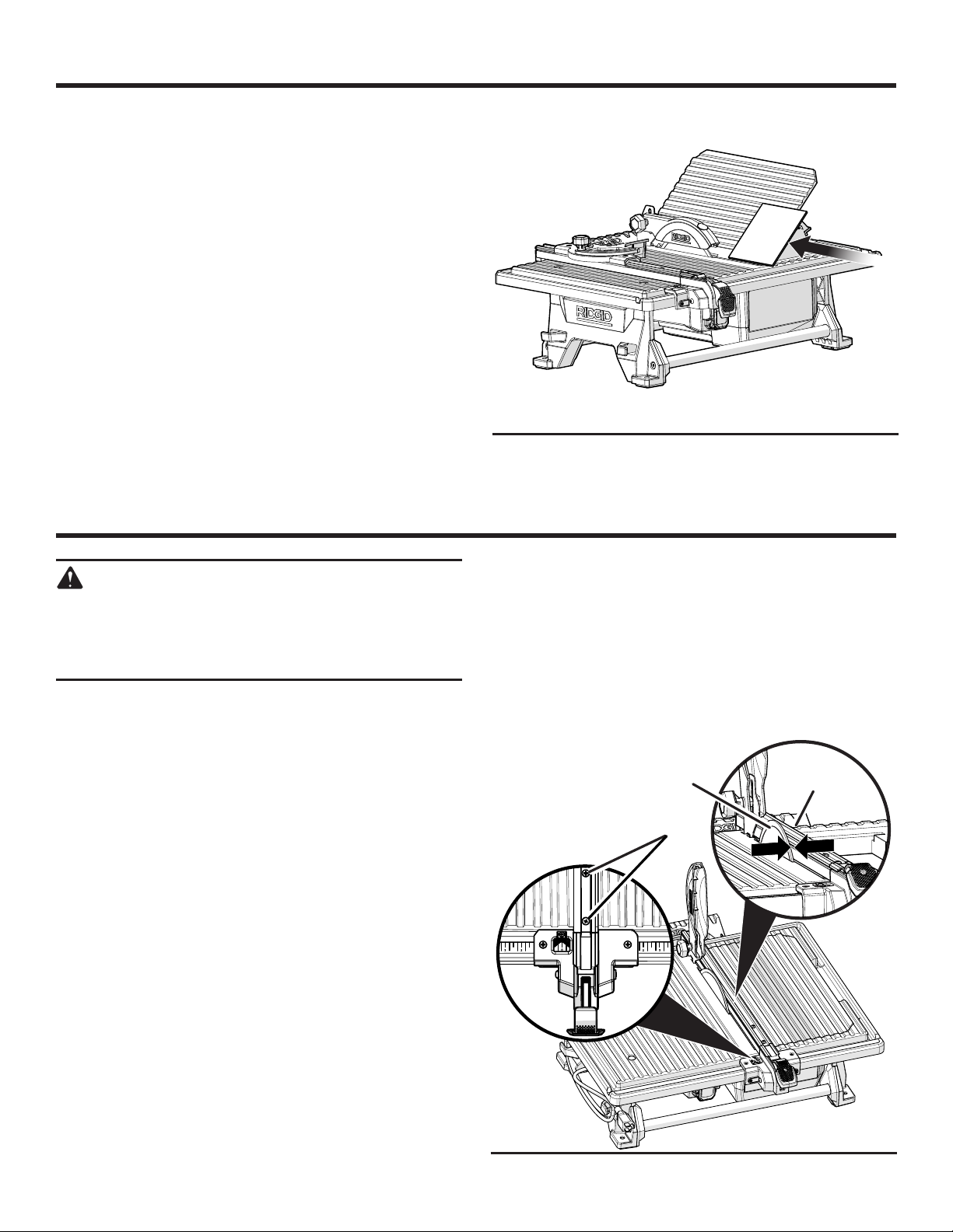
TO MAKE A BEVEL CUT
See Figures 21 - 22.
Beveled 22.5° and 45° cuts can be made using the bevel
table.
Using a marker or grease pencil, mark the area to be cut
on material.
Remove the rip guide.
Tilt the bevel table.
On underside of bevel table, pull down the table legs into
right angles of the plate.
•Use first notches in legs to rest plate at 22.5°
angle.
• Use second set of notches to angle bevel table
at a 45° angle.
NOTE: Make sure bevel table is securely in place
before beginning cut.
19 — English
BEVEL
TABLE
TABLE
LEGS
L-CUT
Fig. 20
22.5º BEVEL
NOTCH
45º BEVEL
NOTCH
Fig. 21
OPERATION
Turn the on/off switch to the ON position.
Let the cutting wheel build up to full speed and wait for
the wheel to get wet before moving the material into the
wheel.
Hold the material firmly against the bevel table and feed
the material into the cutting wheel.
When the cut is made, turn the saw OFF. Wait for the
cutting wheel to come to a complete stop before removing
any part of the material.
ADJUSTMENTS
WARNING:
Before performing any adjustment, make sure the
tool is unplugged from the power supply and the
switch is in the OFF position. Failure to heed this
warning could result in serious personal injury.
BEVEL CUT
Fig. 22
Lock the clamp.
Carefully adjust the rip guide until it is just touching the
cutting wheel. Do not push against the wheel. Adjust the
guide until there are no gaps between the wheel and the
edge of the rip guide.
Tighten the two screws on top of the rip guide.
The saw has been adjusted at the factory for making very
accurate cuts. However, some of the components might
have been jarred out of alignment during shipping. Also,
over a period of time, readjustment will probably become
necessary due to wear.
Do not start any adjustments until you have checked with
a square and made test cuts to be sure adjustments are
needed.
ALIGNING THE RIP GUIDE WITH THE
CUTTING WHEEL
See Figure 23.
For the most accurate results, the rip guide must be aligned
with the cutting wheel.
Unplug the saw.
Make sure the cutting wheel has been correctly installed
on the arbor and the arbor nut has been securely tightened.
Raise the splash hood.
Slightly loosen the two screws on top of the rip guide.
Position the rip guide scale at “0” on the side of the cut-
ting wheel.
CUTTING
WHEEL
SCREWS
RIP
GUIDE
Fig. 23
20 — English
ADJUSTMENTS
SPLASH HOOD BRACKET ADJUSTMENT
See Figure 24.
To check the squareness of the splash hood bracket to the
rip guide, see Aligning the Rip Guide With the Cutting
Wheel earlier in this manual.
When those adjustments have been performed, check the
alignment of the splash hood bracket to the cutting wheel.
Unplug the saw and remove the bevel table.
Raise the splash hood.
Loosen the three bracket screws.
With the rip guide touching the cutting wheel, adjust the
splash hood bracket until it is aligned with the rip guide.
Using a Phillips screwdriver, securely tighten the screws.
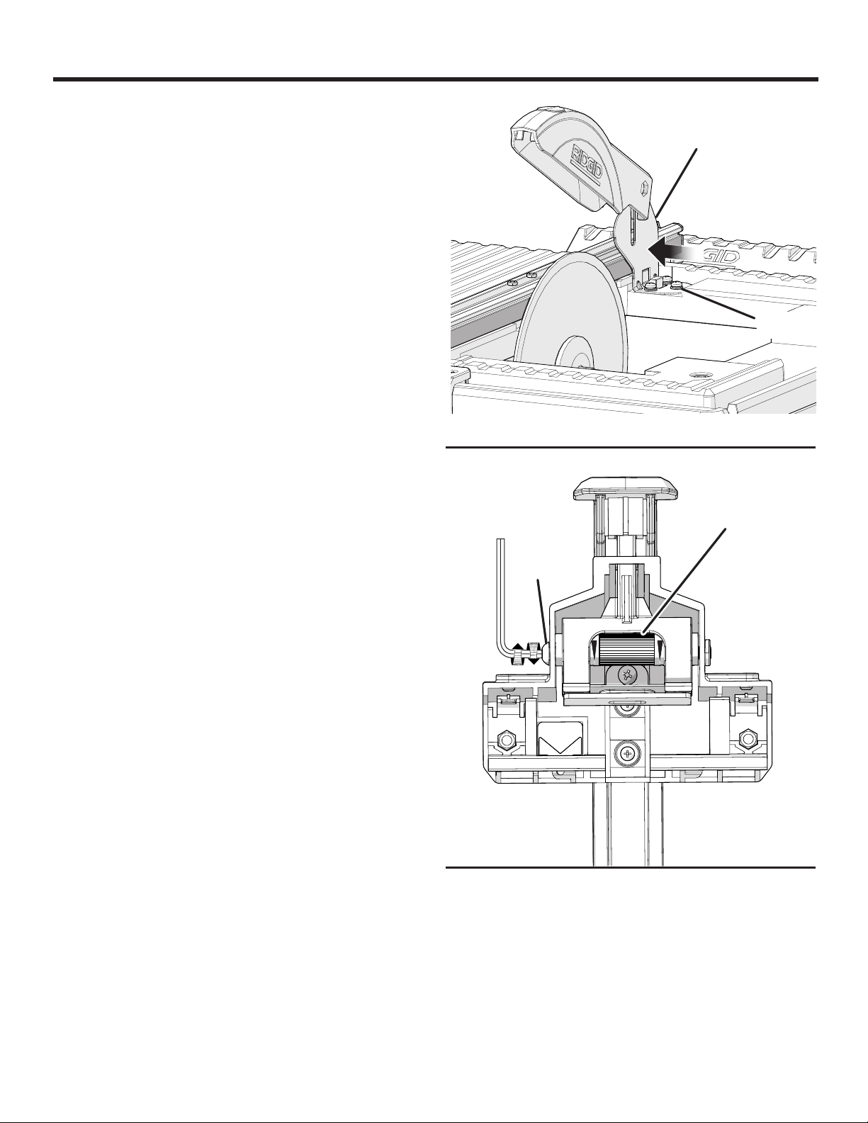
ADJUSTING LOCKING LEVER ASSEMBLY
See Figure 25.
Over time, the rip guide may become loose. If the rip guide
does not lock securely to the saw table, adjustments may
be required.
Unplug the saw and remove the rip guide.
Using a hex key, loosen the cam screw.
Turn the cam to tighten as desired.
NOTE: An arrow is visible on the roller. The wider end of
the arrow is the tighter end of the adjustment. The smaller
end of the arrow is the looser end of the adjustment.
When the desired adjustment is made, tighten the cam
screw securely.
BRACKET
SCREWS
Fig. 24
CAM
CAM
SCREW
21 — English
Fig. 25
ADJUSTMENTS
ADJUSTING RIP GUIDE MOVEMENT
See Figure 26.
If the rip guide does not move smoothly across the rail of the
saw, it may be loosened or tightened using the set screws
on each side of the rip guide.
Unplug the saw.
Using a hex key, loosen or tighten the set screws to
adjust the movement of the rip guide according to your
preference.
Place the rip guide on the rail and check for ease of
movement. Make further adjustments if needed.
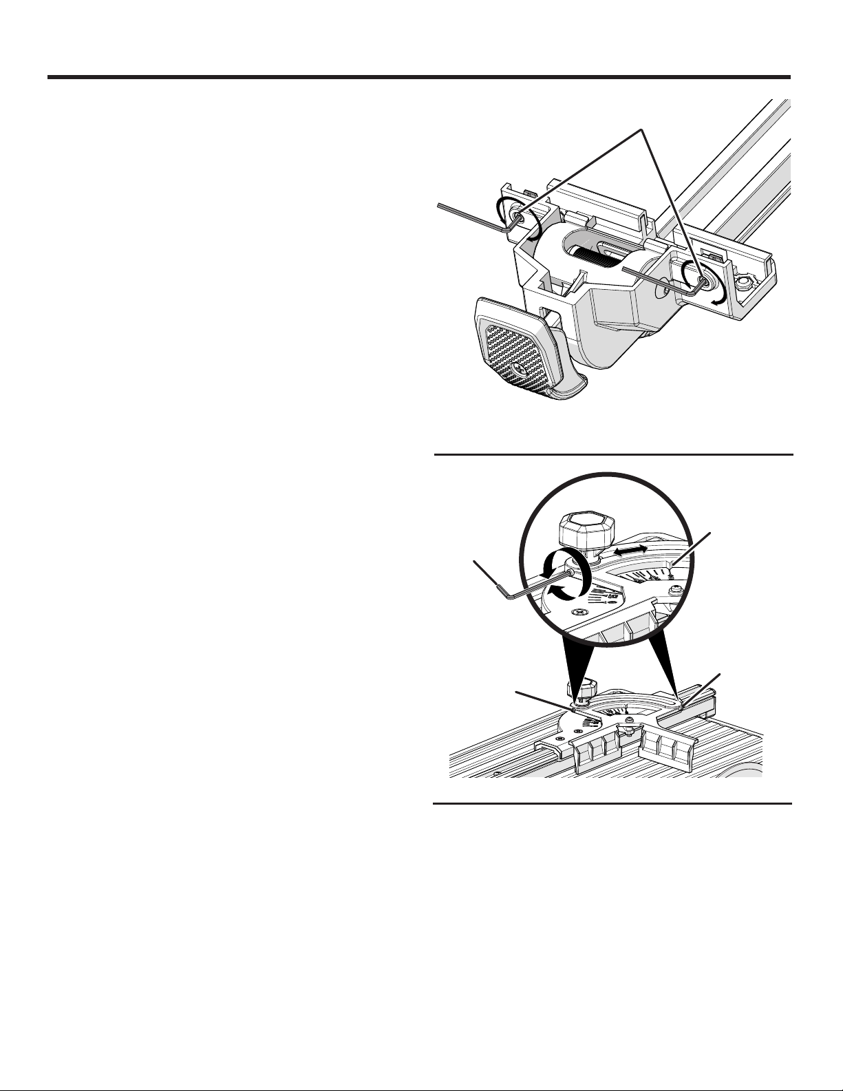
MITER GUIDE ADJUSTMENT
See Figure 27.
With use, the miter guide may require an adjustment to set
the angle selector exactly at “0” on both sides of the miter
guide scale.
Unplug the saw.
Loosen the lock knob and move the angle selector to “0”.
Using a hex key, loosen the set screw on one side of the
miter gauge. Set the angle indicator to “0”.
Tighten the set screw until the proper angle is achieved.
Repeat the above steps on the opposite side of the miter
gauge. Make further adjustments if needed.
SET SCREWS
Fig. 26
ANGLE
INDICATOR
AT “0”
HEX KEY
SET
SCREW
SET
SCREW
Fig. 27
22 — English
 Loading...