

Page 1

Pipe Patch
®
Manual
RIDGID
Pipe Patching
System
• Français– 25
• Castellano – 53
Find Quality Products Online at: [email protected]
www.GlobalTestSupply.com
Page 2

Pipe Patch
Table of Contents
Safety Symbols ............................................................................................................................................................. 2
General Safety Warnings .............................................................................................................................................. 2
Safety Information
Patch Safety ............................................................................................................................................................... 2
RIDGID Contact Information ........................................................................................................................................ 3
Description .................................................................................................................................................................... 3
Specifications ............................................................................................................................................................... 5
Standard Equipment ................................................................................................................................................... 6
Glossary of Common Pipe Patching Terms ............................................................................................................... 6
Pre-Operation Inspection ............................................................................................................................................. 6
Set-up And Operation
Pipe Preparation For Patch ........................................................................................................................................ 7
Installing Packer Sleeve ............................................................................................................................................11
Packer Test Insertion ................................................................................................................................................ 13
Containment
Containment Tube .................................................................................................................................................... 14
Containment Liner .................................................................................................................................................... 15
Preparing The Patch ................................................................................................................................................... 16
Wet Out Patch With Resin ........................................................................................................................................ 17
Pipe Patching .............................................................................................................................................................. 19
Installing Multiple Patches.........................................................................................................................................20
Storage ........................................................................................................................................................................ 20
Maintenance Instructions .......................................................................................................................................... 20
Cleaning ................................................................................................................................................................... 20
Packer Testing .......................................................................................................................................................... 20
Service And Repair ..................................................................................................................................................... 21
Optional Equipment ................................................................................................................................................... 21
Disposal ....................................................................................................................................................................... 21
Pipe Patching Checklist ............................................................................................................................................. 23
*Original Instructions - English
ii
Find Quality Products Online at: [email protected]
www.GlobalTestSupply.com
999-995-411.10_REV A
Page 3
Pipe Patch
®
RIDGID
Pipe Patching
System
WARNING!
Read this Operator’s Manual carefully before using this
tool. Failure to understand
and follow the contents of
this manual may result in
electrical shock, re and/or
serious personal injury.
Find Quality Products Online at: [email protected]
www.GlobalTestSupply.com
Page 4
Pipe Patch
Safety Symbols
In this operator’s manual and on the product, safety symbols and signal words are used to communicate important safety
information. This section is provided to improve understanding of these signal words and symbols.
This is the safety alert symbol. It is used to alert you to potential personal injury hazards. Obey all safety messages that follow
this symbol to avoid possible injury or death.
DANGER
WARNING
CAUTION
NOTICE
NOTICE indicates information that relates to the protection of property.
This symbol means read the operator’s manual carefully before using the equipment. The operator’s manual contains important
information on the safe and proper operation of the equipment.
This symbol means always wear safety glasses with side shields or goggles when handling or using this equipment to reduce
the risk of eye injury.
This symbol means always wear gloves when handling or using this equipment to reduce the risk of injury.
DANGER indicates a hazardous situation which, if not avoided, will result in death or serious injury.
WARNING indicates a hazardous situation which, if not avoided, could result in death or serious injury.
CAUTION indicates a hazardous situation which, if not avoided, could result in minor or moderate injury.
General Safety Warnings
WARNING
Read all safety warnings, instructions, illustrations
and specications provided with this equipment.
Failure to follow all instructions listed below may
result in electric shock, re, and/or serious injury.
SAVE ALL WARNINGS AND INSTRUCTIONS
FOR FUTURE REFERENCE!
• Keep work area clean and well lit. Cluttered or dark
areas invite accidents.
• Do not operate equipment in explosive atmospheres, such as in the presence of flammable
liquids, gases, or dust. Equipment may create sparks
which may ignite the dust or fumes.
ance at all times. Whis enables better control of the
equipment in unexpected situations.
• Do not let familiarity gained from frequent use of
equipment allow you to become complacent and
ignore safety principles. A careless action can cause
severe injury within a fraction of a second.
Safety Information
WARNING
This section contains important safety information
that is specic to this equipment.
Read these precautions carefully before using the
Pipe Patch to reduce the risk of chemical burns or
other serious personal injury.
• Keep children and by-standers away while operating equipment. Distractions can cause you to lose
SAVE ALL WARNINGS AND INSTRUCTIONS
FOR FUTURE REFERENCE!
control.
Keep this manual with the pipe patch for use by the
• Avoid body contact with earthed or grounded
operator.
surfaces such as pipes, radiators, ranges and
refrigerators. There is an increased risk of electrical
shock if your body is earthed or grounded.
• Stay alert, watch what you are doing and use
common sense when operating equipment. Do
not use equipment while you are tired or under the
influence of drugs, alcohol, or medication. A moment
of inattention while operating equipment may result in
serious personal injury.
• Do not overreach. Keep proper footing and bal-
Pipe Patch Safety
• Always wear appropriate personal protective
equipment. Appropriate personal protective equip-
ment always includes safety glasses and chemical
resistant gloves and may include equipment such as
face shields, long sleeves, safety shoes, hard hat, and
respirator as appropriate. This will reduce the risk of
injury.
– Patch resin fumes may irritate the skin and lungs
or damage the eyes. Refer to the resin labeling and
SDS for more information.
2
Find Quality Products Online at: [email protected]
www.GlobalTestSupply.com
999-995-411.10_REV A
Page 5
Pipe Patch
– Drains may contain chemicals, bacteria and other
substances that may be toxic, infectious, cause
burns or other issues.
• Mix resin and wet out patch in a well-ventilated
area. This reduces the risk of irritation or reactions from
resin fumes.
• Do not leave mixed resin in container. Chemical
reactions during curing generate heat. If kept in the
container, that heat could damage the container and
cause burns. Empty all mixed resin onto patch and
spread out. Excess resin can be left to dry on the
protective table covering.
• Do not inflate the packer outside of an appropriately sized pipe. Do not inflate the packer without
packer sleeve/patch/appropriate containment on the
packer per these instructions. This will reduce the
risk of the equipment bursting and causing serious
damage or injury.
• Do not over-pressurize the equipment. This will
reduce the risk of the equipment bursting and causing
serious damage or injury.
• Use proper equipment and patch combinations.
Improper combinations can result in an incomplete
patch which increases the risk of leaks, equipment
damage and injury.
• Practice good hygiene. Do not eat or smoke while
handling or operating the equipment or material.
After handling or operating equipment, use hot,
soapy water to wash hands and other body parts
exposed to chemicals or drain contents. This will
help reduce the risk of health hazards due to exposure
to toxic material.
• Do not use if there is the risk of contact with other
utilities (such as natural gas or electric) during
operation. Crossbores, improperly placed utilities
and damaged drains could allow the equipment to
contact and damage the utility. This could cause
electrical shock, gas leaks, fire, explosion or other
serious damage or injury.
• Follow all applicable codes and regulations. Do
not use if prohibited by local code. This resin is not
approved for use in the City of Los Angeles, CA.
• Before operating the RIDGID Pipe Patch equipment, read and understand:
– This operator’s manual.
– The SDS and labeling for the resin components.
– The instructions and warnings for any other equip-
ment or material being used.
Failure to follow all instructions and warnings may
result in property damage and/or serious injury.
RIDGID® Contact Information
If you have any question concerning this RIDGID product:
– Contact your local RIDGID® distributor.
Description
The RIDGID® Pipe Patching System is a trenchless pipe
repair and relining system. The system repairs cracks,
holes, joint separation and other damage in a variety of
pipe types, such as clay, concrete, cast iron or PVC.
The system uses a cylinderical fiberglass patch wet out
with silicate resin. The patch is mounted on the inflatable
installation tool (the “packer”) and placed at the point of
repair by pushrod or ropes. The packer is inflated to press
the patch inside the repair point. When the resin is hardened, it creates a seal in the damaged area.
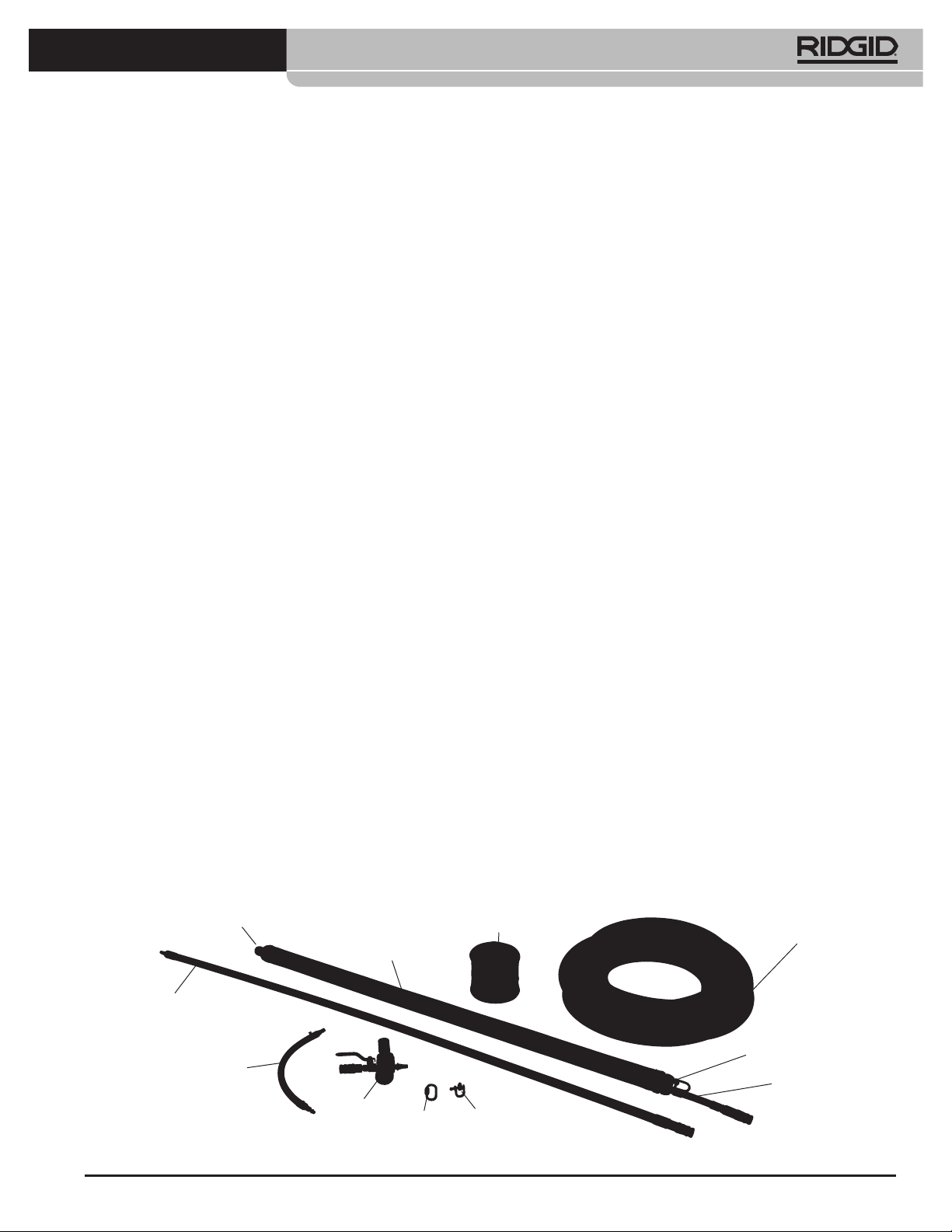
Packer Ball
Packer
Air Push Rod
Standard To Lockable
Air Connector Adapter
Regulator
Figure 1 – RIDGID Pipe Patch Equipment
999-995-411.10_REV A
Find Quality Products Online at: [email protected]
www.GlobalTestSupply.com
Quick
Link
Pull Rope
D-Ring
Patcher Air
Hose
Pull Rope Connection Point
Flexible
Adapter
3
Page 6
Pipe Patch
A variety of packers are available for different pipe sizes
and patch lengths. See Specifications.
All pipe patch pneumatic equipment includes a special
locking connector to reduce the risk of the connections
coming apart during use.
This product is NOT suitable for use in potable water
systems and is not for use in the City of Los Angeles.
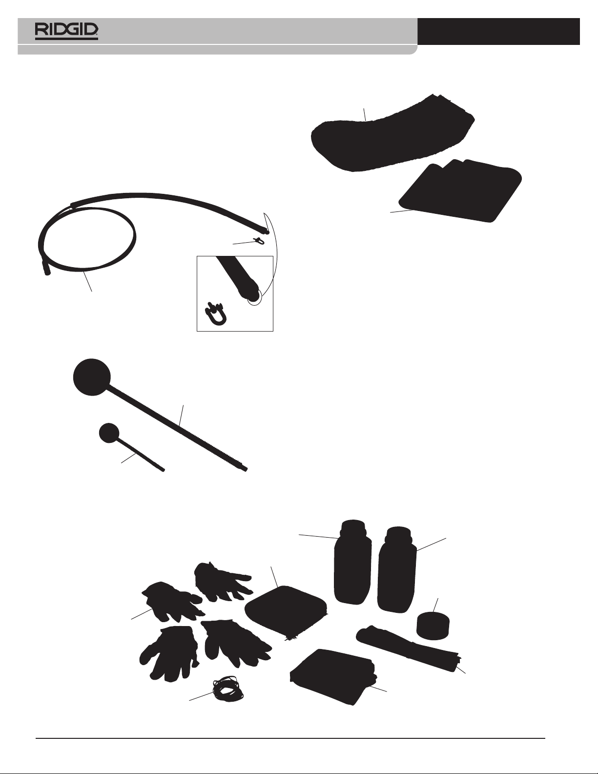
Packer
Ball
D-Ring
Air Push Rod
Figure 2 – 2" Packer With Integral Push Hose
Containment Liner
(Loop Stitch Material)
Containment Tube
Figure 5 – Containment Kit Materials
for 3" - 4", 4" - 6"
for 2"and 3"
Figure 3 – Ball and Spring Leader Guide (Optional
Accessories)
Gloves
Patch Resin Part A
Patch
Patch Resin Part B
Tape
Packer Sleeves
Pipe Patch Elastic Bands
Table Covering
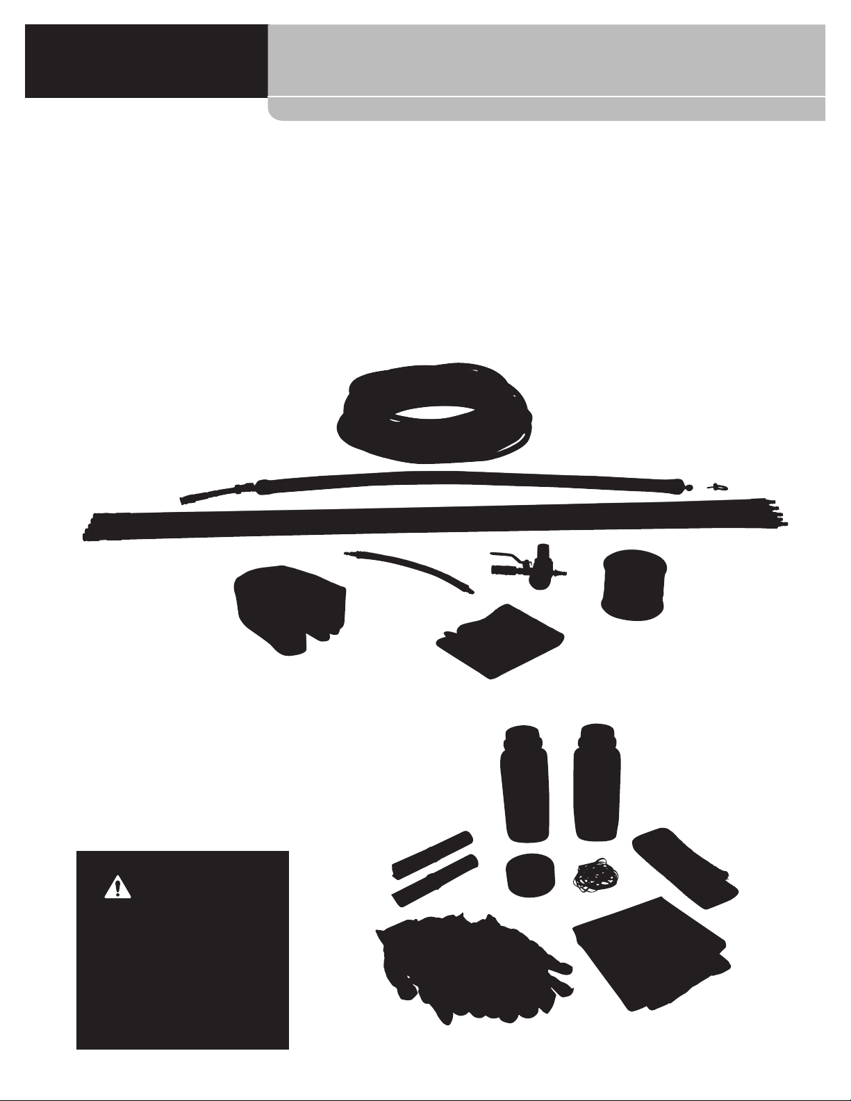
Figure 4 – RIDGID Pipe Patch Kit General Contents
4
Find Quality Products Online at: [email protected]
www.GlobalTestSupply.com
999-995-411.10_REV A
Page 7
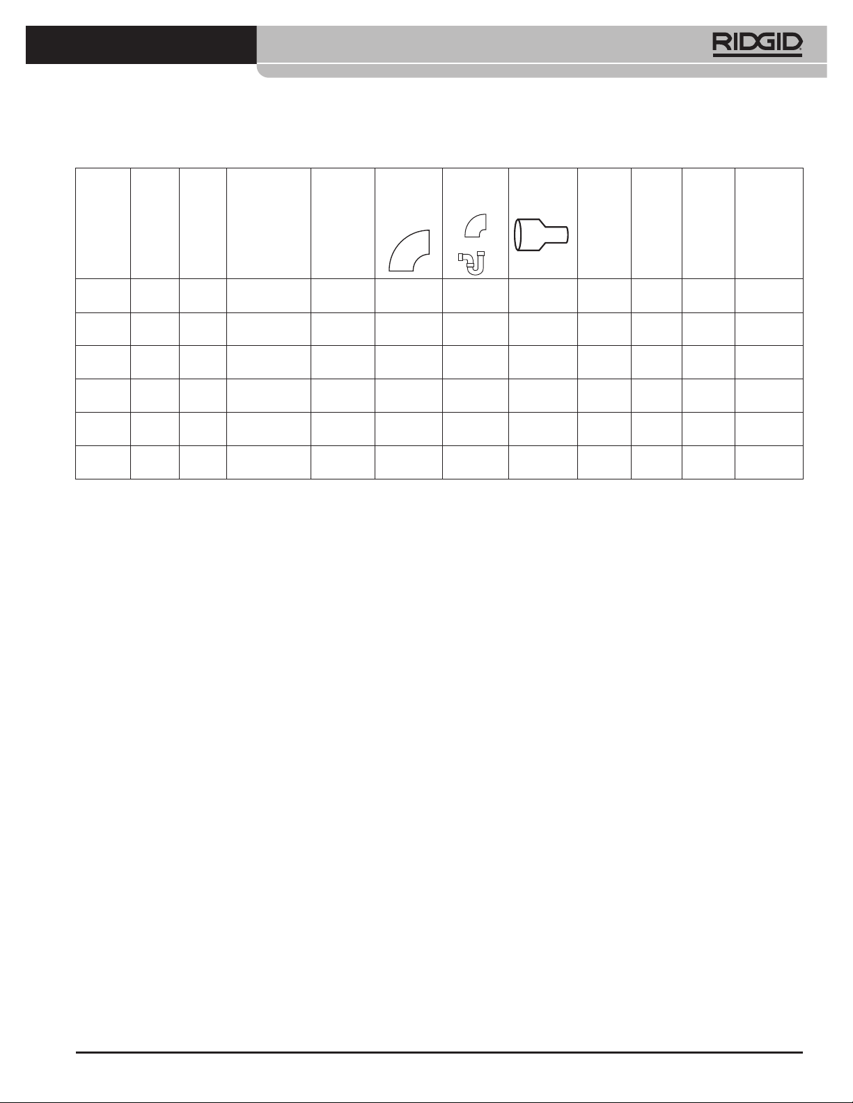
Specications
Pipe Patch Installation Equipment
Packer/
Nominal
Pipe Ø
Overall
Packer
Length
Max.
Patch
Length
Minimum
Encroachment
Zone**
Packer
Operating
Pressure*
22°, 45°,
Long
Radius 90°
Elbows
Short
Radius 90°
Elbows
and P-Trap
Pipe Size
Transitions
Air Push
Rods
Pipe Patch
Resin
Amount
Wet Out
Resin
Pipe Patch
Elastic
Bands
2" 43" 32" 3" 43 psi Y Y N 10'
3" 43" 32" 3" 60 psi Y Y N 5'
3" - 4" 4' 36" 5" 50 psi Y 4" Only 3" - 4" 5'
3" - 4" 7' 68" 5" 50 psi Y 4" Only 3" - 4" 5'
4" - 6" 4' 36" 5" 36 psi Y 6" Only 4" - 6" 5'
4" - 6" 7' 68" 5" 36 psi Y 6" Only 4" - 6" 5'
* Do not exceed packer operating pressure
** Minimum amount of exposed packer rubber at end of patch required for proper installation of patch.
Air Push Rod (For use with 3" and larger packers)
Nominal
Length ........................ 5' (1.5 m) each
Maximum
Reach ......................... 100' (30.5 m)
Maximum
Pipe Patch Specifications
Pipe patch kits are available for a variety of inner pipe diameters in various lengths. Refer to the RIDGID catalog
for specific offerings.
Patch Material ..............Fiberglass
Resin Type ...................Two-Component Organic Silicate
Pressure ..................... 217 PSI (15 Bar)
Not for use through P-traps or 3" elbows
Air Hose Length ........... 100’ (30.5 m)
Resin Mix
Ratio ............................. 2:1 by volume, Controlled by
Pneumatic Connector
Type .............................. Locking
Adapter .........................Adapts standard air hose con-
nectors to locking style used with
Resin Shelf Life ............One Year, Use By Date On
RIDGID pipe patching equipment
Required Compressed Air
Supply ..........................100 psi to 130 psi (6.9 to 9.0 Bar)
Resin Storage
Temperature .................41°F to 113°F (5°C to 45°C) Do
Pull Rope ......................750 pound (3.3 kN) rating,
¼" (6.4mm) Diameter, 250’ (76 m)
Long
Gloves ..........................Nitrile
2" RIDGID Pipe Patch
Resin Application
Temperature ................41°F to 68° F (5°C to 20°C)
Working Time
(Pot Life) ....................... 15 Minutes (At Resin Application
Elastic Bands ............... Specially sized for use with
RIDGID 2" packer
Resin Set Time ............90 Minutes (Internal Pipe Tem-
3" - 6" RIDGID Pipe Patch
Elastic Bands ............... Specially sized for use with
RIDGID 3" to 6" packers
180 Minutes (Internal Pipe Tem-
Integral
Sections
Sections
Sections
Sections
Sections
32" Off
Packer
32" On
Packer
3' On
Packer
2 x 3' On
Packer
3' Off
Packer
2 x 3' Off
Packer
Mineral
Containers. Make sure both containers are marked the same (32"
or 3')
Carton/Resin Container
not allow resin to freeze
Temperature)
perature 50F° to 68°F (10°C to
20°C))
perature 41°F to 49°F (5° to 9°C))
2"
3" - 6"
3" - 6"
3" - 6"
3" - 6"
3" - 6"
999-995-411.10_REV A
Find Quality Products Online at: [email protected]
www.GlobalTestSupply.com
5
Page 8

Pipe Patch
Final Hardness
Time .................. 240 Minutes (If Pressure Testing)
Typical patch
thickness ........... 0.16” (4 mm)
This product is NOT suitable for use in potable water
applications and is not for use in the City of Los Angeles.
Standard Equipment
Refer to the RIDGID catalog for details on equipment
supplied with specific catalog numbers.
NOTICE
pair pipes. If properly used, it should not further damage
pipe that is being repaired. Pipe patching may not work
in all instances. Improper use of the pipe patching system
may obstruct the pipe. It may be necessary to access the
damage by digging or other methods to properly fix the
pipe damage.
This pipe patching system is designed to re-
Glossary of Common Pipe
Patching Terms
Containment
Liner ...................The restrictive liner used to prevent the
packer from over inflating in sections of
pipe with bends.
Containment
Tube ...................The restrictive tube used to prevent the
packer from over inflating in straight sections of pipe.
Encroachment
Zone ...................The area at each end of the packer that
will not expand to the full to the pipe diameter when inflated. The patch CANNOT be in this zone. If the patch is in this
zone, the patch will not be proper and
may block the pipe. The encroachment
zone is measured from the point where
the black rubber meets the metal end of
the packer. This zone is 3" long for the 2"
& 3" packers and 5” long for the 3"-4" &
4"-6" packers.
Final Hardness Time (Also Known As
“Cure Time”) .......The time at which the patch has reached
its full hardness and is as strong as it will
get.
Flexible
Adapter ...............The short flexible air fitting assembly
located at the back end of the packer
which the Air Push Rod or the Patching
Air Hose connect to.
Internal Pipe
Temperature .......The temperature inside the pipe to be
patched, at the area to be patched. Higher temperatures decrease resin set time,
lower temperatures increase set time.
Packer ................The inflatable bladder used to inflate and
hold the patch in place against the inside
of the pipe while the patch hardens and
cures.
Packer Sleeve ....The clear protective sleeve used to cover
the packer and prevent contact with the
resin.
Packer Test Insertion (Also Known As A
“Dry Run”) ..........The process of ensuring that the packer
is able to navigate the pipe to the point
of repair. During the test insertion, the
packer should have a packer sleeve installed on it to protect the packer and
packer sleeve is lubricated with oil soap
to simulate the resin.
Patching Air
Hose ...................Used in place of the push rods and at-
tached to the air fitting on the packer
when pulling the packer into place.
Resin Set
Time ...................The time required for the resin to suffi-
ciently harden to allow the packer to be
deflated and removed. Resin set time is
temperature dependent. At this time, the
pipe can be put back into service.
Pre-Operation Inspection
WARNING
Before each use, inspect your pipe patching system and correct any problems to reduce the risk of
serious injury from chemical burns, infections and
other causes and prevent system damage.
Always wear safety glasses, and other appropriate
protective equipment.
1. Clean the equipment to be used to aid inspection and
improve control during use.
2. Inspect the pipe patch equipment for the following
items:
• Proper assembly and completeness.
6
Find Quality Products Online at: [email protected]
www.GlobalTestSupply.com
999-995-411.10_REV A
Page 9

Pipe Patch
• Wear and damage, look for kinks, cuts, cracks and
breaks.
• Any condition which may prevent safe and normal
operation.
If any problems are found, do not use the equipment
until the problems have been repaired or the parts
replaced.
3. Inspect pull rope for wear and damage that could
reduce its strength.
4. Inspect the patch kit components. Make sure all
components are present and in good condition.
Confirm the resin “use by” date is current and not
expired (See Figure 6).
Resin Use By Date
Figure 6 – Resin Use By Date
5. Inspect and maintain any other equipment being
used per its instructions to make sure it is functioning
properly.
Set-up And Operation
WARNING
Follow all instructions and warnings for resins.
Refer to the resin labeling and SDS for more information. This will help reduce the risk of health
hazards due to exposure to resin material.
Do not leave mixed resin in container. Chemical reactions during curing generate heat. If kept in the
container, that heat could damage the container
and cause burns. Empty all mixed resin onto patch
and spread out. Excess resin can be left to dry on
the protective table covering.
Do not inate the packer outside of an appropriately sized pipe. Do not inate the packer without
packer sleeve/patch/appropriate containment on
the packer per these instructions. This will reduce
the risk of the equipment bursting and causing
serious damage or injury.
Do not over-pressurize the equipment. This will
reduce the risk of the equipment bursting and
causing serious damage or injury.
Follow setup and operating instructions to reduce
the risk of injury from chemical burns, infections
and other causes, and prevent system damage.
1. Check work area for:
• Adequate lighting.
• Place out of direct sunlight for mixing resin, near
the point of insertion in the pipe.
• Clear, level, stable, dry location for all equipment
and operator.
• Confirm that there is sufficient ventilation. When
working indoors, windows may need to be opened
and/or powered ventilation may be needed to
remove resin fumes.
• Clear path between patch wet out area and point
of insertion in pipe.
2. Make sure all equipment has been properly inspected.
Proper pipe patch installation is dependent on preparation and timing. Figure 7 shows the general pipe patching
steps. Every Pipe Patching job is different and requires
Always wear appropriate personal protective equipment. Appropriate personal protective equipment
always includes safety glasses and chemical resistant gloves and may include equipment such as
face shields, long sleeves, safety shoes, hard hat,
and respirator as appropriate. This will reduce the
risk of injury.
Pipe patching resin fumes may irritate the skin
and lungs or damage the eyes. Refer to the resin
labeling and SDS for more information.
Drains may contain chemicals, bacteria and other
substances that may be toxic, infectious, cause
burns or other issues.
Mix resin and wet out patch in a well-ventilated
area. This reduces the risk of irritation or reactions
from resin fumes.
999-995-411.10_REV A
Find Quality Products Online at: [email protected]
www.GlobalTestSupply.com
the installer to exercise good judgment and follow industry best practices. Every jobsite is different and requires
the skill and good judgment of the installer to choose
proper methods and practices. A checklist is provided at
the end of this manual to help ensure that all steps are
completed.
7
Page 10

Pipe Patch
1 2
INSPECT THE LINE TO INVESTIGATE THE DAMAGE CLEAR ALL BLOCKAGES AND CLEAN THE LINE WALL-TO-WALL
3 4
RE-INSPECT THE LINE TO ENSURE IT IS FREE OF DEBRIS AND
CONFIRM LOCATION AND SIZE OF REPAIR
5 6
PREPARE THE PATCH AND POSITION THE PACKER IN
THE PROPER LOCATION
7 8
ONCE RESIN IS CURED, DEPRESSURIZE THE PACKER REMOVE THE PACKER
Figure 7 – Generalized Pipe Patching Steps (Sleeve/Containment Not Shown, Patch Position Shifted For Clarity)
Pipe Preparation For Patch
ENSURE PACKER CAN BE NAVIGATED TO THE PATCH LOCATION BY
PERFORMING A TEST INSERTION
INFLATE THE PACKER TO THE REQUIRED PRESSURE.
ALLOW THE RESIN TO CURE FOR THE RESIN SET TIME
– The diameter and length of the patch that is
needed. If needed, multiple patches can be
1
applied for longer repairs. See Installing Multiple
Patches section.
– The pipe in the area to be patched should be
mostly round.
– If the packer will be placed such that portions
INSPECT THE LINE TO INVESTIGATE THE DAMAGE
of the packer will be unsupported. This would
include:
• Openings over 1" in diameter (such as T’s or
1. Use video inspection camera equipment (“camera”)
and determine:
• The location and nature of the pipe damage and
• The packer extending into a larger size pipe or
pipe damage).
out of the drain.
required patch (Figure 7-1).
8
Find Quality Products Online at: [email protected]
www.GlobalTestSupply.com
999-995-411.10_REV A
Page 11

Pipe Patch
If the packer is not properly supported, the patch
can bulge into the unsupported area and/or the
packer can be damaged or burst. In these cases,
the proper containment material must be used
(see “Containment” section).
• Pipe size(s), type(s), transitions, traps, shifted pipe
and other obstacles present that could prevent
packer insertion or cause damage. The transitions
in pipe system may require a smaller size packer.
• Best access to area to be patched. In some cases,
it may be necessary to have access on both ends
of the pipe to be patched to allow the packer to be
pulled into position. Determine how the packer will
be moved into position. A test insertion is required
to confirm that the packer can be placed properly.
• Visual inspection of the pipe is required. Multiple
visual inspections will be required throughout the
patching process. While inspecting, determine
the temperature of the pipe to be patched. If the
pipe is hotter or cooler than the resin application
temperature (41°F to 68°F (5°C to 20°C)), the resin
set time will be affected. Lower temperatures will
increase set time and higher temperatures may
decrease set time.
2
CLEAR ALL BLOCKAGES AND CLEAN THE LINE WALL-TO-WALL
2. Thoroughly clean the pipe system. Remove all debris,
roots and other materials that can block the movement of packer into place or damage the pipe patch
and equipment inside pipe. (Figure 7-2). Pipe should
be cleaned to the pipe base material. When working
in PVC or other plastic pipe, in addition to cleaning
to the base material, the cleaning method needs to
“roughen up” the base material. This “roughening up”
helps to provide mechanical bonding of the patch to
the pipe.
Clean past the damage to allow water and debris
to drain from the area. Area should be flushed and
fluid flow shut off. Pipe can be patched with small
amounts of water in the drain, but less water in the
area is better. While the drain does not need to be
perfectly clean, any material left in the drain may
make the patching process more difficult and prevent
proper sealing.
3
RE-INSPECT THE LINE TO ENSURE IT IS FREE OF DEBRIS AND
CONFIRM LOCATION AND SIZE OF REPAIR
3. Reinspect the drain with the camera. Confirm that the
drain is properly cleaned and meets the requirements
for patching. Ensure that the pipe is free of sharp
features that could damage the packer, such as
broken sections of pipe. Position the camera head
at the center of the damaged area to be patched
and mark the camera push cable (for example with
tape around the push cable, See Figure 8) near the
pipe entrance. This will be used to determine the
measurement to the damaged area for patching. See
Figure 7-3.
4. In an open area, layout the camera push cable so that
the mark on the push cable is visible. Measure the
distance from the camera head (patch location) to the
mark on the camera push cable to confirm how far into
the drain the patch will be placed. See Figure 8.
5. Determine if the packer will be put in place using the
air push rod, a pull rope, or a combination of both. A
pull rope is always used at the same end as the air
push rod. If using a second pull rope from other side
of the packer, route the rope through the pipe. NOTE:
The push rods cannot be used to push through P
traps or bends in pipe size 3" or under. In this case,
the lockable air hose will be attached to the back of
the packer with a pull rope on each end of the packer.
Air Push Rods
Assemble enough air push rods to reach the patch
point. Lay the assembled packer and attached air
push rods next to the camera push cable. Mark the
air push rod at the same distance as the mark on
the camera push cable, see Figure 8. This will help
properly locate the patch in the pipe. Remove one
air push rod that will later be attached to the packer
when installing the packer sleeve.
999-995-411.10_REV A
Find Quality Products Online at: [email protected]
www.GlobalTestSupply.com
9
Page 12

Pipe Patch
Lock each pushrod coupling (Figure 9) to reduce the
risk that they come apart in the drain. Wrap each
locked coupling with tape from one red section to the
next to prevent resin from entering and curing in the
coupling.
The 2" Packer has an integral push hose and it
cannot be used with separate air push rods.
Locking Ring
a. Loosen Locking Ring on Female Fitting
Hex
b. Align the Fittings and Push Together
c. Tighten the Locking Ring
d. Sleeve Tightened
e. Tape the Connection
Figure 9 – Locking Air Push Rod Couplings
Pull Ropes
A pull rope connection point is supplied at both ends
of the packer. A pull rope is always used at the air
Figure 8 – Marking Patch Position On Camera Push Rod,
Transferring To Air Push Rod or Air Hose
supply end of the packer to withdraw the packer (do
not pull on the air push rod or air hose unless you are
using the 2" packer).
10
10
Find Quality Products Online at: [email protected]
www.GlobalTestSupply.com
999-995-411.10_REV A
Page 13
Pipe Patch
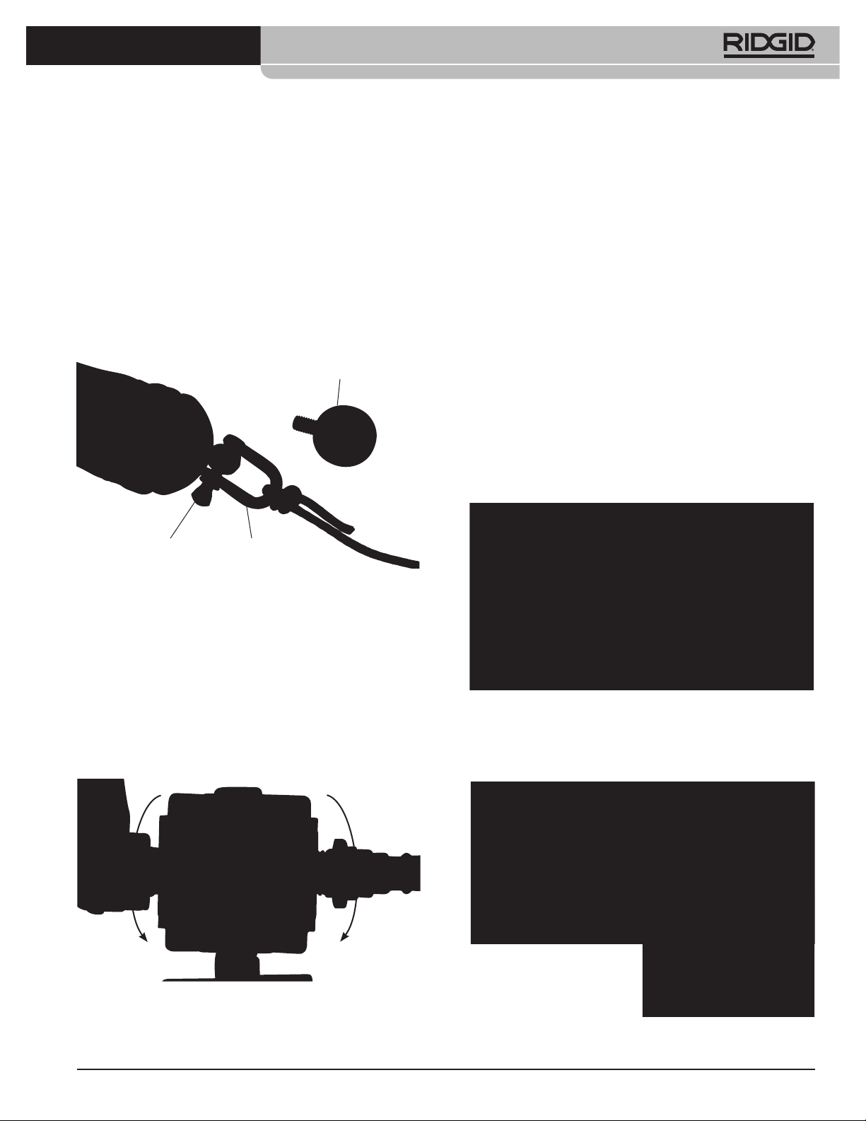
If using a pull rope on the front of the packer, the
packer ball will need to be unscrewed and the rope
attachment eye bolt screwed in place (See Figure
10). Rope can be attached directly to the eye bolt, or
the supplied D-ring or quick link. Securely attach the
pull ropes.
When using only pull ropes, attach the air hose to
the packer and lay the assembled packer and hose
next to the camera push cable. Mark the air hose at
the same distance as the mark on the camera push
cable (Similar to Figure 8). This will help properly
locate the patch in the pipe.
Packer Ball
Eye Bolt
D-Ring
7. Prepare the packer for the test insertion. Install packer
sleeve.
Installing Packer Sleeve
The packer sleeve protects the packer from the resin and
simplifies clean up.
1 Confirm that you have the correct packer, equipment
and materials for the patching work.
2. If needed, install containment on the packer (see
Containment section – Containment not used for test
insertion) .
3. Lay out the plastic table covering to protect your
selected work area from the resin and keep material
and equipment clean.
4. Make sure that the packer is clean. If needed, apply
baby powder to the rubber portion of the packer and
clean up any excess baby powder in the work area.
5. Insert the packer inside the provided clear packer
sleeve. See Figure 12.
Figure 10 – Removing Packer Ball/Installing Eye Bolt
6. Set up air supply and run an air hose to the point
of use. Attach the regulator to the air hose. Pull the
regulator adjustment knob out and turn clockwise to
confirm that there is adequate pressure (at least 100
psi) available to the regulator. Air pressure must be
available throughout the patching process to ensure
a complete patch. Pull the regulator adjustment
knob out and turn counterclockwise to reduce the air
pressure to zero. See Figure 11. Place regulator out
of way until ready to inflate the packer.
—
Figure 11 – Adjusting Regulator Pressure
Pull Knob To Adjust, Push Knob To Lock
+
Figure 12 – Inserting Packer Into Sleeve
6. The sleeve should extend approximately 1" past the
front of the packer and approximately 6" past back of
the packer (past the air connector), See Figure 13.
Approx. 6"
Back of the Packer
Figure 13 – Sleeve On
Packer (Proper
Overhangs)
Front of the Packer
999-995-411.10_REV A
Find Quality Products Online at: [email protected]
www.GlobalTestSupply.com
11
Page 14
Pipe Patch
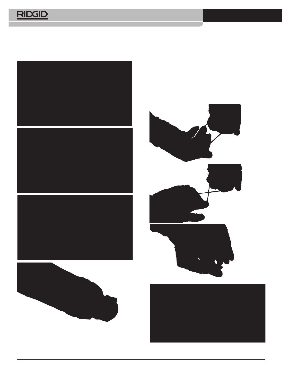
7. Place the packer in the middle of the width of the
sleeve. Fold the edges of the sleeve up and tight to
the packer. See Figure 14.
the packer, but do not cover the threaded connector.
Wrapping the tape down over the curve of the packer
end is important for proper retention of the sleeve in
place.
9. Secure the packer sleeve to the packer with provided
elastic bands doubled over every 12" Using the
correct elastic bands, doubling them over and
properly placing them is very important to the
function of the packer and patch. See Figure 15
and 16.
Figure 14 – Folding Sleeve Around Packer and Taping
8. Securely tape the packer sleeve at the front of the
packer (Figure 14). Wrap the tape around the metal
end of the packer, down over the curve of the end of
12
Find Quality Products Online at: [email protected]
www.GlobalTestSupply.com
Figure 15 – Doubling Over Elastic Bands
999-995-411.10_REV A
Page 15
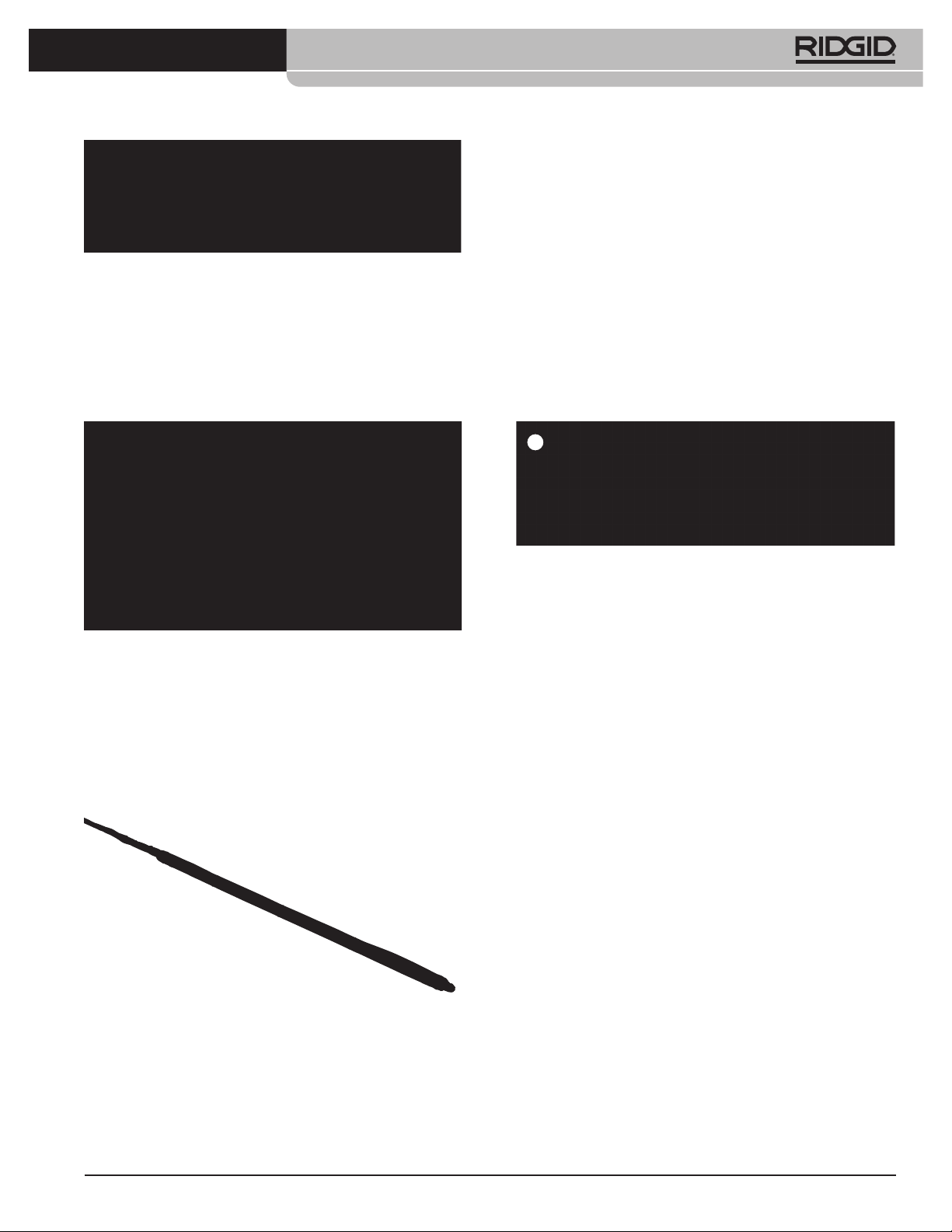
Figure 16 – Elastic Band Placement On Packer Sleeve
(Every 12")
10. Secure the sleeve at the back end of the packer
with tape, similar to the front. Wrap the tape around
the metal end of the packer, down over the curve of
the end of the packer. Wrapping the tape down over
the curve of the packer end is important for proper
retention of the sleeve in place. See Figure 17.
Pipe Patch
This increases the likelihood of a successful patch. Do
not attempt to install the patch without first doing a test
insertion. Consider the additional thickness that the containment/patch will add to the packer during patching and
whether that will prevent proper insertion of the patch. If
you cannot place the packer in the required time during
the test insertion, do not attempt to patch the pipe.
This is general guidance on packer insertion. Every jobsite is different and requires the skill and good judgment
of the installer to choose proper methods and practices.
For instance, a second access point on the other side of
the patch may be required. This allows an additional pull
rope to be fed through the pipe and attached to the front
of the packer to help pull the packer into place.
4
Figure 17 – Securing The Sleeve With Tape At The Back Of
The Packer
11. Roll the sleeve back to allow access to the air push
rod connection and pull rope tie off point. Securely
connect a single air push rod (or the air hose) and
tape the connection. Securely connect the pull rope
(see Figure 10). Roll the sleeve down the length of
the rod and rope and securely tape the end of the
sleeve. See Figure 18.
Figure 18 – Packer With Packer Sleeve Installed, Ready
For Use
Packer Test Insertion
The packer test insertion ensures that the packer and
equipment can navigate the pipe to the damaged section
in the required time and be retrieved without damage.
ENSURE PACKER CAN BE NAVIGATED TO THE PATCH LOCATION BY
PERFORMING A TEST INSERTION
1. Make sure that the correct packer is properly prepared, including the installation of a packer sleeve.
Containment is not typically needed for test insertion.
2. The packer sleeve can be lubricated with a small
amount of oil soap to simulate the lubricity of the
resin on the packer. The optional accessory ball and
spring guide can be used in place of the packer ball
for improved navigation.
3. Carefully insert the packer into the pipe system.
Monitor the amount of time it takes to insert the
packer.
4 Insert packer so that the distance mark on the air
push rod or air hose is near the same point at the
pipe entrance. Determine if it will be possible to
navigate the packer and the patch to the patch site
before the patch resin hardens. DO NOT INFLATE
packer during test insertion. Installing the patch is
time sensitive and if it is difficult or takes too much
time, it can cause the patching process to not work.
5 Reinspect the drain with camera. Confirm that the
packer is in the correct spot to apply the pipe patch.
6. Using the pull rope, retrieve the packer from the pipe
system. Do not pull on the air push rods, this can
damage the air push rods.
7. Remove the used packer sleeve from the packer.
Remove the air push rod or air hose assembly from
the packer.
999-995-411.10_REV A
Find Quality Products Online at: [email protected]
www.GlobalTestSupply.com
13
Page 16
Pipe Patch
Containment
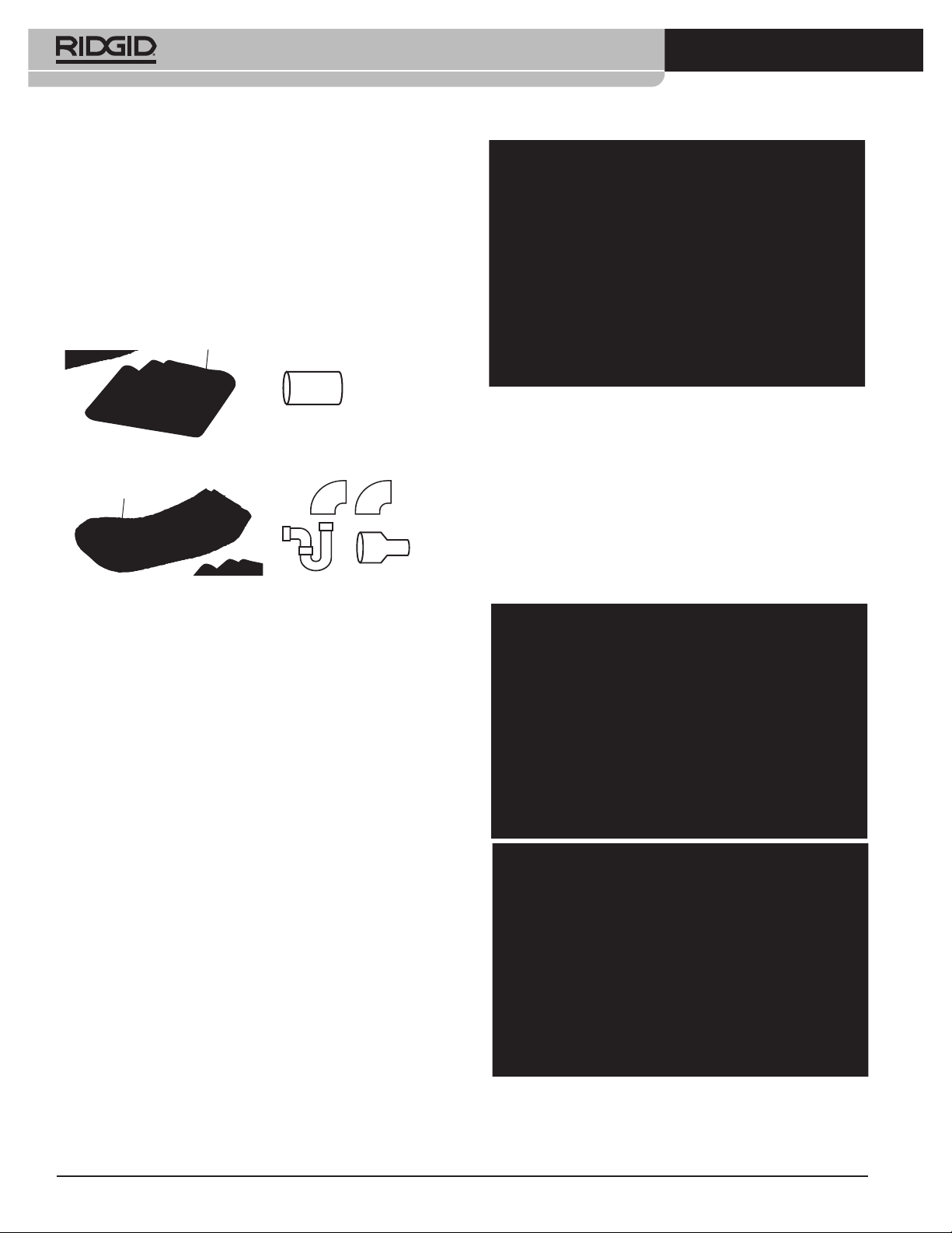
If the packer will be placed such that portions of the
packer will be unsupported (such as T’s or pipe damage
over 1" in diameter, connections, breaks, or the packer
extends into a larger size pipe or out of the drain) then
containment must be used. Additionally, if the pipe is
believed to be brittle (based on material, age, inspection
results, etc.), containment should always be used.
Containment can be done with a:
Containment Tube
• containment tube (for straight pipes)
Containment Liner
(Loop Stitch Material)
Figure 20 – Minimum Containment Tube Length
1. Using sharp scissors, cleanly and squarely cut the
containment tube to length. A clean, square cut will
minimize tearing when inflating.
2. Place the containment tube over the packer, lining it
up with the end of the packer.
• containment liner (loop stitch material) (for use in
bends).
Figure 19 – Containment Examples
Containment reduces the risk of the patch bulging into
the unsupported area and/or the packer being damaged
or bursting. Containment is always done under the packer
sleeve and will be removed with the packer after the
patch is complete. Because the packer diameter is larger
than it normally would be, a pull rope may be needed to
pull the packer into place. Containment tube and liner
can be reused, but if it is, it should be inspected to make
sure that it is in good shape and not damaged.
Containment Tube
The containment tube is used for straight pipes when
containment is needed. Containment tubes can be used
at one end, both ends or over the full packer.
For Ends Only
Determine the containment tube length. At a minimum,
the containment tube should be at least 12" (305 mm)
long and must extend at least 4" (100 mm) under the
patch. If applying a patch less than full length, the tube
can extend more than 4" under the end of the patch, but
no less. See Figure 20.
3. Place the packer in the middle of the width of the
tube. Fold the edges of the tube up and tight to the
packer. See Figure 21.
14
Find Quality Products Online at: [email protected]
www.GlobalTestSupply.com
999-995-411.10_REV A
Page 17
Pipe Patch
Figure 21 – Folding Containment Tube Around Packer
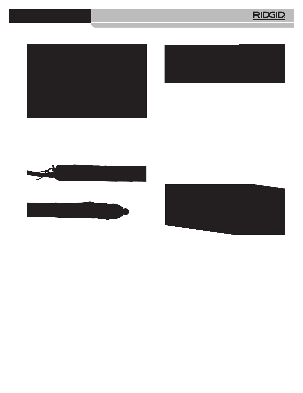
4. Securely tape the containment tube to the end of the
packer (Figure 22). Wrap the tape around the metal
end of the packer, down over the curve of the end of
the packer, but do not cover the threaded connector.
Back of the Packer
Front of the Packer
Figure 22 – Containment Tube Taped To End of Packer
(End Containment Only – Not For Complete
Packer)
Figure 23 – Cutting Containment Tube To Length For Full
Packer
2. Using sharp scissors, cleanly and squarely cut the
containment tube to length. A clean, square cut will
minimize tearing when inflating.
3. Place the containment tube over the packer, lining up
with the end of the front metal head of the packer.
4. Place the packer in the middle of the width of the
tube. Fold the edges of the tube up and tight to the
packer.
5. Securely tape the containment tube to the end of the
packer (Figure 24). Wrap the tape around the metal
end of the packer, down over the curve of the end of
the packer, but do not cover the threaded connector.
Figure 24 – Containment Tube Taped To End Of Packer,
Elastic Bands Every 12"
5. Use provided elastic bands doubled over individually
every 9"-12" to keep the containment tube neatly
folded and secured to the packer body.
6. Continue building out your packer as normal by
installing the packer sleeve.
For Full Packer
1. Measure the Containment tube to cover the entire
packer, including the hose and locking connector,
See Figure 23.
For the 2" Packer the locking connector does not
need to be covered. The length of the containment
tube should be the length of the 2" packer plus 4".
6. Use provided elastic bands doubled over individually
every 9"-12" to keep the containment tube neatly
folded and secured to the packer body.
7. Continue building out your packer as normal by installing the packer sleeve.
Containment Liner
Containment liner is required when patching through
bends to prevent wrinkles. Examples can be large holes
or corrosion in a bend. Using containment liner will increase the overall diameter of the packer making it tighter
in pipe but will not restrict the packer from navigating the
bends. Containment liner has loop stitch on the inside.
Containment liner cannot be used as a patch and patch
cannot be used as containment liner.
1. Measure the containment liner to cover the entire
packer end to end, including the metal ends of the
packer. See Figure 25.
999-995-411.10_REV A
Find Quality Products Online at: [email protected]
www.GlobalTestSupply.com
15
Page 18

Pipe Patch
Figure 25 – Measuring Containment Liner
2. Using sharp scissors, cleanly and squarely cut the
containment liner to length.
3. Slide the containment liner onto the packer. Baby
powder can be used on the packer to more easily
slide the liner over packer.
4. Tightly apply tape to the containment liner over the
metal ends of the packer as shown in Figure 26.
Tape should start where the black rubber of the
packer meets the metal head and continue over the
rounded end (but not cover the threaded connector).
The tightness of the tape over the rounded end holds
the containment liner in place. See Figure 26. Apply
doubled over elastic bands every 12". If needed, the
liner can be folded over.
1. Confirm that the packer is correctly prepared. Any
needed containment should be in place and the
packer sleeve installed.
2. Lay the patch next to the packer, centered along the
length. Confirm that there are equal lengths of black
rubber packer at either end of the patch – these are
the encroachment zones. Encroachment zones are
important to the proper installation of the patch. If the
patch is too close to the ends of the packer (in the
encroachment zone), the end of the patch will not be
held tightly to the pipe inside diameter and the patch
may not work. See the Specifications Table for the
minimum encroachment zone for each packer.
Encroachment Zone - The area at each end of the
packer that will not expand to the full to the pipe diameter when inflated. The patch CANNOT be in this
zone. If the patch is in this zone, the patch will not be
proper and may block the pipe. The encroachment
zone is measured from the point where the black
rubber meets the metal end of the packer. This zone
is 3" long for the 2" & 3" packers and 5" long for the
3"-4" & 4"-6" packers.
If containment is being used on the packer, the end
of the encroachment zone can be found by feeling for
the transition from the hard metal end of the packer
to rubber section.
Figure 26 – Packer With Liner, Ends Taped, Doubled Over
Elastic Bands Applied Every 12"
5. Continue building out your packer as normal by installing the packer sleeve. Pulling the patch onto the
packer with containment liner will be difficult.
Preparing The Patch
Always wear safety glasses and the provided protective
gloves when handling the resin. Prepare the patch and
resin only on the supplied table covering.
See resin containers and SDS for further information on
proper handling and use.
Once the resins are combined, the patching process
is time limited and must be completed within the
resin working time. If time runs out before the packer
is inflated in place, the patch must be disposed of
and the process restarted. Be sure all materials, equip-
ment and personnel are available and properly staged to
minimize the time it takes to get the patch prepared and
in place.
If the encroachment zones are less than specification,
then the patch should be carefully trimmed with sharp
scissors to allow at least the minimum encroachment
zone at either end of the packer.
Once patch length, position and encroachment zones
are confirmed, using a permanent marker, mark the
end locations of the patch on the packer sleeve. See
Figure 27.
Encroachment Zone
Figure 27A – Marking Encroachment Zone/Patch Ends
On Packer Sleeve
16
Find Quality Products Online at: [email protected]
www.GlobalTestSupply.com
999-995-411.10_REV A
Page 19

Patch End
Pipe Patch
28. Enough resin is supplied to fully saturate the
patch plus some. This excess resin can be left and
allowed to dry on the plastic table covering.
Figure 27B – Marking Encroachment Zone/Patch Ends
On Packer Sleeve
Wet Out Patch With Resin
Mixing Resin
3. Confirm that you have the correct patch resins – you
will always be mixing a set of two containers, one
marked “Part A” and one marked “Part B”. Both
containers should be marked for the same length
of the patch (32" or 3'). If making a 6' patch you will
need two sets of 3' containers. Confirm the use by
date is still good. Do not use out of date resin – this
can cause an improper patch.
4. Confirm that the patch resins are within the resin
application temperature. If they are outside of the
application temperature take appropriate steps to
bring them within temperature, such as placing the
unopened resin containers in cool or warm water
bath. If they are too warm, the resin will harden more
quickly, and if too cool, the resin will harden more
slowly.
5. Carefully open both resin containers. Pour all of Part
A into Part B. Securely replace the cap on resin and
vigorously shake the container for at least a minute to
thoroughly mix. Record the time that the resins were
poured together.
Figure 28 – Wetting Out The Patch Off The Packer
2. Carefully insert the packer into the patch (Figure 29).
Do not stretch or deform the patch. Position the patch
at the center of the packer assembly. Confirm that
the patch is centered and encroachment zones (as
marked earlier) are visible at each end. It is important
to have the patch centered on the packer to reduce
the risk of an improper patch. Confirm that the patch
is properly placed relative to any containment tube.
Wet Out Patch Off Packer
This is the generally recommended wet out method.
Wetting out the patch off the packer typically makes it easier to fully saturate the patch with the resin. This method
Figure 29 – Inserting The Packer In Patch
cannot be used for the 3"-4" packer.
1. With the patch in the middle of the table covering,
mix the resin and carefully open. Pour all the resin
mixture on the patch. Do not keep the mixed resin in
the container, it will start to heat up and may rupture
or melt the container.
3. Gather the excess patch together and fold over neatly
(see Figure 30). At the front end of the patch apply
a doubled over elastic band at the front edge of the
patch and every 1/2" past that until there are 4 elastic
bands in place. Continue to place doubled over
elastic band every 4" along the remaining length of
Using your gloved hands, thoroughly work the resin
into the patch. The patch should turn the yellow resin
color – there should be no white areas. See Figure
999-995-411.10_REV A
Find Quality Products Online at: [email protected]
www.GlobalTestSupply.com
the patch. Place another 4 elastic bands 1/2" apart at
the other end of the packer. See Figure 31. Doubling
over and proper placement of the elastic bands is
17
Page 20

Pipe Patchs
important to ensure that the patch stays in place
and does not move on the packer. Wipe excess
resin off the packer sleeve (not the patch).
Figure 30 – Gathering And Folding The Patch
4" Increments
1/2" Increments
patch. Confirm that the patch is properly placed relative to
any containment tube.
1. With the packer and patch in the middle of the table
covering, mix the resin and carefully open. Pour all
the resin mixture on the patch. Do not keep the mixed
resin in the container, it will start to heat up and may
rupture or melt the container.
Using your gloved hands, thoroughly work the resin
into the patch. See Figure 33. The patch should turn
the yellow resin color – there should be no white
areas. Enough resin is supplied to fully saturate the
patch plus some. This excess resin can be left and
allowed to dry on the plastic.
Figure 31 – Placement Of Doubled Over Elastic Band On
Patch
Figure 32 – Patch Properly Wet Out And Secured With
Doubled Over Elastic Bands
4. The Patch is ready to repair the pipe. Use the plastic
table covering around the patch to contain resin and
allow it to be carried to the pipe opening.
Wet Out Patch On Packer
This method is always used on the 3"-4" packers and
when using containment on the 3" packer. Prior to mixing
the resin, carefully insert the packer into the patch. Do
not stretch or deform the patch. Position the patch at the
center of the packer assembly. Confirm that the patch is
centered and encroachment zones (as marked earlier)
are visible at each end. It is important to have the patch
centered on the packer to reduce the risk of an improper
Figure 33 – Wetting Out The Patch On The Packer
2. Reconfirm that the patch is centered, encroachment
zone is visible at each end and that the patch is
properly placed relative to any containment devices.
3. Gather the excess patch together and fold over
neatly. At the front end of the patch apply a doubled
over elastic band at the front edge of the patch and
every 1/2" past that until there are 4 elastic bands in
place. Continue to place doubled over elastic bands
every 4" along the remaining length of the packer.
Place another 4 elastic band 1/2" apart at the other
end of the packer. See Figure 31. Doubling over
and proper placement of the elastic bands is
important to ensure that the patch stays in place
and does not move on the packer. Wipe excess
resin off the packer sleeve (not the patch).
4. The patch is ready to repair the pipe. Use the plastic
table covering around the patch to contain resin and
allow it to be carried to the pipe opening.
18
Find Quality Products Online at: [email protected]
www.GlobalTestSupply.com
999-995-411.10_REV A
Page 21
Pipe Patching
1. Change gloves.
2. If needed, attach the ball & spring leader guide to
the front of the packer. The leader guide will help the
packer negotiate bends and p-traps. Otherwise, if not
using a pull rope at the front of the packer, securely
install the packer ball.
3. Securely attach the remaining air push rods, pull
ropes and air hose assembly to the packer. Tape the
connections to reduce the risk of resin getting in the
fittings or the connection from coming loose.
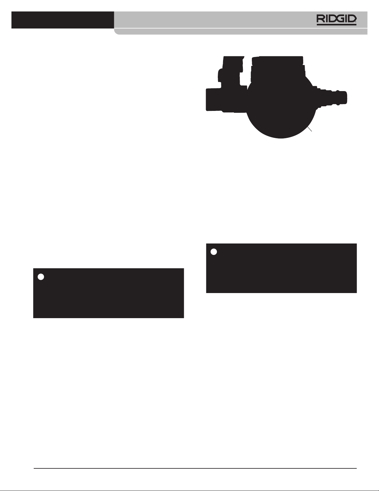
Pipe Patch
PSI
Figure 34 – Pressure Gauge
4. If needed, a small amount (up to 8 oz.) of an oil
type soap can be placed in the pipe to lubricate the
equipment as it is inserted.
5. Insert the packer assembly inside the pipe system.
Using the information learned from the test insertion,
work the patch into the place (see Figure 7-5). When
the insertion mark on the air push rod or air hose
aligns with the pipe entrance, inspect the patch position with the camera and confirm correct positioning.
Patch must be properly positioned prior to inflating
the packer. Confirm time since the resin was mixed.
Do not exceed the allowable working time. Wrapping
the camera inspection head spring with tape can help
to prevent resin from accumulating and drying in the
spring.
5
PREPARE THE PATCH AND POSITION THE PACKER IN
THE PROPER LOCATION
6. Attach the pressure regulator to the air push rod or air
hose.
7. Open the regulator valve. Pull the regulator knob and
slowly turn the regulator knob clockwise to inflate the
packer to the required air pressure (Figure 7-6). Refer
to the Specifications table for pressure values for
specific packer size. Note the time that the packer
was inflated. If you have exceeded the allowable
working time since the resin was mixed, the
packer/patch will need to be removed and you will
need to start with a new patch. See Figure 34.
Always use the pressure regulator on packer. Ex-
ceeding the maximum pressure, may result in the
packer rupturing. Incorrect inflation of packer could
result in the patch collapsing, or not opening up to the
full pipe diameter. This could also lead to the packer
becoming stuck in the pipe.
Once the packer is properly inflated, inspect the patch
position with the camera again to confirm correct.
Continue to monitor the air pressure to confirm that
it does not unexpectedly decrease. Do not shut the
regulator valve or change the air pressure.
6
INFLATE THE PACKER TO THE REQUIRED PRESSURE.
ALLOW THE RESIN TO CURE FOR THE RESIN SET TIME
Wipe up any spilled resin, allow to harden and dispose.
8. Allow the resin to cure for the appropriate amount
of time (“Set time”). Generally, the resin set time is
90 minutes. If the internal pipe temperature is below
50°F (10°C), set time is 180 minutes. If the pipe being
patched is outside of the resin application temperature
range, resin set time will be affected and further adjustments may need to be made. Lower temperatures
will increase set time and higher temperatures may
decrease set time. FULL CURE TAKES PLACE AT 4
HOURS under normal conditions.
Do not depressurize the packer before the set time is
complete. This could cause improper sealing, failure of
the patch, and blockage of the pipe.
9. Depressurize the system to loosen the packer assembly from the patch. See Figure 7-7.
999-995-411.10_REV A
Find Quality Products Online at: [email protected]
www.GlobalTestSupply.com
19
Page 22

Pipe Patch
7
ONCE RESIN IS CURED, DEPRESSURIZE THE PACKER
10. Remove the air hose connection and pressure regulator from the air push rod.
11. Using the pull rope, retrieve the packer assembly from
the pipe system. Do not pull the packer assembly with
the air push rods. The air push rods are designed for
pushing the packer into place and delivering air into
the packer. They are not designed to be used as the
primary method of extracting the packer and could
break if exposed to undue force.
12. Check the pipe patch with the camera. See Figure 7-8.
8
REMOVE THE PACKER
13. Remove the air push rod sections, pull rope and
leader guide from the packer.
14 Clean up the area. Allow excess resin to dry on table
covering and dispose.
Installing Multiple Patches
If the damaged area is longer than one patch, or if there
are multiple damaged areas, it is acceptable to install multiple patches. When installing multiple patches, generally
start with the patch that is the furthest down the line and
work back to the access point. Once the first patch has
reached its resin set time, the next patch can be started.
Patches can be overlapped as necessary - be aware of
the additional reduction in diameter from overlapping
patches.
Storage
WARNING
Disassemble the air push rod sections.
Make sure the equipment is clean. Wrap the air hose and
pull ropes. Store the packer and equipment in carry case,
or store straight and flat. Do not place anything on the
packer – this can damage the packer and cause leaks.
The equipment must be kept dry and indoors or well
covered if kept outdoors. Store the equipment in a locked
area that is out of reach of children and people unfamiliar
with pipe patching system. This equipment can cause
serious injury in the hands of untrained users.
Maintenance Instructions
WARNING
The pipe patching system must not be connected
to any air connection before any maintenance.
Always wear safety glasses and other appropriate
protective equipment when performing any maintenance.
Cleaning
After each use, clean the packer, air push rods and other
connections with a damp, soft cloth. A mild detergent or
antibacterial solution can be used if desired. Do not use
solvents, abrasives or other harsh cleaning agents. Do
not let anything into the air connections. Dirt, liquids, etc.
in the air system can damage the regulator and packer
and prevent proper operation.
Wipe off the dried resin using a paper towel.
Once the packer is clean, apply baby powder to the black
rubber portions of the packer. This will help protect the
rubber and allow sliding between the packer and the
packer coverings during use.
Check air connections/threads, clean as necessary.
Packer Testing
Test the packer to check for leaks and for proper inflation.
Do not test packer outside of properly sized pipe to avoid
equipment damage and burst hazard..
1. Install a packer sleeve on the packer.
2. Take a straight length of pipe matching the packer
diameter rating and at least one foot longer than the
packer. Make sure that pipe inside is clean and free
from debris.
3. Install a single air push rod to the packer. Insert the
packer inside the pipe, centering it in length.
4. Turn the regulator knob all the way counter-clockwise
to lower the pressure to zero. Close the regulator
valve. Attach the pressure regulator at the end of air
push rod. Attach the compressed air supply to the
pressure regulator.
5. Open the regulator valve. Slowly turn the regulator
knob clockwise to inflate the packer to the required
air pressure. Refer to the Specifications table for
pressure values for specific pipe size. Shut the
regulator valve.
20
Find Quality Products Online at: [email protected]
www.GlobalTestSupply.com
999-995-411.10_REV A
Page 23
Pipe Patch
6. Wait for 5 minutes and check the air pressure. If the
pressure has dropped, there is a leak, do not use the
packer until the leak is fixed. Leaks in the connections
may be able to be fixed by tightening connections or
lubricating seals. If the packer itself is leaking, it can
be sent for service.
7. After the test is complete, depressurize the system
and disassemble.
Service And Repair
WARNING
Improper service or repair can make machine
unsafe to operate.
Service and repair on the Pipe Patching system must be
performed by a RIDGID Authorized Independent Service
Center. Use only RIDGID service parts.
For information on your nearest RIDGID Authorized Independent Service Center or any service or repair questions, see Contact Information section in this manual.
Optional Equipment
Catalog
No.
74783 Pipe Patch Air Regulator
74798 Pipe Patch Ball & Spring Leader Guide for 3-4" & 4-6" Packers
74803 Pipe Patch 2" Ball Guide for 3-4" & 4-6" Packers
74808 Pipe Patch Flexible Adapter - 3-4" Packers
74813 Pipe Patch Flexible Adapter - 3" & 4-6" Packers
74818 Pipe Patch Standard to Lockable Air Adapter
74823 Pipe Patch Pull Rope - 250' Length
74828 Pipe Patch 100' Air Hose - Fittings Included
74838 Pipe Patch 1/4" Steinco F/F Lockable Coupling
74848 Pipe Patch “D” Ring for 3-4" & 4-6" Packers
74873 Pipe Patch Quick Links (Qty-2)
74863 Pipe Patch Resin Only - 3' Patch
74878 Pipe Patch Resin Only - 32" Patch
74858 Pipe Patch Elastic Bands for 3", 3-4" & 4-6" Packers
74853 Pipe Patch Carry Bag
74868 Pipe Patch Tape
75358 Pipe Patch Elastic Bands for 2" Packers
75368 Pipe Patch “D” Ring for 2" & 3" Packers
74883 Pipe Patch Air Gauge
74888 Pipe Patch Ball & Spring Leader Guide for 2" & 3" Packers
74893 Pipe Patch 2" Ball Guide for 2" & 3" Packers
Description
WARNING
To reduce the risk of serious injury, only use accessories specically designed and recommended for
use with the RIDGID Pipe Patching System, such as
those listed below.
Catalog
No.
74658 Pipe Patch Starter System - 2" Pipe x 32" Repair
74663 Pipe Patch Starter System - 3" Pipe x 32" Repair
74673 Pipe Patch Starter System - 3-4" Pipe x 3' Repair
74683 Pipe Patch Starter System - 4-6" Pipe x 3' Repair
74693 Pipe Patch Kit - 2" Pipe x 32" Repair
74698 Pipe Patch Kit - 3" Pipe x 32" Repair
74703 Pipe Patch Kit - 3-4" Pipe x 3' Repair
74708 Pipe Patch Kit - 3-4" Pipe x 6' Repair
74713 Pipe Patch Kit - 4-6" Pipe x 3' Repair
74718 Pipe Patch Kit - 4-6" Pipe x 6' Repair
74723 Pipe Patch Containment Kit for 2" Packer
74728 Pipe Patch Containment Kit for 3" Packer
74733 Pipe Patch Containment Kit for 3-4" Packer
74738 Pipe Patch Containment Kit for 4-6" Packer
74743 Pipe Patch Packer - 2" Pipe x 43" Length
74748 Pipe Patch Packer - 3" Pipe x 43" Length
74753 Pipe Patch Packer - 3-4" Pipe x 4' Length
74758 Pipe Patch Packer - 3-4" Pipe x 7' Length
74763 Pipe Patch Packer - 4-6" Pipe x 4' Length
74768 Pipe Patch Packer - 4-6" Pipe x 7' Length
74773 Pipe Patch Air Push Rod - 5' Length
Description
Disposal
Parts of this equipment contain valuable materials and
can be recycled. There are companies that specialize in
recycling that may be found locally. Dispose of the components in compliance with all applicable regulations.
Contact your local waste management authority for more
information.
999-995-411.10_REV A
Find Quality Products Online at: [email protected]
www.GlobalTestSupply.com
21
Page 24
Pipe Patch
Pipe Patching Checklist
Follow all instructions and warnings for the Pipe Patch System.
1. All materials and equipment are available, inspected and ready for use .......................................................................
2. Resin use by date is current and not expired .................................................................................................................
3. Patch location has been inspected and is appropriate ...................................................................................................
4. Patch location has been thoroughly cleaned and flushed .............................................................................................
5. Packer test insertion has been successfully completed .................................................................................................
6. Packer containment has been properly evaluated and applied as needed ...................................................................
7. Packer sleeve properly installed on packer ....................................................................................................................
8. Patch is properly prepared. Length, position & encroachment zones have been confirmed and patch end points have
been marked on packer sleeve ......................................................................................................................................
9. Resin temperature is within resin application temperature .............................................................................................
10. All of resin part A poured into resin part B container. Record time _______________. Shake vigorously for one minute.
Packer must be inflated and patch in place within 15 minutes of pouring resins together ............................................
11. Patch is properly wet out on/off packer ...........................................................................................................................
12. Patch is properly secured to packer with pipe patch rubber bands ...............................................................................
13. Patch/packer proper inserted to correct location and confirmed in proper location with camera ..................................
14. Packer inflated to proper pressure: Record time _______________. ..........................................................................
Packer Inflation Pressures
2" - 43psi (3 bar)
3" - 60psi (4.2 bar)
3" - 4" - 50psi (3.5 bar)
4" - 6" - 36psi (2.5 bar)
Packer must be inflated and patch in place within 15 minutes of pouring resins together. If you have exceeded the
allowable working time since the resin was mixed, the packer/patch will need to be removed and you will need to start
with a new patch.
15. Patch position re-inspected with the camera to confirm proper location .......................................................................
16. Resin has been allowed to set for an appropriate amount of time .................................................................................
Resin Set Time
90 Minutes (Internal Pipe Temperature 50°F to 68°F (10°C to 20°C))
180 Minutes (Internal Pipe Temperature 41°F to 49°F (5°C to 9°C))
17. Depressurize and remove packer. Record time _______________. ............................................................................
999-995-411.10_REV A
Find Quality Products Online at: [email protected]
www.GlobalTestSupply.com
23
 Loading...