

Page 1

K9-102 & K9-204 Manual
Model K9-102 & K9-204
™
FlexShaft
Drain Cleaning
Machines
Find Quality Products Online at: [email protected]
www.GlobalTestSupply.com
Page 2

FlexShaft™ Drain Cleaning Machines
999-995-158.08_REV. C
Table of Contents
Safety Symbols .................................................................................................................... 2
General Safety Rules
Work Area Safety .............................................................................................................. 2
Electrical Safety ................................................................................................................ 2
Personal Safety ................................................................................................................. 2
Tool Use and Care ............................................................................................................ 3
Service .............................................................................................................................. 3
Specific Safety Information ...............................................................................................3
FlexShaft Drain Cleaning Machine Safety ........................................................................ 3
Description ........................................................................................................................... 4
Specifications ...................................................................................................................... 5
Specifications - Acceptable Battery Powered Drills .......................................................... 5
Standard Equipment ......................................................................................................... 5
Pre-Operation Inspection .................................................................................................... 5
Machine and Work Area Set-up .......................................................................................... 6
Battery Powered Drill Set-up and Operation ..................................................................... 7
Drill Switch ........................................................................................................................ 7
Drill Speed ........................................................................................................................ 8
Drill Adjustment Clutch Setting ......................................................................................... 8
Installing/Adjusting Chain Knocker ................................................................................... 9
Operating Instructions .......................................................................................................11
Draining the Drum .......................................................................................................... 15
Transportation ................................................................................................................. 15
Storage ............................................................................................................................... 15
Maintenance Instructions ................................................................................................. 15
Cleaning ......................................................................................................................... 15
Lubrication ....................................................................................................................... 15
Cable Assembly Replacement ......................................................................................... 15
Troubleshooting .............................................................................................................. 15
Service And Repair ......................................................................................................... 16
Optional Equipment .......................................................................................................... 16
Disposal .............................................................................................................................. 17
EC Declaration of Conformity .................................................................. Inside Back Cover
Lifetime Warranty ................................................................................................. Back Cover
*Original Instructions - English
ii
Find Quality Products Online at: [email protected]
www.GlobalTestSupply.com
Page 3

FlexShaft™ Drain Cleaning Machines
999-995-158.08_REV. C
Safety Symbols
In this operator’s manual and on the product, safety symbols and signal words are used to
communicate important safety information. This section is provided to improve understanding of these signal words and symbols.
This is the safety alert symbol. It is used to alert you to potential personal injury hazards. Obey
all safety messages that follow this symbol to avoid possible injury or death.
DANGER
WARNING
CAUTION
NOTICE
portant information on the safe and proper operation of the equipment.
DANGER indicates a hazardous situation which, if not avoided, will result in death
or serious injury.
WARNING indicates a hazardous situation which, if not avoided, could result in death
or serious injury.
CAUTION indicates a hazardous situation which, if not avoided, could result in minor
or moderate injury.
NOTICE indicates information that relates to the protection of property.
This symbol means read the operator’s
manual carefully before using the equipment. The operator’s manual contains im-
This symbol means always wear safety
glasses with side shields or goggles while
using this equipment to reduce the risk of
eye injury.
This symbol indicates the risk of hands,
fingers or other body parts being caught,
wrapped or crushed in the drain cleaning
FlexShaft.
This symbol indicates the risk of the electrical shock.
This symbol indicates the risk of fingers or
other body parts being caught, wrapped,
crushed or struck by the chain knocker.
Do not operate tool with the cable end outside
of the drain.
This symbol means always wear gloves
when handling or using this equipment to
reduce the risk of infections, burns or other
serious personal injury from the drain contents.
General Safety Rules
WARNING
Read and understand all warnings and
instructions. Failure to follow all warnings and instructions may result in electric shock, fire, and/or serious injury.
SAVE THESE INSTRUCTIONS!
Work Area Safety
• Keep work area clean and well lit. Clut-
tered or dark areas invite accidents.
• Do not operate tools in explosive at-
mospheres, such as in the presence of
flammable liquids, gases, or dust. Tools
create sparks which may ignite the dust or
fumes.
• Keep children and b
while operating tools. Distractions can
cause you to lose control.
• Keep floors dry and free of slippery
materials such as oil. Slippery floors
invite accidents.
2
y-standers away
Electrical Safety
• Avoid body contact with earthed or
grounded surfaces such as pipes, radiators, ranges and refrigerators. There is
an increased risk of electrical shock if your
body is earthed or grounded.
• Do not expose power t
ools to rain or
wet conditions. Water entering a power
tool will increase the risk of electrical
shock.
• If operating a power t
ool in a damp
location is unavoidable, use a ground
fault circuit interrupter (GFCI) protected
supply. Use of a GFCI reduces the risk of
electric shock.
Personal Safety
• Stay alert, watch what you are doing
and use common sense when operating tools. Do not use tools while
you are tired or under the influence of
drugs, alcohol, or medication. A mo-
ment of inattention while operating t
may result in serious personal injury.
• Use personal protectiv
e equipment.
ools
Find Quality Products Online at: [email protected]
www.GlobalTestSupply.com
Page 4

FlexShaft™ Drain Cleaning Machines
999-995-158.08_REV. C
Always wear eye protection. Protective
equipment such as dust mask, non-skid
safety shoes, hard hat, or hearing protection used for appropriate conditions will
reduce personal injuries.
• Do n
ot overreach. Keep proper footing
and balance at all times. Proper footing
and balance enables better control of the
tool in unexpected situations.
Tool Use and Care
• Do not force tool. Use the correct tool
for your application. The correct tool will
do the job better and safer at the rate for
which it is designed.
• Store idle tools out of the reach of chil-
dren and do not allow persons unfamiliar with the tool or these instructions to
operate the tool. Tools can be dangerous
in the hands of untrained users.
• Maintain tools. Check f
or binding of moving parts, breakage
of parts and any other condition that
may affect the tool’s op er ation. If damaged, have the tool repaired before use.
Many accidents are caused by poorly
maintained tools.
• Keep handles dry, clean and free from
oil and grease. Allows for better control
of the tool.
or misalignment
Service
• Have your tool serviced by a qualified
repair person using only identical replacement parts. This will ensure that
the safety of the tool is maintained.
Specific Safety
Information
WARNING
This section contains important safety
information that is specific to this tool.
Read these precautions carefully before using the FlexShaft™ Drain Cleaning
Machine to reduce the risk of electrical
shock or other serious injury.
SAVE ALL WARNINGS
AND INSTRUCTIONS FOR
FUTURE REFERENCE!
Keep this manual with machine for use by
the operator.
FlexShaft Drain Cleaning
Machine Safety
• Always use safety glasses and gloves
in good condition while handling or
using. Use latex or rubber gloves, face
shields, protective clothing, respirators or
other appropriate protective equipment
when chemicals, bacteria or other toxic
or infectious substances are suspected to
be present to reduce the risk of infections,
burns or other serious personal injury.
• Do not use with
ting with a corded drill increases the risk
of electrical shock and other injuries.
• Do not allow the chain knocker/end of
cable to stop turning while drill switch
is depressed. This can over-stress the
cable and may cause twisting, kinking or
breaking of the cable assembly and may
result in serious personal injury.
• Practice good hygiene. Do not eat or
smoke while handling or operating the
tool. After handling or operating drain
cleaning equipment, use hot, soapy
water to wash hands and other body
parts exposed to drain contents. This
will help reduce the risk of health hazards
due to exposure to toxic or infectious
material.
• Only use the FlexShaft Dr
ing Machine for the recommended
drain sizes. Using the wrong size drain
cleaner can lead to twisting, kinking or
breaking of the cable and may result in
personal injury.
• Keep hand on the cable assembl
whenever the FlexShaft Machine is running. This provides better control of the
cable and helps prevent twisting, kinking
and breaking of the cable and reduces the
risk of injury.
• Position machine cable outlet within
3' (1 m) of the drain inlet or properly
support exposed cable assembly when
the distance exceeds 3' (1 m). Greater
distances can cause control problems leading to twisting, kinking or breaking of the
cable. Twisting, kinking or breaking cable
may cause striking or crushing injuries.
• One person must control both the
cable assembly and cordless drill. Do
not lock drill switch in the ON position
during operation. If the cable stops rotating, the operator must be able to release
the drill switch to prevent twisting, kinking
a corded drill. Opera-
ain Clean-
y
3
Find Quality Products Online at: [email protected]
www.GlobalTestSupply.com
Page 5

FlexShaft™ Drain Cleaning Machines
999-995-158.08_REV. C
and breaking of the cable and reduce the
risk of injury.
• Do not wear loose clothing or jewelry.
Keep your hair and clothing away from
moving parts. Loose clothing, jewelry or
hair can be caught in moving parts.
• Do not operate this machine if oper-
ator or machine is standing in water.
Operating machine while in water increases the risk of electrical shock.
• Do not use if there is the risk of con-
tact with other utilities (such as natural
gas or electric) during operation. Visual
inspection of the drain with a camera is
a good practice. Crossbores, improperly
placed utilities and damaged drains could
allow the cutter to contact and damage the
utility. This could cause electrical shock,
gas leaks, fire, explosion or other serious
damage or injury.
• Read and understand these instruc-
tions, the battery drill instructions and
the instructions for any other equipment used with this tool before operating. Failure to follow all instructions may
result in property damage and/or serious
injury.
for use on roots and cleaning the pipe wall of
scale. Plain chain knockers are for general use,
including grease. FlexShaft Drain Cleaners
are well suited to use with inspection cameras
during the drain cleaning process.
The FlexShaft Machines are lightweight and
compact for ease of transport.
Carry Handle
Chain
Drain
Hole
Drill
Shaft
Warning
&
Operation
Label
Figure 1A – RIDGID® FlexShaft Drain Cleaning
Machine
Knocker
Cable/
Knocker
Hook
Cable
Assembly
Cable
Bushing
Feet
Foot
(Horizontal-
Use Position)
Figure 1B – RIDGID® FlexShaft Drain Cleaning
Machine
Description
The RIDGID® Model K9-102 and K9-204
FlexShaft™ Drain Cleaning Machines are designed to clean and descale pipes and drain
lines as called out in the Specifications.
A user supplied battery powered drill is used to
drive the FlexShaft Drain Cleaning Machines.
The FlexShaft Drain Cleaning Machine cable
assembly is manually fed in and out of the
drain. A chain knocker that expands to the
pipe inside diameter is used to break up the
blockage and clean the walls of the pipe. Chain
knockers with carbide cutting tips are available
4
Find Quality Products Online at: [email protected]
www.GlobalTestSupply.com
Figure 1C – Cable End/Chain Knocker
Cable
Hook
Chain
Knocker
Cable
Bushing
Page 6

FlexShaft™ Drain Cleaning Machines
999-995-158.08_REV. C
Specifications
Model ..........................................................K9-102 K9-204
Drain Capacity (Nom.)
Cable Diameter (without Sheath)................
Cable Assy. Diameter (with Sheath)
Cable Assembly Length ..............................50' (15.2 m) 70' (21.3 m)
Rotational Speed
Drill Attachment
Weight (without Drill/Knocker)
Dimension (without Drill)
Operating temperature................................20°F to 140°F (-6°C to 60°C)
................................1
........................................Maximum 2500 RPM Maximum 2500 RPM
..........................................
.................. 24.3 lbs. (11.0 kg) 37.3 lbs. (16.9 kg)
...........................19.2" × 7.5" × 22.1" 21.1" x 10.8" x 24.2"
1
/4" to 2" (32 – 50 mm) 2" to 4" (50 – 100 mm)
1
/4" (6 mm)
3
...........
/8" (9.5 mm)
5
/16" Hex (8 mm)
(488 mm × 191 mm × 562 mm) (536 mm x 274 mm x 615 mm)
5
/16" (8mm)
1
/2" (12.7 mm)
5
/16" Hex (8 mm)
20°F to 140°F (-6°C to 60°C)
It is not recommended to clean glass, ceramic,
porcelain or similar fixtures with the FlexShaft
Drain Cleaners as it may damage the fixture.
Specifications - Acceptable
Battery Powered Drills
Rotational Speed .... 1800 to 2500 RPM
Chuck Size
Clutch
Switch Type.............
............. 3/8" or greater
..................... With adjustable torque
Momentary C
ontact
Switch Lock ............ Not equipped with
Drill must carry appropriate certification mark
for the market (CE mark, c()us mark, etc.)
Do not use corded drills, hammer drills or
impact drivers. Use of an inappropriate drill
increases the risk of equipment damage and
personal injury. See Battery Powered Drill
Set-up and Operation section.
Standard Equipment
Refer to the RIDGID catalog for details on equipment supplied with specific drain cleaning
machine catalog numbers.
NOTICE
drains. If properly used it will not damage a
drain that is in good condition and properly
designed, constructed and maintained. If the
drain is in poor condition, or has not been
properly designed, constructed and maintained, the drain cleaning process may not be
effective or could cause damage to the drain.
The best way to determine the condition of
a drain before cleaning is through visual inspection with a camera. Improper use of this
drain cleaning machine can damage the drain
cleaning machine and the drain. This machine
may not clear all blockages.
This machine is made to clean
Pre-Operation Inspection
WARNING
Before each use, inspect your Drain
Cleaning Machine and correct any problems to reduce the risk of serious injury
from electric shock, twisted or broken
cables, chemical burns, infections and
other causes and prevent Drain Cleaning
Machine damage.
Always wear safety glasses, and other
appropriate protective equipment when
inspecting your Drain Cleaning Machine.
1. Clean the machine, including handles
and controls. This aids inspection and
helps prevent the machine or control
from slipping from your grip. Clean and
maintain the machine per the maintenance instructions.
2. Inspect the machine for:
• Proper assembly and complet
• Any broken, worn, missing, misaligned
or binding parts.
• Presence and readability of the warning
label (see Figure 2).
Max. 75%
Figure 2 – Warning Label
eness.
1800-2500
/min
5
Find Quality Products Online at: [email protected]
www.GlobalTestSupply.com
Page 7
FlexShaft™ Drain Cleaning Machines
999-995-158.08_REV. C
• Smooth and free movement of the cable assembly in and out of the machine.
• Any condition which may prevent safe
and normal operation.
If any problems are found, do not use the
drain cleaning machine until the problems have been repaired.
3. Clean any debris from the cable assem
bly and chain knockers. Inspect sheath
for wear and damage. There should not
be any cuts, kinks, breaks or excessive
wear. Inspect the cable near the chain
knocker. Cable assemblies should not be
bent or deformed. Cable strands should
be tight to one another without separation. Inspect chain knocker for damaged
or lost carbide cutting tips (if equipped)
and wear of the chain itself. If chain links
are worn more than ¼ through or damaged, replace the chain knocker. Replace
worn and damaged equipment before
using drain cleaning machine.
Confirm that the chain knocker is prop-
erly set up and is secure on the cable.
4. Inspect the battery powered drill per its
instructions. Make sure that the drill is in
good operating condition and the switch
controls the drill operation. Confirm that
the drill meets the requirements in the
Specification section and is properly set
for use with the machine.
5. Inspect and maintain any other equipment being used per its instructions t
make sure it is functioning properly.
1. Check for an appropriate work area.
Operate in a clear level, stable, dry location. Do not use the Drain Cleaning
Machine while standing in water.
2. Inspect the drain to be cleaned. If possible, determine the access point(s) to the
drain, the size(s), length(s), and material(s) of the drain, distance to mainlines,
the nature of the blockage, presence of
drain cleaning chemicals or other chemicals, etc.
If chemicals are present in the drain, it
is import
ant to understand the specific
safety measures required to work around
those chemicals. Contact the chemical
manufacturer for required information.
Confirm no other utilities are present in
the drain or area to reduce the risk of
damage. Visual inspection of the drain
with a camera is a good practice.
If needed, remove fixture (water closet,
etc.) to allow access to drain. Do not run
the chain knocker in a fixture. This could
damage the FlexShaft Machine or the
fixture.
Best drain cleaning results will occur if
er is flowing during the drain cleaning
wat
process to wash away debris. For 1
1
/2” sink drains, cut away wall pipes
and 1
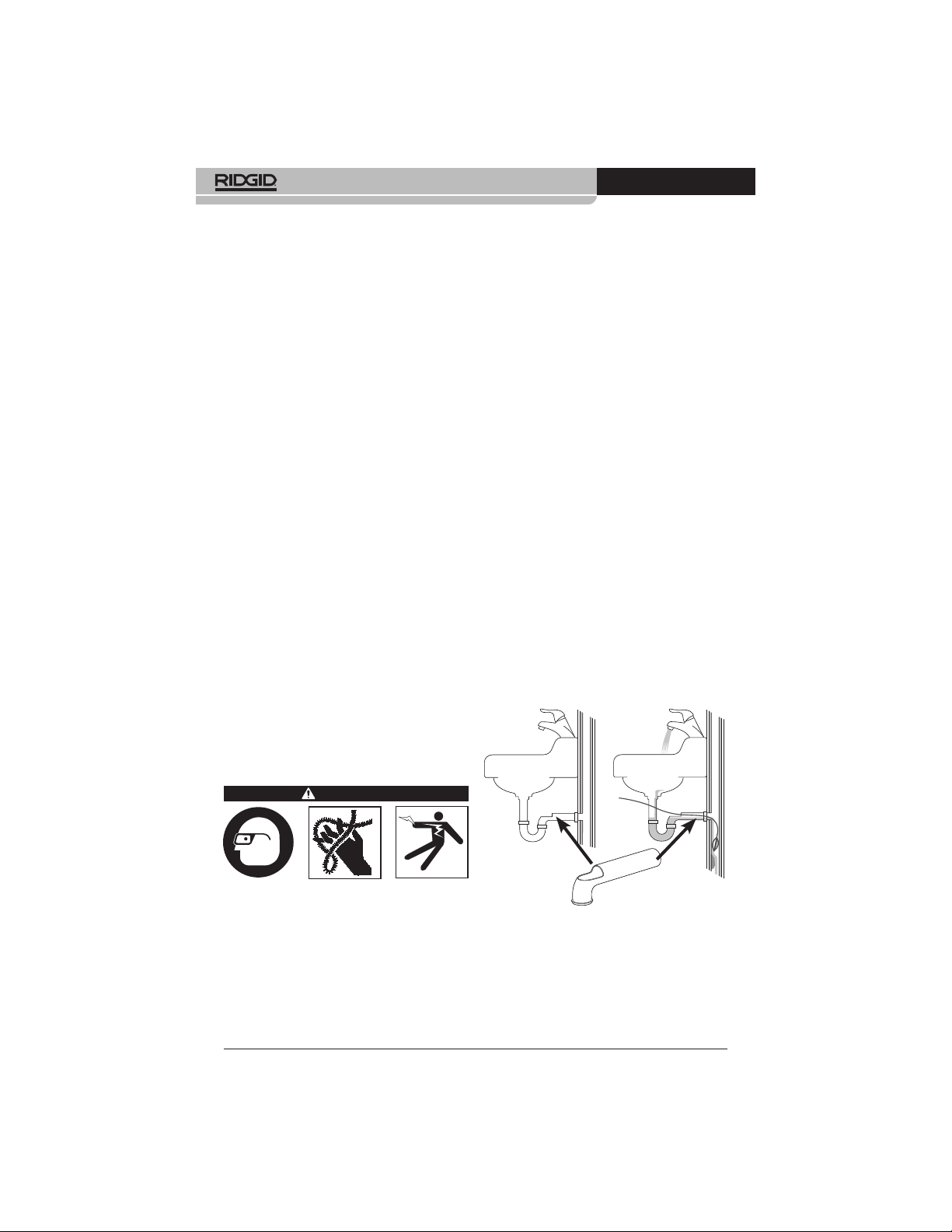
are available to allow this. See Figure 3
for installation. Place a container to catch
any drain contents that may spill.
o
1
/4”
Machine and Work Area
Set-up
WARNING
Set up the Drain Cleaning Machine and
work area according to these procedures to reduce the risk of injury from
electric shock, fire, machine tipping,
twisted or broken cables, chemical
burns, infections and other causes, and
prevent machine damage.
Always wear safety glasses and other
appropriate protective equipment when
setting up your Drain Cleaning Machine.
6
Figure 3 – Wall Pipe Installation
3. Determine the correct equipment for the
applic
ation. See Specifications.
4. Make sure all equipment has been properly inspected.
Find Quality Products Online at: [email protected]
www.GlobalTestSupply.com
Page 8
FlexShaft™ Drain Cleaning Machines
999-995-158.08_REV. C
5. If needed, place protective covers in the
work area. The drain cleaning process
can be messy.
6. Place the Drain Cleaning Machine on
the ground with the dr
Machine should sit squarely and firmly
on the ground. Do not operate with the
drill shaft horizontal. This will reduce the
risk of tipping.
7. Remo
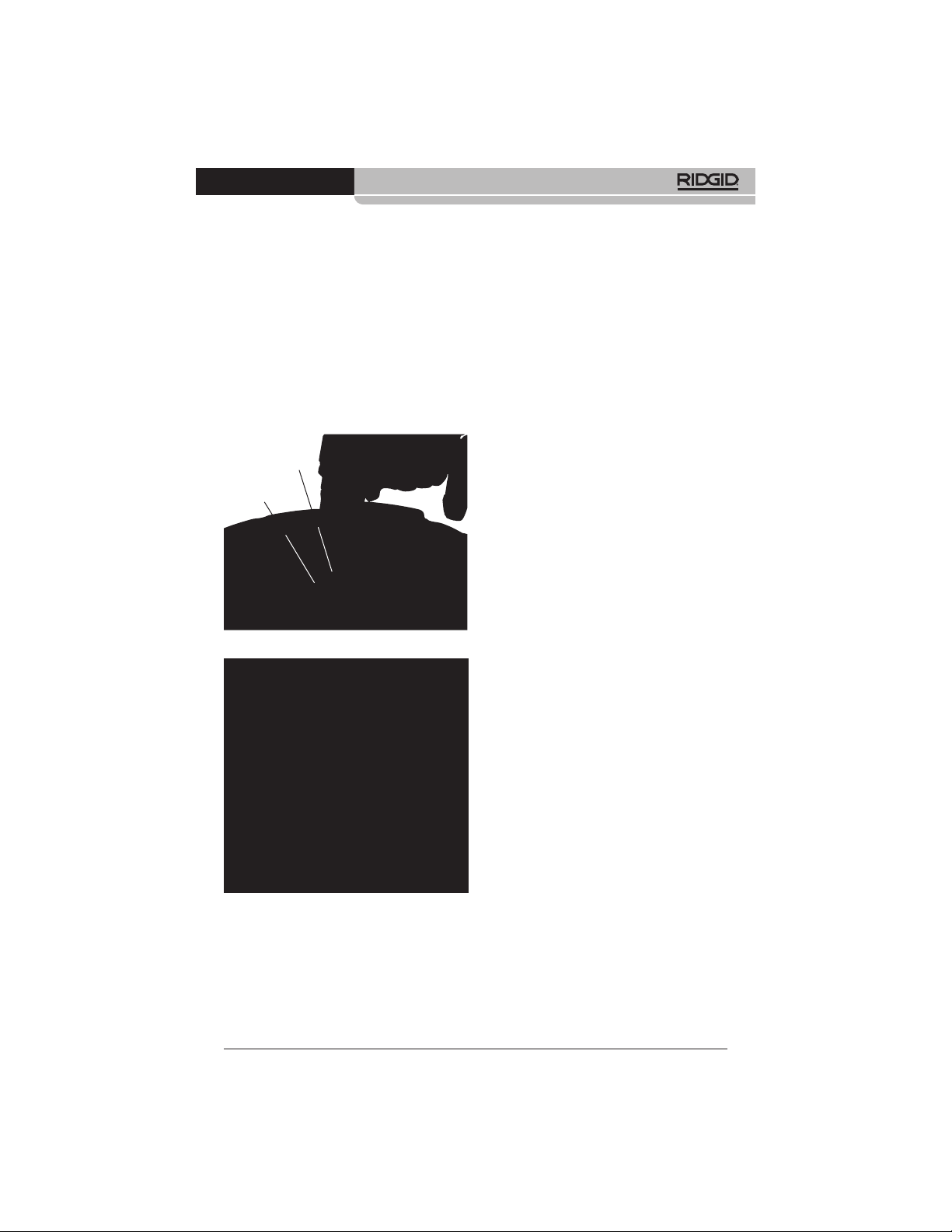
Figure 4 – Attaching Drill To Drill Shaft
ve the battery from the drill. Properly
set-up the drill. (See Battery Powered
Drill Set-up and Operation section.) Securely attach the drill chuck to the hex of
the drill shaft (Figure 4).
Drill
Shaft
FOR
Arrow
ill shaft vertical.
drain access, extend the drain access
with similar sized pipe and fittings (see
Figure 5). Improper cable assembly support can allow the cable to kink and twist
and can damage the cable or injure the
operator. Extending the drain back to the
Drain Cleaning Machine also makes it
easier to feed cable assembly into drain.
9. Disconnect the chain knocker from the
hook and pull approximately 4’ (1.2 m) of
cable assembly out of the machine.
10. Mark the sheath to indicate when the
chain knocker is approaching the drain
opening when withdrawn. This can be
done with tape. This reduces the risk of
the chain knockers coming out of the
drain and whipping around. The distance
depends on the configuration of the drain,
but should be at least 4’ (1.2 m) from the
chain knocker.
11. Ensure chain knocker is properly installed
(see Installing/Adjusting Chain Knocker).
12. Insert chain knocker end at least 1’ (0.3 m)
into drain.
13. Evaluate the work area and determine if
any barriers are needed to keep bystanders away from the drain cleaning machine and work area. The drain cleaning
process can be messy, and bystanders
can distract the operator.
14. Position the machine for easy accessibility. You must be able to hold and control
the cable assembly and the drill switch.
15. With dry hands, inser
the drill.
t the battery into
Battery Powered Drill
Set-Up and Operation
See the Specifications section along with this
section for information on acceptable battery
powered drills for use with the FlexShaft Drain
Cleaning Machines. There are many types of
battery powered drills available, and not all are
appropriate for use with the FlexShaft Drain
Figure 5 – Example of Extending Drain Access
8. Position the Drain Cleaning Machine so
Find Quality Products Online at: [email protected]
to within 3’ of Machine Cable Outlet
that the cable outlet is within 3’ (1 m) of
the drain access. Greater distances from
the drain access increases the risk of
the cable assembly twisting or kinking. If
the FlexShaft Machine cannot be placed
with the cable outlet within 3’ (1 m) of the
www.GlobalTestSupply.com
Cleaning Machines. If there is any question
about appropriateness of a drill for this application, do not use it. Remove the battery from
the drill before making any adjustments or
attaching to/removing from the drain cleaning
machine.
Drill Switch
The drill must be equipped with a momentary contact switch without a switch lock. This
7
Page 9
FlexShaft™ Drain Cleaning Machines
999-995-158.08_REV. C
means that the drill will only turn when the
operator is depressing the drill switch. If the drill
switch is released, the drill will turn OFF. Set
drill in “FOR” rotation (see Figure 4).
Drill Speed
When using your FlexShaft Drain Cleaning
Machine, the required rotational speed range
is 1800 – 2500 rpm. Cleaning will be optimized
by rotating the chain knockers closer to the
2500 rpm maximum. To do this, know your battery powered drill specifications and settings to
optimize operation. Many battery powered drills
have multiple speed settings, and typically the
highest speed is in the range for operation of
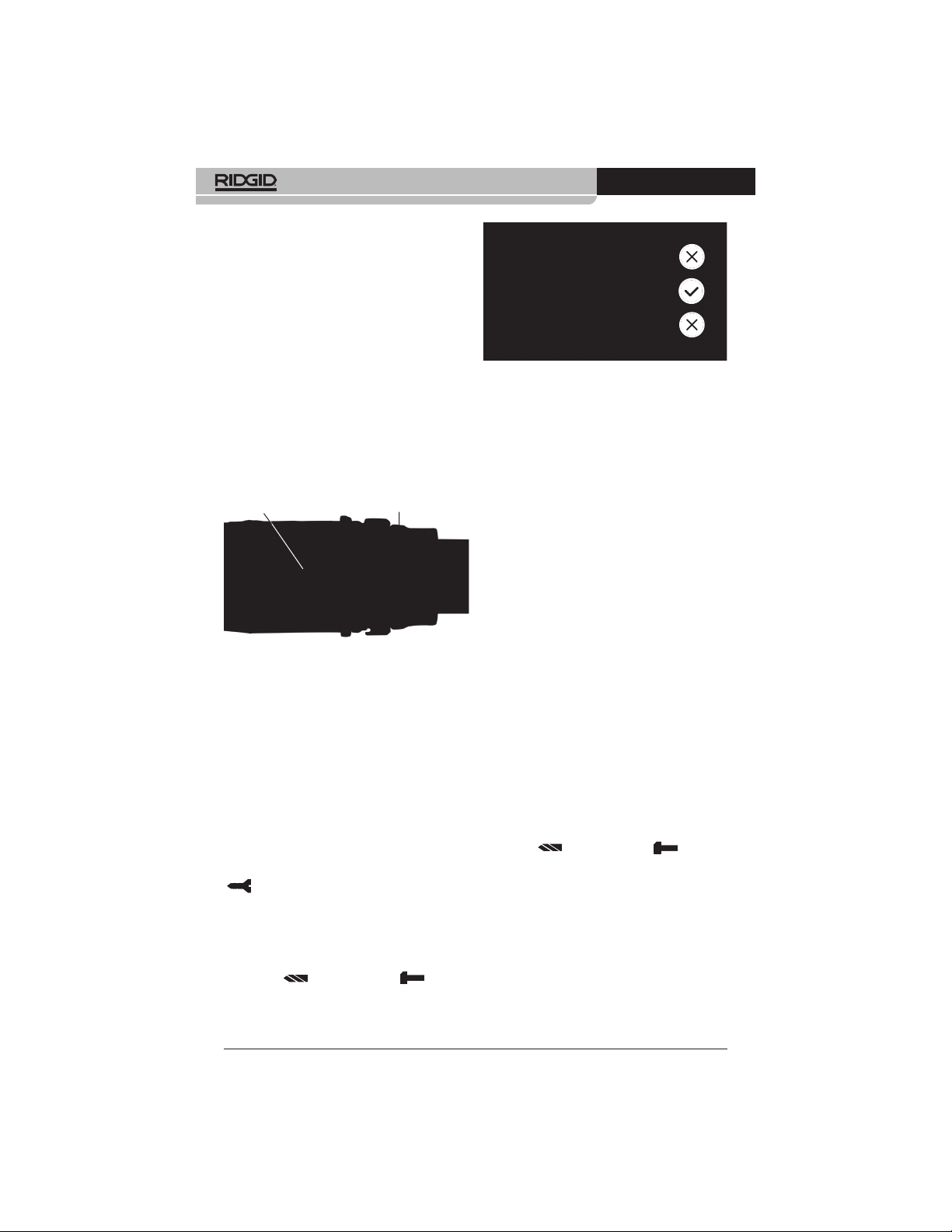
the FlexShaft equipment. See Figure 6 for an
example of drill speed settings. Do not operate
the FlexShaft drain cleaning machine at over
2500 rpm.
Drill Speed Settings Torque Adjustment Collar
Figure 6 – Drill Settings
Drill Adjustable Clutch Setting
Always use a battery powered drill equipped
with a properly set adjustable clutch. This will
help reduce the risk of cable damage in the
drum of the drain cleaner and reduce handle
forces.
Battery powered drills equipped with adjustable
clutches will typically have a torque adjustment
collar (Figure 6) marked with a scale in num-
bers starting at one and increasing to indicate
increasing torque at clutch disengagement.
The adjustable clutch is many times used for
driving screws, and may have a selector that
needs to be set to the “Screw Driving Mode”
( ) for the adjustable clutch to work. When
the adjustable clutch releases, the motor continues to turn but the drill chuck does not. Many
times this is accompanied by vibration/noise
from the drill.
Battery powered drills are often also equipped
with “Drill” ( ) and “Hammer” ( ) modes
of operation (Figure 7). In these modes, the
adjustable clutch does not work, and these
modes should never be used for FlexShaft
Drain Cleaning Machine operation.
Figure 7 – Selecting Proper Mode
When using the FlexShaft Drain Cleaning
Machines, always start with the adjustable
clutch set to approximately 25% of the total
clutch adjustment range (example – if the
torque adjustment collar on the drill is marked
from 1 to 20, the initial setting should be 5).
Operate the drain cleaner per these instructions. When clearing blockages, operate drill
at full speed for best cleaning. Do not force
the chain knocker into the blockage – if the
chain knocker cannot turn, it cannot clean
the drain. The chain knocker may need to be
moved away from the blockage to come back
up to speed. If during operation the drill clutch
continuously releases (“clutches out”), release
the drill switch and withdraw the cable from the
drain. Review the drain cleaner set up and operation and confirm everything is correct – an
important part of the set up for proper operation is chain knocker selection (See Figure 9
for details) and adjustment. Make any needed
changes and continue cleaning drain.
If the drill clutch continues to release during
operation, the drill adjustable clutch setting
can be increased. The drill clutch can be increased in steps up to 75% of the total clutch
adjustment range. (example – if the torque
adjustment collar on the drill is marked from 1
to 20, the maximum setting should be no more
than 15). Do not exceed 75% of the total
clutch adjustment range. Never place drill
in “Drill” ( ) or “Hammer” ( ) mode –
this disables the adjustable clutch. This
increases the risk of cable damage in the
drum of the drain cleaner.
If the drill clutch continues to release when set
at 75% of the total clutch adjustment range,
consider using another RIDGID drain cleaning
machine.
8
Find Quality Products Online at: [email protected]
www.GlobalTestSupply.com
Page 10
FlexShaft™ Drain Cleaning Machines
999-995-158.08_REV. C
Installing/Adjusting Chain
Knocker
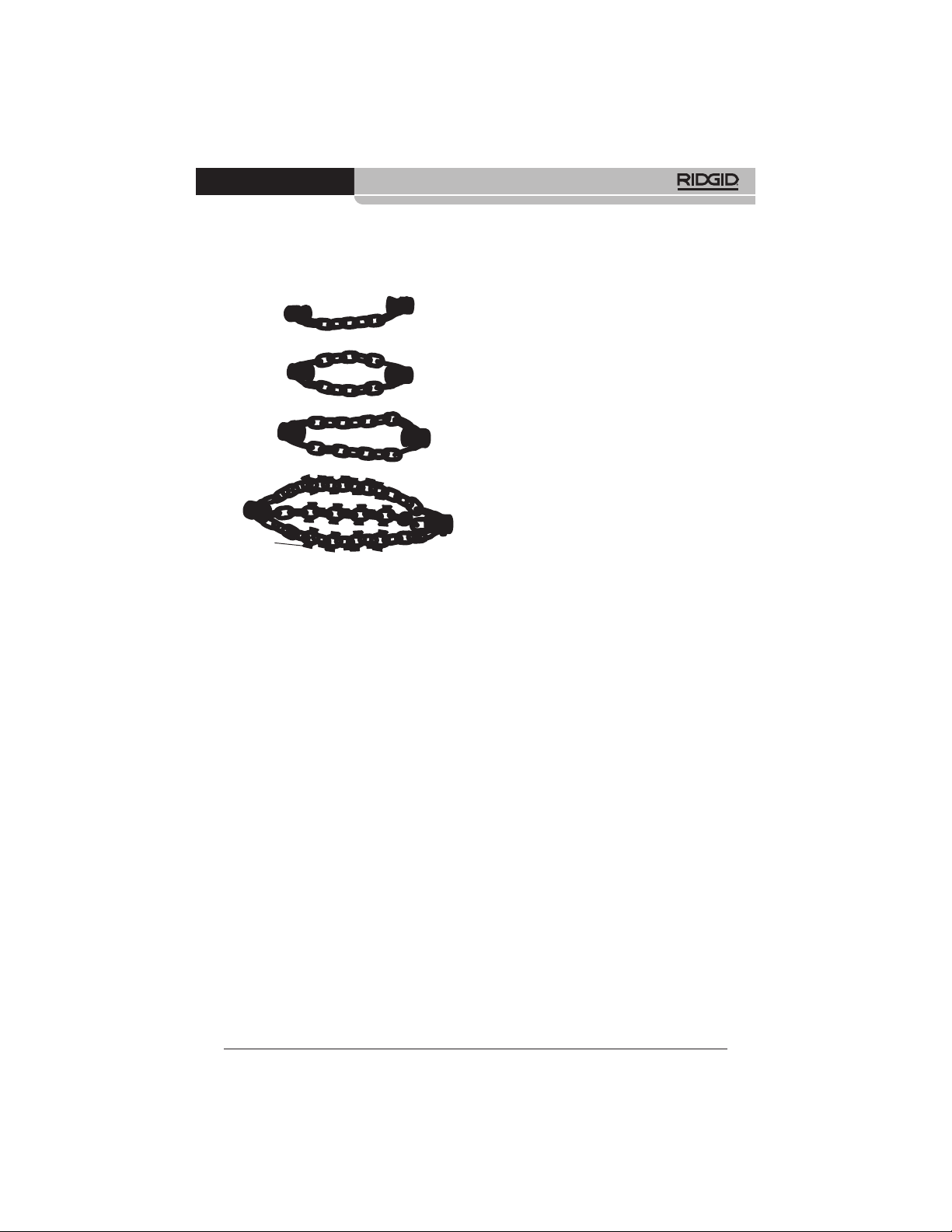
1. Select proper chain knocker for the conditions.
1 Chain
2 Chain
3 Chain
Carbide
Cutting Tips
Figure 8 – Chain Knockers
Chain knockers are sized based on col-
lar inside diameter and are designed for
specific cable sizes. ¼" chain knockers
are used on ¼" cable, etc. Do not use
a larger size chain knocker on a smaller
cable (for instance
Figure 8 and Collar Distance Chart.
Chain knockers without carbide cutting
tips can be used in common pipe types.
These chain knockers work well in grease
and similar blockages.
Chain knockers with carbide cutting tips
are used for removing scale from the
inside of the pipe and can be used for
roots. Carbide cutting tips are used for
aggressive cleaning and could damage
pipe, especially softer materials (such
as plastics and Orangeburg), thin walled
pipe, or if the chain knocker is kept in one
position for an extended time. See Figure
9, Chain Knocker Selection Chart.
Do not use chain knockers for cleaning in
glass, ceramic, porcelain or similar material fixtures or pipes. They could be
damaged.
2. Figure 10 shows a schematic of proper
chain knocker installation and adjustment.
There are two key points when installing/
adjusting chain knockers.
5
/16 " on ¼"). See
Coll
ar Distance: Set the chain knocker
collars the correct distance apart (“Collar
Distance”) to allow the chains to spread
an appropriate amount when rotated to
clean the pipe walls. Collar Distance varies based on cable size and pipe diameter, and is generally set using a spacer
made from sheath (“Collar Spacer”). If
additional flexibility is required to navigate
a bend, the collar spacer can be removed
and the collar distance can be set with a
tape measure. Operating without a collar
spacer makes it more likely for the cable
to flip over in use and be damaged. Do
not operate carbide cutters without a
collar spacer to reduce risk of cable
damage.
Exposed Cable: Minimize the amount
of exposed cable (cable not covered by
sheath). The more exposed cable there
is, the more likely the cable will flip over
in use and be damaged. Exposed cable
should be limited to no more than ¼"
(6 mm), and is set with a bushing
made from sheath (“Knocker Bushing”).
Exposed cable varies with the amount
of cable out of the drum. The more cable
out of the drum, the smaller the exposed
cable. Exposed cable may need to be set
with cable out of the drum for best results,
Sheath is supplied with
the drain cleaner
and is available as a service part to allow
configuration as needed for your specific
application. Only use RIDGID FlexShaft
Drain Cleaner sheath of the correct size
for the cable. Any time sheath is cut, it
should be cut cleanly and squarely. Do
not damage the cable when cutting the
sheath.
3. Chain knockers are retained to the cable
with set screws that use a supplied 3 mm
hex key. Loosen set screws and remove
chain knocker, spacer and bushing from
cable.
4. Inspect the sheath end for damage or
. The sheath end should be square
wear
and clean. If needed, the sheath end can
be trimmed slightly.
9
Find Quality Products Online at: [email protected]
www.GlobalTestSupply.com
Page 11

FlexShaft™ Drain Cleaning Machines
999-995-158.08_REV. C
K9-102 MACHINE
K9-204 MACHINE
CATALOG NO.
DESCRIPTION
PIPE SIZE
COPPER
GALVANIZED
CAST IRON
PVC
ABS
ORANGEBURG
CORRUGATED
CLAY
Chain Knockers
64293 64298 64283 64288 z 64323 64328 64333 64308 64313 64318
K9-102 1.5" K9-102 2"
1.25"-1.5"
(32-40 mm)
1.5"-2"
(40-50 mm)
Carbide Tipped
Chain Knockers
K9-102
K9-102
1.5"
2" CARBIDE
CARBIDE
1.25"-1.5"
(32-40 mm)
1.5"-2"
(40-50 mm)2"(50 mm)3"(75 mm)4"(100 mm)2"(50 mm)3"(75 mm)4"(100 mm)
Chain Knockers
K9-204 2" K9-204 3" K9-204 4"
Carbide Tipped Chain
Knockers
K9-204
K9-204
2"
CARBIDE
3"
CARBIDE
K9-204
4"
CARBIDE
GREASE
SOFT
BLOCKAGE
SCALING
BLOCKAGE PIPE TYPE
LIGHT ROOTS
INCLUDED
WITH KIT
Figure 9 – Chain Knocker Selection Chart
10
Find Quality Products Online at: [email protected]
www.GlobalTestSupply.com
Page 12

FlexShaft™ Drain Cleaning Machines
999-995-158.08_REV. C
Knocker
Cable Number Number of Nominal Recommended Collar
Machine
Size of Chains Links/Chain Pipe Size Distance
1
1 7 1
1
K9-102
2 7 1
K9-204 5/16"
3 13 3" (75 mm) 4" (101.6 mm)
3 15 4" (100 mm) 4
Collar Distance Chart
Knocker Bushing Knocker Collar
Sheath End
Sheath
Exposed Cable
Figure 10 – Chain Knocker Installation/Adjustment
/4"
2 9 2" (50 mm) 2
.25" (6.35 mm)
Maximum
Carbide Cutting Tip
(If Equipped)
Cable
Set Scew
(3 mm HEX)
/4" to 11/2" (32 mm to 40 mm)
1
/2" to 2" (40 mm to 50 mm)
Collar Spacer
Collar Distance
3
1
/4" (44.5 mm)
1
/2" (63.5 mm)
1
/2" (114.3 mm)
Knocker Chain
Knocker Collar
Cable End
Flush To
Set Scew
(3 mm HEX)
Collar
5. If needed, cut a section of sheath to use
as the collar spacer to the appropriate
size (See Collar Distance Chart).
Collar distance can be modified t
o your
preference for the specific pipe/application. As collar distance increases, the diameter of the chains decreases, and vice
versa. Improperly set collar distance can
reduce the efficiency of pipe cleaning.
6. Test fit the chain knock
er, knocker bushing
and collar spacer on the cable as shown
in Figure 10. Chains should be straight –
do not assemble with chains twisted. To
prevent excessive cable end wear, cable
end should be flush with the end of the
collar.
Check length of exposed cable. To reduce
the risk of cable flip over and damage,
exposed cable cannot exceed ¼" (6 mm).
If needed, cut a knocker bushing from
sheath to limit exposed cable. Always
use a knocker bushing to reduce wear
on the sheath end.
7. With the chain knocker corr
ectly installed
on the cable as shown in Figure 10, use
the supplied hex wrench to securely
tighten the collar set screws. Place set
screw tip against cable, then tighten an ad-
ditional 1/8 to 1/4 turn (45° to 90° degrees).
If the set screws are not secure, the chain
knocker could slip and damage the cable
or be lost down the drain.
Operation Instructions
WARNING
Always use safety glasses and gloves in good
condition while handling or using. Use latex or
rubber gloves, face shields, protective clothing,
respirators or other appropriate protective equipment when chemicals, bacteria or other toxic or
infectious substances are suspected to be present
to reduce the risk of infections, burns or other
serious personal injury.
Do not use with a corded drill. Operating with a
corded drill increases the risk of electrical shock.
Do not allow the chain knocker/end of cable
to stop turning while drill switch is depressed.
This can overstress the cable and may cause
twisting, kinking or breaking of the cable assembly
and may result in serious personal injury.
Practice good hygiene. Do not eat or smoke
while handling or operating the tool. After handling or operating drain cleaning equipment,
11
Find Quality Products Online at: [email protected]
www.GlobalTestSupply.com
Page 13
FlexShaft™ Drain Cleaning Machines
999-995-158.08_REV. C
use hot, soapy water to wash hands and other
body parts exposed to drain contents. This
will help reduce the risk of health hazards due to
exposure to toxic or infectious material.
Keep hand on the cable assembly whenever
the FlexShaft Machine is running. This provides
better control of the cable and helps prevent twisting, kinking and breaking of the cable and reduces
the risk of injury.
Position the FlexShaft Machine cable outlet
within 3' (1 m) of the drain inlet or properly
support exposed cable assembly when the
distance exceeds 3' (1 m). Greater distances can
cause control problems leading to twisting, kinking
or breaking of the cable. Twisting, kinking or breaking cable may cause striking or crushing injuries.
One person must control both the cable assembly and cordless drill. Do not lock drill switch
in the ON position during operation. If the cable
stops rotating, the operator must be able to release the drill switch to prevent twisting, kinking
and breaking of the cable and reduce the risk
of injury.
Follow operating instructions to reduce the
risk of injury from twisted or broken cable,
cable ends whipping around, machine tipping,
chemical burns, infections and other causes.
1. Make sure that machine and work area is
properly set-up and that the work area is
free of bystanders and other distractions.
2. Pull cable assembl
and feed into drain. At least 1' (0.3 m) of
cable must be in drain so that the chain
knocker will not come out of the drain and
whip around when the machine is started.
Directly route the cable assembly from
the machine cable outlet to the drain
opening, minimizing exposed cable and
changes in direction. Do not tightly bend
the cable assembly – this can increase
the risk of twisting or breaking.
If using a camera to view the drain clean-
ing process, the camera can be fed in
at the same time. Typically the cable assembly and the camera push rod can be
gripped and advanced/retrieved at the
same time. Keep the camera at least 1.5’
( 0.5 m) behind the chain knocker.
NOTICE
knocker to hit the camera head/push rod.
It can damage it.
3. Assume a proper operating position to
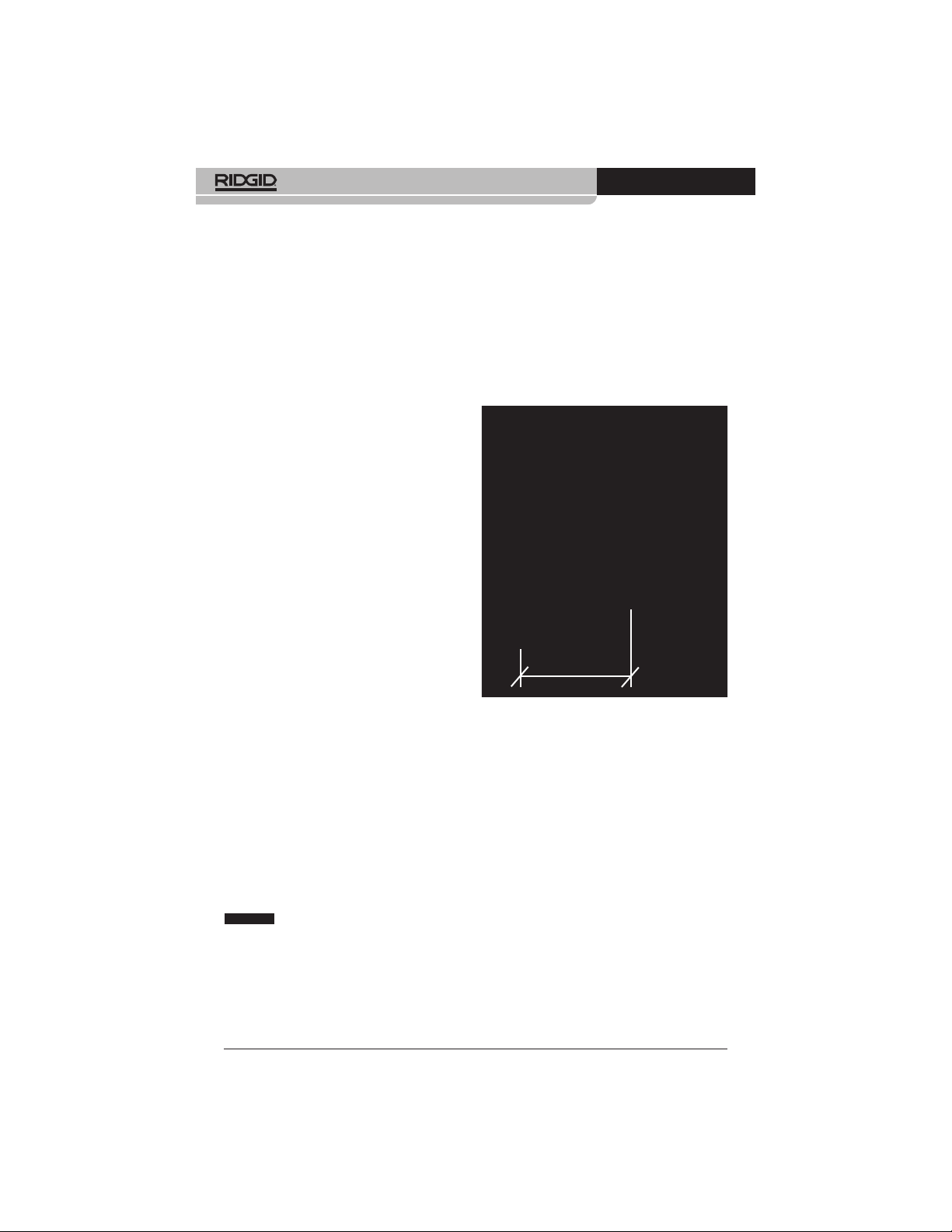
help maintain control of the cable assembly and drill (see Figure 11):
y from the machine
Do not allow the spinning chain
• Be sure you can quickl
y release the drill
switch.
• Your gloved hand m
ust be on the cable
assembly to control and support as the
cable assembly is fed into the drain and
blockage.
• Be sure that you hav
e good balance, do
not have to overreach, and cannot fall
on machine, drain, etc.. This operating
position will help to maintain control
of the cable assembly and FlexShaft
Machine.
3' (1 m) MAX.
Figure 11 – In Operating Position
4. Confirm that at least 1' (0.3 m) of cable
assembly is in the drain.
5. Confirm that the drill is properly set-up,
and depress and release the drill switch,
noting the direction of the drill chuck. Drill
rotation should match the FOR arrow on
the drum (See Figure 4). Do not rotate
the cable in reverse except as specifically
described in these instructions. Running
in reverse can damage the cable.
6. Place one hand on the cable assembly
and other hand on the drill grip.
7. The FlexShaft Drain Cleaning Machine utilizes high rotational speed and low torque
to clean drains. FlexShaft cable assemblies are more flexible than other types
of drain cleaning cables. The FlexShaft
machine is best used by applying light
pressure and slowly working the chain
knocker into the blockage when withdraw-
12
Find Quality Products Online at: [email protected]
www.GlobalTestSupply.com
Page 14

FlexShaft™ Drain Cleaning Machines
999-995-158.08_REV. C
The general operating steps for the FlexShaft Drain Cleaning Machines (see below):
1
2
3
1. Advance the chain knocker (generally not
rotating) to the area of the drain that needs
cleaned.
If the
2.
re is a blockage, pass the chain
knocker through the blockage.
If possible, star
3.
drain to carry cuttings and debris away as
the drain is cleaned.
Figure 12 – General Operating Steps
ing the cable. It’s important to let the
speed of the chain knocker clean the
drain – do not force chain knockers
into blockages.
8. Advancing/Retrieving the Cable
Assembly – FlexShaft Lubricant
In some cases it may be beneficial to
apply RIDGID FlexShaft lubricant to the
outside of the sheath when feeding the
cable down the drain. This can make it
easier to advance the cable assembly
down the drain and allow greater cleaning distance. If doing so, place a clean
towel with lubricant on it in the palm of the
gloved hand used for advancing the cable
assembly, and apply lubricant as feeding the cable assembly (Figure 13). Add
lubricant to the towel as needed during
the process. RIDGID FlexShaft markings
are printed on the sheath every 5' (1.5
m) to aid in determining how much cable
assembly has been fed from the machine.
Only use RIDGID FlexShaft lubricant.
Other lubricants may not be appropriate
for use in a drain and could contaminate
the water.
When retrieving the cable assembly, it is
good practice to use a towel to wipe dirt
t a flow of water through the
4
5
6
4. Rotate the cable/chain knocker at full speed.
5.
Continue to r
draw the cable assembly so that the chain
knocker can break up the blockage.
6. Continue to gradually withdraw the cable
assembly while rotating so that the chain
knocker can clean the walls of the drain.
and debris from the cable sheath as it is
pulled from the drain and fed back into
the drum.
9. Rotating the Chain Knocker
Generally the chain knock
cleaning while withdrawing the cable.
Only rotat
the chain knocker is at least 1' in the
drain. To rotate the cable, firmly grip the
drill handle and depress the drill switch.
The person controlling the cable assembly must also control the drill switch. Do
not operate the machine with one person
controlling the cable assembly and another person controlling the drill. Do not
allow cable assembly to build up outside
the drain, bow or curve. This can lead
to twisting, kinking and breaking of the
cable. At any time, release the drill trigger to stop cable rotation. When clearing
blockages, operate the cable at full speed
for best cleaning. Do not force the chain
knocker into blockages. In some cases,
using variable speed will assist with navigating turns. Rotating the chain knocker in
FORWARD or REVERSE for a short time
while advancing the cable assembly can
help it negotiate the drain and blockages.
otate knocker. Gradually with-
er is rotated for
e the cable/chain knocker when
13
Find Quality Products Online at: [email protected]
www.GlobalTestSupply.com
Page 15

FlexShaft™ Drain Cleaning Machines
999-995-158.08_REV. C
Figure 13 – Applying Lubricant to the Cable
10. Advance the cable assembly into the
drain, generally not rotating. Grasp the
sheath near where it exits the machine
housing. Pull 6" to 12" (150 to 300 mm)
of cable assembly out of the FlexShaft
Machine so that there is a slight bow in
the cable. Gloved hand must be on cable
assembly to control and support. Improper
cable support can allow the cable assembly to kink or twist and can damage
the cable or injure the operator. Feed the
cable assembly into the drain (Figure 12,
Step 1).
11. Continue to adv
bly until the resistance is encountered.
Carefully work the chain knocker through
the blockage. Do not force the cable
assembly – if the chain knocker cannot turn, it cannot clean the drain. Pay
attention to how far the cable has gone.
Do not overrun the cable into a larger
drain. This can cause the cable to knot
up or cause other damage (Figure 12,
Step 2).
12. If possible, start a flow of water down the
drain to flush the debris out of the line
and help clean the cable assembly as it is
retrieved. This can be done by turning on
a faucet in the system or other methods.
Pay attention to the water level, as the
drain could plug again (Figure 12, Step 3).
13. With the chain knocker past the b
area to be cleaned, fully depress the drill
switch to rotate the chain knocker. Slowly
Sheath
ance the cable assem-
lockage/
pull the cable assembly from the drain, allowing the rotating chain knocker to clean
the drain walls and break up the blockage
(Figure 12, Steps 4 & 5). If the cable
stops turning, do not continue operating the drill. This may cause the cable to
twist and kink. At any time, release the drill
switch to stop cable rotation.
Monitor the feedback from the feel of the
cable assembly in your hand and the
sound of the drill/knocker in the drain. If
the drill clutch disengages, the cable has
likely stopped turning. See Drill Adjustable
Clutch Setting in Set-up section. Do not
place the battery drill torque adjustment
in the “drill” setting. This increases the
force that is felt at the drill handle, and can
cause the drill to spin around. Firmly grip
the drill handle to maintain control.
It may be necessary to mo
knocker out of the blockage to allow it to
come back up to speed.
If the chain knocker becomes stuck, it
may be able to be freed by running the
drill in reverse for a short time. Do not run
in reverse for more than a few seconds to
prevent cable damage. In some cases, it
may be possible to pull the cable assembly
and the blockage out of the drain by hand.
If this is done, be careful to not damage
the cable assembly. Remove the blockage
from the knocker and cable and continue
cleaning the drain as detailed above.
If using with a camera, do not run the
chain knocker into the camera head or
push rod.
In some cases, to clean the opposite side
of the pipe it may help to run the drill in
REVERSE for a short time.
14. Continue to clean the r
while retrieving the cable. Once the drain
has been cleaned, retrieve the cable and
feed back onto the drain cleaning machine. Pay close attention, as the cable
may lodge in a blockage while being retracted (Figure 12, Step 6).
15. Watch for your sheath marking as the
cable assembly is retrieved. Release
the drill switch when the chain knocker
nears drain opening. Do not pull the chain
knocker from drain while it is rotating. The
chain knocker can whip around and could
cause serious injury.
16. If needed for complete cleaning, r
the above procedure.
ve the chain
est of the drain
epeat
14
Find Quality Products Online at: [email protected]
www.GlobalTestSupply.com
Page 16
FlexShaft™ Drain Cleaning Machines
999-995-158.08_REV. C
17. Pull any remaining cable assembly from
the line by hand and push back into the
drum. Prepare the machine for transport.
Draining the Drum
If needed, the drain cleaner can be turned to
allow any liquid in the housing to be drained
(see Figure 1 for drain hole location).
Transportation
Feed all of cable assembly into the drum
and secure the chain knocker in the hook.
Remove the drill from the drill shaft. Do not
leave the drill attached during transport to
prevent tipping and damage to the drain
cleaner. See Figure 1.
Storage
WARNING
must be kept dry and indoors or well covered if kept outdoors. Store the machine in
a locked area that is out of reach of children
and people unfamiliar with drain cleaning
machines. This machine can cause serious
injury in the hands of untrained users.
The Drain Cleaning Machine
Maintenance
Instructions
WARNING
Drill should be removed from drain
cleaner before any maintenance is performed.
Always wear safety glasses and other
appropriate protective equipment when
performing any maintenance.
Cable Assembly Replacement
1. Pull entire cable assembly from housing.
2. Remove the f
ing closed (4 mm hex wrench) and open
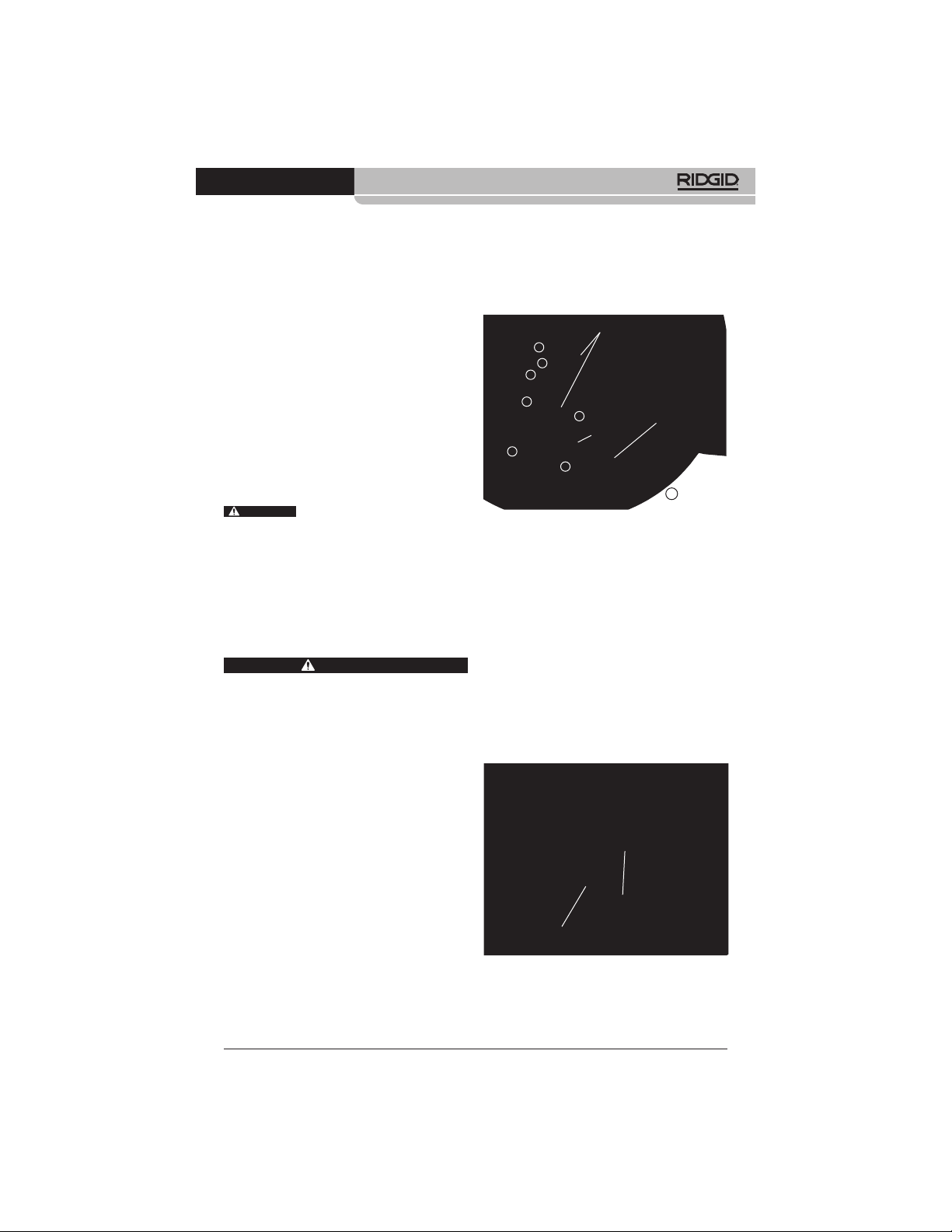
the housing (Figure 14).
Figure 14 – Drain Cleaner Housing Opened
3. Remove retention plate fasteners and retention plate (Figure 14).
4. Loosen gear box plate fasteners 3-4 turns
but do not remove. (4 mm hex wrench).
5. Remove the detent pin from the cable
coupling.
6. Remove the cable coupling from the gear
box shaft and remove the cable assembly.
Lift the gearboxes slightly to allow cable
coupling removal.
7. Reverse process to assemble, securely
attaching all fasteners. Ensure sheath is
tight to the stop in the drum cable slot to
minimize exposed cable (see Figure 15).
asteners holding the hous-
Gear Boxes
Retention
Detent Pin
Plate
Gear Box
Fastener
Plate
Cleaning
It is good practice to use a towel to wipe dirt
and debris from the sheath as the cable assembly is pulled from the drain and fed back
into the drum. This will help to keep the drum
clean and reduce the likelihood of the cable
Sheath Tight
To Stop
assembly sticking in the drum. If needed,
cable assembly can be pulled from the machine and the housing opened for flushing/
cleaning.
Clean the machine as needed with hot soapy
water and/or mild disinfectants. Drain the machine as needed.
Cable Coupling
Figure 15 – Changing the Cable Assembly
Lubrication
The FlexShaft Drain Cleaning Machines are
lubricated for life from the factory.
15
Find Quality Products Online at: [email protected]
www.GlobalTestSupply.com
Page 17

FlexShaft™ Drain Cleaning Machines
999-995-158.08_REV. C
Troubleshooting
SYMPTOM POSSIBLE REASON SOLUTION
Cable kinking or
breaking.
FlexShaft Machine
wobbles or moves
while cleaning drain.
Cable assembly is being forced..
Incorrect FlexShaft Machine or chain
knocker used for pipe diameter.
Drill being run in reverse.
Cable assembly exposed to acid/
corroded.
Cable/sheath worn out.
Cable assembly not properly
supported.
Chain knocker not properly set up/
adjusted
Improper drill or drill settings.
Ground not level.
Do no force cable assembly. Follow operating instructions.
Use correct FlexShaft Machine or chain
knocker for pipe size.
Use reverse only if flex shaft gets
caught in pipe.
Clean cable assembly routinely.
Replace worn cable assembly.
Support cable assembly properly, see
instructions.
Properly set up/adjust chain knocker,
see instructions.
Choose proper drill and settings, see
instructions.
Place on level stable surface.
Service and Repair
WARNING
Improper service or repair can make
the machine unsafe to operate.
The “Maintenance
Instructions” will take
care of most of the service needs of this machine. Any problems not addressed by this
section should only be handled by a RIDGID
Independent Service Center. Use only
RIDGID service parts.
Optional Equipment
WARNING
To reduce the risk of serious injury,
only use accessories specifically designed and recommended for use with
the RIDGID FlexShaft Drain Cleaning
Machine, such as those listed.
Catalog
No. Description
64283 Knocker, 1/4" cable, 11/2"-2" pipe, single chain,
carbide tip
64288 Knocker, 1/4" cable, 2" pipe, 2 chain, carbide tip
64293 Knocker, 1/4" cable, 11/2"-2" pipe, single chain
64298 Knocker, 1/4" cable, 2" pipe, 2 chain
64308 Knocker, 5/16" cable, 2" pipe, 2 chain, carbide tip
64313 Knocker,
5
/16" cable, 3" pipe, 3 chain, carbide tip
64318 Knocker, 5/16" cable, 4" pipe, 3 chain, carbide tip
64323 Knocker, 5/16" cable, 2" pipe, 2 chain
64328 Knocker,
5
/16" cable, 3" pipe, 3 chain
64333 Knocker, 5/16" cable, 4" pipe, 3 chain
64338 FlexShaft Lubricant, 8 oz, 12 per case
64343 1/4" Assembly, cable, sheath, couplings, 50'
64348 5/16" Assembly, cable, sheath, couplings, 70'
64363 1
64368 1
1
/4" RIDGID Wallpipe Accessory
1
/2" RIDGID Wallpipe Accessory
16
Find Quality Products Online at: [email protected]
www.GlobalTestSupply.com
Page 18

FlexShaft™ Drain Cleaning Machines
999-995-158.08_REV. C
Disposal
Parts of these tools contain valuable materials and can be recycled. There are companies that specialize in recycling that may be
found locally. Dispose of the components in
compliance with all applicable regulations.
Contact your local waste management authority for more information.
17
Find Quality Products Online at: [email protected]
www.GlobalTestSupply.com
Page 19
EC Declaration
RIDGID
®
K9-102 & K9-204 FlexShaft Drain Cleaning
Machines
EC DECLARATION OF CONFORMITY
We declare that the machines listed above, when used in accordance with the operator’s manual, meet the relevant
require-ments of the Directives and Standards listed below.
Signature:
2006/42/EC
Find Quality Products Online at: [email protected]
www.GlobalTestSupply.com
Name: Harald Krondorfer
Qualification: V.P. Engineering
Date: 06/30/2019
Page 20
FULL LIFETIME WARRANTY
Against Material Defects
& Workmanship
FULL LIFETIME WARRANTY (legal warranty extended to the product lifecyle,
see warranty conditions)
Printed 12/19 999-995-158.08
EC44010/04 REV. C
Find Quality Products Online at: [email protected]
The Emerson logo and RIDGID logo are registered trademarks of Emerson Electric Co. or RIDGID, Inc. in the U.S. and other countries.
www.GlobalTestSupply.com
©2019 RIDGID, Inc.
All other trademarks belong to their respective holders.
 Loading...