

Page 1

Operator’s Manual
nano
TM
WARNING!
Read this Operator’s Manual carefully before using
this tool. Failure to understand and follow the contents of this manual may
result in electrical shock,
fire and/or serious personal injury.
Find Quality Products Online at: [email protected]
www.GlobalTestSupply.com
Page 2

nano
TM
Table of Contents
Recording Form for Machine Serial Number ���������������������������������������������������������������������������������������������������������������� 1
Safety Symbols ����������������������������������������������������������������������������������������������������������������������������������������������������������������3
General Safety Rules �������������������������������������������������������������������������������������������������������������������������������������������������������3
Work Area Safety ����������������������������������������������������������������������������������������������������������������������������������������������������������3
Electrical Safety ������������������������������������������������������������������������������������������������������������������������������������������������������������3
Personal Safety�������������������������������������������������������������������������������������������������������������������������������������������������������������3
Equipment Use and Care ���������������������������������������������������������������������������������������������������������������������������������������������3
Service �������������������������������������������������������������������������������������������������������������������������������������������������������������������������4
Specific Safety Information ��������������������������������������������������������������������������������������������������������������������������������������������4
SeeSnake nanoReel Safety
Description, Specifications, and Standard Equipment
Description �������������������������������������������������������������������������������������������������������������������������������������������������������������������5
Specifications ���������������������������������������������������������������������������������������������������������������������������������������������������������������5
Standard Equipment �����������������������������������������������������������������������������������������������������������������������������������������������������5
nanoReel Components ���������������������������������������������������������������������������������������������������������������������������������������������������6
Icon Legend ������������������������������������������������������������������������������������������������������������������������������������������������������������������6
Assembly �������������������������������������������������������������������������������������������������������������������������������������������������������������������������� 7
Camera Head Routing �������������������������������������������������������������������������������������������������������������������������������������������������� 7
Installing System Cable ������������������������������������������������������������������������������������������������������������������������������������������������ 7
Reversing/Installing the Display Cradle (micro CA‑300 inspection Camera) ����������������������������������������������������������������8
Connecting the micro CA‑300 Inspection Camera to the nanoReel System �����������������������������������������������������������������8
nanoReel Ball Guides ���������������������������������������������������������������������������������������������������������������������������������������������������8
Pre-Operation Inspection �����������������������������������������������������������������������������������������������������������������������������������������������9
Work Area and Equipment Set Up ����������������������������������������������������������������������������������������������������������������������������������9
Setting Up the nanoReel ���������������������������������������������������������������������������������������������������������������������������������������������10
Operating Instructions ���������������������������������������������������������������������������������������������������������������������������������������������������11
Locating the nanoReel Sonde ������������������������������������������������������������������������������������������������������������������������������������13
Retrieving the Camera ����������������������������������������������������������������������������������������������������������������������������������������������� 13
Using Guide Tubes ����������������������������������������������������������������������������������������������������������������������������������������������������� 13
Cleaning ������������������������������������������������������������������������������������������������������������������������������������������������������������������������� 14
Accessories ��������������������������������������������������������������������������������������������������������������������������������������������������������������������14
Transport and Storage ��������������������������������������������������������������������������������������������������������������������������������������������������14
Service and Repair �������������������������������������������������������������������������������������������������������������������������������������������������������� 15
Disposal ������������������������������������������������������������������������������������������������������������������������������������������������������������������������� 15
Troubleshooting �������������������������������������������������������������������������������������������������������������������������������������������������������������15
�����������������������������������������������������������������������������������������������������������������������������������������4
������������������������������������������������������������������������������������������������5
2 – English
Find Quality Products Online at: [email protected]
www.GlobalTestSupply.com
Page 3
nano
TM
Safety Symbols
In this operator’s manual and on the product, safety symbols and signal words are used to communicate important safety information. This section is provided to improve understanding of these signal words and symbols.
This is the safety alert symbol� It is used to alert you to potential personal injury hazards� Obey all safety messages that follow
this symbol to avoid possible injury or death�
DANGER
WARNING
CAUTION
NOTICE
This symbol means read the operator’s manual carefully before using the equipment� The operator’s manual contains important
information on the safe and proper operation of the equipment�
This symbol means always wear safety glasses with side shields or goggles when handling or using this equipment to reduce
the risk of eye injury�
This symbol indicates the risk of electrical shock�
DANGER indicates a hazardous situation which, if not avoided, will result in death or serious injury�
WARNING indicates a hazardous situation which, if not avoided, could result in death or serious injury�
CAUTION indicates a hazardous situation which, if not avoided, could result in minor or moderate injury�
NOTICE indicates information that relates to the protection of property�
General Safety Rules
WARNING
Read all safety warnings and instructions. Failure
to follow the warnings and instructions may result
in electric shock, re, and/or serious injury.
SAVE THESE INSTRUCTIONS!
Work Area Safety
• Keep your work area clean and well lit. Cluttered or
dark areas invite accidents�
• Do not operate equipment in explosive atmo-
spheres, such as in the presence of flammable
liquids, gases, or dust. Equipment can create
sparks which may ignite the dust or fumes�
• Keep children and bystanders away while operat-
ing equipment. Distractions can cause you to lose
control�
Electrical Safety
• Avoid body contact with earthed or grounded
surfaces such as pipes, radiators, ranges, and refrigerators. There is an increased risk of electrical
shock if your body is earthed or grounded�
• Do not expose equipment to rain or wet condi-
tions. Water entering equipment will increase the risk
of electrical shock�
• If operating equipment in a damp location is un-
avoidable, use a ground fault circuit interrupter
(GFCI) protected supply. Use of a GFCI reduces the
risk of electric shock�
• Keep all electrical connections dry and off the
ground. Do not touch equipment or plugs with wet
hands to reduce the risk of electrical shock�
Personal Safety
• Stay alert, watch what you are doing, and use
common sense when operating equipment. Do
not use equipment while you are tired or under the
influence of drugs, alcohol, or medication� A moment
of inattention while operating equipment may result in
serious personal injury�
• Use personal protective equipment. Always wear
eye protection� The appropriate use of protective
equipment such as a dust mask, non‑skid safety
shoes, a hard hat, and hearing protection will reduce
personal injuries�
• Do not overreach. Keep proper footing and balance
at all times� This enables better control of the equip‑
ment in unexpected situations�
• Dress properly. Do not wear loose clothing or jew‑
elry� Keep your hair, clothing, and gloves away from
moving parts� Loose clothes, jewelry, and long hair
can be caught in moving parts�
• Do not abuse the cord. Never use the cord for carry‑
ing, pulling, or unplugging the power tool� Keep cord
away from heat, oil, sharp edges, and moving parts�
Damaged or entangled cords increase the risk of
electric shock�
Find Quality Products Online at: [email protected]
www.GlobalTestSupply.com
Equipment Use and Care
• Do not force equipment. Use the correct equipment
for your application� The correct equipment will do the
job better and safer at the rate for which it is designed�
English – 3
Page 4

nano
TM
• Do not use equipment if the power switch does
not turn it ON and OFF. Any equipment that cannot
be controlled with the power switch is dangerous and
must be repaired�
• Disconnect the plug from the power source and/
or the battery pack from the equipment before
making adjustments, changing accessories, or
storing. Preventive safety measures reduce the risk
of injury�
• Store idle equipment out of the reach of chil-
dren and do not allow persons unfamiliar with
the equipment or these instructions to operate
the equipment. Equipment can be dangerous in the
hands of untrained users�
• Maintain equipment. Check for misalignment or
binding of moving parts, missing parts, breakage
of parts, and any other condition that may affect the
equipment’s operation� If damaged, have the equip‑
ment repaired before use� Many accidents are caused
by poorly maintained equipment�
• Use the equipment and accessories in accor-
dance with these instructions; taking into account the working conditions and the work to be
performed. Use of the equipment for operations dif‑
ferent from those intended could result in a hazard‑
ous situation�
• Use only accessories that are recommended by
the manufacturer for your equipment. Accessories
that may be suitable for one piece of equipment may
become hazardous when used with other equipment�
• Keep handles dry, clean, and free from oil and
grease. This allows for better control of the equip‑
ment�
Service
Ensure a qualified repair person services your equipment
using only identical replacement parts to maintain
the safety of the tool� Remove the batteries and refer
servicing to qualified service personnel under any of the
following conditions:
• If liquid has been spilled or objects have fallen into
product�
• If the product does not operate normally when
following the operating instructions�
• If the product has been dropped or damaged�
• When the product exhibits a distinct change in
performance�
Specic Safety Information
WARNING
This section contains important safety informa‑
tion that is specic to the nanoReel. Read these
precautions carefully before using the nanoReel to
reduce the risk of electrical shock, re, or other
serious personal injury.
SAVE ALL WARNINGS AND INSTRUCTIONS
FOR FUTURE REFERENCE!
Keep this manual with the equipment for use by the operator�
SeeSnake nanoReel Safety
• An improperly grounded electrical outlet can
cause electrical shock and/or severely damage
equipment. Always check work area for a properly
grounded electrical outlet� Presence of a three‑prong
or GFCI outlet does not ensure that the outlet is prop‑
erly grounded� If in doubt, have the outlet inspected
by a licensed electrician�
• Do not operate this equipment if operator or nano-
Reel is standing in water. Operating the nanoReel
while in water increases the risk of electrical shock�
• The nanoReel system camera and push cable are
waterproof. The monitor and other electrical equip‑
ment and connections are not waterproof� To de‑
crease the risk of electrical shock, do not expose the
equipment to water or rain�
• Do not use where a danger of high voltage con-
tact is present. The equipment is not designed to
provide high voltage protection and isolation�
• Read and understand this operator’s manual, the
reel operator’s manual, the instructions for any
other equipment in use and all warnings before
operating the nanoReel. Failure to follow all instruc‑
tions and warnings may result in property damage
and/or serious personal injury�
• Always use appropriate personal protective
equipment when handling and using equipment
in drains. Drains may contain chemicals, bacteria,
and other substances that may be toxic, infectious,
cause burns or other issues� Appropriate personal
protective equipment always includes safety glasses
and may include drain cleaning gloves or mitts, latex
or rubber gloves, face shields, goggles, protective
clothing, respirators, and steel toed footwear�
• If using drain cleaning equipment at the same
time as drain inspection equipment, only wear
RIDGID drain cleaning gloves. Never grasp the ro‑
tating drain cleaning cable with anything else, includ‑
ing other gloves or a rag which can become wrapped
around the cable and cause hand injuries� Only wear
latex or rubber gloves under RIDGID drain cleaner
4 – English
Find Quality Products Online at: [email protected]
www.GlobalTestSupply.com
Page 5
nano
TM
gloves� Do not use damaged drain cleaning gloves�
• Practice good hygiene. Use hot, soapy water to
wash hands and other body parts exposed to drain
contents after handling or using drain inspection
equipment� To prevent contamination from toxic or in‑
fectious material, do not eat or smoke while operating
or handling drain inspection equipment�
The information supplied with this product cannot
cover all possible conditions and situations that may
occur, and should be used in conjunction with appropriate training, sound judgment, and good work practices. These factors cannot be built into the product,
but must be supplied by the operator.
The EC Declaration of Conformity (890‑011‑320�10) will
accompany this manual as a separate booklet when re‑
quired�
Description, Specications, and
Standard Equipment
Description
The nanoReel is a modern, portable SeeSnake diagnostic
reel and camera that has the flexibility and adaptability
to view small pipes, tubes, voids, and conduits� It
contains a unique, removable cable drum which makes
cleaning and replacing push cables convenient� Since
the nanoReel comes with a removable system cable, it
can be used with any SeeSnake camera control unit or
with the hand‑held micro CA‑300 inspection camera�
The nanoReel uses an advanced push cable design
and a proprietary small radius camera design which
allows camera inspection through pipes with very small
diameters, P‑traps, and very small radius bends which
conventional inspection systems often cannot inspect�
When using the nanoReel with an appropriate SeeSnake
control unit, the operator can connect an external line
transmitter and use a standard locator to line‑trace the
path of the nanoReel push cable in a pipe�
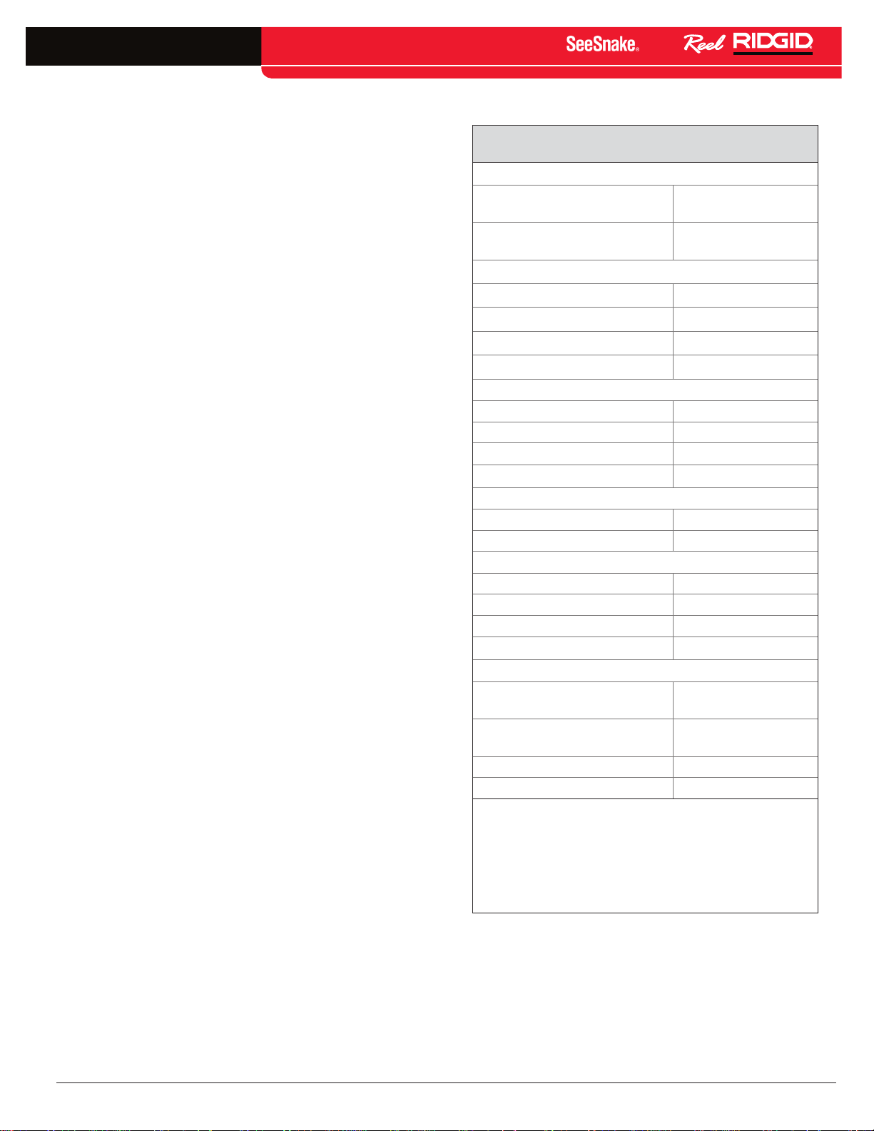
Specications
Table 1
SeeSnake nanoReel Specifications
Weight
Dimensions:
Camera specifications:
Sonde
Lighting
Resolution:
Push cable:
Bend radius
Pipe capacity*
Operating environment:
* The nanoReel will traverse a 1 in [25 mm] straight
:
with micro CA‑300
inspection camera
without micro CA‑300
inspection camera
Length 13�25 in [33�6 cm]
Depth 6�6 in [16�7 cm)
Height 14�2 in [36 cm]
Frame diameter 12�75 in [32 cm]
Length 0�88 in [22�5 mm]
Diameter 0�61 in [15�5 mm]
NTSC 656 × 492 pixels
PA L 768 × 576 pixels
Length 82 ft [25 m]
Diameter
Temperature
Storage temperature
Humidity 5% – 95% RH
Waterproof depth 225 ft [70 m]
pipe, but its ability to go past 90‑degree turns will
depend on the material and construction of individual
pipes and joints� Test the material you intend to
inspect to ensure the camera can pass through turns
successfully� Some fittings in small diameter joints will
allow passage of the camera in only one direction�
14�65 lb [6�6 kg]
9�15 lb [4�1 kg]
512 Hz
6 LEDs
0�25 in [6�3 mm]
1 in [25 mm]
1 in [25 mm]
32°F – 115°F
[0°C – 46°C]
−4°F – 158°F
[−20°C – 70°C]
Standard Equipment
• nanoReel
• Operator’s Manual
• Instructional DVD
• Ball Guides (two sizes)
English – 5
Find Quality Products Online at: [email protected]
www.GlobalTestSupply.com
Page 6
nano
TM
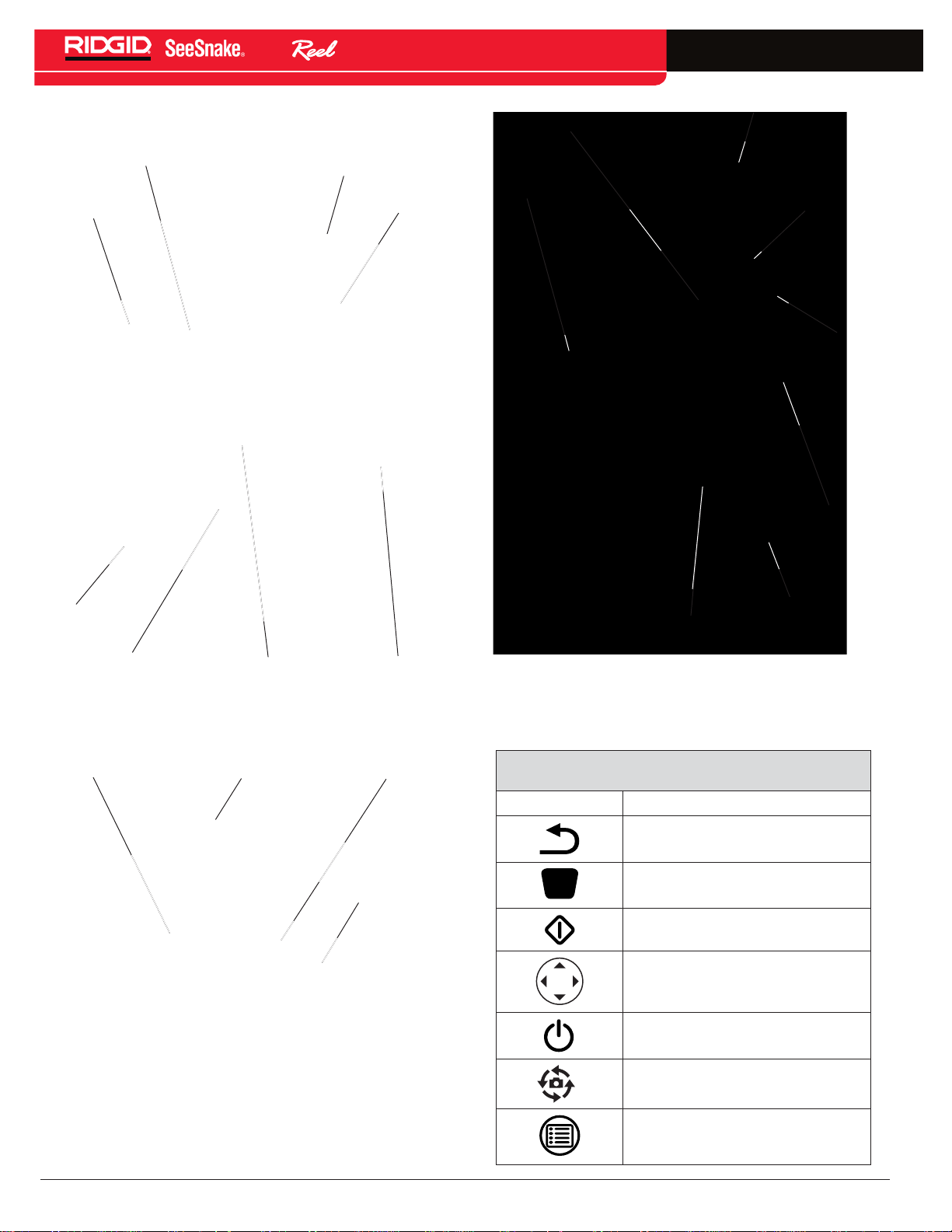
nanoReel Components
Push Cable Guide
Front Case
System Cable for
SeeSnake CCU
Case Latch
System Cable for
micro CA‑300
Case Latch
micro CA‑300 Camera Monitor
micro CA‑300
Connector
Plug
Cord Wrap
Rear Case
Feet
Camera Head
Camera Clip
Rear Case
Figure 1 – Front View (SeeSnake Configuration)
Case Latch Camera Head
Push Cable
Removable
Push Cable
Drum
Figure 2 – Inside Case
Feet
Slip‑Ring Module
Figure 3 – Rear View (with the micro CA -300
inspection camera)
Icon Legend
Table 2
micro CA-300 Icons
Icon
Meaning
Return Key
Shutter Key
Select Key
Arrow Keys
Power Key
Rotate Image Key
Menu Key
6 – English
Find Quality Products Online at: [email protected]
www.GlobalTestSupply.com
Page 7

Assembly
WARNING
To reduce the risk of serious injury, properly assem‑
ble the nanoReel in accordance with these proce‑
dures.
Camera Head Routing
1� Set the unit on a level surface and lay it on its back�
2� Unfasten the case latches on either side of the
nanoReel (See Figure 4)�
nano
TM
Figure 4 – Unlatching the nanoReel Case
3� Open the front case and locate the camera head in
the push cable drum�
4� Route the camera head out through the push cable
guide in the front of the case (See Figure 5).
5� Secure the camera head in the provided clip (See
Figure 6).
6� Close and relatch the case�
Figure 6 – Camera Head Properly Routed
Installing System Cable
NOTICE
ring module or insert any tool inside the well where the
pins are located. Avoid stressing or breaking the contact
pins.
To avoid breaking the contact pins, do not press sideways
on the pins (See Figure 7).
Do not touch the contact pins inside the slip-
Figure 7 – Broken Contact Pin
If the system cable slip‑ring module is not installed, insert
the slip‑ring module into the hub (See Item 1, Figure 8)�
Twist the slip‑ring module clockwise until it locks into
Figure 5 – Routing the Camera Head
position (See Item 2, Figure 8)�
English – 7
Find Quality Products Online at: [email protected]
www.GlobalTestSupply.com
Page 8

nano
TM
1
2
Figure 8 – Locking the Slip-Ring Module Cover
Reversing/Installing the Display Cradle
(micro CA‑300 Inspection Camera)
If using the nanoReel with the micro CA‑300, it may
be more convenient to face the micro CA‑300 display
the other way when seated in its cradle� To reverse the
orientation of the cradle, perform the following:
1� Remove the micro CA‑300 from the cradle (See
Item 1, Figure 9)� Use a Philips screwdriver to
remove the four screws holding the cord wrap arms
and the cradle’s support arms to the case openings
(See Item 2 and Item 3, Figure 9)� Remove the
cord‑wrap arms after removing the screws�
4� Unthread the screw� Repeat for each of the
remaining three nuts�
5� Position the cord‑wrap arm and cradle on the same
side of the case, facing in the opposite direction�
Make sure the cord‑wrap horns point outward�
6� Start each screw into its nut by hand� Tighten the
screws hand‑tight with a screwdriver�
7� Replace the display unit in the cradle�
Install the display cradle using a similar process�
Connecting the micro CA‑300 Inspection
Camera to the nanoReel System
Align the micro CA‑300 Camera Connector Plug with the
plug on the micro CA‑300 Camera, slide it straight in,
and seat it squarely� The curved face of the connector
plug on the system cable faces upward, sliding under
the forward edge of the micro CA‑300 camera monitor
when fully seated (See Figure 10)�
NOTICE
the connector plug.
To prevent damaging the plug, do not twist
1
2
3
Figure 9 – Cradle Support and Cord-Wrap Arms
2� Use one of the screws to remove the nuts from
the backside of the cradle� The nuts are friction‑
fitted into the holes on the opposite side of the
cradle from the cord‑wrap arms� Extract the nut by
inserting a screw from the back and threading it
two or three turns into the nut�
3� Without taking the nut off, insert the screw and nut
into the hole on the opposite side of the case� Tap
the screw firmly with the handle of the screwdriver
to seat the nut into the friction‑fit at the bottom of
the hole�
Figure 10 – Connecting the micro CA-300 Camera
Monitor
nanoReel Ball Guides
Ball guides help center the camera in pipes and keeps
the camera clear of bottom sludge in the pipe� Ball
guides also improve picture quality, allows the camera
to see equally in all directions, and keeps the lens free
of sludge by bringing the camera closer to the center of
the pipe�
Figure 11 – Ball Guide in Use
8 – English
Find Quality Products Online at: [email protected]
www.GlobalTestSupply.com
Page 9

nano
TM
Use ball guides whenever possible to reduce wear and
tear on the camera system� Ball guides can be easily
removed or adjusted to allow for better movement in
pipes as needed� For example, placing two ball guides
near the front end of the camera may bias the camera
head upward to allow better viewing of the top of the
pipe during an inspection� Ball guides can also help
negotiate some passages, such as those shown in the
Operating Instructions of this manual�
The nanoReel has two different ball guides: a clip‑on ball
guide and a smaller guide called a Camera Head Pipe
Guide�
Installing Ball Guides
The ball guides are designed to slip easily onto the
camera spring and lock into place� The ball guide has two
red sliding locks and two blue latches (See Figure12).
Figure 12 – Ball Guide Installation
Install the ball guides in accordance with the following:
1� Slide the red sliding locks away from the blue
latches on both sides of the guide�
2� Press the small tabs on the blue latches so they
click outward (away from each other)�
Pre‑Operation Inspection
WARNING
Before each use, inspect your nanoReel and cor‑
rect any problems to reduce the risk of serious in‑
jury from electrical shock or other causes and pre‑
vent machine damage.
1� Confirm that the power is OFF� If using the
nanoReel with a camera control unit (CCU) other
than the micro CA‑300, confirm that the CCU is not
connected to the unit� Inspect the system cable and
connectors for damage or modification�
2� Clean any dirt, oil, or other contamination from the
nanoReel to aid in inspection and to prevent the
unit from slipping from your grip during transport
or use�
3� Inspect the nanoReel for any broken, worn, missing,
misaligned, or binding parts, or any other condition
that might prevent safe, normal operation� Confirm
that the unit is properly assembled� Make sure that
the drum turns freely� Inspect the push cable for
any cuts, breaks, kinks, or ruptures�
4� Inspect any other equipment being used to ensure
it is in good, usable condition as specified by the
manufacturer�
5� Correct any problems before use�
3� Slide the ball guide into position over the camera
head�
Work Area and Equipment Set Up
WARNING
4� Press down on the shoulders of the blue latches so
the latches are pressed in toward each other and
lock into the spring�
5� Slide the two red sliding locks back over their
respective blue latches so they cannot pop out
while in use�
For smaller pipes, tubes, or voids, the Camera Head
Pipe Guide may be installed in lieu of the clip‑on ball
guide� To install the Camera Head Pipe Guide perform
the following�
1� Unscrew the two securing screws holding the two
halves of the ball guide together�
Set up and operate the nanoReel and work area in
accordance with these procedures to reduce the
risk of injury from electrical shock, re, crushing
injuries, and other causes, and to prevent damage
to the nanoReel.
Always wear eye protection to protect your eyes
against dirt and other foreign objects.
1� Check work area for the following:
2� Seat the two halves around the camera head with
their screw‑holes aligned�
3� Fasten the two halves together with the two screws
provided� Do not over‑tighten�
• Adequate lighting�
• Flammable liquids, vapors, or dust that may ignite� If
present, do not work in area until sources have been
identified and corrected� The nanoReel is not explosion
English – 9
Find Quality Products Online at: [email protected]
www.GlobalTestSupply.com
Page 10

nano
proof� Electrical connections can cause sparks�
• Clear, level, stable dry place for machine and operator�
Do not use the machine while standing in water� If
required, remove the water from the work area� Ensure
the nanoReel is stable�
• Clear path to electrical outlet if used for monitor, that
does not contain any potential sources of damage for
the power cord�
TM
2� If possible, inspect the work to be done� Determine
the drain access points, sizes, and lengths, and the
presence of chemicals� If chemicals are present,
understand the specific safety measures required
to work around those chemicals� Contact the
chemical manufacturer for required information�
2
1
Figure 13 – Connecting to a SeeSnake CCU
3� If needed, remove fixtures such as the water closet
or sink, to obtain better access�
4� Determine the correct equipment for the application�
The nanoReel is designed for lines no greater than
80 ft [24�4 m] long and for lines with diameters from
1 in to 3 in [25�4 mm to 76�2 mm]�
5� Properly inspect all equipment�
6� Evaluate the work area and use barriers to keep
bystanders away as needed� Bystanders can
distract the operator during use� If working near
traffic, erect cones or other barriers to alert drivers�
Setting Up the nanoReel
Connections
When using the nanoReel with a micro CA‑300, no
additional connections beyond those described in the
assembly section are needed when setting up the unit
for an inspection�
To use the nanoReel with a SeeSnake CCU perform the
following:
1� Unwrap the SeeSnake System Cable from its holder,
pull back the locking sleeve, and match the System
Cable plug to the matching SeeSnake System
Connector on the CCU (See Item 1, Figure13)�
2� To join the connectors, align the guide pin to the
guide socket, push the connector straight in� A
guide ridge molded into the top of the cable
connector will point up when the plug is correctly
aligned (See Item 2, Figure 13)�
NOTICE
tem Cable, twist only the locking sleeve! To prevent damage to pins, never bend or twist the connector or cable!
When connecting or disconnecting the Sys-
The nanoReel can be used with any SeeSnake CCUs by
changing the system cable as specified in the assembly
section�
Set up the micro CA‑300 or CCU in accordance with
its instructions� If using the micro CA‑300 or a battery
powered CCU, make sure that the required batteries are
fully charged and installed�
Placement
1� Place the micro CA‑300 or CCU monitor next to the
push cable entry point or other area to allow easy
viewing while manipulating the push cable and
camera� The location should not be wet or allow
the monitor unit to get wet during use�
2� Set the nanoReel approximately 6 ft [2 m] from the
entry point to provide ample room to grasp and
manipulate the push cable without allowing excess
cable to drag on the ground� When properly located,
the push cable will only come off the nanoReel
when pulled�
3� Preferably, lay the nanoReel on its back with the
camera unit and push cable on top� The foot pads
on the cord wrap will cushion the nanoReel when
placed on its back� This position provides the
greatest stability and prevents the nanoReel from
tipping during use�
3� Tighten the outer locking sleeve�
10 – English
Find Quality Products Online at: [email protected]
www.GlobalTestSupply.com
Page 11

nano
TM
Operating Instructions
WARNING
Always wear eye protection to protect your eyes
against dirt and other foreign objects.
When inspecting drains that might contain hazard‑
ous chemicals or bacteria, wear appropriate pro‑
tective equipment, such as latex gloves, goggles,
face shields, and respirators to prevent burns and
infections.
Do not operate this equipment if operator or ma‑
chine is standing in water. Operating the machine
while in water increases the risk of electrical
shock. Rubber soled, non‑slip shoes can help pre‑
vent slipping and electric shock, especially on wet
surfaces.
Perform the following to reduce the risk of injury
from electrical shock and other causes:
1� Make sure all equipment is properly set up�
NOTICE
pliances scratch the surface finish of the porcelain. To
avoid scratching, use a curved non-marking pipe segment
(such as PVC or ABS pipe) to lead the camera past the porcelain bowl and into the drain. See the “Using Guide Tubes”
section in this Operator’s Manual for more information.
Use of the nanoReel camera in porcelain ap-
2� Pull several feet of push cable from the nanoReel�
Make sure the camera window is clean� In some
cases, placing a slight film of detergent on the
window can minimize debris sticking to the window�
Place the camera unit into the line to be inspected�
3� Turn the CCU ON� Adjust the camera head LED
lighting brightness and the display image as
specified by the CCU operator’s manual� Make
adjustments to the brightness as necessary�
For instance, white PVC pipe requires less light
than black PVC� Slight adjustments in lighting
brightness can highlight issues discovered during
an inspection� Always use the least amount of
lighting to maximize picture quality and reduce
heat buildup�
4� To record the inspection, follow the instructions in
the specific CCU operator’s manual�
5� If possible, run water through the system during the
inspection to help keep the system clean, to make
pushing the push cable easier, and to help orient
the image at the bottom of the pipe� This can be
done by placing a hose down the line or turning
on a fixture (for example: flushing a toilet)� Shut off
water flow as needed for viewing�
Figure 14 – Performing an Inspection
When pushing the push cable in to the line, keep the
push cable clear of any sharp edges on the inlet that
could cut, grab, or damage the push cable� Grasp and
push short sections of push cable at a time and keep
your hands near the inlet to better control the push cable
and to prevent it from folding over, snapping, cutting or
otherwise damaging the push cable jacket� Cutting the
push cable jacket could increase the risk of electrical
shock�
When feeding the push cable into the line, watch the
monitor to see what is coming� When the lights are set at
less than maximum setting, it may help to occasionally
turn the brightness up to see what is coming further
down the line�
Be aware of obstructions (such as crushed pipe) or
excessive hard build up in the line that could prevent
retrieval of the camera� Do not try to use the camera
head to clear obstructions� The nanoReel is a diagnostic
tool, not a drain cleaner� Using the camera head to clear
obstructions could damage the camera head or cause it
to be caught in the obstruction, preventing removal�
6� Grip the push cable and carefully feed it into the
drain to be inspected� Use rubber gripper type
gloves to manipulate the push cable to improve
grip and to help keep hands clean�
English – 11
Find Quality Products Online at: [email protected]
www.GlobalTestSupply.com
Page 12

nano
TM
Figure 15 – Encountering an Obstruction: Do
Not Use Camera Head to Clear
Obstructions
A slow steady push through the system works best� At
changes in direction such as P‑traps, Tees, Ys, and
elbows use a quick push to “pop” the camera head
around the bend by pulling the camera head back from
the bend approximately 8 in [20 cm] and then quickly
thrusting it through the bend� Be as gentle as possible
and do not use more force than required� Excessive force
can damage the camera head� Do not hammer or snap
the camera through bends� Do not force the camera
head through if there is a large amount of resistance�
Be especially careful through Tees, as the push cable
could fold over in the Tee and make retrieval difficult or
impossible�
the top), raise the camera head out of the liquid in the
pipe, and help negotiate bends; especially at tight turns
such as in a toilet flange (See Figure 17, Figure 18, and
Figure 19). See the “Installing Ball Guides” section in
this Operator’s Manual for more information�
Figure 17 – Camera Head Blocked in Turn
Watch to make sure that the drum does not hang up
during use� If the drum hangs up and the push cable
continues to be pulled from the nanoReel, the push
cable will tighten around the hub of the drum, jam inside
the drum, and stress the push cable�
Figure 16 – Avoid Pulling at Sharp Angles
When inspecting the line, try moving the camera head
past the area to be inspected and slowly pull it back for
better results� Pulling the camera head back may provide
more controlled and consistent viewing� When pulling the
push cable, keep clear of sharp edges and do not pull at
sharp angles to the inlet to prevent damage to the push
cable� If needed, jiggle the camera head in standing
water to rinse any debris from the camera window�
Figure 18 – Camera Head with Ball Guide in Turn
Figure 19 – Successful Passage
Depending on what is encountered during the inspection,
it may help to add, remove, or change the position of ball
guides on the camera head� Ball guides may be able
direct the camera towards a section of the line (such as
12 – English
Find Quality Products Online at: [email protected]
www.GlobalTestSupply.com
Page 13
nano
TM
Locating the nanoReel Sonde
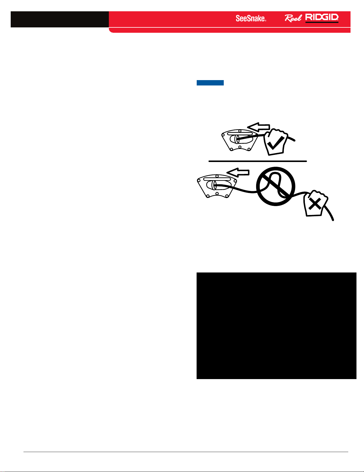
The nanoReel is equipped with a Sonde, built into the
camera head, which transmits a locatable 512 Hz signal,
allowing you to detect the camera’s location underground�
Controlling the Sonde from a SeeSnake CCU is
described in the operator’s manual for the CCU and
depends on the model being used� Typically, the Sonde
can be turned ON and OFF from the CCU� If using the
nanoReel with the micro CA‑300, activate the Sonde by
turning the LED brightness control down to zero� Once
the Sonde has been located, the LEDs can be returned
to normal brightness to continue the inspection�
When the nanoReel Sonde is turned ON, a locator such
as the RIDGID‑SeekTech SR‑20, RIDGID‑SeekTech
SR‑60, Scout, or NaviTrack® II set to 512 Hz can detect it�
To locate the camera using the Sonde, run the SeeSnake
push cable from 5 ft to 10 ft [1�5 m to 3 m] into the pipe
and use the locator to find the Sonde’s position� If desired,
extend the SeeSnake push cable from 5 ft to 10 ft [1�5 m
to 3 m] further down‑pipe and locate the Sonde again
starting from the previous located position� To locate the
Sonde, turn the locator ON and set it to Sonde mode�
Scan in the direction of the Sonde’s probable location
until the locator detects the Sonde�
Once you have detected the Sonde, use the locator
indications to zero in on its location precisely� For
detailed instructions on Sonde locating, consult the
operator’s manual for the locator model you are using�
during insertion� Do not force the push cable or exert
excessive force to avoid damaging the camera or push
cable� When pulling the push cable, keep clear of any
sharp edges and do not pull at sharp angles to the inlet
to prevent damage to the push cable�
NOTICE
lengths of the push cable back into the drum. Pushing back
longer lengths of push cable or forcing the push cable may
cause it to loop, kink and break (See Figure 21). Lay the
nanoReel drum on its back for more stability when retrieving the push cable.
Always use short strokes to feed back small
Figure 21 – Putting Back the Push Cable
Using Guide Tubes
Use guide tubes, such as PVC or flexible tubing, to avoid
marring or scratching porcelain surfaces (See Figure 22).
Figure 20 – Locating the nanoReel Sonde
Retrieving the Camera
After completing the inspection, pull the push cable back
with slow, steady force� If possible, continue running
water down the line to help clean the push cable� Use a
towel to wipe off the push cable as it is withdrawn�
Pay attention to the force required to withdraw the push
cable� The push cable may get hung up while being
retrieved and may need to be manipulated as done
Find Quality Products Online at: [email protected]
www.GlobalTestSupply.com
Figure 22 – Guide Tubes
Use PVC pipe and conduit to form a guide tube with a
curved access tube at the bottom to guide the push cable
past the porcelain without damage (See Figure23).
English – 13
Page 14

nano
TM
Figure 23 – Using a PVC Guide Tube
Use ribbed flexible conduit to fashion a flexible guide
tube similar to the PVC guide tube (See Figure 24)
�
Use a soft, damp cloth to wipe the nanoReel clean� Do
not use any solvents to clean the nanoReel� If desired,
use a disinfectant to clean the nanoReel�
The drum and cable may be removed and the interior
of the drum may be washed off with a hose or pressure
wash� Avoid hosing the contact board on the back of the
drum�
Accessories
WARNING
The following RIDGID products have been designed
to function with the nanoReel. Other accessories
suitable for use with other tools may become haz‑
ardous when used with the nanoReel. To reduce
the risk of serious injury, only use accessories spe‑
cically designed and recommended for use with
the nanoReel.
• nanoReel SlipRing Cartridge (Interconnect for
SeeSnake)
Figure 24 – Using the Flexible Guide Tube
Cleaning
WARNING
Maintain equipment in accordance with these pro‑
cedures to reduce the risk of serious injury and
damage to the machine.
Disconnect the system cable from the CCU before
cleaning to reduce the risk of electrical shock.
Clean the micro CA‑300 or CCU in accordance with
its operator’s manual� Before cleaning the nanoReel,
remove the micro CA‑300 from the display cradle� Do
not allow the micro CA‑300 or CCU to get wet during
cleaning�
• nanoReel SlipRing Cartridge (Interconnect for
micro CA‑300)
• RIDGID‑SeekTech or NaviTrack Locators
• RIDGID‑SeekTech or NaviTrack Transmitters
• RIDGID SeeSnake Camera Control Units
• RIDGID micro CA‑300
• nanoReel Ball Guides
• nanoReel Camera Head Guides
Transport and Storage
Keep the equipment indoors or well‑covered in wet
weather� Store the machine in a locked area, out of the
reach of children and people unfamiliar with its operation�
This machine could cause serious injury in the hands
of untrained users� Do not expose to heavy shocks or
impacts during transport�
Store electrical devices in a dry place to reduce the risk
of electrical shock� Store in temperatures from −4°F to
158°F [−20°C to 70°C]� Store the unit away from heat
sources such as radiators, heat registers, stoves, and
other products (including amplifiers) that produce heat�
14 – English
Find Quality Products Online at: [email protected]
www.GlobalTestSupply.com
Page 15
nano
TM
Service and Repair
WARNING
Improper service or repair can make the nanoReel
unsafe to operate.
Service
performed at a RIDGID Independent Authorized Service
Center�
For information on your nearest RIDGID
Independent Service Center or any service or repair
questions.
and repair of the SeeSnake nanoReel must be
Disposal
Parts of the nanoReel contain valuable materials that
can be recycled� Companies that specialize in recycling
may be found locally� Dispose of the components in
compliance with all applicable regulations� Contact your
local waste management authority for more information�
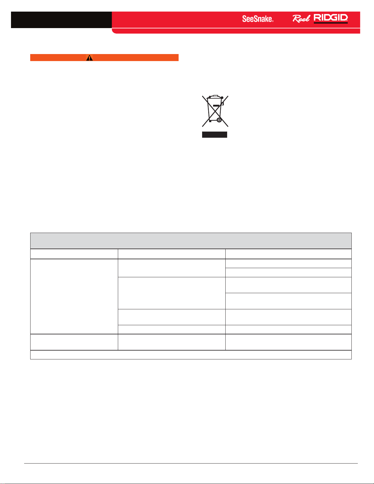
For EC Countries: Do not dispose of
electrical equipment with household waste!
According to the European Guideline
2002/96/EC for Waste Electrical and
Electronic Equipment and its implementation
into national legislation, electrical equipment
that is no longer usable must be collected separately
and disposed of in an environmentally correct manner�
Table 3
Troubleshooting
Problem Probable Fault Location Solution
No power to SeeSnake CCU or
micro
CA‑300 camera monitor connector
Camera image not seen
“SOS” code blinking on LCD* No video signal
* The light on the LCD will only blink the “SOS” code on some SeeSnake CCUs�
Connections faulty
Monitor set to wrong source
Batteries low Recharge or replace batteries�
Check power cord is correctly plugged in
Check the switch on monitor/display unit
Check alignment and pins of connection to the
nanoReel system unit from CCU or display unit�
Check orientation, seating, and pin condition in
Set video source as described in display unit
the SeeSnake connection�
operator’s manual�
Check source setting of monitor and
re seat cable connection�
English – 15
Find Quality Products Online at: [email protected]
www.GlobalTestSupply.com
Page 16

RIDGID reserves the right to change the specifications of the hardware, software, or both as described in this manual without notice. Due to product development, the
photos
Other trademarks or registered trademarks mentioned in this manual are the property of their respective owners.
and
other
presentations specified in this manual may differ from the actual product.
Printed in U.S.A.
EMERSON. CONSIDER IT SOLVED.
© 2011 RIDGID, Inc.
Find Quality Products Online at: [email protected]
www.GlobalTestSupply.com
TM
10/16/2015
744-034-539-EN-0A Rev A
 Loading...