

Page 1
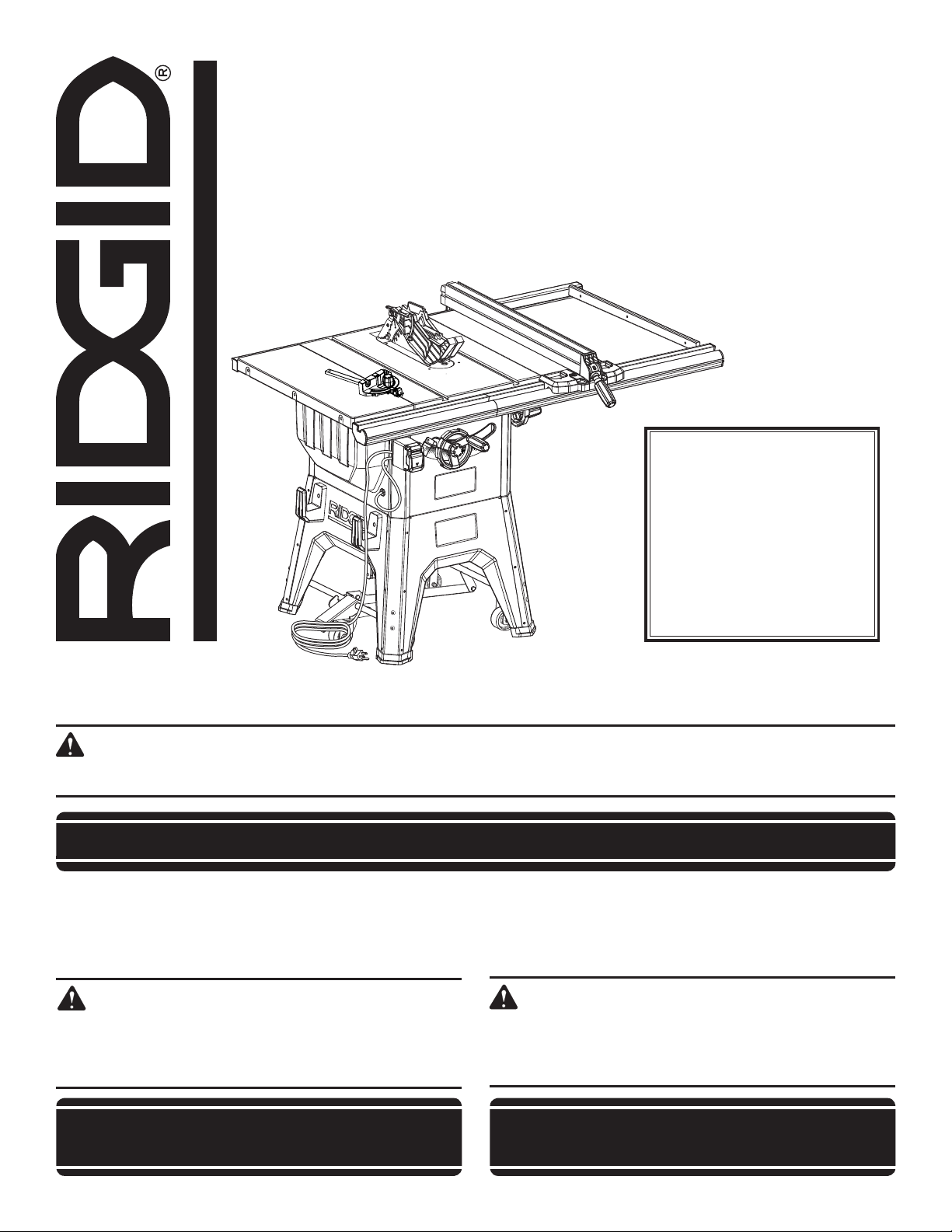
OPERATOR’S MANUAL
MANUEL D’UTILISATION
MANUAL DEL OPERADOR
10 in. TABLE SAW
SCIE À TABLE de 254 mm (10 po)
SIERRA DE MESA de 254 mm (10 pulg.)
R4512
45
Your saw has been engineered and manufactured to our high standard for dependability, ease of operation, and operator
safety. When properly cared for, it will give you years of rugged, trouble-free performance.
WARNING:
To reduce the risk of injury, the user must read and understand the operator’s manual before using this product.
SAVE THIS MANUAL FOR FUTURE REFERENCE
Cette scie a été conçue et fabriquée conformément aux strictes
normes de fiabilité, simplicité d’emploi et sécurité d’utilisation.
Correctement entretenu, cet outil vous donnera des années de
fonctionnement robuste et sans problème.
AVERTISSEMENT :
Pour réduire les risques de blessures, l’utilisateur
doit lire et veiller à bien comprendre le manuel
d’utilisation avant d’employer ce produit.
CONSERVER CE MANUEL POUR
Su sierra ha sido diseñado y fabricado de conformidad con
nuestras estrictas normas para brindar fiabilidad, facilidad de
uso y seguridad para el operador. Con el debido cuidado, le
brindará muchos años de sólido funcionamiento y sin problemas.
ADVERTENCIA:
Para reducir el riesgo de lesiones, el usuario debe
leer y comprender el manual del operador antes de
usar este producto.
GUARDE ESTE MANUAL PARA
FUTURE RÉFÉRENCE
Find Quality Products Online at: [email protected]
www.GlobalTestSupply.com
FUTURAS CONSULTAS
Page 2

TABLE OF CONTENTS
TABLE DES MATIÈRES / ÌNDICE DE CONTENIDO
Introduction ......................................................................................................................................................................2
Introduction / Introducción
General Safety Rules ..................................................................................................................................................... 3-4
Règles de sécurité générales / Reglas de seguridad generales
Table Saw Safety Rules .................................................................................................................................................4-6
Règles de sécurité scie à table / Reglas de seguridad sierra de mesa
Additional Safety Rules .................................................................................................................................................... 6
Règles de sécurité supplémentaires / Advertencias de seguridad adicionales
Symbols ............................................................................................................................................................................ 7
Symboles / Símbolos
Electrical
Caractéristiques électriques / Aspectos eléctricos
Glossary of Terms ........................................................................................................................................................... 10
Glossaire / Glosario de términos
Features .....................................................................................................................................................................11-13
Caractéristiques / Características
Tools Needed .................................................................................................................................................................. 14
Outils nécessaires / Herramientas necesarias
Loose Parts ...............................................................................................................................................................15-16
Pièces détachées / Piezas sueltas
Assembly ...................................................................................................................................................................17-28
Assemblage / Armado
Operation ...................................................................................................................................................................29-45
Utilisation / Funcionamiento
Adjustments ...............................................................................................................................................................46-49
Réglages / Ajustes
Maintenance ..............................................................................................................................................................50-51
Entretien / Mantenimiento
Accessories .................................................................................................................................................................... 51
Accessoires / Accesorios
Troubleshooting .........................................................................................................................................................52-53
Dépannage / Solución de problemas
Warranty .........................................................................................................................................................................54
Garantie / Garantía
Parts Ordering and Service ...............................................................................................................................Back page
Commande de pièces et réparation / Pedidos de piezas y servicio
........................................................................................................................................................................8-9
INTRODUCTION
INTRODUCTION / INTRODUCCIÓN
This product has many features for making its use more pleasant and enjoyable. Safety, performance, and dependability
have been given top priority in the design of this product making it easy to maintain and operate.
* * *
Ce produit offre de nombreuses fonctions destinées à rendre son utilisation plus plaisante et satisfaisante. Lors de la
conception de ce produit, l’accent a été mis sur la sécurité, les performances et la fiabilité, afin d’en faire un outil facile à
utiliser et à entretenir.
* * *
Este producto ofrece numerosas características para hacer más agradable y placentero su uso. En el diseño de este producto
se ha conferido prioridad a la seguridad, el desempeño y la fiabilidad, por lo cual se facilita su manejo y mantenimiento.
2
Find Quality Products Online at: [email protected]
www.GlobalTestSupply.com
Page 3

GENERAL SAFETY RULES
WARNING:
Read all safety warnings, instructions,
illustrations and specifications provided with
this power tool. Failure to follow all instructions
listed below may result in electric shock, fire and/
or serious injury.
Save all warnings and instructions for future reference.
The term “power tool” in the warnings refers to your mainsoperated (corded) power tool or battery-operated (cordless)
power tool.
WORK AREA SAFETY
Keep work area clean and well lit. Cluttered or dark
areas invite accidents.
Do not operate power tools in explosive atmospheres,
such as in the presence of flammable liquids, gases
or dust. Power tools create sparks which may ignite the
dust or fumes.
Keep children and bystanders away while operating a
power tool. Distractions can cause you to lose control.
ELECTRICAL SAFETY
Power tool plugs must match the outlet. Never modify
the plug in any way. Do not use any adapter plugs with
earthed (grounded) power tools. Unmodified plugs and
matching outlets will reduce risk of electric shock.
Avoid body contact with earthed or grounded surfaces,
such as pipes, radiators, ranges and refrigerators.
There is an increased risk of electric shock if your body
is earthed or grounded.
Do not expose power tools to rain or wet conditions.
Water entering a power tool will increase the risk of electric
shock.
Do not abuse the cord. Never use the cord for carrying,
pulling or unplugging the power tool. Keep cord away
from heat, oil, sharp edges or moving parts. Damaged
or entangled cords increase the risk of electric shock.
When operating a power tool outdoors, use an
extension cord suitable for outdoor use. Use of a cord
suitable for outdoor use reduces the risk of electric shock.
If operating a power tool in a damp location is
unavoidable, use a ground fault circuit interrupter
(GFCI) protected supply. Use of a GFCI reduces the risk
of electric shock.
PERSONAL SAFETY
Stay alert, watch what you are doing and use common
sense when operating a power tool. Do not use a
power tool while you are tired or under the influence
of drugs, alcohol or medication. A moment of inattention
while operating power tools may result in serious personal
injury.
Use personal protective equipment. Always wear eye
protection. Protective equipment such as dust mask,
non-skid safety shoes, hard hat, or hearing protection used
for appropriate conditions will reduce personal injuries.
Prevent unintentional starting. Ensure the switch is in
the off-position before connecting to power source
and/or battery pack, picking up or carrying the tool.
Carrying power tools with your finger on the switch or
energising power tools that have the switch on invites
accidents.
Remove any adjusting key or wrench before turning
the power tool on. A wrench or a key left attached to a
rotating part of the power tool may result in personal injury.
Do not overreach. Keep proper footing and balance
at all times. This enables better control of the power tool
in unexpected situations.
Dress properly. Do not wear loose clothing or jewellery.
Keep your hair, clothing and gloves away from moving
parts. Loose clothes, jewellery or long hair can be caught
in moving parts.
If devices are provided for the connection of dust
extraction and collection facilities, ensure these are
connected and properly used. Use of dust collection
can reduce dust-related hazards.
Do not let familiarity gained from frequent use of tools
allow you to become complacent and ignore tool safety
principles. A careless action can cause severe injury within
a fraction of a second.
POWER TOOL USE AND CARE
Do not force the power tool. Use the correct power
tool for your application. The correct power tool will
do the job better and safer at the rate for which it was
designed.
Do not use the power tool if the switch does not turn
it on and off. Any power tool that cannot be controlled
with the switch is dangerous and must be repaired.
Disconnect the plug from the power source and/
or remove the battery pack, if detachable, from the
power tool before making any adjustments, changing
accessories, or storing power tools. Such preventive
safety measures reduce the risk of starting the power tool
accidentally.
3 - English
Find Quality Products Online at: [email protected]
www.GlobalTestSupply.com
Page 4

GENERAL SAFETY RULES
Store idle power tools out of the reach of children and
do not allow persons unfamiliar with the power tool
or these instructions to operate the power tool. Power
tools are dangerous in the hands of untrained users.
Maintain power tools and accessories. Check for
misalignment or binding of moving parts, breakage
of parts and any other condition that may affect the
power tool’s operation. If damaged, have the power
tool repaired before use. Many accidents are caused
by poorly maintained power tools.
Keep cutting tools sharp and clean. Properly maintained
cutting tools with sharp cutting edges are less likely to
bind and are easier to control.
Use the power tool, accessories and tool bits etc.
in accordance with these instructions, taking into
TABLE SAW SAFETY RULES
BLADE GUARD, RIVING KNIFE AND ANTIKICKBACK PAWLS
Keep guards in place. Guards must be in working
order and be properly mounted. A guard that is loose,
damaged, or is not functioning correctly must be repaired
or replaced.
Always use saw blade guard, riving knife and anti-
kickback pawls for every through-cutting operation.
For through-cutting operations where the saw blade cuts
completely through the thickness of the workpiece, the
guard and other safety devices help reduce the risk of
injury.
Immediately reattach the guarding system after
completing an operation (such as rabbeting, dadoing
or resawing cuts) which requires removal of the guard,
riving knife and/or anti-kickback pawls. The guard,
riving knife, and anti-kickback pawls help to reduce the
risk of injury.
Make sure the saw blade is not contacting the guard,
riving knife or the workpiece before the switch is
turned on. Inadvertent contact of these items with the
saw blade could cause a hazardous condition.
Adjust the riving knife as described in the operator’s
manual. Incorrect spacing, positioning and alignment can
make the riving knife ineffective in reducing the likelihood
of kickback.
For the riving knife and anti-kickback pawls to work,
they must be engaged in the workpiece. The riving
knife and anti-kickback pawls are ineffective when cutting
workpieces that are too short to be engaged with the riving
knife and anti-kickback pawls. Under these conditions
a kickback cannot be prevented by the riving knife and
anti-kickback pawls.
account the working conditions and the work to be
performed. Use of the power tool for operations different
from those intended could result in a hazardous situation.
Keep handles and grasping surfaces dry, clean and
free from oil and grease. Slippery handles and grasping
surfaces do not allow for safe handling and control of the
tool in unexpected situations.
SERVICE
Have your power tool serviced by a qualified repair
person using only identical replacement parts. This will
ensure that the safety of the power tool is maintained.
Use the appropriate saw blade for the riving knife.
For the riving knife to function properly, the saw blade
diameter must match the appropriate riving knife and the
body of the saw blade must be thinner than the thickness
of the riving knife and the cutting width of the saw blade
must be wider than the thickness of the riving knife.
CUTTING PROCEDURES
DANGER: Never place your fingers or hands in the
vicinity or in line with the saw blade. A moment of
inattention or a slip could direct your hand towards the
saw blade and result in serious personal injury.
Feed the workpiece into the saw blade against the
direction of rotation. Feeding the workpiece in the same
direction that the saw blade is rotating above the table
may result in the workpiece, and your hand, being pulled
into the saw blade.
Never use the miter gauge to feed the workpiece when
ripping and do not use the rip fence as a length stop
when cross cutting with the miter gauge. Guiding the
workpiece with the rip fence and the miter gauge at the
same time increases the likelihood of saw blade binding
and kickback.
When ripping, always apply the workpiece feeding
force between the fence and the saw blade. Use a
push stick when the distance between the fence and
the saw blade is less than 150 mm, and use a push
block when this distance is less than 50 mm. “Work
helping” devices will keep your hand at a safe distance
from the saw blade.
Use only the push stick provided by the manufacturer
or constructed in accordance with the instructions.
This push stick provides sufficient distance of the hand
from the saw blade.
4 - English
Find Quality Products Online at: [email protected]
www.GlobalTestSupply.com
Page 5

TABLE SAW SAFETY RULES
Never use a damaged or cut push stick. A damaged
push stick may break causing your hand to slip into the
saw blade.
Do not perform any operation “freehand”. Always
use either the rip fence or the miter gauge to position
and guide the workpiece. “Freehand” means using
your hands to support or guide the workpiece, in lieu
of a rip fence or miter gauge. Freehand sawing leads to
misalignment, binding and kickback.
Never reach around or over a rotating saw blade.
Reaching for a workpiece may lead to accidental contact
with the moving saw blade.
Provide auxiliary workpiece support to the rear and/or
sides of the saw table for long and/or wide workpieces
to keep them level. A long and/or wide workpiece has
a tendency to pivot on the table’s edge, causing loss of
control, saw blade binding and kickback.
Feed workpiece at an even pace. Do not bend or
twist the workpiece. If jamming occurs, turn the tool
off immediately, unplug the tool then clear the jam.
Jamming the saw blade by the workpiece can cause
kickback or stall the motor.
Do not remove pieces of cut-off material while the saw
is running. The material may become trapped between
the fence or inside the saw blade guard and the saw
blade pulling your fingers into the saw blade. Turn the saw
off and wait until the saw blade stops before removing
material.
Use an auxiliary fence in contact with the table top
when ripping workpieces less than 2 mm thick. A thin
workpiece may wedge under the rip fence and create a
kickback.
KICKBACK
Kickback is a sudden reaction of the workpiece due to a
pinched, jammed saw blade or misaligned line of cut in the
workpiece with respect to the saw blade or when a part of
the workpiece binds between the saw blade and the rip
fence or other fixed object.
Most frequently during kickback, the workpiece is lifted from
the table by the rear portion of the saw blade and is propelled
towards the operator.
Kickback is the result of saw misuse and/or incorrect
operating procedures or conditions and can be avoided by
taking proper precautions as given below.
Never stand directly in line with the saw blade. Always
position your body on the same side of the saw blade
as the fence. Kickback may propel the workpiece at high
velocity towards anyone standing in front and in line with
the saw blade.
Never reach over or in back of the saw blade to pull or
to support the workpiece. Accidental contact with the
saw blade may occur or kickback may drag your fingers
into the saw blade.
Never hold and press the workpiece that is being
cut off against the rotating saw blade. Pressing the
workpiece being cut off against the saw blade will create
a binding condition and kickback.
Align the fence to be parallel with the saw blade. A
misaligned fence will pinch the workpiece against the
saw blade and create kickback.
Use a featherboard to guide the workpiece against the
table and fence when making non-through cuts such
as rabbeting, dadoing or resawing cuts. A featherboard
helps to control the workpiece in the event of a kickback.
Use extra caution when making a cut into blind areas
of assembled workpieces. The protruding saw blade
may cut objects that can cause kickback.
Support large panels to minimize the risk of saw blade
pinching and kickback. Large panels tend to sag under
their own weight. Support(s) must be placed under all
portions of the panel overhanging the table top.
Use extra caution when cutting a workpiece that is
twisted, knotted, warped or does not have a straight
edge to guide it with a miter gauge or along the fence.
A warped, knotted, or twisted workpiece is unstable
and causes misalignment of the kerf with the saw blade,
binding and kickback.
Never cut more than one workpiece, stacked vertically
or horizontally. The saw blade could pick up one or more
pieces and cause kickback.
When restarting the saw with the saw blade in the
workpiece, centre the saw blade in the kerf so that
the saw teeth are not engaged in the material. If the
saw blade binds, it may lift up the workpiece and cause
kickback when the saw is restarted.
Keep saw blades clean, sharp, and with sufficient
set. Never use warped saw blades or saw blades with
cracked or broken teeth. Sharp and properly set saw
blades minimise binding, stalling and kickback.
TABLE SAW OPERATION
Turn off the table saw and disconnect the power
cord when removing the throat plate, changing the
saw blade or making adjustments to the riving knife,
anti-kickback pawls or blade guard, and when the
machine is left unattended. Precautionary measures
will avoid accidents.
Never leave the table saw running unattended. Turn it
off and don’t leave the tool until it comes to a complete
stop. An unattended running saw is an uncontrolled
hazard.
Locate the table saw in a well-lit and level area where
you can maintain good footing and balance. It should
be installed in an area that provides enough room to
easily handle the size of your workpiece. Cramped,
dark areas, and uneven slippery floors invite accidents.
5 - English
Find Quality Products Online at: [email protected]
www.GlobalTestSupply.com
Page 6

TABLE SAW SAFETY RULES
Frequently clean and remove sawdust from under
the saw table and/or the dust collection device.
Accumulated sawdust is combustible and may self-ignite.
The table saw must be secured. A table saw that is not
properly secured may move or tip over.
Remove tools, wood scraps, etc. from the table before
the table saw is turned on. Distraction or a potential jam
can be dangerous.
Always use saw blades with correct size and shape
(diamond versus round) of arbour holes. Saw blades
that do not match the mounting hardware of the saw will
run off-centre, causing loss of control.
ADDITIONAL SAFETY RULES
Know your power tool. Read the operator’s manual
carefully. Learn the saw’s applications and limitations as
well as the specific potential hazards related to this tool.
Make workshop childproof with padlocks and master
switches, or by removing starter keys.
Use the proper extension cord. Make sure your extension
cord is in good condition. Use only a cord heavy enough
to carry the current your product will draw. An undersized
cord will cause a drop in line voltage resulting in loss of
power and overheating. A wire gauge size (A.W.G.) of at
least 14 is recommended for an extension cord 25 feet
or less in length. If in doubt, use the next heavier gauge.
The smaller the gauge number, the heavier the cord.
Always wear eye protection with side shields marked
to comply with ANSI Z87.1. Failure to do so could result
in objects being thrown into your eyes, resulting in possible
serious injury.
Secure work. Use clamps or a vise to hold work when
practical. It’s safer than using your hand and frees both
hands to operate tool.
Use recommended accessories. Consult the operator’s
manual for recommended accessories. The use of
improper accessories may risk injury.
Use only correct blades. Do not use blades with incorrect
size holes. Never use blade washers or blade bolts that
are defective or incorrect. The maximum blade capacity
of your saw is 10 in. (254 mm).
Never use damaged or incorrect saw blade mounting
means such as flanges, saw blade washers, bolts or
nuts. These mounting means were specially designed for
your saw, for safe operation and optimum performance.
Never stand on the table saw, do not use it as a
stepping stool. Serious injury could occur if the tool is
tipped or if the cutting tool is accidentally contacted.
Make sure that the saw blade is installed to rotate
in the proper direction. Do not use grinding wheels,
wire brushes, or abrasive wheels on a table saw.
Improper saw blade installation or use of accessories
not recommended may cause serious injury.
Check damaged parts. Before further use of the tool, a
guard or other part that is damaged should be carefully
checked to determine that it will operate properly and
perform its intended function. Check for alignment of
moving parts, binding of moving parts, breakage of parts,
mounting and any other conditions that may affect its
operation. A guard or other part that is damaged must
be properly repaired or replaced by an authorized service
center to avoid risk of personal injury.
Never leave tool running unattended. Turn the power
off. Don’t leave tool until it comes to a complete stop.
Protect your lungs. Wear a face or dust mask if the
cutting operation is dusty.
Protect your hearing. Wear hearing protection during
extended periods of operation.
When operating a power tool outside, use an outdoor
extension cord marked “W-A” or “W”. These cords
are rated for outdoor use and reduce the risk of electric
shock.
Always keep the blade guard and riving knife (splitter)
in place and in working order.
Keep hands away from cutting area. Keep hands away
from blades. Do not reach underneath work or around or
over the blade while blade is rotating. Do not attempt to
remove cut material when blade is moving.
6 - English
Find Quality Products Online at: [email protected]
www.GlobalTestSupply.com
Page 7
SYMBOLS
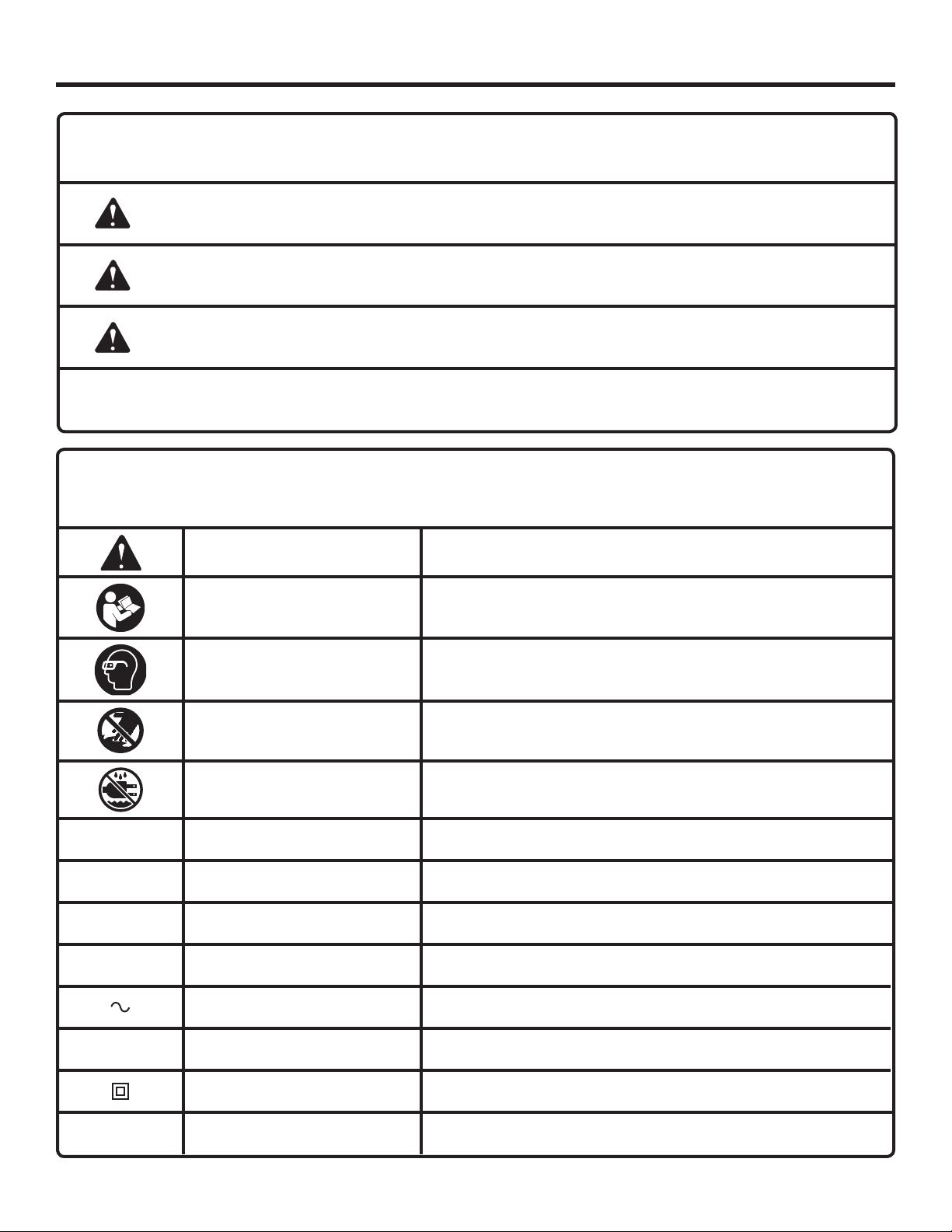
The following signal words and meanings are intended to explain the levels of risk associated with this product.
SYMBOL SIGNAL MEANING
DANGER:
WARNING:
CAUTION:
NOTICE:
Some of the following symbols may be used on this tool. Please study them and learn their meaning. Proper
interpretation of these symbols will allow you to operate the tool better and safer.
Indicates a hazardous situation, which, if not avoided, will result in death or
serious injury.
Indicates a hazardous situation, which, if not avoided, could result in death or
serious injury.
Indicates a hazardous situation, that, if not avoided, may result in minor or
moderate injury.
(Without Safety Alert Symbol) Indicates information considered important, but
not related to a potential injury (e.g. messages relating to property damage).
SYMBOL NAME DESIGNATION/EXPLANATION
Safety Alert Indicates a potential personal injury hazard.
Read Operator’s Manual
To reduce the risk of injury, user must read and understand
operator’s manual before using this product.
Eye Protection
No Hands Symbol
Wet Conditions Alert Do not expose to rain or use in damp locations.
V Volts Voltage
A Amperes Current
Hz Hertz Frequency (cycles per second)
min Minutes Time
Alternating Current Type of current
n
o
No Load Speed Rotational speed, at no load
Class II Construction Double-insulated construction
Always wear eye protection with side shields marked to comply
with ANSI Z87.1.
Failure to keep your hands away from the blade will result in
serious personal injury.
.../min Per Minute Revolutions, strokes, surface speed, orbits, etc., per minute
7 - English
Find Quality Products Online at: [email protected]
www.GlobalTestSupply.com
Page 8
ELECTRICAL
EXTENSION CORDS
Use only 3-wire extension cords that have 3-prong grounding
plugs and 3-pole receptacles that accept the tool's plug.
When using a power tool at a considerable distance from
the power source, use an extension cord heavy enough
to carry the current that the tool will draw. An undersized
extension cord will cause a drop in line voltage, resulting in
a loss of power and causing the motor to overheat. Use the
chart provided below to determine the minimum wire size
required in an extension cord. Only round jacketed cords
listed by Underwriter's Laboratories (UL) should be used.
**Ampere rating (on tool faceplate)
0-2.0 2.1-3.4 3.5-5.0 5.1-7.0 7.1-12.0 12.1-16.0
Cord Length Wire Size (A.W.G.)
25' 16 16 16 16 14 14
50' 16 16 16 14 14 12
100' 16 16 14 12 10 —
**Used on 12 gauge - 20 amp circuit.
NOTE: AWG = American Wire Gauge
When working with the tool outdoors, use an extension cord
that is designed for outside use. This is indicated by the
letters “W-A” or “W” on the cord’s jacket.
Before using an extension cord, inspect it for loose or
exposed wires and cut or worn insulation.
WARNING:
Keep the extension cord clear of the working
area. Position the cord so that it will not get
caught on lumber, tools or other obstructions
while you are working with a power tool. Failure
to do so can result in serious personal injury.
WARNING:
Check extension cords before each use. If
damaged replace immediately. Never use
product with a damaged cord since touching
the damaged area could cause electrical shock
resulting in serious injury.
SPEED AND WIRING
The no-load speed of this tool is approximately 3,450 rpm.
This speed is not constant and decreases under a load or
with lower voltage. For voltage, the wiring in a shop is as
important as the motor’s horsepower rating. A line intended
only for lights cannot properly carry a power tool motor. Wire
that is heavy enough for a short distance will be too light for
a greater distance. A line that can support one power tool
may not be able to support two or three tools.
GROUNDING INSTRUCTIONS
This product must be grounded. In the event of a malfunction
or breakdown, grounding provides a path of least resistance
for electric current to reduce the risk of electric shock. This
tool is equipped with an electric cord having an equipmentgrounding conductor and a grounding plug. The plug must be
plugged into a matching outlet that is properly installed and
grounded in accordance with all local codes and ordinances.
Do not modify the plug provided. If it will not fit the outlet,
have the proper outlet installed by a qualified electrician.
WARNING:
Improper connection of the grounding plug can
result in a risk of electric shock. When repair
or replacement of the cord is required, do not
connect the grounding wire to either flat blade
terminal. The wire with insulation having an
outer surface that is green with or without yellow
stripes is the grounding wire.
Check with a qualified electrician or service personnel if the
grounding instructions are not completely understood, or if
in doubt as to whether the tool is properly grounded.
Repair or replace a damaged or worn cord immediately.
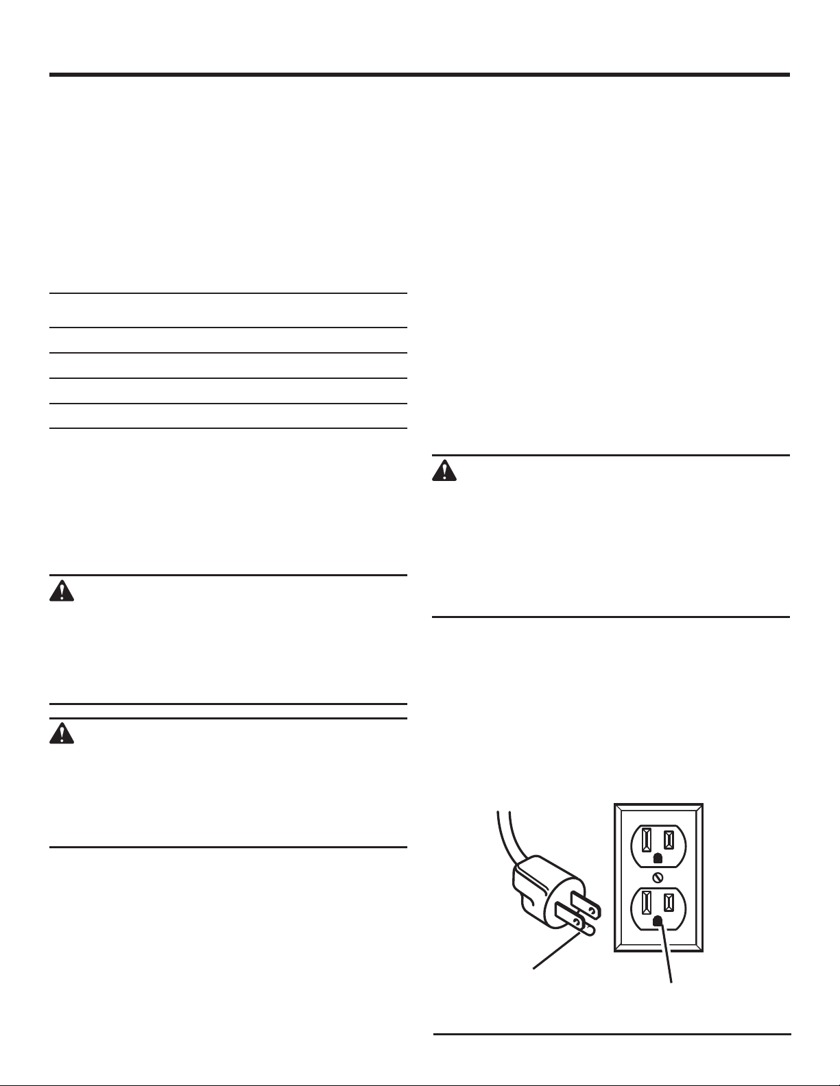
This product is for use on a nominal 120 volt circuit and has
a grounding plug similar to the plug illustrated in figure 1.
Only connect the product to an outlet having the same
configuration as the plug. Do not use an adapter with this
product.
ELECTRICAL CONNECTION
This product is powered by a precision built electric motor.
It should be connected to a power supply that is 120 V, AC
only (normal household current), 60 Hz. Do not operate
this product on direct current (DC). A substantial voltage
drop will cause a loss of power and the motor will overheat.
If the saw does not operate when plugged into an outlet,
double check the power supply.
8 - English
Find Quality Products Online at: [email protected]
www.GlobalTestSupply.com
GROUNDING
PIN
120 V GROUNDED
OUTLET
Fig. 1
Page 9
ELECTRICAL
WARNING:
To prevent possible electrical hazards, have a
qualified electrician check the line if you are not
certain that it is properly wired.
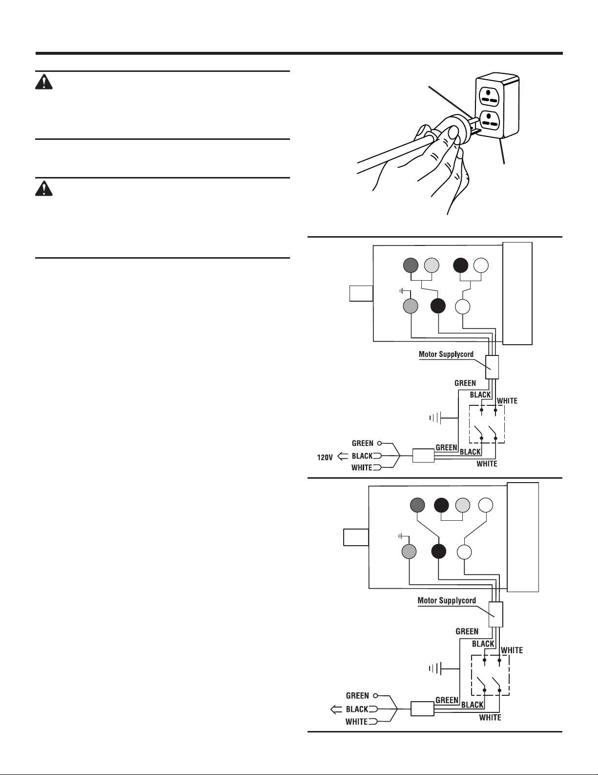
CHANGING MOTOR VOLTAGE
See Figures 2 - 4.
WARNING:
Electric shock can kill. To reduce the risk of
serious personal injury, never connect plug
to power source until all assembly steps are
completed.
NOTE: The table saw is prewired at the factory for 120 V,
60 Hz. Use the following procedures to change motor voltage
from 120 V to 240 V. This is an optional procedure to be
completed after the saw has been fully assembled.
Unplug the saw.
Remove the 6 screws that secure the rear panel of the
saw. Remove the panel.
Lower the motor to its lowest point.
Located on the top of the motor is the junction box.
Remove the phillips screw at the back of the junction
box then lift off the cover.
Remove and discard the electrical tape from the wire
connectors. Remove wire connectors.
Reconnect the leads.
Reinstall the wire connectors and wrap each wire with
two layers of new UL listed electrical tape.
Recheck your wiring with the wiring diagrams.
Reinstall the junction box cover using the phillips screw.
Cut off the 120 volt power cord plug and replace it with
a 3-prong 240 volt, 15 amp. UL listed plug.
Connect the power cord white and black leads,
respectively, to the “hot” plug blade terminals. Connect
the power cord green grounding wire to the plug ground
prong terminal.
Reinstall the rear panel.
Plug your table saw into a 220-240 V, 15 amp., 3-prong
receptacle. Make certain the receptacle is connected to
a 240 V, AC power supply through a 240 V branch circuit
having at least a 15 amp capacity and protected by a
15 amp time-delay fuse or circuit breaker.
GROUNDING
PIN
COVER OF
GROUNDED
OUTLET BOX
FOR USE WITH 220-240 VOLT
YELLOW
RED BLACK
3
1
G
L1
BLACK
WHITEGREEN
RED BLACK
2 3
1
L1
G
BLACK WHITEGREEN
2
L2
YELLOW
L2
WHITE
4
WHITE
4
Fig. 2
Fig. 3
240V
Fig. 4
9 - English
Find Quality Products Online at: [email protected]
www.GlobalTestSupply.com
Page 10

GLOSSARY OF TERMS
Anti-Kickback Pawls (radial arm and table saws)
A device which, when properly installed and maintained,
is designed to stop the workpiece from being kicked back
toward the front of the saw during a ripping operation.
Arbor
The shaft on which a blade or cutting tool is mounted.
Bevel Cut
A cutting operation made with the blade at any angle other
than 90° to the table surface.
Chamfer
A cut removing a wedge from a block so the end (or part of
the end) is angled rather than at 90°.
Compound Cut
A cross cut made with both a miter and a bevel angle.
Cross Cut
A cutting or shaping operation made across the grain or the
width of the workpiece.
Cutter Head (planers and jointer planers)
A rotating cutterhead with adjustable blades or knives. The
blades or knives remove material from the workpiece.
Dado Cut (table saws and compound sliding miter saws)
A non-through cut which produces a square, three-sided
notch or trough in the workpiece.
Featherboard (table saws)
A device used to help control the workpiece by guiding
it securely against the table or fence during any ripping
operation.
FPM or SPM
Feet per minute (or strokes per minute), used in reference
to blade movement.
Freehand
Performing a cut without the workpiece being guided by a
fence, miter fence, or other aids.
Gum
A sticky, sap-based residue from wood products.
Heel
Alignment of the blade to the miter gauge groove.
Kerf
The material removed by the blade in a through cut or the
slot produced by the blade in a non-through or partial cut.
Kickback
A hazard that can occur when the blade binds or stalls,
throwing the workpiece in the direction of the spinning blade.
Miter Cut
A cutting operation made with the workpiece at any angle
to the blade other than 90°.
Non-Through Cuts (table saws and compound sliding
miter saws)
Any cutting operation where the blade does not extend
completely through the thickness of the workpiece. This is a
cut where the blade will not cut the workpiece into two pieces.
10 - English
Find Quality Products Online at: [email protected]
www.GlobalTestSupply.com
Pilot Hole (drill presses and scroll saws)
A small hole drilled in a workpiece that serves as a guide
for drilling large holes accurately or for insertion of a scroll
saw blade.
Push Blocks (jointer planers)
Device used to feed the workpiece over the jointer planer
cutterhead during any operation. This aid helps keep the
operator’s hands well away from the cutterhead.
Push Blocks and Push Sticks (table saws)
Devices used to feed the workpiece through the saw blade
during cutting operations. When making a narrow rip cut
without a jig or similar cutting aid, always use a push stick
(not a push block). A push block can be used for narrow
ripping operations, if a jig or similar cutting aid is used.
These aids help keep the operator’s hands well away from
the blade.
Rabbet
A non-through cut positioned on the end or edge of the
workpiece which produces a square, two-sided notch or
trough in the workpiece.
Resaw (table saws and band saws)
A cutting operation to reduce the thickness of the workpiece
to make thinner pieces.
Resin
A sticky, sap-based substance that has hardened.
Revolutions Per Minute (RPM)
The number of turns completed by a spinning object in one
minute.
Ripping or Rip Cut (table saws)
A cutting operation along the length of the workpiece and
typically in the direction of the grain.
Riving Knife/Spreader/Splitter (table saws)
A metal piece, slightly thinner than the blade, which helps
keep the kerf open and also helps to prevent kickback.
Saw Blade Path
The area over, under, behind, or in front of the blade. As it
applies to the workpiece, that area which will be or has been
cut by the blade.
Snipe (planers)
Depression made at either end of a workpiece by cutter
blades when the workpiece is not properly supported.
Taper Cut
A cut where the material being cut has a different width at
the beginning of the cut from the end.
Through Sawing
Any cutting operation where the blade extends completely
through the thickness of the workpiece. This type of cut will
separate a single workpiece into two pieces.
Workpiece or Material
The item on which the operation is being done.
Worktable
Surface where the workpiece rests while performing a
cutting, drilling, planing, or sanding operation.
Page 11
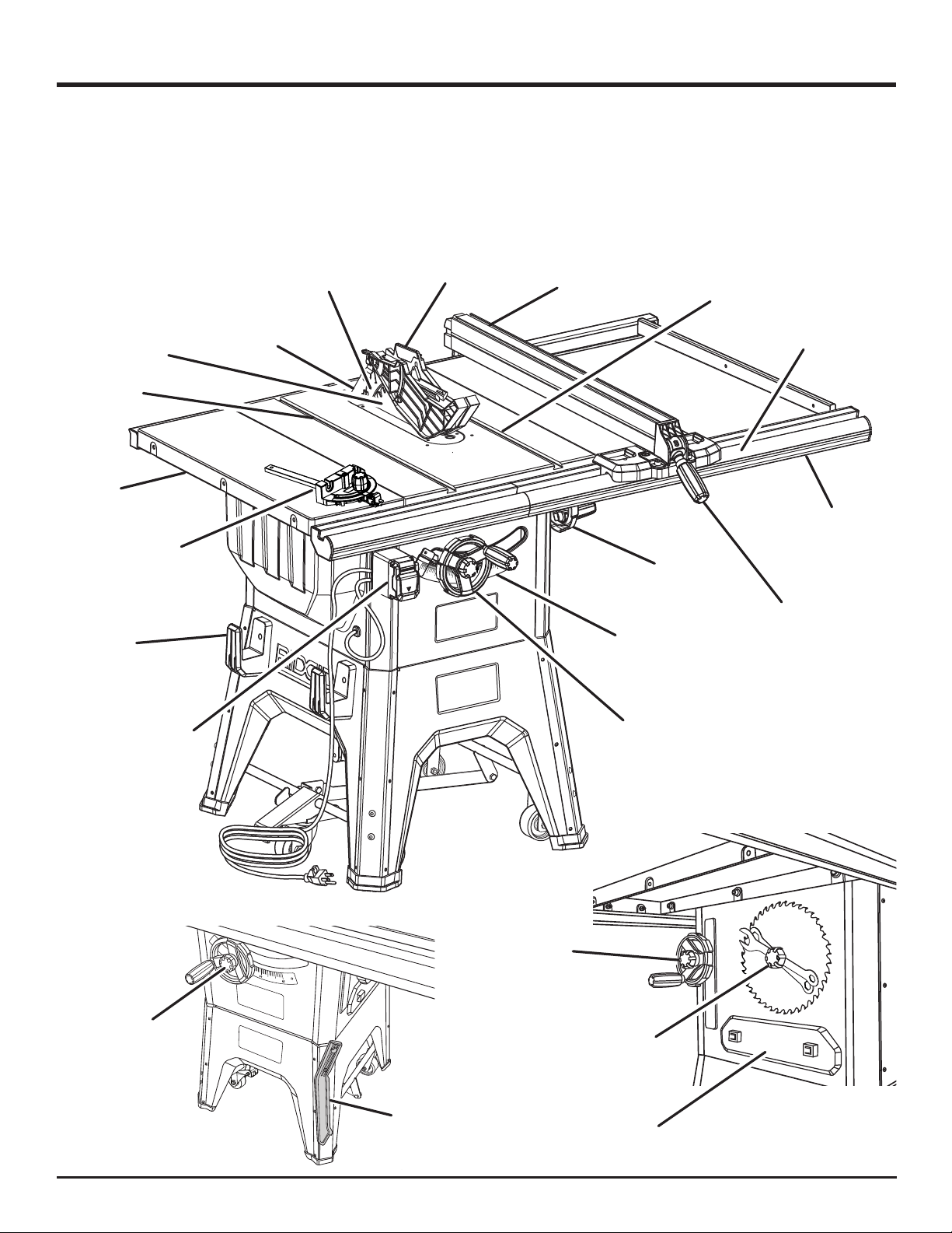
FEATURES
PRODUCT SPECIFICATIONS
Blade Arbor ...............................................................5/8 in.
Blade Diameter
Blade Tilt
Rating
............................ 120/240 V ~, 13/6.5 Amps, 60 Hz
........................................................... 10 in.
..................................................................0˚ - 45˚
No Load Speed
Cutting Depth at 0º:
Cutting Depth at 45º:
.....................................3,450 r/min. (RPM)
............................................... 3-1/4 in.
............................................. 2-1/4 in.
MITER
GAUGE
GROOVE
TABLE
EXTENSION
RIP FENCE
STORAGE
BRACKETS
SAW
BLADE
MITER
GAUGE
RIVING KNIFE
ANTI-KICKBACK
PAWLS
BLADE GUARD
ASSEMBLY
RIP
FENCE
45
ADJUSTING
HANDWHEEL
BEVEL
SCALE
MITER
GAUGE
GROOVE
RIP FENCE
SCALE
FRONT
RAIL
BEVEL
LOCKING
HANDLE
SWITCH
ASSEMBLY
HEIGHT
LOCK
KNOB
PUSH
STICK
HEIGHT
ADJUSTING
HANDWHEEL
BEVEL
LOCK KNOB
BLADE AND
WRENCH
STORAGE
MITER GAUGE
STORAGE
Fig. 5
11 - English
Find Quality Products Online at: [email protected]
www.GlobalTestSupply.com
Page 12
FEATURES
KNOW YOUR TABLE SAW
See Figure 5.
The safe use of this product requires an understanding of
the information on the tool and in this operator’s manual as
well as a knowledge of the project you are attempting. Before
use of this product, familiarize yourself with all operating
features and safety rules.
ANTI-KICKBACK PAWLS - Kickback is a hazard in which
the workpiece is thrown back toward the operator. The teeth
on the removable anti-kickback pawls point away from the
workpiece. If the workpiece should be pulled back toward
the operator, the teeth dig into the wood to help prevent or
reduce the possibility of kickback.
BEVEL ADJUSTING HANDWHEEL/BEVEL LOCK KNOB
The bevel adjusting handwheel, located on the side of the
cabinet, is used to adjust the bevel angle of the blade.The
bevel lock knob locks the angle setting of the blade.
BEVEL SCALE - The easy-to-read scale on the front of the
cabinet shows the exact blade angle.
BLADE - For maximum performance, it is recommended
that you use the 10 in. carbide tipped combination blade
provided with your saw. The blade is raised and lowered with
the height adjusting handwheel. Bevel angles are locked with
the bevel lock knob. Additional blade styles of the same high
quality are available for specific operations such as ripping.
Your local dealer can provide you with complete information.
Blade kerf width must be within the limits stamped on the
riving knife.
-
WARNING:
Do not use blades rated less than the speed of
this tool. Failure to heed this warning could result
in personal injury.
BLADE GUARD - Always keep the removable blade guard
down over the saw blade for through-sawing cuts.
HEIGHT ADJUSTING HANDWHEEL/ HEIGHT LOCK
KNOB - The height adusting handwheel, located on the
front of the cabinet, is used to lower and raise the blade for
height adjustments or blade replacement. The height lock
knob locks the height setting of the blade.
MITER GAUGE - The miter gauge aligns the workpiece for
a cross cut. The easy-to-read indicator shows the exact
angle for a miter cut, with adjustable stops at 90° and 45°.
MITER GAUGE GROOVES - The miter gauge rides in the
grooves on the saw table.
RIP FENCE - A sturdy metal fence guides the workpiece and
is secured with the locking handle. Grooves run along the
top and sides of the rip fence for use with optional clamps
and accessories.
RIVING KNIFE - A removable metal piece of the blade
guard assembly, slightly thinner than the saw blade, which
helps keep the kerf open and prevent kickback. When in the
through sawing, or “up” position, it is higher than the saw
blade. When in the non-through sawing, or “down” position,
it is below the saw blade teeth.
RIP SCALE - Located on the front rail, the easy-to-read rip
scale provides precise measurements for rip cuts.
SWITCH ASSEMBLY - This saw has an easy access switch
assembly located below the front rail. To lock the switch in
the OFF position, remove the switch key from the switch.
Place the key in a location that is inaccessible to children
and others not qualified to use the tool.
TABLE EXTENSION - Located on each side of the saw table,
the table extensions give the operator additional support
when cutting wide workpieces.
12 - English
Find Quality Products Online at: [email protected]
www.GlobalTestSupply.com
Page 13
FEATURES
OPERATING COMPONENTS
The upper portion of the blade projects up through the table
and is surrounded by an insert called the throat plate. The
height of the blade is set with a handwheel on the front of the
cabinet. Detailed instructions are provided in the Operation
section of this manual for the basic cuts: cross cuts, miter
cuts, bevel cuts, and compound cuts.
The rip fence is used to position work for lengthwise cuts.
A scale on the front rail shows the distance between the rip
fence and the blade.
It is very important to use the blade guard assembly for
all through-sawing operations. The blade guard assembly
includes: riving knife, anti-kickback pawls, and blade guard.
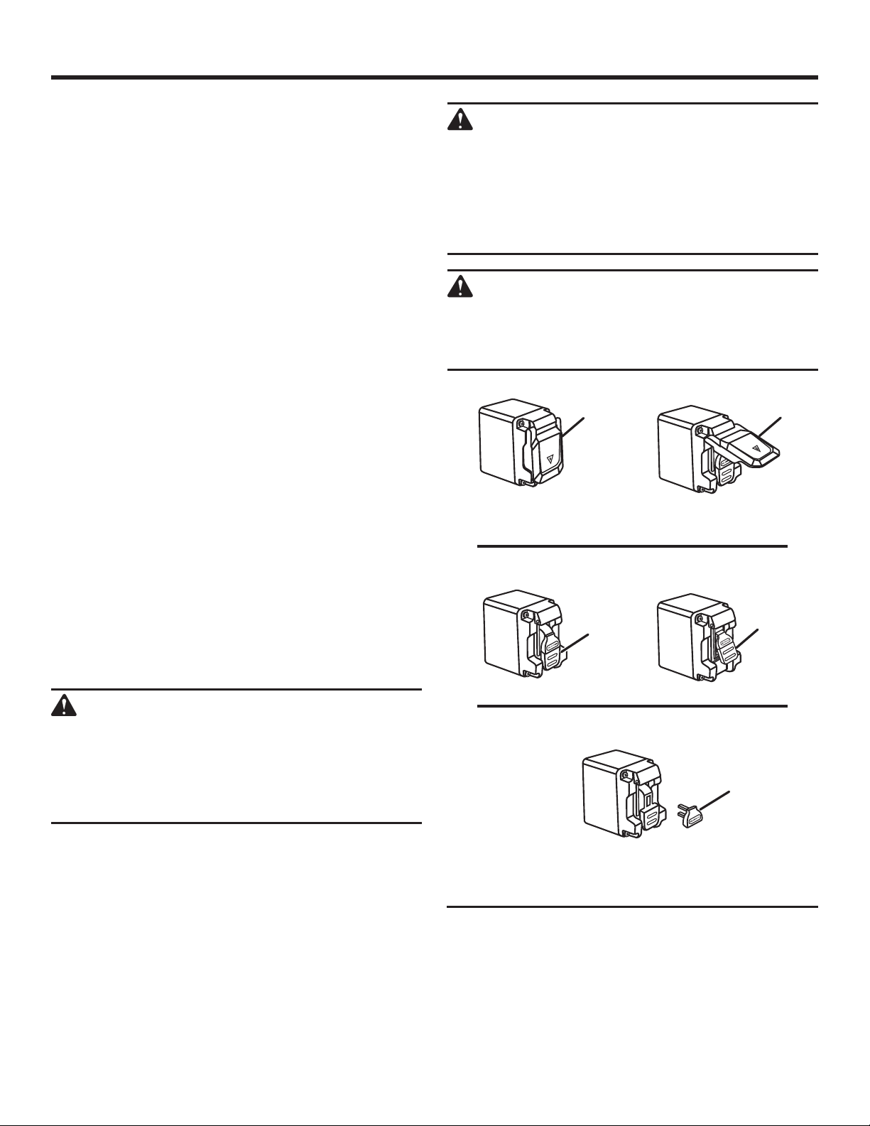
SWITCH ASSEMBLY
See Figure 6.
This saw is equipped with a switch assembly that has a
built-in locking feature. This feature is intended to prevent
unauthorized and possible hazardous use by children and
others.
NOTE: This saw has a switch cover. Raise the cover to
access the switch.
TO TURN YOUR SAW ON:
With the switch key inserted into the switch, lift the switch
button to turn ON ( l ).
TO TURN YOUR SAW OFF:
Press the switch button down to turn OFF ( O ).
TO LOCK YOUR SAW:
Press the switch button down.
Remove the switch key from the switch and store in a
safe, secure location.
WARNING:
ALWAYS make sure your workpiece is not in
contact with the blade before operating the
switch to start the tool. Failure to heed this
warning could cause the workpiece to be kicked
back toward the operator and result in serious
personal injury.
WARNING:
To reduce the risk of accidental starting, always
make sure the switch is in the OFF ( O ) position
before plugging tool into the power source.
SWITCH
COVER
NOTE: For clarity, the cover is not shown
in the illustrations below.
SWITCH OFF
SWITCH
SWITCH
ON
SWITCH
COVER
SWITCH
WARNING:
Always remove the switch key when the tool is
not in use and keep it in a safe place. In the event
of a power failure, turn the switch OFF ( O ) and
remove the key. This action will prevent the tool
from accidentally starting when power returns.
NOTE: The cover does not need to be removed
13 - English
Find Quality Products Online at: [email protected]
www.GlobalTestSupply.com
SWITCH IN LOCKED POSITION
SWITCH KEY
to remove the switch key.
REMOVED
Fig. 6
Page 14
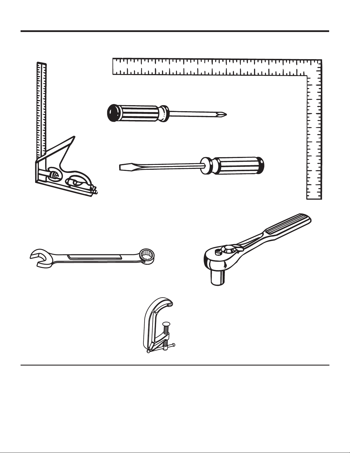
TOOLS NEEDED
The following tools (not included or drawn to scale) are needed for assembly and adjustments:
FRAMING SQUARE
PHILLIPS
SCREWDRIVER
FLATHEAD
SCREWDRIVER
COMBINATION
SQUARE
WRENCH
4 mm, 8 mm, 10 mm, 13 mm, 14 mm
SOCKET WRENCH
(8 mm, 13 mm SOCKET)
C-CLAMPS
Fig. 7
14 - English
Find Quality Products Online at: [email protected]
www.GlobalTestSupply.com
Page 15
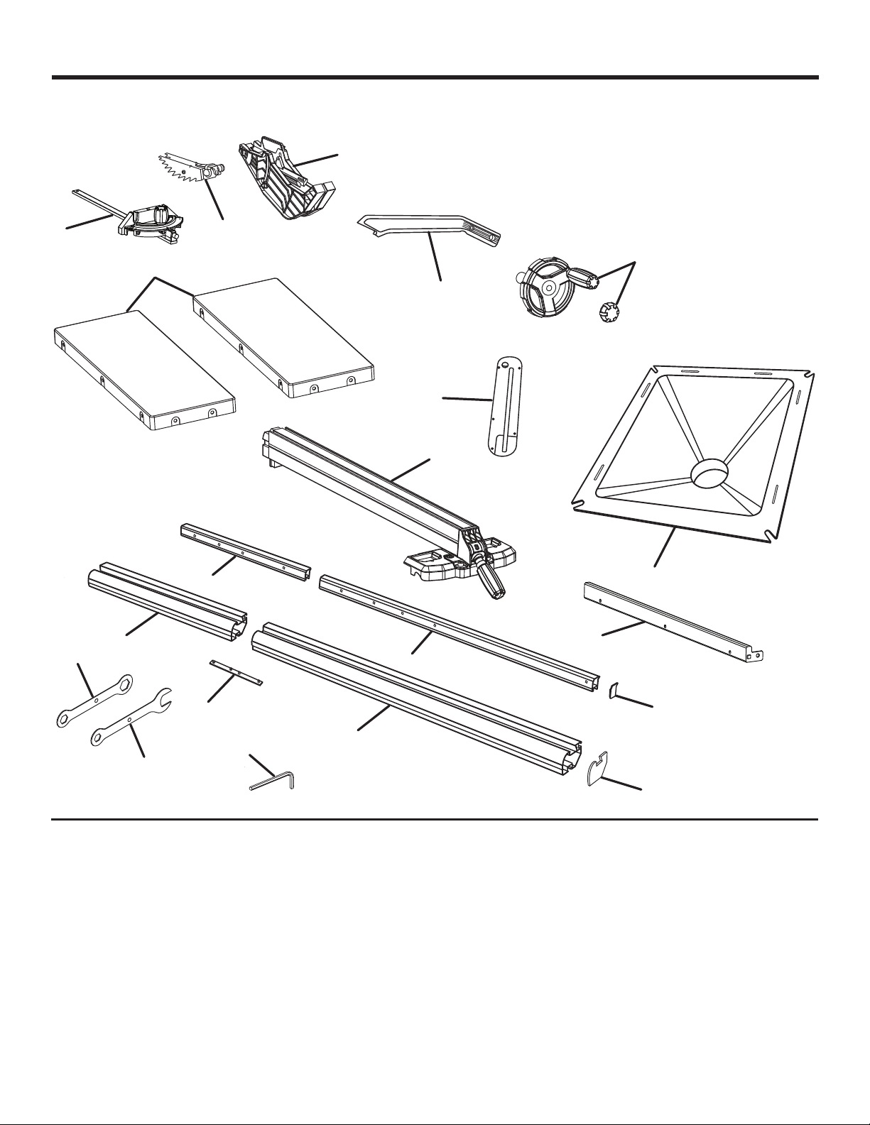
LOOSE PARTS
The following items are included with the table saw:
A
C
N
L
I
B
E, F
G
Q
D
K
O
K
P
M
L
J
H
A. Blade Guard .............................................................. 1
B. Anti-Kickback Pawls ................................................. 1
C. Miter Gauge ............................................................... 1
D. Rip Fence .................................................................. 1
E. Height Adjusting Handwheel, Washer, and Knob ..... 1
F. Bevel Adjusting Handwheel, Washer, and Knob ....... 1
G. Push Stick ................................................................. 1
H. Blade Wrench, open end ........................................... 1
I. Blade Wrench, closed end ........................................ 1
J. Hex Keys (3 mm, 4 mm, 5 mm, 6 mm, 8 mm)........... 1
K. Rear Rail .................................................................... 2
L. Front Rail ................................................................... 2
15 - English
Find Quality Products Online at: [email protected]
www.GlobalTestSupply.com
M. Rail Connector Bar .................................................... 3
N. Table Extensions ....................................................... 2
O. Spreader Bar ............................................................. 1
P. Dust Chute ................................................................ 1
Q. Throat Plate ............................................................... 1
R. Front End Cap (left and right) .................................... 2
S. Back End Cap (left and right) .................................... 2
Not shown:
T. Fastener Pack - Large (contents noted on pack) ...... 1
U. Fastener Pack - Small (contents noted on pack) ...... 1
V. Caster Fastener Bag - Small ..................................... 1
S
R
Fig. 8
Page 16
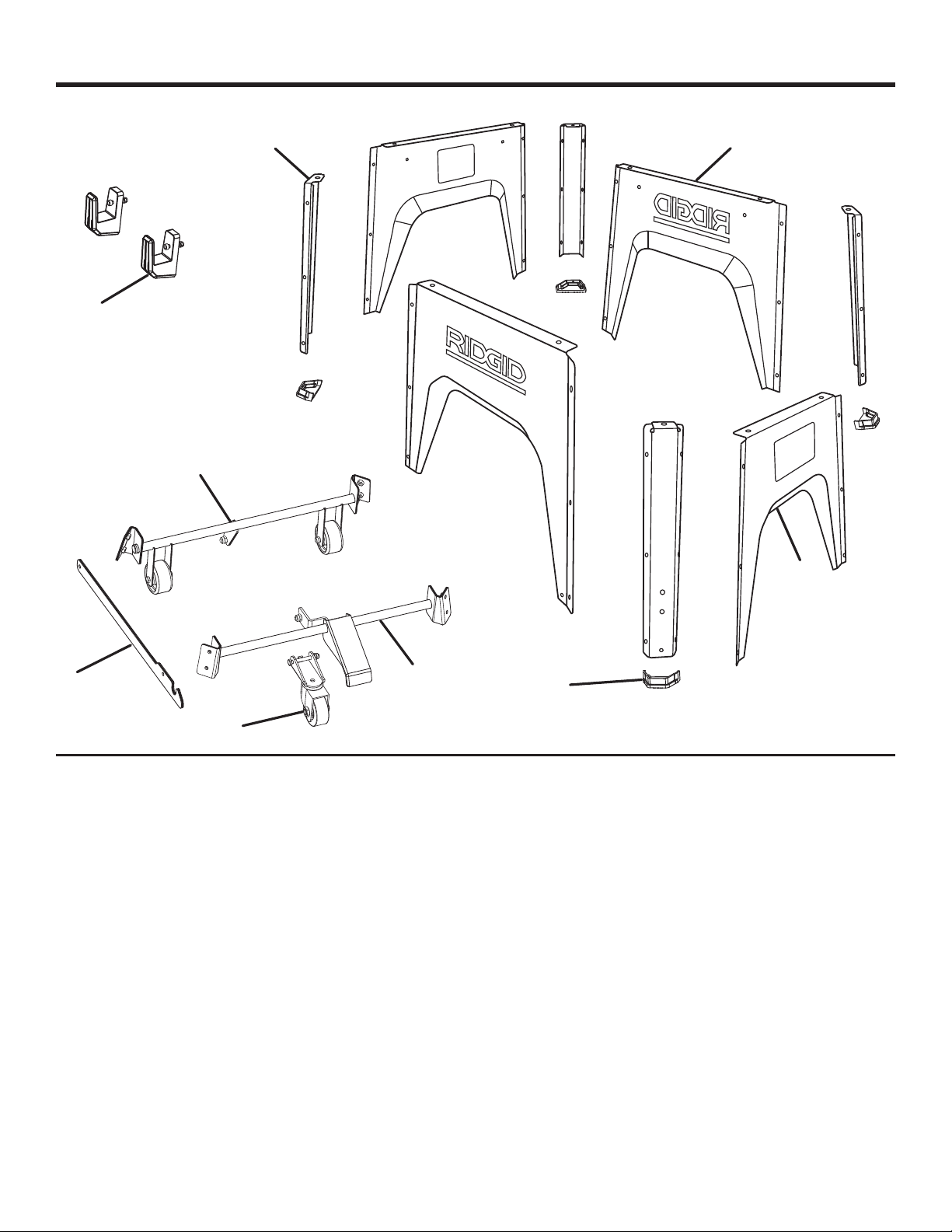
LOOSE PARTS
C
H
F
A
B
E
D
A. Leg Stand Side Sections ........................................... 2
B. Leg Stand Front and Back ......................................... 2
C. Outer Corners ............................................................ 4
D. Caster Assembly........................................................ 1
E. Center Support .......................................................... 1
G
I
Fig. 9
F. Rear Axle Assembly ................................................... 1
G. Front Axle .................................................................. 1
H. Rip Fence Storage Brackets ...................................... 2
I. Foot ........................................................................... 4
16 - English
Find Quality Products Online at: [email protected]
www.GlobalTestSupply.com
Page 17
ASSEMBLY
UNPACKING
This product requires assembly.
Carefully lift the saw from the carton and place it on a
level work surface.
NOTE: This tool is heavy. To avoid back injury, keep your
knees bent and lift with your legs, not your back, and get
help when needed.
WARNING:
Do not attempt to modify this tool or create
accessories not recommended for use with this
tool. Any such alteration or modification is misuse
and could result in a hazardous condition leading
to possible serious personal injury.
WARNING:
Do not use this product if any parts on the
Loose Parts List are already assembled to
your product when you unpack it. Parts on this
list are not assembled to the product by the
manufacturer and require customer installation.
Use of a product that may have been improperly
assembled could result in serious personal injury.
Inspect the tool carefully to make sure no breakage or
damage occurred during shipping.
Do not discard the packing material until you have carefully
inspected and satisfactorily operated the tool.
NOTE: A box containing some of the Loose Parts is
inside the saw cabinet. Also, remove the foam block from
between the saw’s housing and the motor.
The saw is factory set for accurate cutting. After assembling
it, check for accuracy. If shipping has influenced the
settings, refer to specific procedures explained in this
manual.
If any parts are damaged or missing, please call
1-866-539-1710 for assistance.
WARNING:
If any parts are damaged or missing, do not
operate this tool until the parts are replaced. Use
of this product with damaged or missing parts
could result in serious personal injury.
WARNING:
Do not connect to power supply until assembly
is complete. Failure to comply could result in
accidental starting and possible serious personal
injury.
WARNING:
Do not lift the saw without help. Hold it close
to your body. Keep your knees bent and lift
with your legs, not your back. Ignoring these
precautions can result in back injury.
WARNING:
Never stand directly in line with the blade or allow
hands to come closer than 3 in. to the blade. Do
not reach over or across the blade. Failure to
heed this warning can result in serious personal
injury.
WARNING:
To avoid serious personal injury, never operate
the saw if it is not mounted to the supplied leg
stand. NEVER operate the saw on the floor.
17 - English
Find Quality Products Online at: [email protected]
www.GlobalTestSupply.com
Page 18
ASSEMBLY
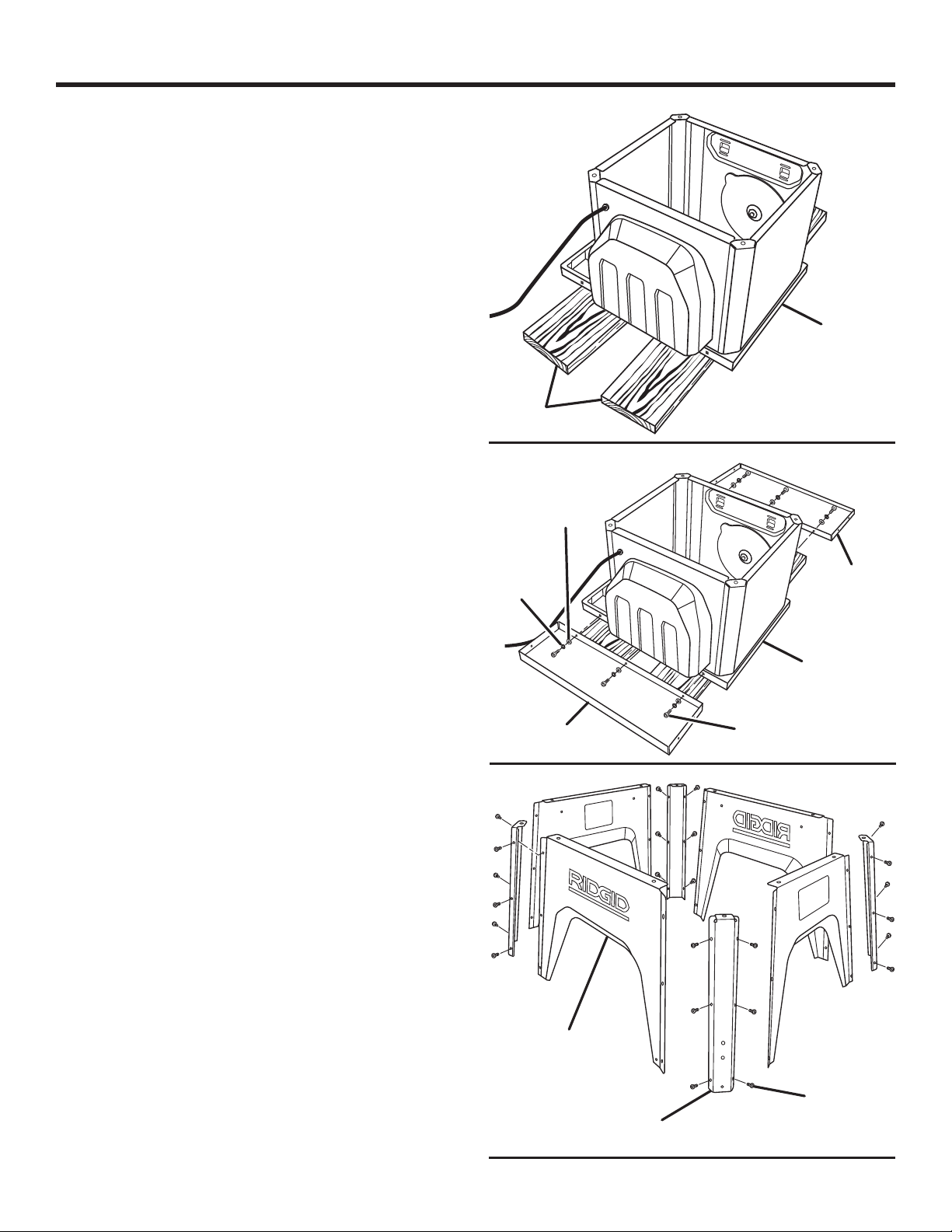
INSTALLING THE TABLE EXTENSIONS
See Figures 10 - 11.
NOTE: It is helpful to place two inch-thick boards on the floor
before lifting the saw table and motor housing from the box.
This will make it easier to assemble parts, and to move the
saw and set it upright.
Lift the saw table and motor housing from the box and
position it on the boards as shown.
Loosen the plastic wrap from the table and lift each side
to remove the wrapping.
From the large fastener pack, locate the following parts:
Bolts (M10 x 25 mm) ..................................................... 6
Lock washers (M10) ...................................................... 6
Flat washers (M10)........................................................ 6
With the table saw in the upside down position, place a
table extension against the table top, on the same side as
the power cord. The larger holes in the extension should
be aligned with the holes in the saw table.
Make sure the edges of the table extensions are aligned
with the edges of the table.
Insert a lock washer and flat washer over a bolt. Thread
the bolt into the holes in the table extension and saw
table. Repeat for the two remaining holes.
Repeat above step on the other table extension.
Using an 8 mm socket, tighten the socket head bolts. Do
not tighten completely.
ASSEMBLING THE LEG STAND
See Figure 12.
Locate the following parts:
Leg stand sections ....................................................... 4
Outer corners ................................................................ 4
From the small fastener pack, locate the following parts:
Bolts (M6 x 10 mm) ..................................................... 24
Place an outer corner outside a leg stand section.
NOTE: The top of the outer corner has a bent tab and
hole for assembly to the saw cabinet.
Insert a bolt into each of the three holes and finger tighten.
Repeat with remaining corners and leg stand sections.
Using a 4 mm hex key, tighten all bolts securely.
NOTE: The front of the stand is the section with the
English WARNING label attached.
BOARDS
WASHER
LOCK
WASHER
TABLE
EXTENSION
SAW
TABLE
Fig. 10
FLAT
TABLE
EXTENSION
SAW
TABLE
BOLT
Fig. 11
LEG STAND
SECTION
BOLT
OUTER
CORNER
18 - English
Find Quality Products Online at: [email protected]
www.GlobalTestSupply.com
Fig. 12
Page 19
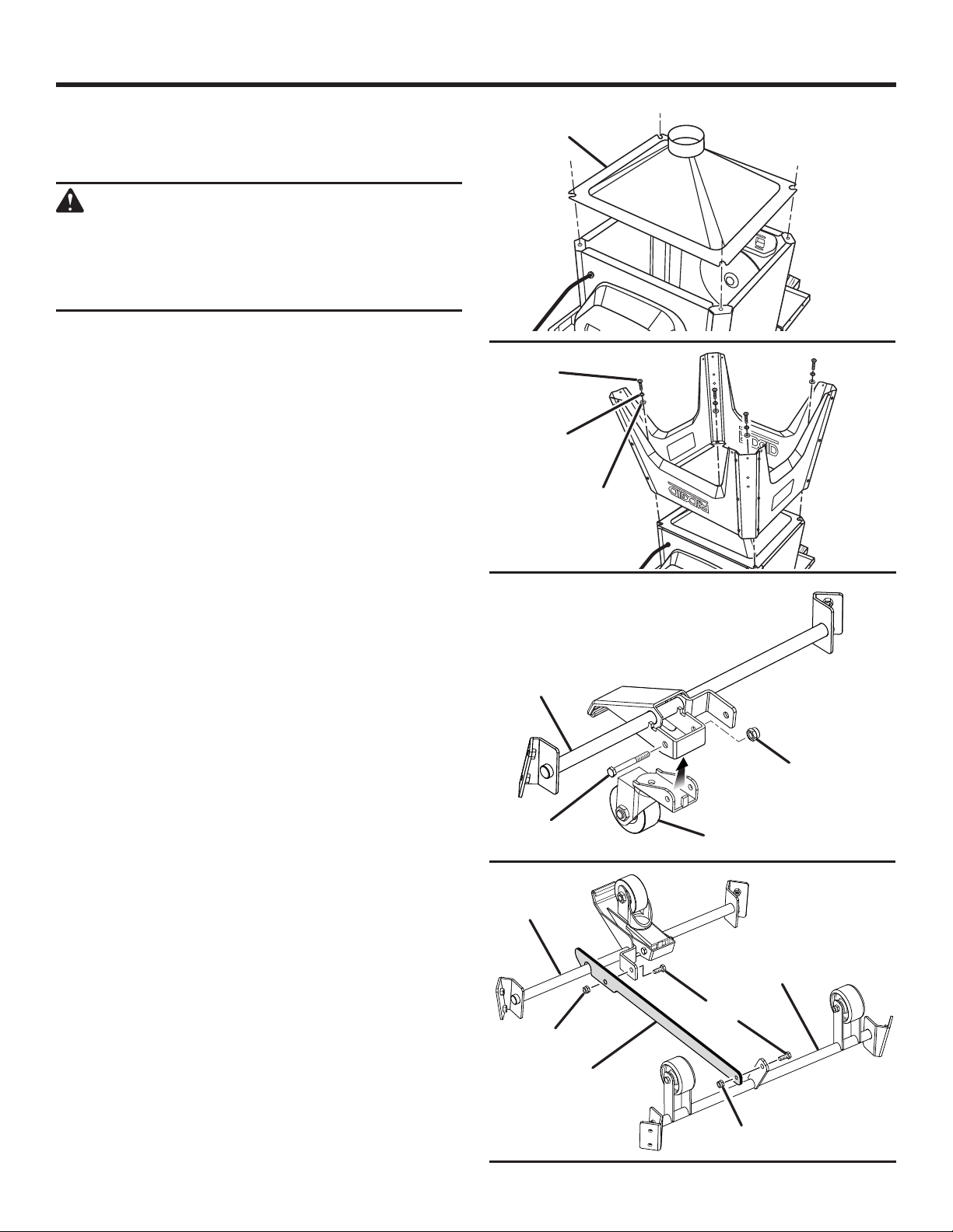
ASSEMBLY
ASSEMBLING THE LEG STAND ONTO THE
SAW CABINET
See Figures 13 - 14.
WARNING:
Only install the dust chute when using a four
inch dust collection system. Failure to heed this
warning could result in serious personal injury or
death. Clean saw dust from the cabinet regularly.
NOTE: Make sure the foam block has been removed before
installing the dust chute.
Place the dust chute on top of the saw cabinet. The word
“FRONT” and the arrow should align with front panel of
the saw and the registration ridges should align with the
grooves.
Place the assembled leg stand over the dust chute as
shown.
Locate the following from the small fastener pack:
Flat washers.................................................................. 4
Lock washers ................................................................ 4
Bolts .............................................................................. 4
Slide a lock washer and a flat washer over each bolt.
Thread a bolt into each of the four holes at the corners
of the leg stand.
Using a 6 mm hex key, securely tighten the bolts.
ASSEMBLING THE CASTER SET
See Figures 15 - 16.
Remove the bolts and nuts from the caster assembly and
the front axle assembly.
NOTE: Use a 13 mm wrench and a 14 mm wrench for the
nuts and the bolts.
Attach the caster to the front axle by sliding the bolt
through the holes and placing the nut over the bolt.
Securely tighten the nut.
Remove the bolts and nuts from the rear and front axle
assemblies.
NOTE: Use a 6 mm hex wrench to hold the bolt and a
13 mm wrench to loosen the nut.
Position the front and rear axles as shown.
Attach the center support to the front axle assembly.
Slide the bolt through the hole in the axle center piece
and thread the nut over the bolt. Tighten the nut.
Attach the center support to the rear axle.
DUST CHUTE
BOLT
LOCK
WASHER
FRONT AXLE
ASSEMBLY
BOLT
FRONT AXLE
ASSEMBLY
NUT
FLAT
WASHER
CASTER
REAR AXLE
ASSEMBLY
BOLT
Fig. 13
Fig. 14
NUT
Fig. 15
CENTER
SUPPORT
NUT
19 - English
Find Quality Products Online at: [email protected]
www.GlobalTestSupply.com
Fig. 16
Page 20
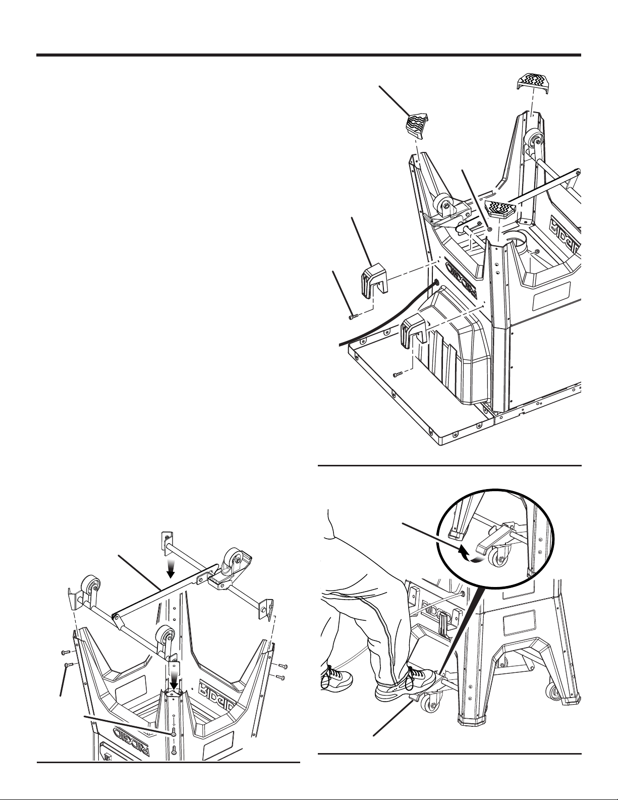
ASSEMBLY
INSTALLING THE CASTER SET TO THE LEG
STAND
See Figure 17.
Slide the caster set into the leg stand, aligning the holes
in the caster assembly with the holes in the leg stand.
NOTE: Position the pedal as shown, so that it will be on
the left of the saw when the saw is upright.
Locate the following from the small fastener pack:
Bolts (M8 x 16 mm) ....................................................... 8
Insert the bolts into the holes in the leg stand and through
the holes in each caster.
Using a 5 mm hex key, securely tighten the bolts.
Position the feet on the stand by pressing them into place.
INSTALLING RIP FENCE STORAGE BRACKETS
See Figure 18.
Remove the pre-installed bolt and nut from each bracket.
Insert a bolt through the hole in each bracket, aligning it
as shown with the hole in the stand.
Thread the nut over the bolt. Using a 5 mm hex key,
securely tighten each bolt.
FEET
NUT
BRACKET
BOLT
SETTING THE SAW UPRIGHT
See Figure 19.
NOTE: The saw is heavy and requires several people for
this procedure.
Tilt the saw until it rests on the back side of the cabinet.
Raise saw carefully until it sits upright.
To raise the saw table, step down on the pedal until it
locks.
Roll the table saw to the desired location making sure
the surface is firm and level.
Pull up on the pedal to slowly lower the table saw.
CASTER
ASSEMBLY
Fig. 18
TO LOWER
SOCKET
HEAD BOLT
Fig. 17
20 - English
Find Quality Products Online at: [email protected]
www.GlobalTestSupply.com
PEDAL
Fig. 19
Page 21
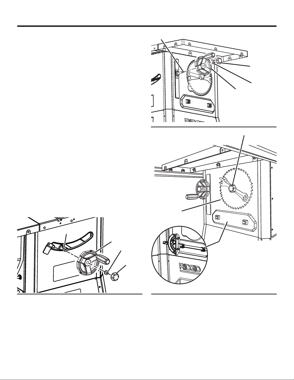
ASSEMBLY
INSTALLING THE HEIGHT ADJUSTING
HANDWHEEL
See Figure 20.
NOTE: The height adjusting handwheel knob and the bevel
adjusting handwheel knob act as locks. To lock the wheel
for operation, turn the knob clockwise until it is securely
tightened.
Slide the handwheel over the bolt above the bevel
adjustment scale on the front of the saw.
Slide the washer over the bolt.
Screw the knob securely onto the bolt.
INSTALLING THE BEVEL ADJUSTING
HANDWHEEL
See Figure 21.
Slide the bevel adjusting handwheel over the bolt on the
side of the saw.
Slide the washer over the bolt.
Screw the knob securely onto the bolt.
ACCESSORY STORAGE
See Figure 22.
Storage for the blade, blade wrench and miter gauge is
located on the side of the saw. The miter gauge may be
stored by sliding it into the slots.
The push stick contains a magnet. When not in use, the push
stick may be stored at a convenient location on the saw.
BOLT
KNOB
WASHER
BEVEL
ADJUSTING
HANDWHEEL
Fig. 21
KNOB
BOLT
HEIGHT
ADJUSTING
HANDWHEEL
WASHER
KNOB
Fig. 20
BLADE AND
WRENCH
STORAGE
MITER GAUGE
STORAGE
Fig. 22
21 - English
Find Quality Products Online at: [email protected]
www.GlobalTestSupply.com
Page 22
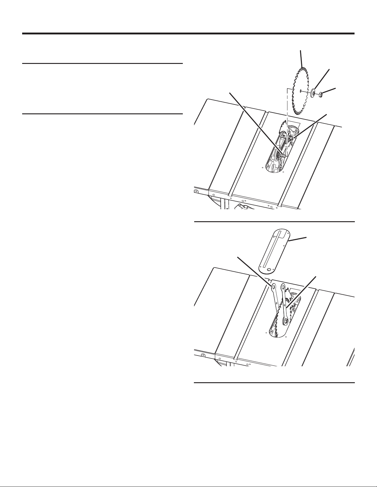
ASSEMBLY
INSTALLING THE BLADE
See Figure 23 - 24.
NOTICE:
To work properly, the saw blade teeth must point
down toward the front of the saw. Failure to heed
this warning could cause damage to the saw
blade, the saw, or the workpiece.
The blade and blade wrenches are located on the side of the
saw in the storage area. Twist the knob counterclockwise
to remove it.
Unplug the saw.
Remove the blade and two blade wrenches from the
storage area.
Raise the blade arbor by unlocking the height adjusting
handwheel and turning it clockwise.
Make sure the bevel lock knob is tightened.
Remove the blade washer and the blade nut from the
arbor shaft.
Unlock the release lever by pulling it up.
Place the new blade on the arbor shaft (blade teeth must
point down toward the front of the saw to work properly).
Place the blade washer and the blade nut over the arbor
shaft. Be sure the dome side of the blade washer faces
out from the blade and that all items are snug against the
arbor housing.
Using the open end blade wrench, place the flat open
end into the flats on the arbor shaft.
Insert the closed end of the other blade wrench over the
hex nut. Holding both wrenches firmly, push the closed
end wrench to the back of the machine. Make sure the
blade nut is securely tightened. Do not overtighten.
NOTE: Arbor shaft has right-hand threads.
Lock the release lever by pushing the lever down.
Rotate the blade by hand to make sure it turns freely.
Lower the blade by unlocking the height adjusting
handwheel and turning it counterclockwise.
Install the throat plate as described later.
Check all clearances for free blade rotation.
When finished, check all clearances for free blade rotation.
Refer to To Set the Rip Fence Scale Indicator to the Blade
in the Operation section earlier in this manual. In cutting
operations, the scale will be set to the side of the blade
where the cut will be measured and made.
BLADE
ARBOR
OPEN END
BLADE
WRENCH
BLADE
BLADE
WASHER
BLADE
NUT
RELEASE
LEVER
Fig. 23
THROAT
PLATE
CLOSED END
BLADE
WRENCH
Fig. 24
22 - English
Find Quality Products Online at: [email protected]
www.GlobalTestSupply.com
Page 23

ASSEMBLY
TO INSTALL/ALIGN/REMOVE THE THROAT
PLATE
See Figure 25.
WARNING:
The throat plate must be level with the saw
table. If the throat plate is too high or too low,
the workpiece can catch on the uneven edges
resulting in binding or kickback which could
result in serious personal injury.
Lower the blade by unlocking the height adjusting
handwheel and turning it counterclockwise.
To install the throat plate, first slip the tab underneath the
saw table at the back of the saw and then push down to
secure in place.
NOTE: The throat plate may move up and down over
time. If necessary, adjust the screws through the throat
plate until it is level with the saw table.
To remove the throat plate, place your index finger in
the hole and lift the front end, pulling the throat plate out
toward the front of the saw.
NOTE: Front rail sections have a rip scale printed on them.
In the illustrations, rail connector bars are inserted into the
long rail section first.
Insert half of each rail connector bar into the grooves in
the rail sections.
Using a 3 mm hex key, attach the connector bar to the
rail by partially tightening the set screws.
Attach a second rail connector bar in the same way as
the first one.
NOTE: The left side rail section is shorter than the right side.
Slide the second front rail section onto the first, over the
attached rail connector bars. Partially tighten set screws.
FRONT RAIL ASSEMBLY
LONG RAIL
SECTION
RIP SCALE
RAIL
CONNECTOR BAR
ASSEMBLING THE RAILS
See Figures 26 - 28.
To assemble the front rail:
NOTE: Do not completely tighten set screws until all front
rail pieces are assembled and you have made sure the rail
will lie flat and level.
THROAT
PLATE
BLADE
TAB
HEX KEY
FRONT RAIL
SECTIONS
SET SCREWS
SHORT RAIL SECTION
REAR RAIL ASSEMBLY
CONNECTOR BAR
RAIL
CONNECTOR BAR
Fig. 26
RAIL
CONNECTOR BAR
Fig. 27
RAIL
REAR RAIL
SCREWS
Find Quality Products Online at: [email protected]
www.GlobalTestSupply.com
Fig. 25
23 - English
SECTIONS
Fig. 28
Page 24
ASSEMBLY
Place the assembled rail sections on a flat surface and
make sure the rail lies flat and level. There should be no
gaps between the two sections.
Securely tighten all set screws.
To assemble the rear rail:
Slide the remaining rail connector bar into the slot in the
a rear rail section.
Assemble the rear rail sections in the same way as the
front rail. Make sure the rail lies flat and level and there
are no gaps between the two sections.
Securely tighten all set screws.
INSTALLING THE RAILS ONTO THE SAW
TABLE
See Figures 29 - 32.
Take the following from the large fastener pack:
Hex head bolts (M8 x 30 mm for the front rail) ............. 9
Bolts (M8 x 20 mm for the rear rail) .............................. 9
Nuts (M8: 10 for the front rail, 6 for the rear rail) ........ 16
NOTE: One M8 x 30 bolt, one M8 x 20 bolt, and four of
the nuts will be needed to secure the spreader bar to the
front and rear rails.
To install the front rail:
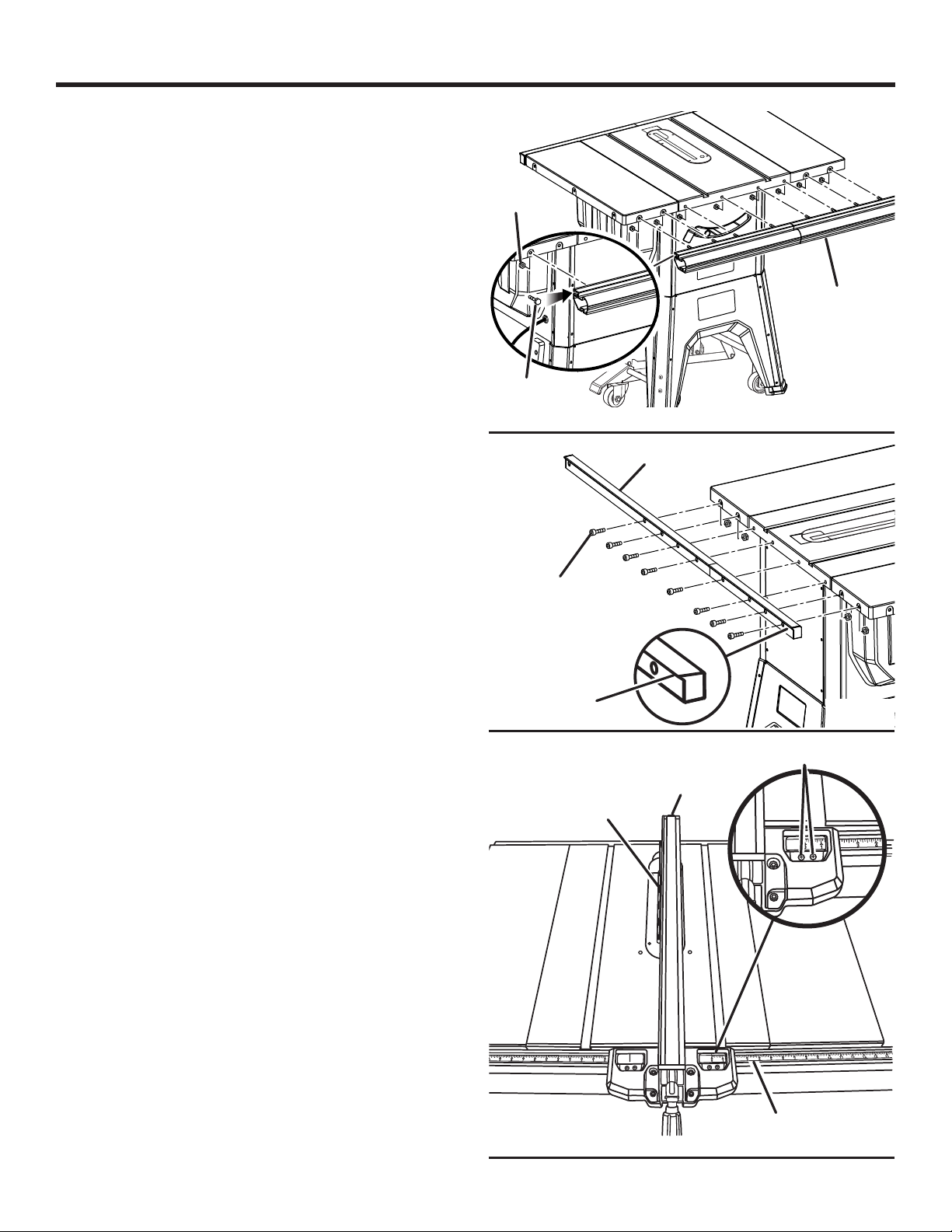
Slide eight hex head bolts into the groove on the back of
the assembled front rail.
Align the bolts with and insert the bolts into the holes on
the front of the saw table and table extensions.
Using a 13 mm wrench, tighten the four center nuts. Do
not tighten completely.
Tighten the four outer nuts. Do not tighten completely.
To install the rear rail:
Insert eight bolts into the holes on the back of the saw
table and table extensions.
NOTE: Position the rear rail with the slotted side on the
bottom and the lip on the top and facing out.
Using a 6 mm hex key, tighten the four center bolts. Do
not tighten completely.
Tighten the four outer nuts. Do not tighten completely.
To check the table and rail position:
Raise the blade by unlocking the height adjusting
handwheel and turning it clockwise.
Gently place the rip fence against the blade as shown.
The mark on the right side indicator should be at zero on
the rip scale.
NOTE: Do not lock the rip fence handle at this point.
If the rip fence indicator is not at zero, slightly loosen the
bolts and nudge the rails until the mark is at zero.
HEX NUT
HEX HEAD
BOLT
BOLT
FRONT RAIL
Fig. 29
REAR RAIL
LIP
Fig. 30
SCREWS
RIP FENCE
BLADE
RIP FENCE
ZERO
INDICATOR
SCALE
24 - English
Find Quality Products Online at: [email protected]
www.GlobalTestSupply.com
Fig. 31
Page 25
ASSEMBLY
Carefully tighten the four center nuts for the rail.
With the rip fence lying on top of the saw table, check to
see that the rip fence slides freely across the table and
table extension and will not catch or drag at any point.
There should be an equal gap between the saw table and
the bottom of the rip fence from the front to back of the
rip fence, on both sides of the blade.
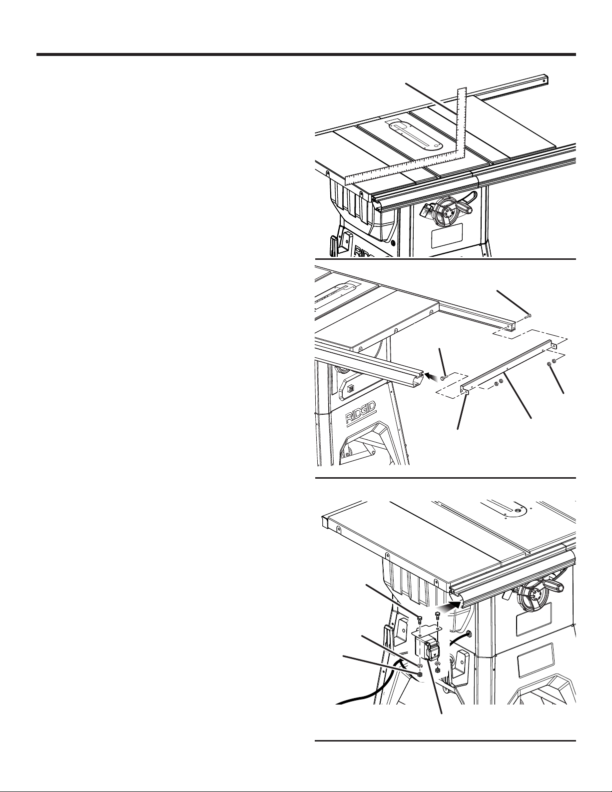
Lay a framing square on each side of the table top as
shown to make sure the table extensions are level with
the top.
If the table extensions and rails are flat and level, securely
tighten the four center nuts on the front rail and the four
center bolts on the rear rail.
Securely tighten the four outer nuts and bolts on each
rail.
Check the table and extensions to make sure all assembled
parts are flush and level.
If the table extensions, rip fence, and rails are not level,
make adjustments by slightly loosening and retightening
the bolts and nuts, and repositioning the rails until they
are level and flush with the table top.
INSTALLING THE SPREADER BAR
See Figure 33.
The bolts and nuts for the spreader bar were removed from
the large fastener pack during installation of the rails.
Position the spreader bar at the end of the rails with the
tabs facing away from the saw table.
Slide a hex head bolt into the groove on the front rail and
insert the bolt through the tab in the spreader bar. Thread
two hex nuts over the bolt and finger tighten.
Insert a bolt through the holes in the rear rail and spreader
bar tab.
Thread two hex nuts onto the bolt.
Using a 13 mm wrench, securely tighten all bolts.
FRAMING SQUARE
HEX HEAD
BOLT
TAB
45
Fig. 32
BOLT
NUT
SPREADER
BAR
Fig. 33
MOUNTING THE SWITCH ASSEMBLY
See Figure 34.
Take the following from the large fastener pack:
Hex head bolts (M6 x 14 mm)....................................... 2
Lock washers (6 mm) .................................................... 2
Hex nuts (6 mm)............................................................ 2
Slide two hex head bolts into the middle groove in the
front rail.
Insert the bolts through the holes in the switch assembly
mounting plate.
Thread a lock washer and nut over each of the bolts.
Securely tighten the hex nuts using a 10 mm wrench.
25 - English
Find Quality Products Online at: [email protected]
www.GlobalTestSupply.com
HEX HEAD
BOLT
LOCK
WASHER
NUT
SWITCH
ASSEMBLY
Fig. 34
Page 26
ASSEMBLY
INSTALLING END CAPS
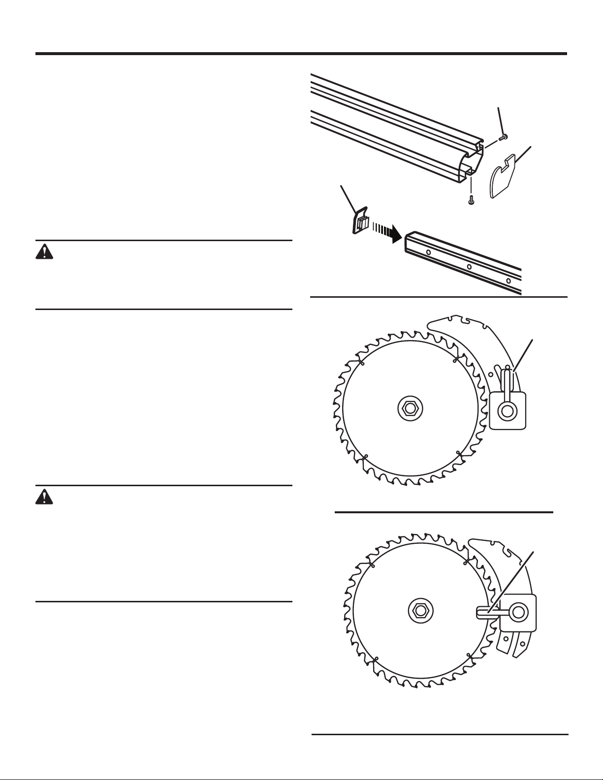
See Figure 35.
Align the end caps of the front rail to the end of the rail.
Secure using self-tapping pan head screw (M4) in each
hole using a Phillips screwdriver.
Push rear rail end caps into position at each end of the
rail.
TO CHANGE RIVING KNIFE POSITIONS
See Figure 36.
This saw is shipped with a riving knife that should be placed
in the “down” position for non-through cutting and must be
placed in the “up” position for all other cutting operations.
CAUTION:
Use caution when reaching inside the throat in
the saw table. Blade contact, even when the
blade is still, may result in injury to hands or arms.
Unplug the saw.
To place in the “up” position for all through cutting:
Remove the throat plate.
Raise the blade by unlocking the height adjusting
handwheel and turning it clockwise.
Unlock the release lever by pulling it up.
Grasp the riving knife and pull it towards the right side of
the saw to release the riving knife from the spring-loaded
riving clamp.
Pull the riving knife up until the internal pins are engaged
and the riving knife is above the saw blade.
Lock the release lever by pushing the lever down.
SCREWS
FRONT RAIL
END CAP
REAR RAIL
END CAP
Fig. 35
RELEASE
LEVER
(UNLOCKED)
WARNING:
Make sure the release lever is fully seated. If the
release lever is difficult to lock, thoroughly clean
lever components using compressed air or a
clean soft cloth. Failure to completely lock the
release lever can allow the riving knife to change
position during saw use, which could result in
serious personaly injury.
Reinstall the throat plate.
To place riving knife in “down” position for all nonthrough cutting:
Remove the throat plate.
Raise the blade by unlocking the height adjusting
handwheel and turning it clockwise.
Unlock the release lever by pulling it up.
Push the riving knife down until it is below the saw blade.
Lock the release lever by pushing the lever down.
Reinstall the throat plate.
26 - English
Find Quality Products Online at: [email protected]
www.GlobalTestSupply.com
IN “UP” POSITION FOR THROUGH CUTTING
RELEASE
LEVER
(LOCKED)
IN “DOWN” POSITION FOR NON-THROUGH CUTTING
Fig. 36
Page 27
ASSEMBLY
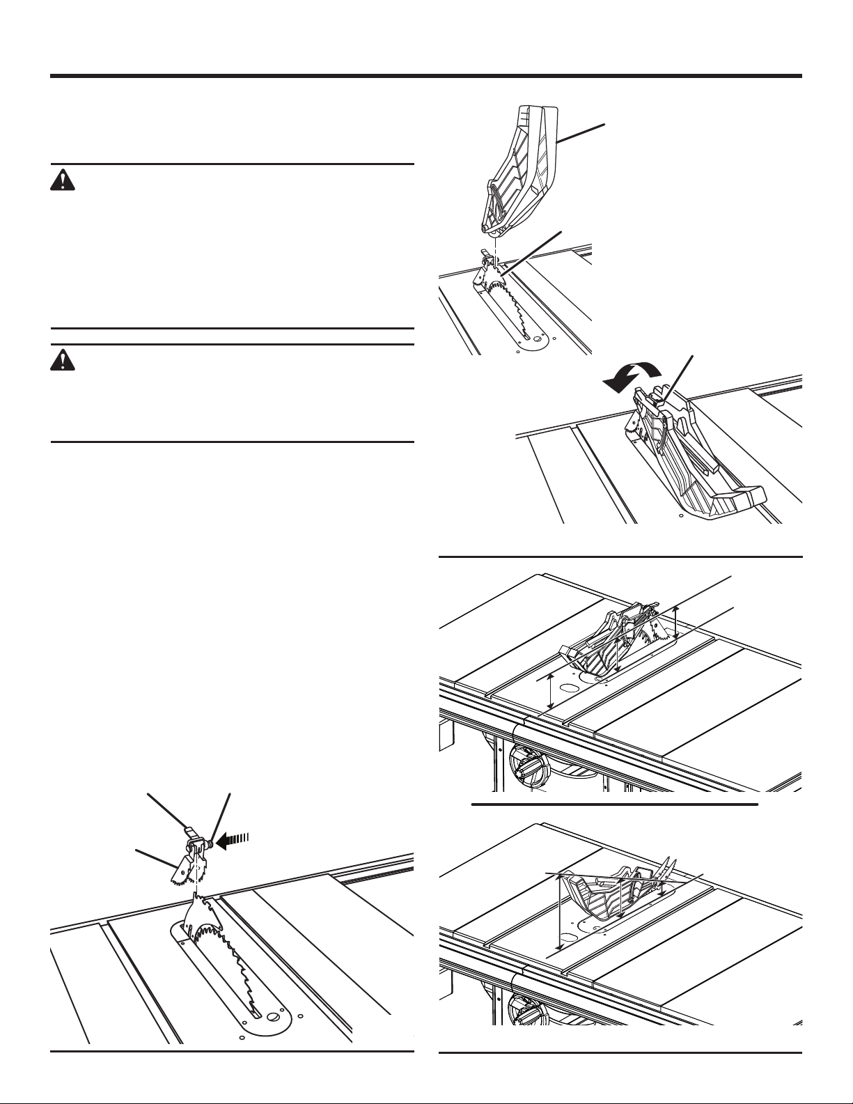
TO INSTALL THE ANTI-KICKBACK PAWLS AND
BLADE GUARD
See Figures 37 - 39.
WARNING:
Always install the blade guard and anti-kickback
pawls onto the riving knife in the “up” position
to provide proper blade coverage. Installing the
guarding components onto the riving knife in any
other position will prevent them from working
as designed, which could increase the risk of
serious personal injury.
WARNING:
Replace dull or damaged anti-kickback pawls.
Dull or damaged pawls may not stop a kickback
increasing the risk of serious personal injury.
NOTE: Anti-kickback pawls should only be installed for
through cuts.
Unplug the saw.
Raise the blade by unlocking the height adjusting
handwheel and turning it clockwise.
Place riving knife in “up” position.
To install anti-kickback pawls:
Press and hold the button on the right side of the anti-
kickback pawls.
Align the slot in the pawls over the rear notch in the riving
knife.
Push the pawl handle down snapping them into place
and release the button.
NOTE: Pull on the handle to make sure pawls are securely
locked.
BLADE
GUARD
RIVING
KNIFE
GUARD
LEVER
TO
LOCK
Fig. 38
CORRECT
PAWL
HANDLE
ANTI-KICKBACK
PAWLS
Find Quality Products Online at: [email protected]
BUTTON
Fig. 37
27 - English
www.GlobalTestSupply.com
INCORRECT
Fig. 39
Page 28
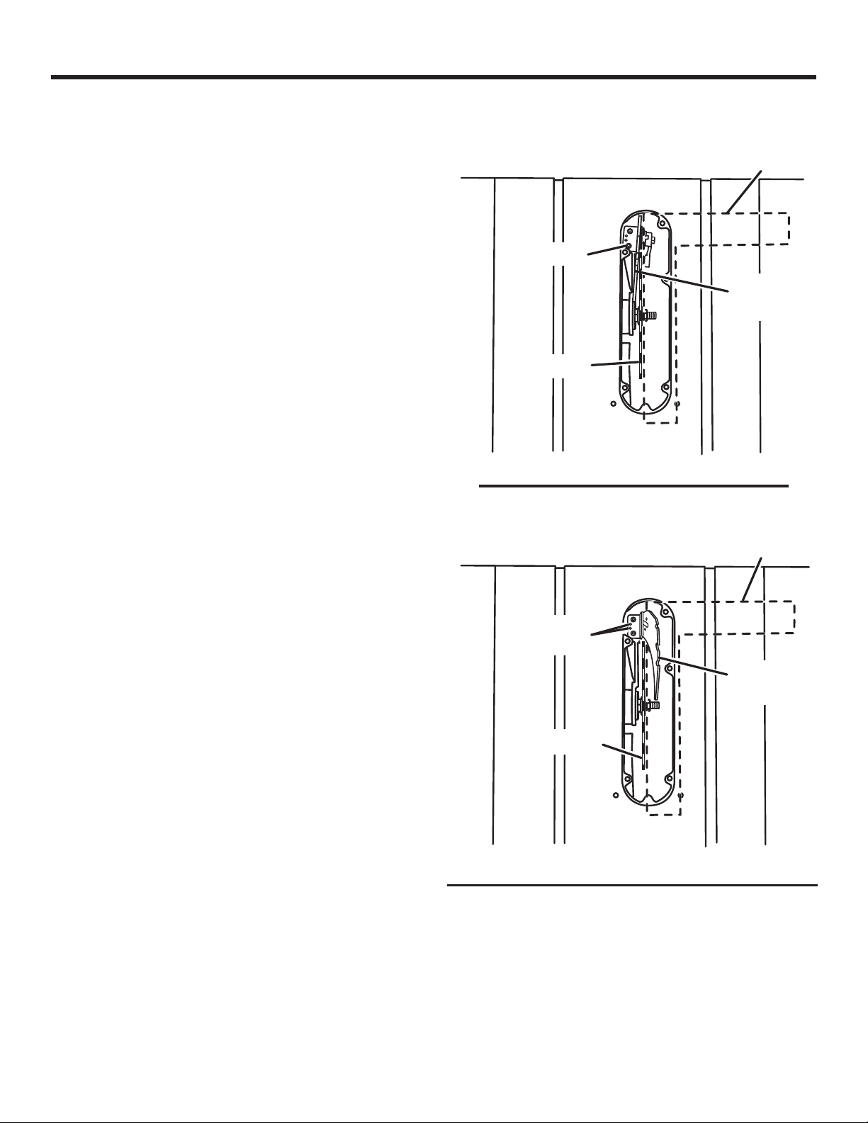
ASSEMBLY
To install blade guard:
Lift the guard lever up to unlock.
With the front of the blade guard raised and the guard lever
unlocked, lower the back of the guard into the middle slot
of the riving knife. Push the front of the guard down until
it is parallel to the table. If the blade guard is not parallel
to the table, the riving knife is not in the “up” position.
Lock the guard in place by pushing the guard lever down.
NOTE: Blade alignment can be adjusted for different blade
widths. Refer to: To Check and Align the Riving Knife and
Saw Blade. Check the blade guard assembly for clearances
and free movement.
TO CHECK AND ALIGN THE RIVING KNIFE AND
SAW BLADE
See Figure 40.
To check alignment of the riving knife:
Unplug the saw.
Raise the blade by unlocking the height adjusting
handwheel and turning it clockwise.
Remove the anti-kickback pawls and blade guard
assembly. Place a framing square or straight edge against
both the saw blade and the riving knife.
NOTE: Place framing square between carbide teeth and
measure from blade. This step will insure framing square
is square against blade from the front to back of blade.
The saw blade and riving knife are aligned when the
framing square contacts both the blade and riving knife
evenly with no gaps.
If the riving knife is out of alignment with the saw blade,
adjustment is needed. The riving knife must be in alignment
front to back (horizontally) and top to bottom (vertically).
To adjust (horizontally):
Remove the anti-kickback pawls and blade guard
assembly.
Using a 4 mm hex key, loosen the screws holding the
mounting bracket.
Reposition the riving knife left or right as needed to align
the riving knife with the saw blade.
Once properly aligned, securely retighten all screws.
Check again for squareness and continue to adjust if
needed.
To adjust (vertically):
Using a 2.5 mm hex key, loosen the set screws and screws
holding the mounting bracket.
Slowly turn the set screws until the riving knife is aligned
with the blade.
Once properly aligned, securely retighten all screws.
Check again for squareness and continue to adjust if
needed.
HORIZONTAL ADJUSTMENT
FRAMING
SQUARE
SCREW
RIVING
KNIFE
BLADE
VERTICAL ADJUSTMENT
FRAMING
SQUARE
SET
SCREWS
RIVING
KNIFE
BLADE
Fig. 40
28 - English
Find Quality Products Online at: [email protected]
www.GlobalTestSupply.com
Page 29
OPERATION
WARNING:
Do not allow familiarity with tools to make you
careless. Remember that a careless fraction of a
second is sufficient to inflict serious injury.
WARNING:
Always wear eye protection with side shields
marked to comply with ANSI Z87.1. Failure to do
so could result in objects being thrown into your
eyes, resulting in possible serious injury.
WARNING:
Do not use any attachments or accessories
not recommended by the manufacturer of this
tool. The use of attachments or accessories not
recommended can result in serious personal
injury.
CAUSES OF KICKBACK
Kickback can occur when the blade stalls or binds, kicking
the workpiece back toward you with great force and speed. If
your hands are near the saw blade, they may be jerked loose
from the workpiece and may contact the blade. Obviously,
kickback can cause serious injury, and it is well worth using
precautions to avoid the risks.
Kickback can be caused by any action that pinches the blade
in the wood, such as the following:
Making a cut with incorrect blade depth
Sawing into knots or nails in the workpiece
Twisting the wood while making a cut
Failing to support work
Forcing a cut
Cutting warped or wet lumber
Using the wrong blade for the type of cut
Not following correct operating procedures
Misusing the saw
Failing to use the anti-kickback pawls
Cutting with a dull, gummed-up, or improperly set blade
WARNING:
Although many of the illustrations in this manual are
shown with the blade guard removed for clarity, do
not operate the saw without the blade guard unless
specifically instructed to do so.
APPLICATIONS
You may use this tool for the purposes listed below:
Straight line cutting operations such as cross cutting,
ripping, mitering, beveling, and compound cutting
Dado or molding cuts with optional accessories
Cabinet making and woodworking
NOTE: This table saw is designed to cut wood and wood
composition products only.
BASIC OPERATION OF THE TABLE SAW
The 3-prong plug must be plugged into a matching outlet
that is properly installed and grounded according to all local
codes and ordinances. Improper connection of the equipment
can result in electric shock. Check with an electrician or
service personnel if you are unsure about proper grounding.
Do not modify the plug; if it will not fit the outlet, have the
correct outlet installed by a qualified electrician. Refer to the
Electrical section earlier in this manual.
AVOIDING KICKBACK
Always use the correct blade depth setting. The top of
the blade teeth should clear the workpiece by 1/8 in. to
1/4 in.
Inspect the work for knots or nails before beginning a
cut. Knock out any loose knots with a hammer. Never
saw into a loose knot or nail.
Always use the rip fence when rip cutting. Use the miter
gauge when cross cutting. This helps prevent twisting
the wood in the cut.
Always use clean, sharp, and properly-set blades. Never
make cuts with dull blades.
To avoid pinching the blade, support the work properly
before beginning a cut.
When making a cut, use steady, even pressure. Never
force cuts.
Do not cut wet or warped lumber.
Use extra caution when cutting some prefinished or
composition wood products as the anti-kickback pawls
may not always be effective.
Always guide your workpiece with both hands or with
push sticks and/or push blocks. Keep your body in a
balanced position to be ready to resist kickback should
it occur. Never stand directly in line with the blade.
Use of a featherboard will help hold the workpiece securely
against the saw table or fence.
Clean the saw, blade guard, under the throat plate, and
any areas where saw dust or scrap workpieces may gather.
Use the right type of blade for the cut being made.
Always use the riving knife for every operation where it
is allowed. The use of this device will greatly reduce the
risk of kickback.
29 - English
Find Quality Products Online at: [email protected]
www.GlobalTestSupply.com
Page 30
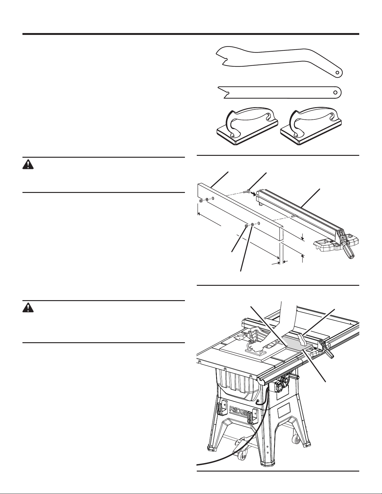
3/4 in.
OPERATION
CUTTING AIDS
See Figure 41.
Push sticks are devices that may be used for pushing a
workpiece through the blade in any rip cut. When making
non-through cuts or ripping narrow stock, always use a
push stick, push block, and/or featherboard so your hands
do not come within 3 inches of the saw blade. They can be
made in various sizes and shapes from scrap wood and
used in a specific project. The stick must be narrower than
the workpiece, with a 90˚ notch in one end and shaping for
a grip on the other end.
A push block has a handle fastened by recessed screws
from the underside. Use push blocks for narrow cuts and
all non-through cuts.
PUSH STICKS
PUSH BLOCKS
Fig. 41
CAUTION:
Be sure the screws in a push block are recessed to
avoid damaging the saw or workpiece.
AUXILIARY FENCE
An auxiliary fence is a device used to close the gap between
the rip fence and the saw table. Always make and use an
auxiliary fence when ripping material 1/8 in. or thinner.
HOW TO MAKE AND ATTACH AN AUXILIARY
FENCE (FOR RIP CUTTING THIN WORKPIECE)
See Figure 42.
An auxiliary fence may be made for the saw by cutting a
piece of wood to 3/4 in. thick, 3-1/2 in. wide, and 31 in. long.
To attach the auxiliary fence to the rip fence:
Drill two countersunk holes in the locations shown.
WARNING:
When mounting an auxiliary fence face, position
mounting hardware beyond arrows at right and left.
Keep fasteners away from blade.
AUXILIARY
FENCE
31 in.
NUT
WASHER
STOP
T-BOLT
RIP
FENCE
3-1/2 in.
Fig. 42
JIG
HANDLE
Slide two T-bolts (not included) into the rip fence groove
beyond the arrows at right and left of the label on the rip
fence.
Match the T-bolts to the holes in the auxiliary fence and
secure it to the rip fence with a washer and nut.
Ensure that the auxiliary fence is securely attached before
use.
JIG
HOW TO MAKE A JIG (FOR RIP CUTTING
NARROW WORKPIECE)
See Figure 43.
If ripping a narrow workpiece places the hands too close to
the blade, it may be necessary to make and use a jig.
Fig. 43
30 - English
Find Quality Products Online at: [email protected]
www.GlobalTestSupply.com
Page 31
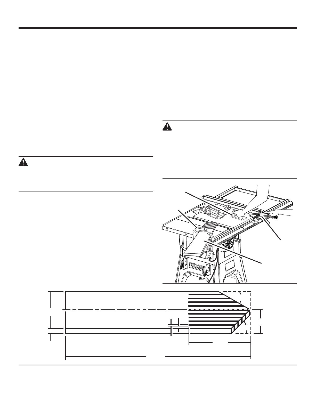
OPERATION
To make a jig:
Attach a handle to a long, straight piece of wood and
secure from the underside using recessed screws.
Cut an L-shaped stop in the side of the jig.
To use a jig:
Position the workpiece flat on the table with the edge
flush against the jig and against the stop.
Holding the jig handle and using a push block and/or push
stick, make the rip cut as described later in this section.
FEATHERBOARD
A featherboard is a device used to help control the
workpiece by holding it securely against the table or fence.
Featherboards are especially useful when ripping small
workpieces and for completing non-through cuts. The end
is angled with a number of short kerfs to give a friction hold
on the workpiece and locked in place on the table with a
C-clamp. Test that it can resist kickback.
WARNING:
Place the featherboard against the uncut portion of
the workpiece to avoid kickback that could cause
serious personal injury.
completely stop rotating before removing the stock. Reset
the rip fence and cut spaced rips into the workpiece to allow
approximately 1/4 in. fingers and 1/8 in. spaces between
the fingers.
HOW TO MOUNT A FEATHERBOARD
See Figure 45.
Completely lower the saw blade. Position the rip fence to the
desired adjustment for the cut to be performed and lock the
rip fence. Place the workpiece against the fence and over the
saw blade area. Adjust the featherboard to apply resistance
to the workpiece just forward of the blade. Attach C-clamps
to secure the featherboard to the edge of the saw table.
WARNING:
The featherboard must be installed in front of
the blade. Do not locate the featherboard to the
rear of the blade. Kickback can result from the
featherboard pinching the workpiece and binding
the blade in the saw kerf if positioned improperly.
Failure to heed this warning can result in serious
personal injury.
PUSH BLOCK
HOW TO MAKE A FEATHERBOARD
See Figure 44.
The featherboard is an excellent project for your saw. Select
a solid piece of lumber approximately 3/4 in. thick, 3-5/8 in.
wide and 18 in. long. Mark the center of the width on one end
of the stock. Miter one-half of the width to 30° and miter the
other half of the same end to 45° (see page 38 for information
on miter cuts). Mark the board from the point at six inches.
Prepare the saw for ripping as discussed on page 38. Set
the rip fence to allow approximately a 1/4 in. “finger” to be
cut in the stock. Feed the stock only to the mark previously
made at 6 in. Turn the saw OFF and allow the blade to
3-5/8 in.
3/4 in.
C-CLAMP
1/4 in.
1/8 in.
PUSH
STICK
FEATHERBOARD
Fig. 45
30°
1-13/16 in.
45°
6 in.
18 in.
31 - English
Find Quality Products Online at: [email protected]
www.GlobalTestSupply.com
Fig. 44
Page 32
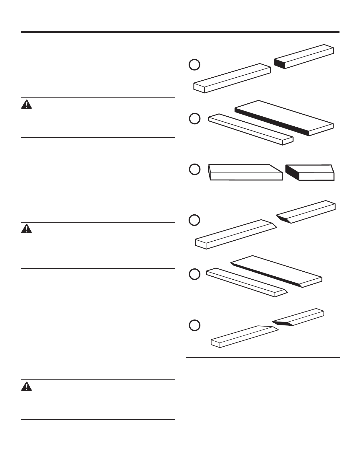
OPERATION
TYPES OF CUTS
See Figure 46.
There are six basic cuts: 1) the cross cut, 2) the rip cut, 3)
the miter cut, 4) the bevel cross cut, 5) the bevel rip cut,
and 6) the compound (bevel) miter cut. All other cuts are
combinations of these basic six. Operating procedures for
making each kind of cut are given later in this section.
WARNING:
Always make sure the blade guard and antikickback pawls are in place and working properly
when making these cuts to avoid possible injury.
1
CROSS CUT
2
Cross cuts are straight 90° cuts made across the grain of
the workpiece. The wood is fed into the cut at a 90° angle
to the blade, and the blade is vertical.
Rip cuts are made with the grain of the wood. To avoid
kickback while making a rip cut, make sure one side of the
wood rides firmly against the rip fence.
Miter cuts are made with the wood at any angle to the
blade other than 90°. The blade is vertical. Miter cuts tend
to “creep” during cutting. This can be controlled by holding
the workpiece securely against the miter gauge.
WARNING:
Always use a push stick with small pieces of wood,
and also to finish the cut when ripping a long
narrow piece of wood, to prevent your hands from
getting close to the blade.
Bevel cuts are made with an angled blade. Bevel cross cuts
are across the wood grain, and bevel rip cuts are with the
grain. The rip fence must always be on the right side of the
blade for bevel rip cuts.
Compound (or bevel) miter cuts are made with an angled
blade on wood that is angled to the blade. Be thoroughly
familiar with making cross cuts, rip cuts, bevel cuts, and
miter cuts before trying a compound miter cut.
RIP CUT
3
MITER CUT
4
BEVEL CROSS CUT
5
BEVEL RIP CUT
6
CUTTING TIPS
Dado and rabbet cuts are non-through cuts which can be
either rip cuts or cross cuts. Carefully read and understand
all sections of this operator’s manual before attempting any
operation.
WARNING:
Do not use blades rated less than the speed of
this tool. Failure to heed this warning could result
in personal injury.
32 - English
Find Quality Products Online at: [email protected]
www.GlobalTestSupply.com
The kerf (the cut made by the blade in the wood) will be
wider than the blade to avoid overheating or binding.
Make allowance for the kerf when measuring wood.
Make sure the kerf is made on the waste side of the
measuring line.
Cut the wood with the finish side up.
Knock out any loose knots with a hammer before making
the cut.
Always provide proper support for the wood as it comes
out of the saw.
COMPOUND (BEVEL) MITER CUT
Fig. 46
Page 33
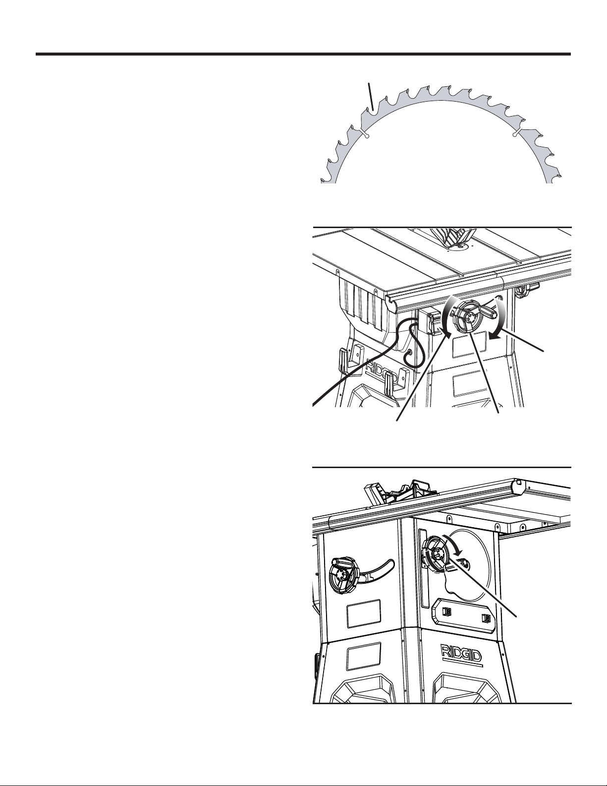
OPERATION
HEIGHT ADJUSTING AND BEVEL ADJUSTING
HANDWHEEL KNOBS
The height adjusting handwheel knob and bevel adjusting
handwheel knobs act as locks. To unlock either knob before
making an adjustment, turn the knob counterclockwise to
loosen. After making a height or bevel adjustment, turn the
knob clockwise to tighten.
TO CHANGE BLADE DEPTH
See Figures 47 - 48.
The blade depth should be set so that the outer points of the
saw blade are higher than the workpiece by approximately
1/8 in. to 1/4 in. but the lowest points (gullets) are below
the top surface.
Raise the blade by unlocking the height adjusting
handwheel and turning it clockwise.
Lower the blade by unlocking the height adjusting
handwheel and turning it counterclockwise.
TO CHANGE BLADE ANGLE
See Figure 49.
NOTE: A 90° cut has a 0° bevel and a 45° cut has a 45° bevel.
Unplug the saw.
Unlock the bevel adjusting handwheel by rotating the
locking knob counterclockwise.
Adjust the bevel angle by turning the bevel adjusting
handwheel. Turning the handwheel clockwise will tilt the
saw blade to the left.
When the saw blade is tilted to the left as far as it will go,
the blade should be at a 45° angle to the saw table and
the bevel indicator should point to 45°.
When the saw blade is tilted to the right as far as it will
go, the blade should be at 90° to the saw table and the
bevel indicator should point to 0°.
NOTE: When the saw blade is 90° to the saw table, the
saw blade should be square with the saw table. (See the
Adjustments section of this manual to square the saw
blade.)
GULLET
TO LOWER
Fig. 47
TO
RAISE
HEIGHT
ADJUSTING
HANDWHEEL
Fig. 48
BEVEL
ADJUSTING
HANDWHEEL
Fig. 49
33 - English
Find Quality Products Online at: [email protected]
www.GlobalTestSupply.com
Page 34
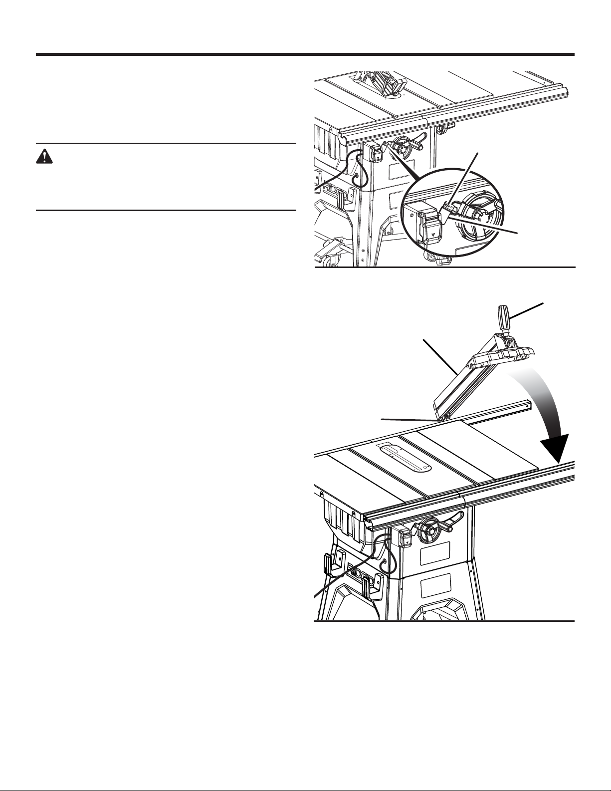
OPERATION
TO ADJUST THE BEVEL INDICATOR
See Figure 50.
If the bevel indicator is not at zero when the saw blade is at
0°, adjust the indicator by loosening the screw and setting
it at 0° on the bevel scale. Retighten the screw.
WARNING:
To reduce the risk of injury, always make sure the
rip fence is parallel to the blade before beginning
any operation.
SCREW
TO USE THE RIP FENCE
See Figure 51.
Loosen the rip fence by lifting the locking handle.
Place the rear lip on the rear of the saw table and pull
slightly toward the front of the unit.
Lower the front end of the rip fence onto the guide surfaces
on top of the front rail.
With the rip fence flat on the saw table, push the fence
towards the front rail to align the fence to the saw table.
Push the locking handle down to secure the fence.
Check for a smooth gliding action. If adjustments are needed,
see To Check the Alignment of the Rip Fence to the Blade
in the Adjustment section of this manual.
Make two or three test cuts on scrap wood. If the cuts
are not true, repeat the process.
NOTE: The rip fence must be secure when the locking handle
is engaged. To increase the grip of the rip fence on the rear
lip of the table, tighten the clamp screw on the rear of the
rip fence by turning it clockwise. Adjust if needed.
BEVEL
INDICATOR
Fig. 50
LOCKING
HANDLE
RIP
FENCE
REAR
LIP
Fig. 51
34 - English
Find Quality Products Online at: [email protected]
www.GlobalTestSupply.com
Page 35
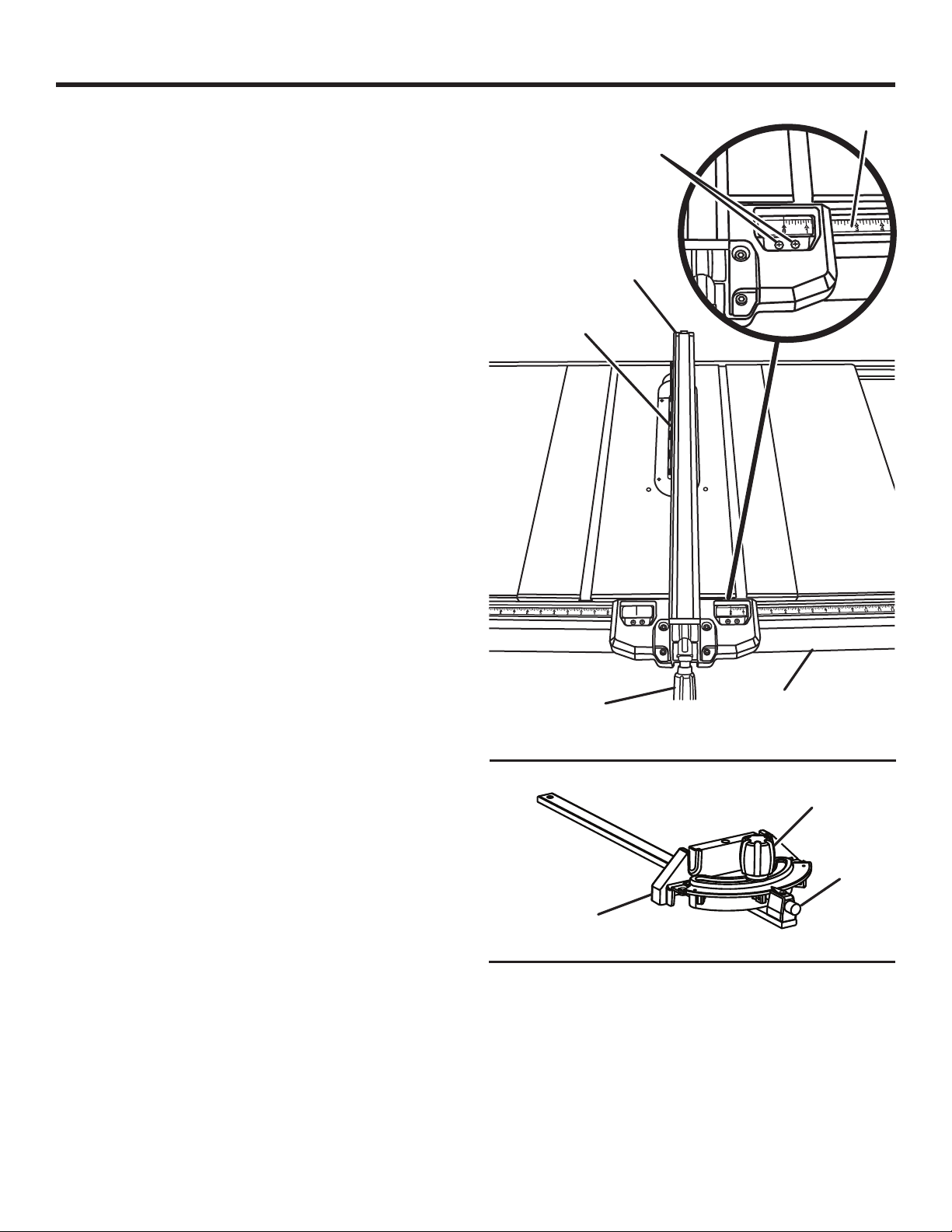
OPERATION
TO SET THE RIP FENCE SCALE INDICATOR
TO THE BLADE
See Figure 52.
Use the indicator on the rip fence to position the fence along
the scale on the front rail.
NOTE: The anti-kickback pawls and blade guard assembly
must be removed to perform this adjustment. Reinstall the
blade guard assembly when the adjustment is complete.
Begin with the blade at a zero angle (straight up).
Unplug the saw.
Loosen the rip fence by lifting the locking handle.
Set the rip fence gently against the blade tip edge.
Loosen the screw on the scale indicator and align with
the 0 mark as shown.
Tighten the screw and check the dimension and the rip
fence.
Repeat this adjustment on the other side of the blade.
TO USE THE MITER GAUGE
See Figure 53.
The miter gauge provides greater accuracy in angled cuts.
For very close tolerances, test cuts are recommended.
There are two miter gauge grooves, one on either side of
the blade. When making a 90° cross cut, you can use either
miter gauge groove. When making a beveled cross cut (the
blade tilted in relation to the table) the miter gauge should
be located in the slot on the right so that the blade is tilted
away from the miter gauge and your hands.
The miter gauge can be turned 60° to the right or left.
Slide the miter gauge in the miter gauge slot.
Loosen the lock knob by turning it counterclockwise.
Pull out the stop pin and rotate the gauge until the desired
angle is reached on the scale.
Retighten the lock knob by turning it clockwise.
BLADE
LOCKING
HANDLE
SCALE
SCREW
RIP
FENCE
FRONT
RAIL
Fig. 52
LOCK
KNOB
STOP
PIN
MITER
GAUGE
35 - English
Find Quality Products Online at: [email protected]
www.GlobalTestSupply.com
Fig. 53
Page 36
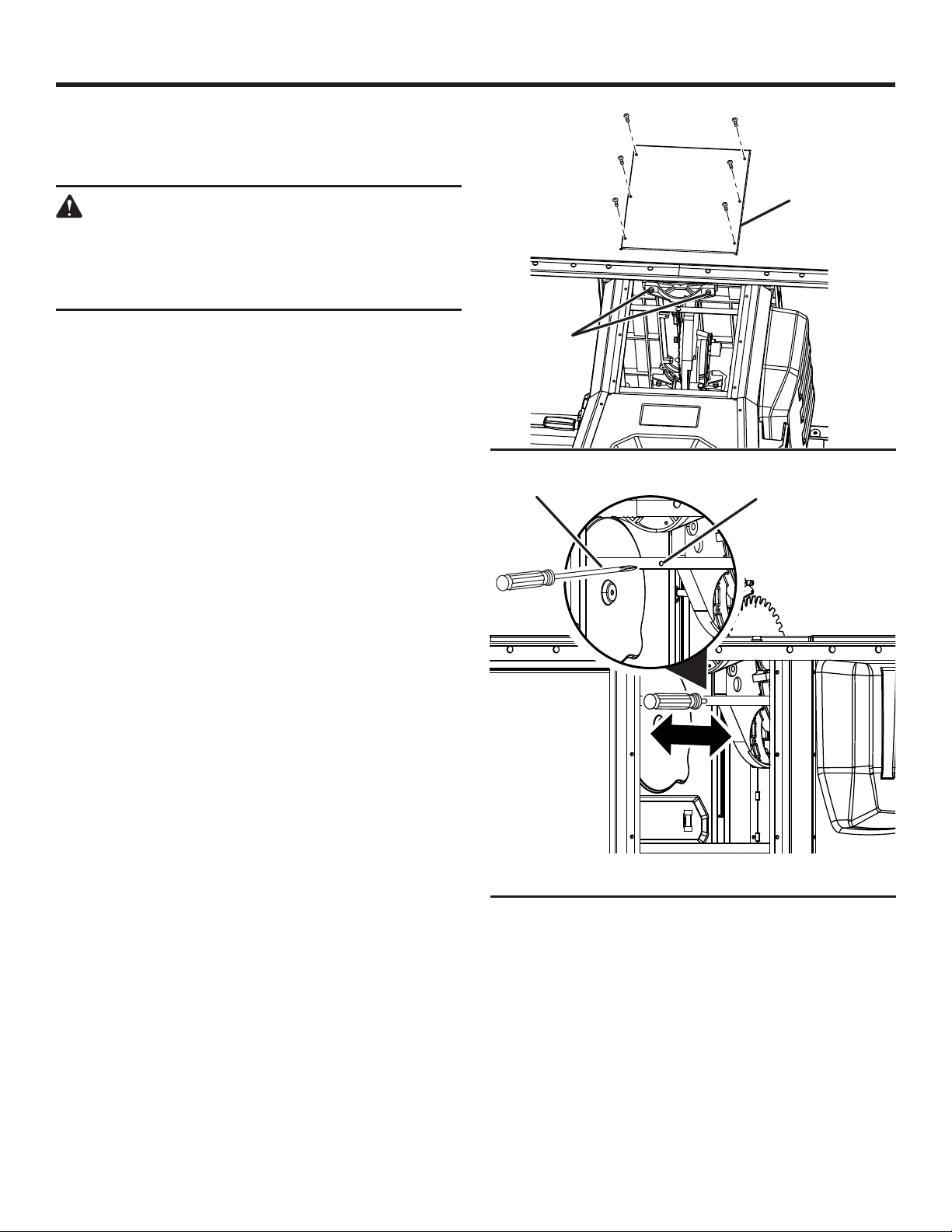
OPERATION
ADJUSTING THE BLADE PARALLEL TO THE
MITER GAUGE GROOVE (REMOVING HEEL)
See Figures 54 - 57.
WARNING:
The blade must be made parallel to the miter
gauge groove so the wood does not bind
resulting in kickback. Failure to do so could result
in serious personal injury.
REAR PANEL
Do not loosen any bolts for this adjustment until you have
checked with a square and made test cuts to be sure
adjustments are necessary. Once the bolts are loosened,
these items must be reset.
Unplug the saw.
With a 4 mm wrench, remove the 6 screws that secure
the rear panel of the saw. Remove the panel.
Remove the blade guard, riving knife, and anti-kickback
pawls. Raise the blade by unlocking the height adjusting
handwheel and turning it clockwise.
Mark beside one of the blade teeth at the front of the
blade. Using a ruler, measure the distance from the inside
face of the blade tooth to the left edge of the right miter
gauge groove.
NOTE: For greater accuracy, place the marked blade
tooth on top of the ruler.
Turn the blade so the marked tooth is at the back.
Move the ruler to the rear and again measure the distance
from the inside face of the blade tooth to the left edge
of the right miter gauge groove. If the distances are the
same, the blade and the miter gauge groove are parallel.
Replace blade guard, riving knife, and anti-kickback pawls.
If the distances are different:
Remove the blade guard, riving knife, and anti-kickback
pawls. Raise the blade by unlocking the height adjusting
handwheel and turning it clockwise.
Loosen the two adjusting bolts.
NOTE: The adjusting bolts are located under the saw
table.
Insert a screwdriver into the hole located at the rear of the
saw as shown in figure 55. Use the screwdriver to move
the motor and blade assembly to the left or the right.
ADJUSTING
BOLTS (2)
SCREWDRIVER
Fig. 54
HOLE
Fig. 55
36 - English
Find Quality Products Online at: [email protected]
www.GlobalTestSupply.com
Page 37
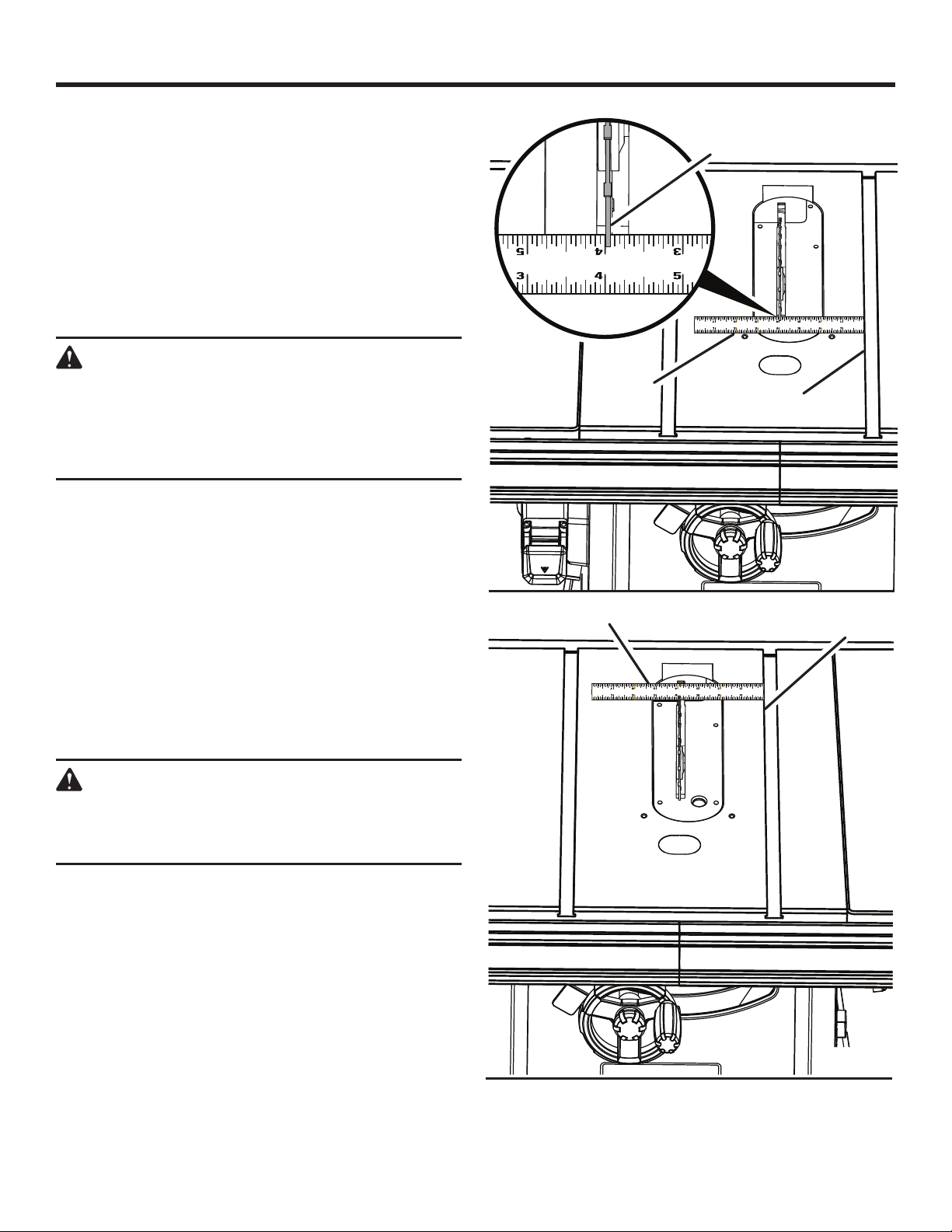
OPERATION
If the back of the blade was too far from the miter gauge
groove, move the motor and blade assembly to the right
(away from the blade and wrench storage area) until the
blade is square. Retighten the bolts.
If the back of the blade was too close to the miter gauge
groove, move the motor and blade assembly to the left
(toward the blade and wrench storage area) until the blade
is square. Retighten the bolts.
After all bolts have been retightened, ensure that the blade
is aligned by verifying that the distance at the front and
rear of the blade are the same.
WARNING:
To reduce the risk of injury from kickback, align
the rip fence to the blade following any blade
adjustments. Always make sure the rip fence
is parallel to the blade before beginning any
operation.
MAKING CUTS
This table saw can perform a variety of cuts that are not all
mentioned in this manual. DO NOT attempt to make any cuts
not covered here unless you are thoroughly familiar with the
proper procedures and necessary accessories. Your local
library has many books on table saw usage and specialized
woodworking procedures for your reference.
The blade provided with the saw is a high-quality combination
blade suitable for ripping and cross cut operations. Carefully
check all setups and rotate the blade one full revolution to
assure proper clearance before connecting saw to power
source. Stand slightly to the side of the blade path to reduce
the chance of injury should kickback occur.
RULER
RULER
BLADE
TOOTH
MITER GAUGE
GROOVE
Fig. 56
MITER GAUGE
GROOVE
WARNING:
Do not use blades rated less than the speed of
this tool. Failure to heed this warning could result
in personal injury.
Fig. 57
37 - English
Find Quality Products Online at: [email protected]
www.GlobalTestSupply.com
Page 38
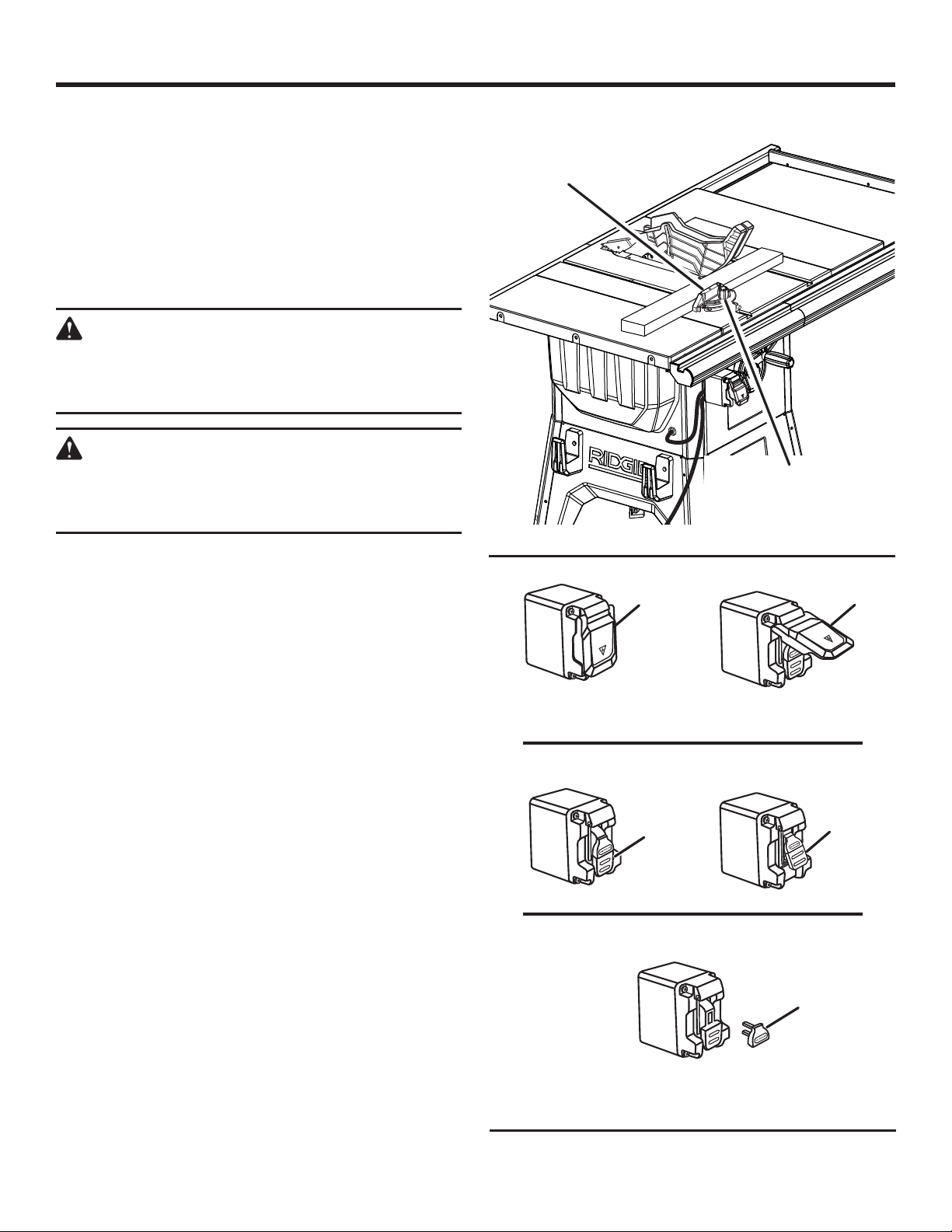
OPERATION
Use the miter gauge when making cross, miter, bevel, and
compound miter cuts. To secure the angle, lock the miter
gauge in place by twisting the lock knob clockwise. Always
tighten the lock knob securely in place before use.
NOTE: It is recommended that you place the piece to be
saved on the same side of the blade as the miter gauge, and
that you make a test cut on scrap wood first.
TO MAKE A CROSS CUT
See Figures 58 - 59.
WARNING:
Make sure the blade guard assembly is installed
and working properly to avoid serious possible
injury.
WARNING:
Using the rip fence as a cutoff gauge when cross
cutting will result in kickback which can cause
serious personal injury.
Remove the rip fence.
Set the blade to the correct depth for the workpiece.
Set the miter gauge to 0° and tighten the lock knob.
Make sure the wood is clear of the blade before turning
on the saw.
To turn the saw ON, lift the switch.
NOTE: This saw has a switch cover. Raise the cover to
access the switch.
To turn saw OFF, press the switch down.
NOTE: To prevent unauthorized use, remove the switch
key as shown in figure 59.
Let the blade build up to full speed before moving the
workpiece into the blade.
Hold the workpiece firmly with both hands on the miter
gauge and feed the workpiece into the blade.
NOTE: The hand closest to the blade should be placed
on the miter gauge lock knob and the hand farthest from
the blade should be placed on the workpiece.
When the cut is made, turn the saw off. Wait for the
blade to come to a complete stop before removing the
workpiece.
PLACE LEFT HAND ON
WORKPIECE AND
MITER GAUGE HERE
SWITCH
COVER
NOTE: For clarity, the cover is not shown
in the illustrations below.
SWITCH OFF
SWITCH
SWITCH IN LOCKED POSITION
CROSS CUT
PLACE RIGHT HAND
ON MITER GAUGE
LOCK KNOB
SWITCH
ON
SWITCH
SWITCH KEY
REMOVED
Fig. 58
SWITCH
COVER
NOTE: The cover does not need to be removed
to remove the switch key.
38 - English
Find Quality Products Online at: [email protected]
www.GlobalTestSupply.com
Fig. 59
Page 39

OPERATION
MAKING A RIP CUT
See Figure 60.
WARNING:
Make sure the blade guard assembly is installed
and working properly to avoid serious possible
injury.
WARNING:
Taper cuts must only be made with a special jig,
which is commercially available. Do not attempt
a freehand taper cut on this saw. Failure to follow
these instructions could result in serious personal
injury.
Set the blade to the correct depth for the workpiece.
Position the rip fence the desired distance from the blade
for the cut and securely lock the handle.
When ripping a long workpiece, place a support the same
height as the table surface behind the saw for the cut
work.
Install feather board in the appropriate position for the
cut being made.
Make sure the wood is clear of the blade before turning
on the saw.
RIP
FENCE
BLADE
MITER GAUGE
ANGLED
RIP CUT
SCALE
Fig. 60
MITER CUT
BLADE
STRAIGHT
Turn the saw on.
Position the workpiece flat on the table with the edge
flush against the rip fence. Let the blade build up to full
speed before feeding the workpiece into the blade.
Using a push stick and/or push blocks, slowly feed the
workpiece toward the blade. Stand slightly to the side of
the wood as it contacts the blade to reduce the chance
of injury should kickback occur.
Once the blade has made contact with the workpiece, use
the hand closest to the rip fence to guide it. Make sure
the edge of the workpiece remains in solid contact with
both the rip fence and the surface of the table. If ripping
a narrow piece, use a push stick and/or push blocks to
move the piece through the cut and past the blade.
When the cut is made, turn the saw off. Wait for the
blade to come to a complete stop before removing the
workpiece.
MAKING A MITER CUT
See Figure 61.
WARNING:
Make sure the blade guard assembly is installed
and working properly to avoid possible serious
injury.
HEIGHT
ADJUSTING
HANDWHEEL
Fig. 61
Set the blade to the correct depth for the workpiece.
Remove the rip fence.
Set the miter gauge to the desired angle and tighten the
lock knob.
Make sure the wood is clear of the blade before turning
on the saw.
Turn the saw on.
Let the blade build up to full speed before moving the
workpiece into the blade.
Hold the workpiece firmly with both hands on the miter
gauge and feed the workpiece into the blade.
39 - English
Find Quality Products Online at: [email protected]
www.GlobalTestSupply.com
Page 40
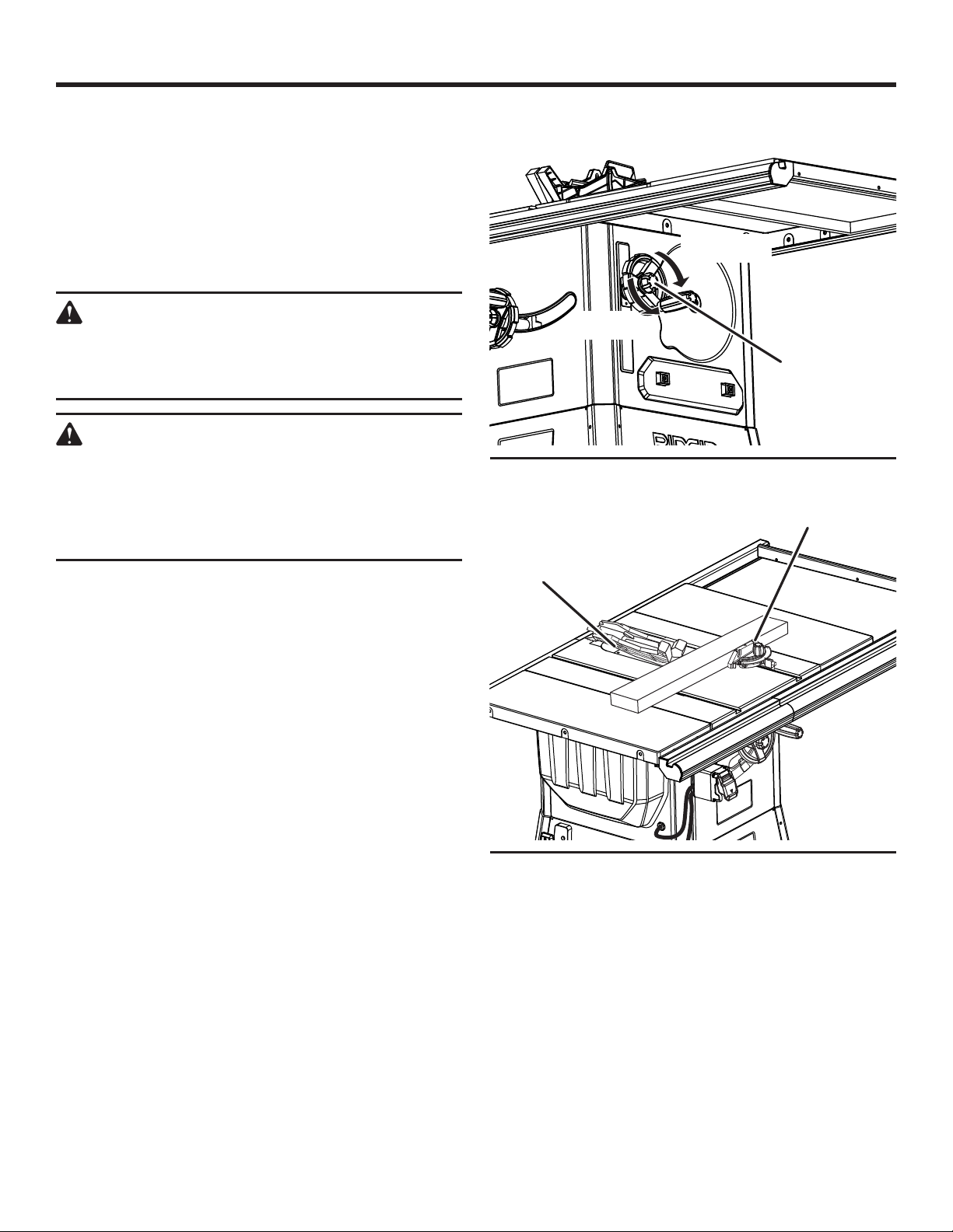
OPERATION
NOTE: The hand closest to the blade should be placed
on the miter gauge lock knob and the hand farthest from
the blade should be placed on the workpiece.
When the cut is made, turn the saw off. Wait for the
blade to come to a complete stop before removing the
workpiece.
MAKING A BEVEL CROSS CUT
See Figures 62 - 63.
WARNING:
Make sure the blade guard assembly is installed
and working properly to avoid serious personal
injury.
WARNING:
The miter gauge must be on the right side of the
blade to avoid trapping the wood and causing
kickback. Placement of the miter gauge to the
left of the blade will result in kickback and the
risk of serious personal injury.
Remove the rip fence.
Unlock the bevel lock knob.
Adjust the bevel angle to the desired setting.
Lock the bevel lock knob.
Set the blade to the correct depth for the workpiece.
Set the miter gauge to 0° and tighten the lock knob.
Make sure the wood is clear of the blade before turning
on the saw.
Turn the saw on.
Let the blade build up to full speed before moving the
workpiece into the blade.
Hold the workpiece firmly with both hands on the miter
gauge and feed the workpiece into the blade.
NOTE: The hand closest to the blade should be placed
on the miter gauge lock knob and the hand farthest from
the blade should be placed on the workpiece.
When the cut is made, turn the saw off. Wait for the
blade to come to a complete stop before removing the
workpiece.
VIEWED FROM THE SIDE, BELOW THE TABLE SAW
TO UNLOCK
TO LOCK
BEVEL LOCK
KNOB
Fig. 62
BEVEL CROSS CUT
MITER GAUGE
STRAIGHT
BLADE
ANGLED
Fig. 63
40 - English
Find Quality Products Online at: [email protected]
www.GlobalTestSupply.com
Page 41
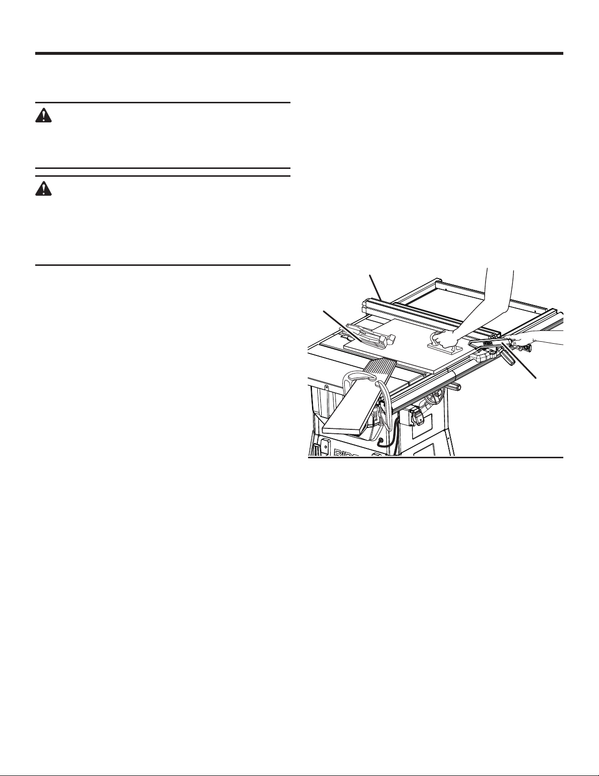
OPERATION
MAKING A BEVEL RIP CUT
See Figure 64.
WARNING:
Make sure the blade guard assembly is installed
and working properly to avoid serious personal
injury.
WARNING:
The rip fence must be on the right side of the
blade to avoid trapping the wood and causing
kickback. Placement of the rip fence to the left
of the blade will result in kickback and the risk
of serious personal injury.
Remove the miter gauge.
Install feather board in the appropriate position for the
cut being made.
Unlock the bevel lock knob.
Adjust the bevel angle to the desired setting.
Lock the bevel lock knob.
Set the blade to the correct depth for the workpiece.
Position the rip fence the desired distance from the blade
for the cut and securely lock the handle.
Make sure the wood is clear of the blade before turning
on the saw.
When ripping a long workpiece, place a support the same
height as the table surface behind the saw for the cut
work.
Turn the saw on.
Position the workpiece flat on the table with the edge
flush against the rip fence. Let the blade build up to full
speed before feeding the workpiece into the blade.
Using a push stick and/or push blocks, slowly feed the
workpiece toward the blade. Stand slightly to the side of
the wood as it contacts the blade to reduce the chance
of injury should kickback occur.
Once the blade has made contact with the workpiece, use
the hand closest to the rip fence to guide it. Make sure
the edge of the workpiece remains in solid contact with
both the rip fence and the surface of the table. If ripping
a narrow piece, use a push stick and/or push blocks to
move the piece through the cut and past the blade.
When the cut is made, turn the saw off. Wait for the
blade to come to a complete stop before removing the
workpiece.
BEVEL RIP CUT
RIP FENCE
BLADE
ANGLED
PUSH
STICK
Fig. 64
41 - English
Find Quality Products Online at: [email protected]
www.GlobalTestSupply.com
Page 42
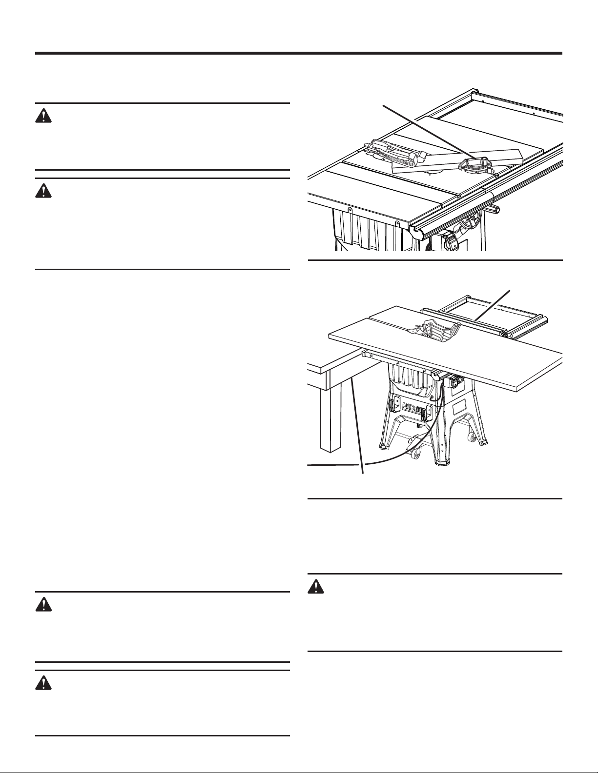
OPERATION
MAKING A COMPOUND (BEVEL) MITER CUT
See Figure 65.
WARNING:
Make sure the blade guard assembly is installed
and working properly to avoid possible serious
injury.
WARNING:
The miter gauge must be on the right side of the
blade to avoid trapping the wood and causing
kickback. Placement of the miter gauge to the
left of the blade will result in kickback and the
risk of serious personal injury.
Remove the rip fence.
Unlock the bevel lock knob.
Adjust the bevel angle to the desired setting.
Lock the bevel lock knob.
Set the blade to the correct depth for the workpiece.
Set the miter gauge to the desired angle and tighten the
lock knob.
Make sure the wood is clear of the blade before turning
on the saw.
Turn the saw on.
Let the blade build up to full speed before moving the
workpiece into the blade.
Hold the workpiece firmly with both hands on the miter
gauge and feed the workpiece into the blade.
NOTE: The hand closest to the blade should be placed
on the miter gauge lock knob and the hand farthest from
the blade should be placed on the workpiece.
When the cut is made, turn the saw off. Wait for the
blade to come to a complete stop before removing the
workpiece.
MAKING A LARGE PANEL CUT
See Figure 66.
Make sure the saw is properly secured and the leg stand is
lowered (feet on the floor) to avoid tipping from the weight
of a large panel.
WARNING:
Make sure the blade guard assembly is installed
and working properly to avoid possible serious
injury.
WARNING:
Never make freehand cuts (cuts without the miter
gauge or rip fence), which can result in serious
injury.
COMPOUND (BEVEL) MITER CUT
PLACE LEFT HAND ON
MITER GAUGE HERE
Fig. 65
LARGE PANEL CUT
RIP FENCE
SUPPORTS
Install feather board in the appropriate position for the
cut being made.
Place a support the same height as the top of the saw
table behind the saw for the cut work. Add supports to
the sides as needed.
Fig. 66
WARNING:
Improper support of the workpiece on the side
and/or outfeed side of the saw could create
unexpected movement of the workpiece and/
or the saw, resulting in serious personal injury.
Depending on the shape of the panel, use the rip fence
or miter gauge. If the panel is too large to use either the
rip fence or the miter gauge, it is too large for this saw.
Make sure the wood does not touch the blade before you
turn on the saw.
Turn the saw on.
42 - English
Find Quality Products Online at: [email protected]
www.GlobalTestSupply.com
Page 43
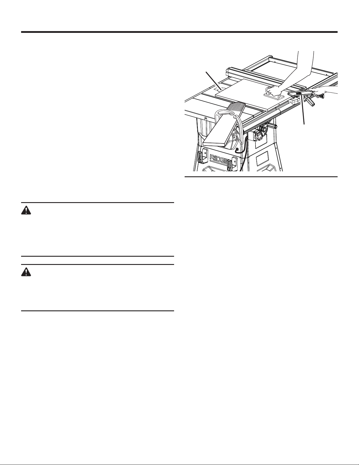
OPERATION
Position the workpiece flat on the table with the edge
flush against the rip fence. Let the blade build up to full
speed before feeding the workpiece into the blade.
Use a push stick and/or push blocks to move the piece
through the cut and past the blade.
When the cut is made, turn the saw off. Wait for the
blade to come to a complete stop before removing the
workpiece.
MAKING A NON-THROUGH CUT
See Figure 67.
Non-through cuts (made with a standard 10 in. blade) can be
made with the grain (ripping) or across the grain (cross cut).
The use of a non-through cut is essential to cutting grooves,
rabbets, and dadoes. This is the only type cut that is made
without the blade guard assembly installed. Make sure the
blade guard assembly is reinstalled upon completion of this
type of cut. Read the appropriate section which describes
the type of cut in addition to this section on non-through or
dado cuts. For example, if your non-through cut is a straight
cross cut, read and understand the section on straight cross
cuts before proceeding.
WARNING:
When making a non-through cut, the blade is
covered by the workpiece during most of the cut.
Be alert to the exposed blade at the start and
finish of every cut to reduce the risk of personal
injury.
WARNING:
Never feed wood with your hands when making
any non-through cut such as rabbets or dadoes.
To avoid personal injury, always use push blocks,
push sticks, and featherboards.
NON-THROUGH CUT
BLADE
GUARD
REMOVED
PUSH
STICK
Fig. 67
Unplug the saw.
Remove the blade guard and anti-kickback pawls.
Place riving knife in “down” position.
Unlock the bevel lock knob.
Adjust the bevel angle to the desired setting.
Lock the bevel lock knob.
Set the blade to the correct depth for the workpiece.
Depending on the shape and size of the wood, use either
the rip fence or miter gauge.
Plug the saw into the power source and turn the saw on.
Let the blade build up to full speed before moving the
workpiece into the blade.
Always use push blocks, push sticks, and/or featherboards
appropriately when making non-through cuts to reduce
the risk of serious injury.
When the cut is made, turn the saw off. Wait for the
blade to come to a complete stop before removing the
workpiece.
43 - English
Find Quality Products Online at: [email protected]
www.GlobalTestSupply.com
Page 44
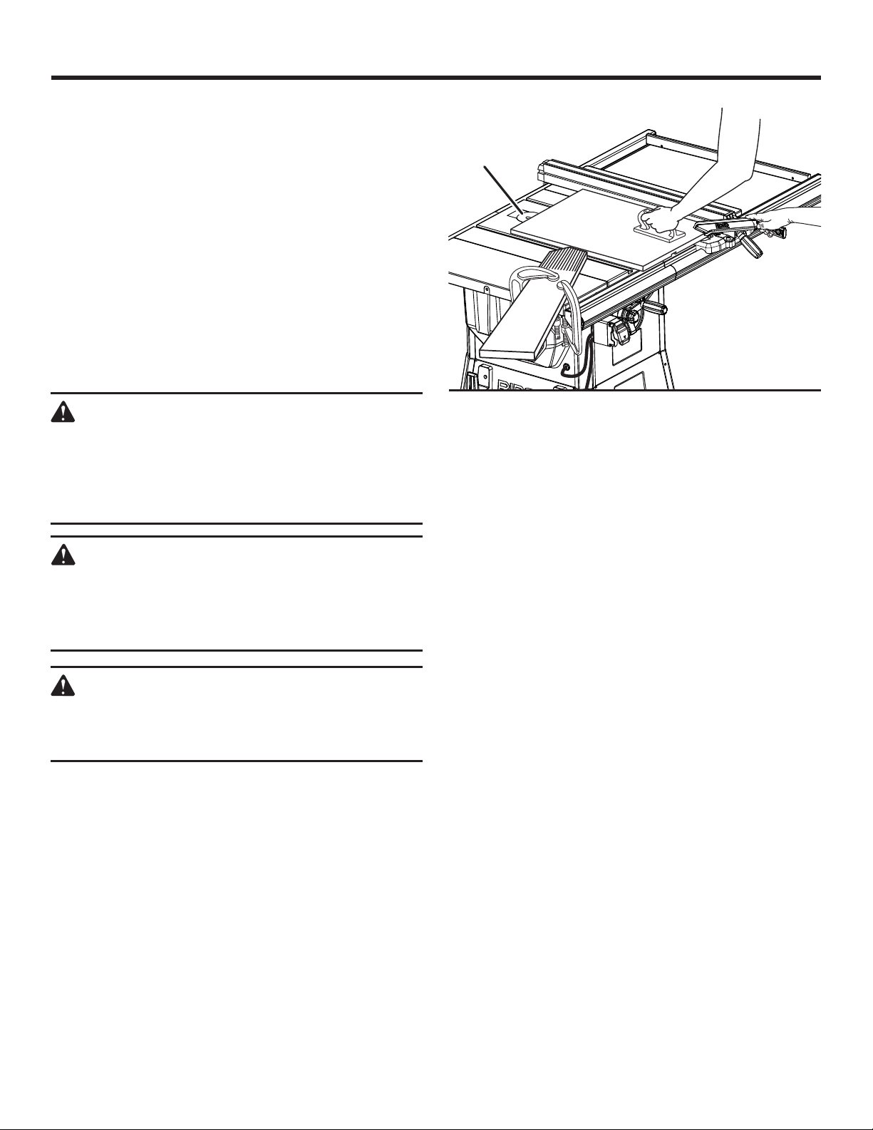
OPERATION
Once all non-through cuts are completed:
Unplug your saw.
Reinstall the riving knife in the “up” position then install
blade guard and anti-kickback pawls.
MAKING A DADO CUT
See Figure 68.
An optional dado throat plate is required for this procedure
(see the Accessories section of this manual and check with
the retailer where the table saw was purchased). All blades
and dado sets must not be rated less than the speed of this
tool. This saw is designed for use with an up to 8 in. stack
dado (up to width of 13/16 in., with a maximum depth of
cut of 1-1/2 in.). Do not use an adjustable dado on this saw.
NOTE: Do not set beyond 1-1/2 in. Ensure that the release
lever is not raising the throat plate.
WARNING:
When making a non-through cut, the blade is
covered by the workpiece during most of the cut.
Be alert to the exposed blade at the start and
finish of every cut to reduce the risk of personal
injury.
WARNING:
Always put all blade washers, spacers, and nuts
in proper location when changing back to saw
blade. Failure to do so can result in possible injury
and damage to the tool.
WARNING:
Always use push blocks, push sticks, and/or
featherboards when making dado cuts to avoid
the risk of serious injury.
Unplug your saw.
Remove the blade guard, anti-kickback pawls, throat
plate, and riving knife.
Remove the blade nut, outer blade washer, saw blade,
inner blade washer, and spacer.
NOTE: Always store the blade washer and throat plate
in a secure location.
Reinstall the inner blade washer.
Mount the dado blade, according to manufacturer
instructions, using the blade and chippers appropriate
for the desired width of cut.
DADO CUT
BLADE
GUARD
REMOVED
Fig. 68
Reinstall the blade nut.
NOTE: The blade washer may be used provided the arbor
shaft extends slightly beyond the arbor nut.
Make sure the blade nut is fully engaged and the arbor
extends past a securely tightened blade nut.
Place riving knife release lever in locked position.
Install the dado throat plate and rotate the blade by hand
to make sure it turns freely then lower the blade.
Set the blade height.
Depending on the shape and size of the wood, use either
the rip fence or miter gauge.
NOTE: If you cannot use either the rip fence or miter
gauge, you cannot make a dado cut with this saw.
If making a rip cut, install feather board in the appropriate
position for the cut being made.
Turn the saw on.
NOTE: Make sure the wood does not touch the blade
before you turn on the saw. Let the blade build up to full
speed before feeding the workpiece into the blade.
Position the workpiece flat on the table with the edge
flush against the rip fence or miter gauge.
Use a push block or push stick to move the wood through
the cut past the blade. Never push a small piece of wood
into the blade with your hand, always use a push stick.
The use of push blocks, push sticks, and featherboards
are necessary when making non-through cuts.
When the cut is made, turn the saw off. Wait for the
blade to come to a complete stop before removing the
workpiece.
44 - English
Find Quality Products Online at: [email protected]
www.GlobalTestSupply.com
Page 45
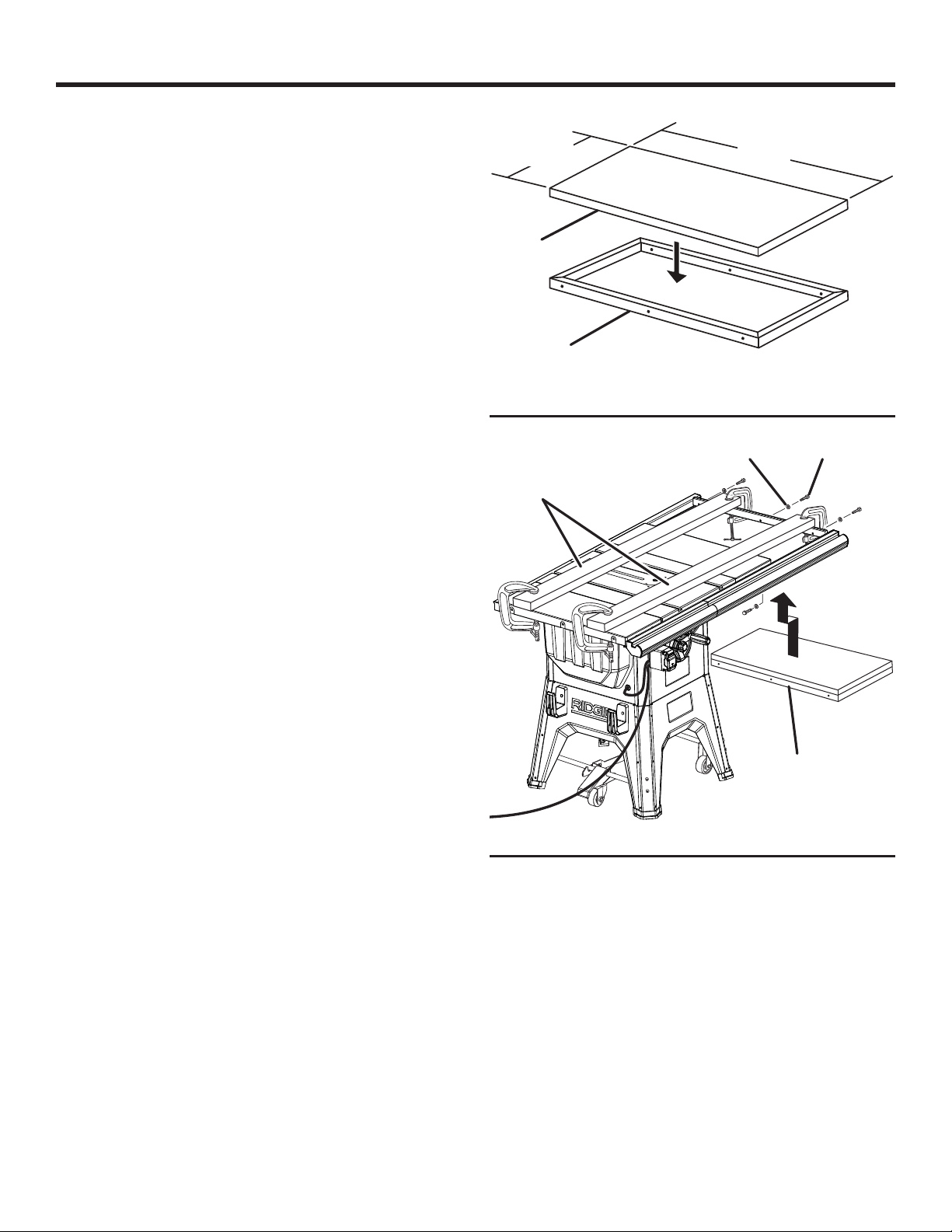
OPERATION
Once all dado cuts are completed:
Unplug your saw.
Remove the dado blade and reinstall the standard cutting
blade.
Reinstall the riving knife in the “up” position then install
the blade guard and anti-kickback pawls.
14-5/8 in.
27 in.
CONSTRUCTING A TABLE EXTENSION
See Figure 69.
You may construct a wood table extension to support larger
workpieces.
The finished height of the table extension should be
1-3/4 in. The finished length and width should be
27 in. x 14-5/8 in.
Assemble the pieces as shown. The finished extension
should fit snugly into the rails, and should be level with
the saw table and extensions.
TO INSTALL THE TABLE EXTENSION ONTO THE
RAILS
See Figure 70.
Make sure that when you install the table extension onto
the rails, it is level with the rest of the saw table. To do this,
use two 2 x 4 boards that are 55-1/2 in. in length. Securely
clamp the boards to the end of the saw table, and to the
spreader bar.
Insert the table extension from underneath the rails and
set it into position.
Make sure the extension lies flat and is aligned with the
rest of the saw table. There should be no space between
the extension and the boards.
There are holes in the spreader bar. Attach the extension
to the saw with pan head phillips screws and supplied
washers as shown.
3/4 in.
1 in. x 2 in.
Fig. 69
SCREWWASHER
2 in. x 4 in. BOARD
TABLE
EXTENSION
Fig. 70
45 - English
Find Quality Products Online at: [email protected]
www.GlobalTestSupply.com
Page 46
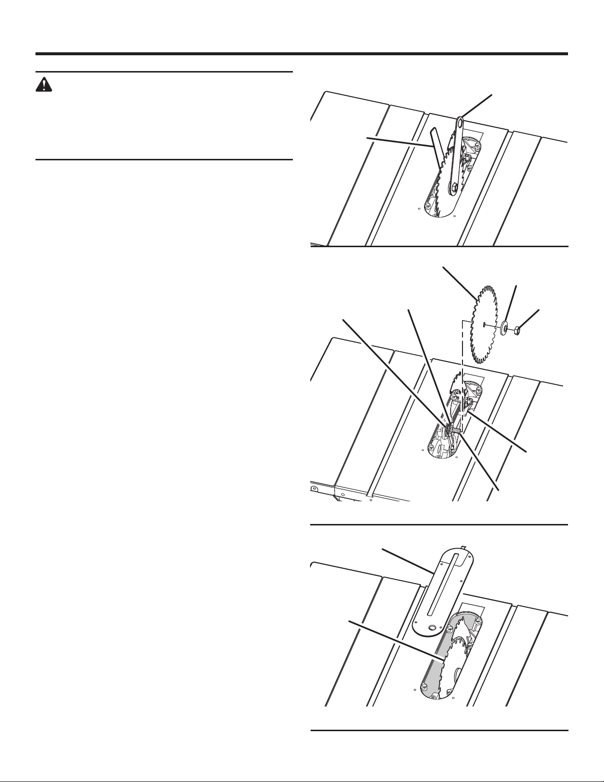
ADJUSTMENTS
CLOSED END
WARNING:
Before performing any adjustment, make sure
the tool is unplugged from the power supply and
the switch is in the OFF ( O ) position. Failure to
heed this warning could result in serious personal
injury.
To avoid unnecessary set-ups and adjustments, a good
practice is to check your setups carefully with a framing
square and make practice cuts in scrap wood before making
finish cuts in good workpieces. Do not start any adjustments
until you have checked with a square and made test cuts to
be sure adjustments are needed.
TO REPLACE THE BLADE
See Figures 71 - 73.
Blade kerf width must be within the limits stamped on the
riving knife.
Unplug the saw.
Lower the saw blade and remove the throat plate.
Raise the saw blade to full height then remove the blade
guard and anti-kickback pawls.
Make sure the bevel lock knob is tightened.
Insert the open end wrench onto the flats on the arbor
shaft.
Insert the closed end wrench over the hex nut. Holding
both wrenches firmly, pull the outside wrench (right side)
forward while pushing the inside (left side) to the back of
the saw.
NOTE: Arbor shaft has right-hand threads.
Unlock the release locking lever and remove the blade.
Check all clearances for free blade rotation. Refer to To
Set the Rip Fence Indicator to the Blade in the Operation
section earlier in this manual. In cutting operations, the
scale will be set to the side of the blade where the cut will
be measured and made.
To replace the blade with an accessory blade, follow the
instructions provided with the accessory.
To install a standard blade:
NOTE: Make sure the spacer and inner blade washer are
in place on the arbor shaft before installing the new blade.
Place the new blade on the arbor shaft (blade teeth must
point down toward the front of the saw to work properly).
Place the blade washer and the blade nut over the arbor
shaft. Be sure the dome side of the blade washer faces
out from the blade and that all items are snug against
the arbor housing. Make sure the blade nut is securely
tightened. Do not overtighten.
NOTE: Arbor shaft has right-hand threads.
Lock the release lever.
Rotate the blade by hand to make sure it turns freely.
Lower the saw blade and reinstall the throat plate.
46 - English
Find Quality Products Online at: [email protected]
www.GlobalTestSupply.com
OPEN END
BLADE
WRENCH
BLADE
INNER BLADE
WASHER
SPACER
THROAT
PLATE
BLADE
BLADE WRENCH
Fig. 71
OUTER BLADE
WASHER
BLADE
NUT
RELEASE
LEVER
ARBOR
SHAFT
Fig. 72
Fig. 73
Page 47
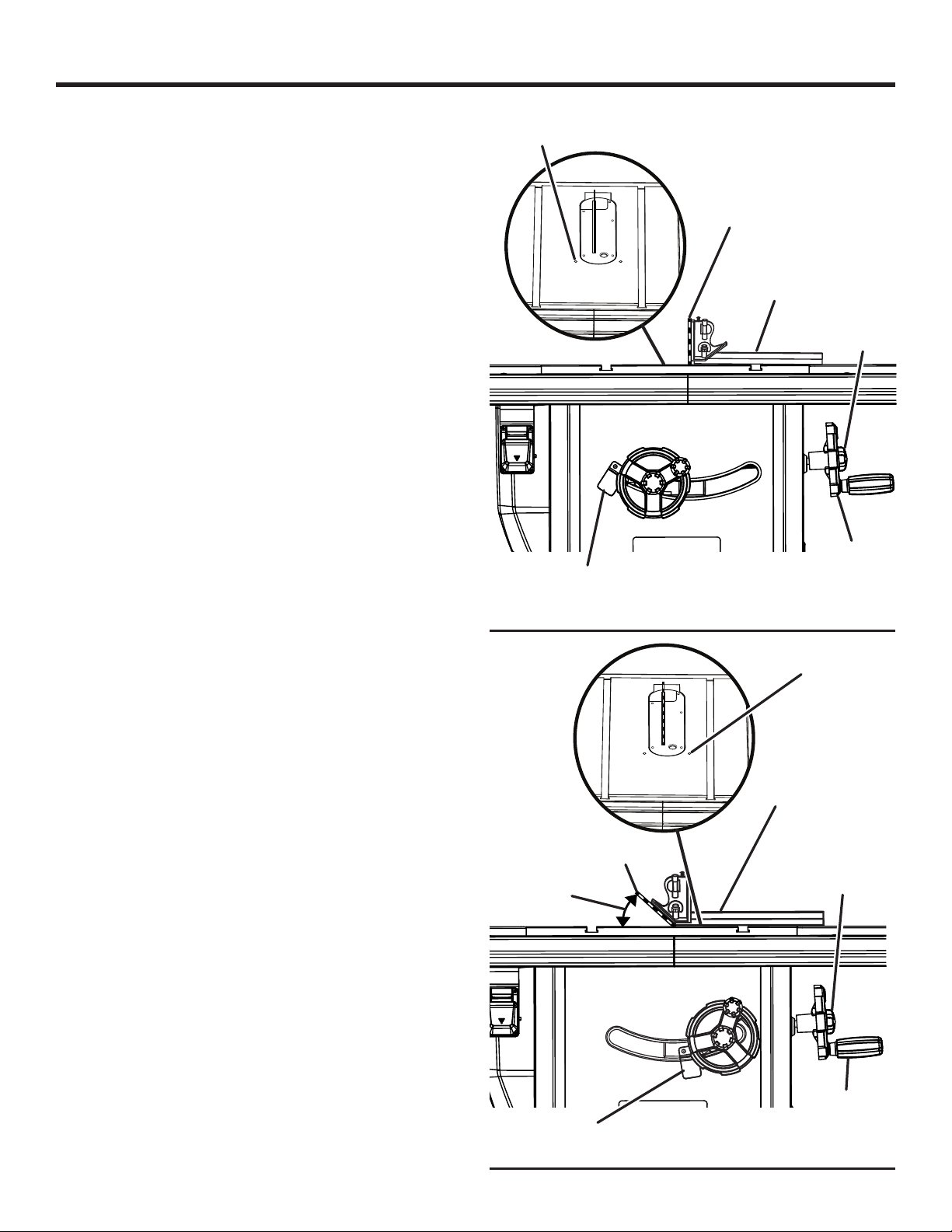
ADJUSTMENTS
TO SET THE BLADE AT 0° AND 45°
See Figures 74 - 75.
The angle settings of your saw have been set at the factory
and, unless damaged in shipping, should not require setting
during assembly. After extensive use, it may need to be
checked.
Unplug the saw.
Raise the blade by unlocking the height adjusting
handwheel and turning it clockwise.
Remove the blade guard.
If the blade is not perfectly vertical (0°):
Loosen the 0º adjustment screw and the bevel lock knob.
Place a combination square beside the blade on the left.
Lock the angle by tightening the bevel lock knob and
retighten the adjustment bolt.
NOTE: Make sure that the square contacts the flat part
of the saw blade, not the blade teeth.
Turn the bevel handle until the bevel indicator points to
zero. If the bevel handle is turned as far as possible and
doesn’t indicate zero properly, you may need to adjust
the bevel indicator.
If the blade is not an exact 45°:
Loosen the adjustment screw and the bevel lock knob.
NOTE: Make sure that the square contacts the flat part
of the saw blade, not the blade teeth.
Place a combination square beside the blade on the left.
Lock the angle by tightening the bevel lock knob and
retighten the adjustment bolt.
Turn the bevel handle until the bottom of the blade has
moved completely to the left side of the slot. Lock the
angle by tightening the bevel lock knob.
If the blade is not an exact 45°, loosen the adjustment
bolt and the bevel lock knob.
Adjust the bevel indicator to 45°.
Make a test cut.
The adjustment screws must be below the saw table surface
so the workpiece doesn’t catch on uneven edges. If unable
to make this adjustment, take the product to an authorized
service center.
0° ADJUSTMENT
SCREW
BEVEL
INDICATOR
45°
BLADE
BLADE
COMBINATION
SQUARE
BEVEL LOCK
KNOB
BEVEL
HANDLE
Fig. 74
45° ADJUSTMENT
SCREW
COMBINATION
SQUARE
BEVEL LOCK
KNOB
BEVEL
BEVEL
INDICATOR
47 - English
Find Quality Products Online at: [email protected]
www.GlobalTestSupply.com
HANDLE
Fig. 75
Page 48
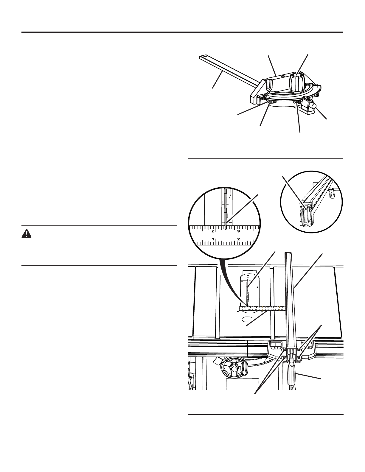
ADJUSTMENTS
TO ADJUST THE MITER GAUGE
See Figure 76.
You can set the miter gauge at 0° and plus or minus 45°
with the miter gauge stop pin and adjustable stop screws.
NOTE: The miter gauge provides close accuracy in angled
cuts. For very close tolerances, test cuts are recommended.
Loosen knob and pull out on stop pin to rotate miter
gauge base past stop screws.
Loosen the lock nut of the 0° stop screw at the stop pin
with a 8 mm wrench.
Place a 90° square against the miter gauge rod and the
miter gauge base.
If the rod is not square, loosen the knob, adjust the rod,
and tighten the knob.
Adjust the 0° stop screw until it rests against the stop pin.
Adjust the plus and minus 45° stop screws using a 45°
triangle and the steps above.
TO CHECK AND ADJUST THE ALIGNMENT OF
THE RIP FENCE
See Figure 77.
The rip fence must be parallel to the saw blade and the miter
gauge grooves.
MITER
GAUGE ROD
45° ADJUSTABLE
STOP SCREW
MITER
GAUGE BASE
LOCK
NUT
CLAMP
SCREW
BLADE
TOOTH
KNOB
STOP
PIN
0° ADJUSTABLE
STOP SCREW
Fig. 76
WARNING:
A misaligned rip fence can cause kickbacks and
jams. To reduce the risk of injury, always maintain
proper rip fence alignment.
Unplug the saw.
Remove the blade guard, riving knife, and anti-kickback
pawls. Raise the blade by unlocking the height adjusting
handwheel and turning it clockwise.
Verify the blade is parallel to the miter gauge groove as
described in the Adjusting the Blade Parallel to the Miter
Gauge Groove (Removing Heel) section in Operations.
Move the rip fence near the saw blade (about three inches
away) and lock the rip fence in place with the locking
handle.
Mark beside one of the blade teeth at the front of the
blade. Using a ruler, measure the distance from the inside
face of the blade tooth to the to the inside face of the rip
fence.
NOTE: For greater accuracy, place the marked blade
tooth on top of the ruler.
Turn the blade so the marked tooth is at the back.
Move the ruler to the rear and again measure the distance
from the inside face of the blade tooth to the inside face
of the rip fence. If the distances are the same, the blade
and the rip fence are parallel.
RULER
SCREWS
BLADE
RIP FENCE
SCREWS
LOCKING
HANDLE
Fig. 77
48 - English
Find Quality Products Online at: [email protected]
www.GlobalTestSupply.com
Page 49
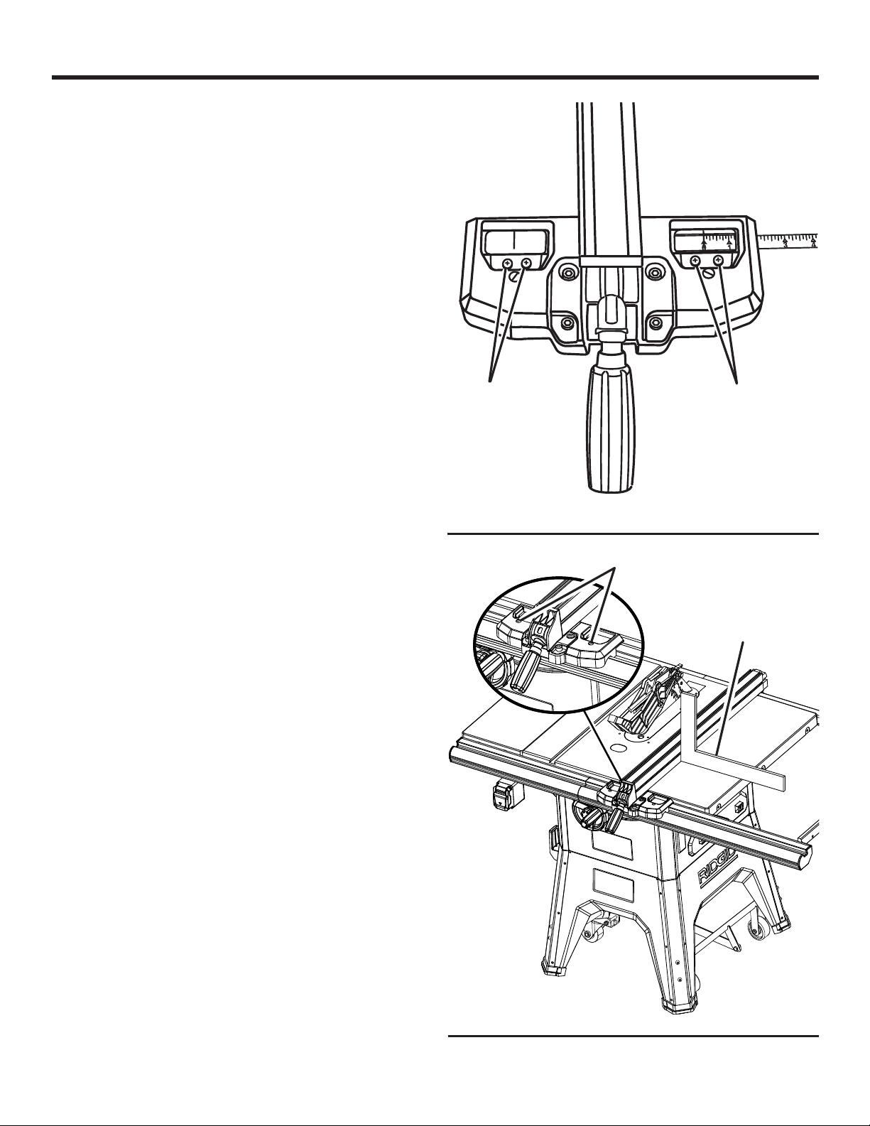
ADJUSTMENTS
If the distances are different:
Loosen the four screws on the rip fence.
Adjust the rip fence.
Alternately retighten the screws. Recheck alignment.
Repeat steps as needed until rip fence is correctly aligned.
Replace blade guard, riving knife, and anti-kickback pawls.
Make two or three test cuts on scrap wood. If the cuts
are not true, repeat the process.
NOTE: The rip fence must be secure when the locking handle
is engaged. The clamp screw on the rear of the rip fence is
tightened by turning clockwise to increase tightness of the
rear of the rip fence. Adjust if needed.
TO ADJUST THE RIP FENCE INDICATOR
See Figures 78 - 79.
The rip fence has two indicators: one for use when the rip
fence is on the right side of the saw blade and one for use
when the rip fence is on the left side of the saw blade.
NOTE: The blade guard assembly must be removed to
perform this adjustment. Reinstall the blade guard assembly
when the adjustment is complete.
Unplug the saw.
Place the rip fence on the saw table so that it lightly
touches the right side of the saw blade. Lock the rip fence
in place.
Loosen pan head screw and adjust the right indicator so
that the red line is located over the “zero” line on the right
rip scale on the front rail. Retighten screw.
Reposition the rip fence on the saw table so that it lightly
touches the left side of the saw blade. Lock the rip fence
in place.
Loosen pan head screw and adjust the left indicator so
that the red line is located over the “zero” line on the left
rip scale on the front rail. Retighten screw.
If the indicator cannot be set to zero after performing the
adjustments described above, the position of the rail must
be adjusted. See Installing the Rails Onto the Saw Table
earlier in this manual.
The rip fence should sit at 90º to the top of the saw table.
If an adjustment is needed:
Set a framing square on the saw table next to the rip
fence.
Use a flat head screwdriver to loosen or tighten one of
the angle adjustment screws.
Adjust the screws until the angle measures 90º on each
side of the rip fence.
PAN HEAD
SCREW
PAN HEAD
SCREW
Fig. 78
ANGLE ADJUSTMENT
SCREW
FRAMING
SQUARE
Fig. 79
49 - English
Find Quality Products Online at: [email protected]
www.GlobalTestSupply.com
Page 50
MAINTENANCE
WARNING:
When servicing, use only identical replacement
parts. Use of any other parts could create a
hazard or cause product damage.
WARNING:
Always wear eye protection with side shields
marked to comply with ANSI Z87.1 during
product operation. If operation is dusty, also wear
a dust mask.
WARNING:
Before performing any maintenance, make sure
the tool is unplugged from the power supply and
the switch is in the OFF ( O ) position. Failure to
heed this warning could result in serious personal
injury.
GENERAL MAINTENANCE
Avoid using solvents when cleaning plastic parts. Most
plastics are susceptible to damage from various types of
commercial solvents and may be damaged by their use. Use
clean cloths to remove dirt, dust, oil, grease, etc.
WARNING:
Do not at any time let brake fluids, gasoline,
petroleum-based products, penetrating oils, etc.,
come in contact with plastic parts. Chemicals can
damage, weaken or destroy plastic which could
result in serious personal injury.
Periodically check all clamps, nuts, bolts, screws, and
belts for tightness and condition. Make sure the throat
plate is in good condition and in position.
Check the blade guard assembly.
To maintain the table surfaces, fence, and rails,
periodically clean and buff to provide smooth functioning.
To prevent work from slipping during cutting operation,
Do not wax the working face of the miter gauge.
Protect the blade by cleaning out saw dust from
underneath the table and in the blade teeth. Use a resin
solvent on the blade teeth.
Clean plastic parts only with a soft damp cloth. Do
not use any aerosol or petroleum solvents.
LUBRICATION
This saw’s motor bearings have been packed at the factory
with proper lubrication.
Clean screw threads and nuts with a solvent
recommended for gum and pitch removal.
Lubricate screw threads, nuts, and bearing points
(including those on the blade guard assembly and miter
gauge).
50 - English
Find Quality Products Online at: [email protected]
www.GlobalTestSupply.com
Page 51
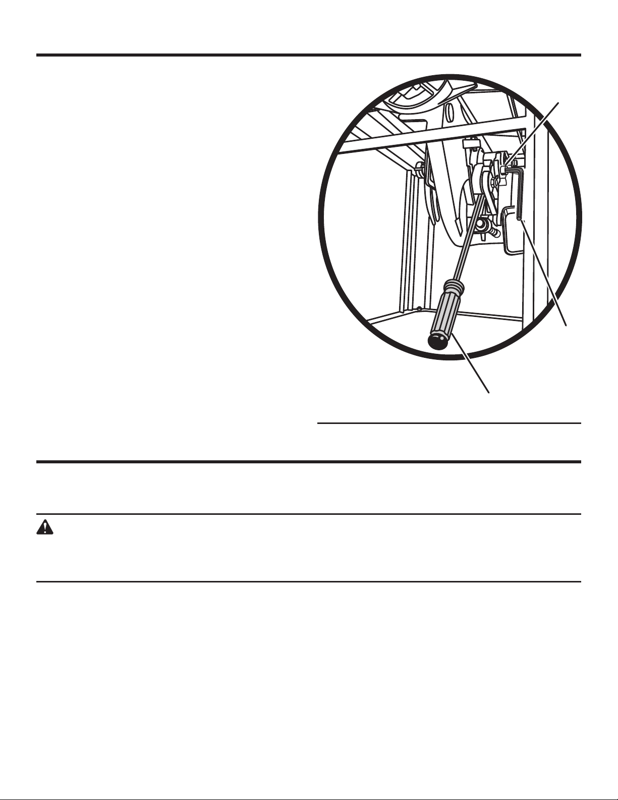
MAINTENANCE
CLEANING THE DUST CHUTE
Clean the dust chute periodically to remove sawdust.
Using a 4 mm hex key, remove the screws that secure
the back panel.
Inspect the dust chute and attached dust collection
devices to clear away sawdust or other debris.
Replace the back panel.
TO REMOVE AND CHANGE BELT
See Figure 80.
Lower the blade by unlocking the height adjusting
handwheel and turning it counterclockwise.
Using a 4 mm hex key, remove the screws that secure
the back panel.
With a 6 mm hex key, loosen the bolt above and to the
right of the belt.
Pull the belt off the pulleys.
Insert a long flat blade screwdriver as shown.
Holding the screwdriver in place, pull the new belt over
both pulleys, making sure it is properly placed.
Remove the screwdriver.
Tighten the bolt.
BOLT
HEX
KEY
SCREWDRIVER
Fig. 80
ACCESSORIES
Look for these accessories where you purchased this product or call 1-866-539-1710:
Dado Throat Plate ........................................................................................................................................080035003093
WARNING:
Current attachments and accessories available for use with this tool are listed above. Do not use any attachments
or accessories not recommended by the manufacturer of this tool. The use of attachments or accessories not
recommended can result in serious personal injury.
51 - English
Find Quality Products Online at: [email protected]
www.GlobalTestSupply.com
Page 52
TROUBLESHOOTING
Problem Cause Solution
Excess vibration. Blade is out of balance.
Blade is damaged.
Saw is not mounted securely.
Work surface is uneven.
Blade is warped.
Rip fence does not move smoothly. Rip fence not mounted correctly.
Rails are dirty or sticky.
Clamp screw is out of adjustment.
Rip fence does not lock at rear. Clamp screw is out of adjustment. Adjust clamp screw.
Cutting binds or burns work. Blade is dull.
Blade is heeling.
Work is fed too fast.
Rip fence is misaligned.
Riving Knife is out of alignment.
Wood is warped.
Wood edges away from rip fence when
ripping.
Rip fence is misaligned. Check and adjust the rip fence.
Replace blade.
Replace blade.
Tighten all hardware.
Reposition on flat surface.
Replace blade.
Remount the rip fence.
Clean and wax rails.
Adjust clamp screw.
Replace or sharpen blade.
See Adjusting the Blade Parallel to
the Miter Gauge Groove (Removing
Heel) in the Operation section.
Slow the feed rate.
Align the rip fence.
See “To check and align the riving knife
and saw blade” in the Assembly section.
Replace the wood. Always cut with
convex side to table surface.
52 - English
Find Quality Products Online at: [email protected]
www.GlobalTestSupply.com
Page 53
TROUBLESHOOTING
Problem Cause Solution
Saw does not make accurate 90˚ or
45˚ cuts.
Height and/or bevel adjusting handwheel is hard to turn.
Saw does not start. Motor cord or wall cord is not plugged in.
Blade makes poor cuts. Blade is dull or dirty.
Blade does not lower when turning
height adjusting handwheel.
Motor labors in rip cut. Blade not proper for rip cut. Change blade; rip blade typically has
Positive stops inside cabinet need
adjusting (Bevel Cuts).
Miter gauge is misaligned (Miter Cuts).
Gears or screw post inside cabinet are
clogged with saw dust.
Circuit fuse is blown.
Circuit breaker is tripped.
Cord or switch is damaged.
Blade is wrong type for cut being made.
Blade is mounted backwards.
Locking lever is not at full left position.
Blade cover is dirty.
Adjust positive stops.
Adjust the miter gauge.
Clean the gears or screw post.
Plug in motor cord or wall cord.
Replace circuit fuse.
Reset circuit breaker.
Have the cord or switch replaced by
qualified service center.
Clean, sharpen, or replace blade.
Replace with correct type.
Remount blade.
Move locking lever to left.
See cleaning instructions in the
Maintenance section.
fewer teeth.
53 - English
Find Quality Products Online at: [email protected]
www.GlobalTestSupply.com
Page 54

WARRANTY
RIDGID® HAND HELD AND STATIONARY POWER TOOL
3 YEAR LIMITED SERVICE WARRANTY
Proof of purchase must be presented when requesting
warranty service.
Limited to RIDGID
purchased 2/1/04 and after. This product is manufactured
by One World Technologies, Inc. The trademark is licensed
from RIDGID, Inc. All warranty communications should be
directed to One World Technologies, Inc., attn: RIDGID Hand
Held and Stationary Power Tool Technical Service at (toll
free) 1-866-539-1710.
®
hand held and stationary power tools
90-DAY SATISFACTION GUARANTEE POLICY
During the first 90 days after the date of purchase, if you
are dissatisfied with the performance of this RIDGID® Hand
Held or Stationary Power Tool for any reason you may return
the tool to the dealer from which it was purchased for a full
refund or exchange. To receive a replacement tool you must
present proof of purchase and return all original equipment
packaged with the original product. The replacement tool
will be covered by the limited warranty for the balance of
the 3 YEAR service warranty period.
WHAT IS COVERED UNDER THE 3 YEAR
LIMITED SERVICE WARRANTY
This warranty on RIDGID® Hand Held and Stationary Power
Tools covers all defects in workmanship or materials and
normal wear items such as brushes, chucks, motors,
switches, cords, gears and even cordless batteries in this
RIDGID® tool for three years following the purchase date of
the tool. Warranties for other RIDGID® products may vary.
WHAT IS NOT COVERED
This warranty applies only to the original purchaser at retail
and may not be transferred. This warranty only covers
defects arising under normal usage and does not cover
any malfunction, failure or defect resulting from misuse,
abuse, neglect, alteration, modification or repair by other
than an authorized service center for RIDGID® branded hand
held and stationary power tools. Consumable accessories
provided with the tool such as, but not limited to, blades,
bits and sand paper are not covered.
RIDGID, INC. AND ONE WORLD TECHNOLOGIES, INC.
MAKE NO WARRANTIES, REPRESENTATIONS OR
PROMISES AS TO THE QUALITY OR PERFORMANCE OF
ITS POWER TOOLS OTHER THAN THOSE SPECIFICALLY
STATED IN THIS WARRANTY.
ADDITIONAL LIMITATIONS
To the extent permitted by applicable law, all implied
warranties, including warranties of MERCHANTABILITY or
FITNESS FOR A PARTICULAR PURPOSE, are disclaimed. Any
implied warranties, including warranties of merchantability or
fitness for a particular purpose, that cannot be disclaimed
under state law are limited to three years from the date
of purchase. One World Technologies, Inc. and RIDGID,
Inc. are not responsible for direct, indirect, incidental or
consequential damages. Some states do not allow limitations
on how long an implied warranty lasts and/or do not allow
the exclusion or limitation of incidental or consequential
damages, so the above limitations may not apply to you.
This warranty gives you specific legal rights, and you may
also have other rights which vary from state to state.
54 - English
Find Quality Products Online at: [email protected]
www.GlobalTestSupply.com
 Loading...