

Page 1

micro CA-100
Inspection Camera
•
WARNING!
Read this Operator’s Man ual
carefully before using this
tool. Failure to understand
and follow the contents of this
manual may result in electrical shock, fire and/or serious
person al injury.
micro CA-100 Operator’s Manual
Find Quality Products Online at: [email protected]
www.GlobalTestSupply.com
Page 2

ii
micro CA-100 Inspection Camera
Table of Contents
Safety Symbols ....................................................................................................2
General Safety Information
Work Area Safety...............................................................................................2
Electrical Safety.................................................................................................2
Personal Safety .................................................................................................2
Equipment Use and Care ..................................................................................2
Service...............................................................................................................3
Specific Safety Information
micro CA-100 Inspection Camera Safety .........................................................3
Description, Specifications and Standard Equipment
Description.........................................................................................................4
Specifications.....................................................................................................4
Standard Equipment..........................................................................................4
Controls .............................................................................................................4
FCC Statement .....................................................................................................5
Electromagnetic Compatibility (EMC)................................................................5
Tool Assembly
Changing/Installing Batteries.............................................................................5
Installing Imager Head Cable or Extension Cables ...........................................5
Installing An Accessory......................................................................................6
Pre-Operation Inspection ....................................................................................6
Tool and Work Area Set-Up .................................................................................7
Operating Instructions ........................................................................................8
Viewing ..............................................................................................................8
Maintenance
Cleaning.............................................................................................................9
Reset Function...................................................................................................9
Accessories..........................................................................................................9
Storage..................................................................................................................9
Service and Repair...............................................................................................9
Disposal ................................................................................................................9
Battery Disposal...................................................................................................9
Troubleshooting .................................................................................................10
Lifetime Warranty.................................................................................Back Cover
*Original Instructions - English
Find Quality Products Online at: [email protected]
www.GlobalTestSupply.com
Page 3
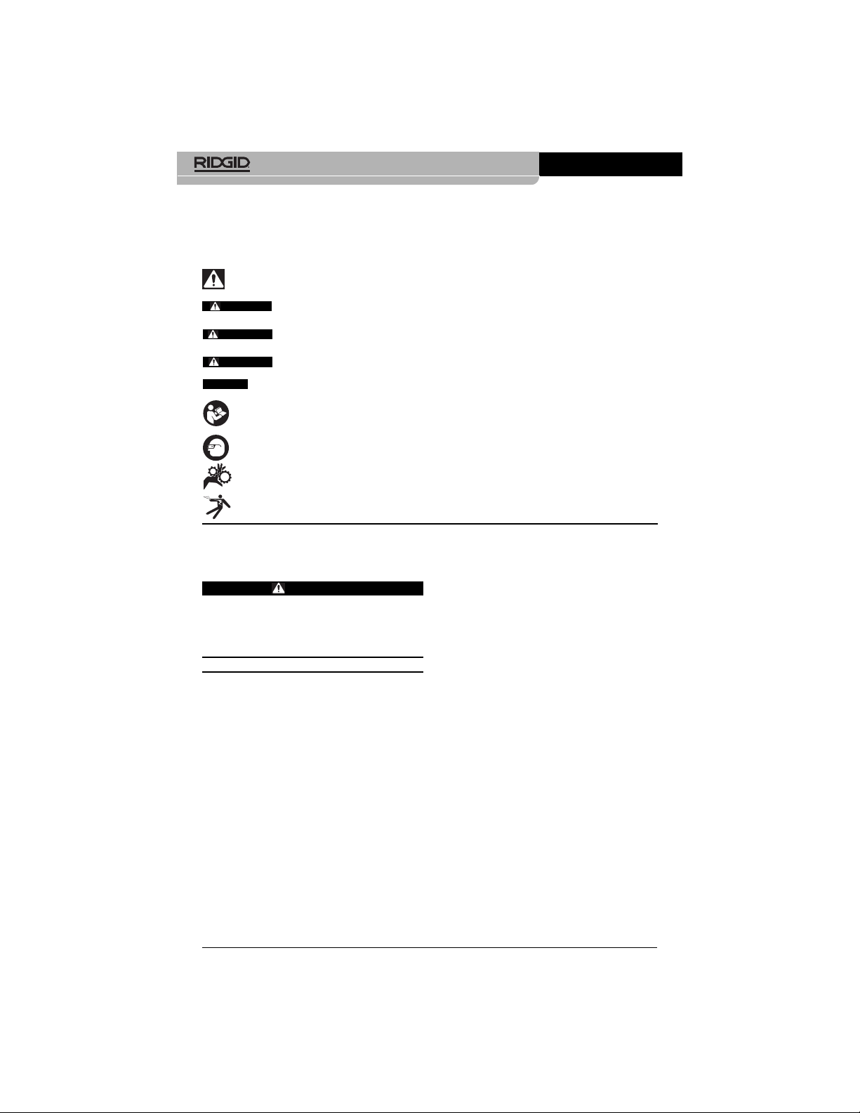
Safety Symbols
In this operator’s manual and on the product, safety symbols and signal words are used to
communicate important safety information. This section is provided to improve understanding of these signal words and symbols.
This is the safety alert symbol. It is used to alert you to potential personal injury hazards. Obey
all safety messages that follow this symbol to avoid possible injury or death.
DANGER indicates a hazardous situation which, if not avoided, will result in death or
serious injury.
WARNING indicates a hazardous situation which, if not avoided, could result in
death or serious injury.
CAUTION indicates a hazardous situation which, if not avoided, could result in minor
or moderate injury.
NOTICE indicates information that relates to the protection of property.
This symbol means read the operator’s manual carefully before using the equipment. The operator’s manual contains important information on the safe and proper operation of the equipment.
This symbol means always wear safety glasses with side shields or goggles when handling
or using this equipment to reduce the risk of eye injury.
This symbol indicates the risk of hands, fingers or other body parts being caught or wrapped
in gears or other moving parts.
This symbol indicates the risk of electrical shock.
• Do not expose equipment to rain or
wet conditions. Water entering equipment will increase the risk of electrical
shock.
Personal Safety
• Stay alert, watch what you are doing
and use common sense when operating equipment. Do not use equipment
while you are tired or under the influence of drugs, alcohol or medication. A
moment of inattention while operating
equipment may result in serious personal
injury.
• Do not overreach. Keep proper footing
and balance at all times. This enables
better control of the power tool in unexpected situations.
• Use personal protective equipment.
Always wear eye protection. Protective
equipment such as dust mask, non-skid
safety shoes, hard hat or hearing protection used for appropriate conditions will
reduce personal injuries.
Equipment Use and Care
• Do not force equipment. Use the correct
equipment for your application. The cor-
rect equipment will do the job better and
safer at the rate for which it is designed.
2
micro CA-100 Inspection Camera
General Safety
Information
WARNING
Read all safety warnings and instructions. Failure to follow the warnings and
instructions may result in electric shock,
fire and/or serious injury.
SAVE THESE INSTRUCTIONS!
Work Area Safety
• Keep your work area clean and well lit.
Cluttered or dark areas invite accidents.
• Do not operate equipment in explosive
atmospheres, such as in the presence
of flammable liquids, gases or dust. E-
quipment can create sparks which may
ignite the dust or fumes.
• Keep children and by-standers away
while operating equipment. Distractions
can cause you to lose control.
Electrical Safety
• Avoid body contact with earthed or
grounded surfaces such as pipes, radiators, ranges and refrigerators. There is
an increased risk of electrical shock if your
body is earthed or grounded.
NOTICE
DANGER
WARNING
CAUTION
Find Quality Products Online at: [email protected]
www.GlobalTestSupply.com
Page 4

Read these precautions carefully before
using the micro CA-100 Inspection Camera to reduce the risk of electrical shock
or other serious injury.
SAVE THESE INSTRUCTIONS!
A manual holder is supplied in the carrying
case of the micro CA-100 Inspection Camera
to keep this manual with the tool for use by
the operator.
micro CA-100 Inspection
Camera Safety
• The micro CA-100 imager head and ca-
ble are waterproof to 10'.The hand-held
display unit is not. Do not expose the
display unit to water or rain. This increases
the risk of electrical shock.
• Do not place the micro CA-100 Inspec-
tion Camera anywhere that may contain a live electrical charge. This in-
creases the risk of electrical shock.
• Do not place the micro CA-100 Inspec-
tion Camera anywhere that may contain moving parts. This increases the
risk of entanglement injuries.
• Do not use this device for personal in-
spection or medical use in any way.
This is not a medical device. This could
cause personal injury.
• Always use appropriate personal pro-
tective equipment while handling and
using the micro CA-100 Inspection
Camera. Drains and other areas may con-
tain chemicals, bacteria and other substances that may be toxic, infectious,
cause burns or other issues. Appropriate
personal protective equipment always
includes safety glasses and gloves, and
may include equipment such as latex or
rubber gloves, face shields, goggles, protective clothing, respirators and steel-toed
footwear.
• Practice good hygiene. Use hot, soapy
water to wash hands and other exposed
body parts exposed to drain contents after
handling or using the micro CA-100 Inspection Camera to inspect drains and
other areas that may contain chemicals
or bacteria. Do not eat or smoke while operating or handling the micro CA-100
Inspection Camera. This will help prevent
contamination with toxic or infectious material.
• Do not use equipment if the switch
does not turn it ON and OFF. Any tool
that cannot be controlled with the switch is
dangerous and must be repaired.
• Disconnect the batteries from the equip-
ment before making any adjustments,
changing accessories, or storing. Such
preventive safety measures reduce the risk
of injury.
• Store idle equipment out of the reach of
children and do not allow persons unfamiliar with the equipment or these instructions to operate the equipment.
Equipment can be dangerous in the hands
of untrained users.
• Maintain equipment. Check for misalign-
ment or binding of moving parts, missing
parts, breakage of parts and any other
condition that may affect the equipment’s
operation. If damaged, have the equipment repaired before use. Many accidents
are caused by poorly maintained equipment.
• Use the equipment and accessories in
accordance with these instructions,
taking into account the working conditions and the work to be performed.
Use of the equipment for operations different from those intended could result in a
hazardous situation.
• Use only accessories that are recom-
mended by the manufacturer for your
equipment. Accessories that may be suit-
able for one piece of equipment may become hazardous when used with other
equipment.
• Keep handles dry and clean; free from
oil and grease. Allows for better control of
the equipment.
Service
• Have your equipment serviced by a
qualified repair person using only identical replacement parts. This will ensure
that the safety of the tool is maintained.
Specific Safety
Information
WARNING
This section contains important safety information that is specific to the inspection camera.
3
micro CA-100 Inspection Camera
Find Quality Products Online at: [email protected]
www.GlobalTestSupply.com
Page 5

Power Source...............4 x “AA”, Alkaline or
Rechargeable
Attachments .................Hook, Magnet,
Mirror
Weight ..........................5.5 lbs (2.5 kg)
Standard Equipment
The micro CA-100 Inspection Camera comes
with the following items:
• micro CA-100
• 17mm Imager
• 3' RCA Cable
• Hook, Magnet, Mirror Attachments
• 4 x “AA” Batteries
Figure 1 – micro CA-100
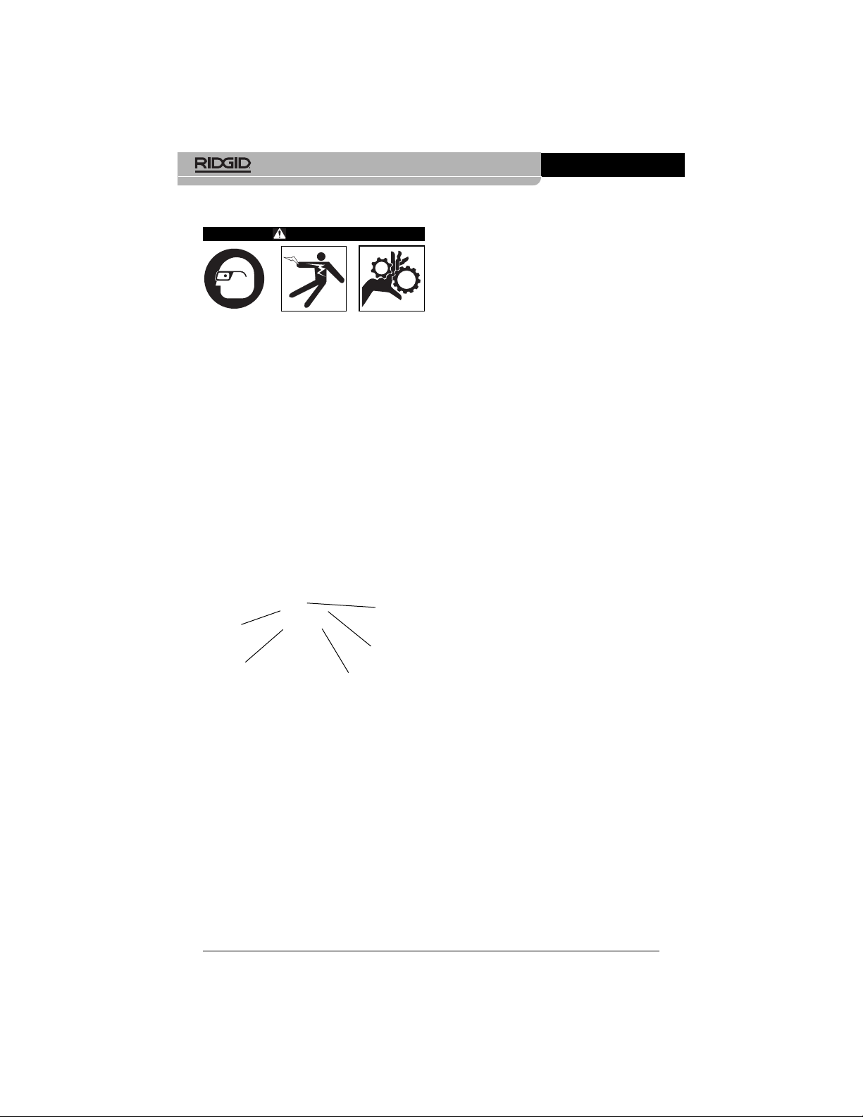
Controls
Figure 2 – Controls
• Do not operate the micro CA-100 Inspection Camera if operator or device is
standing in water. Operating an electrical
device while in water increases the risk
of electrical shock.
The EC Declaration of conformity (890-011-
320.10) will accompany this manual as a separate booklet when required.
If you have any question concerning this
RIDGID
®
product:
Description,
Specifications and
Standard Equipment
Description
The micro CA-100 Inspection Camera displays live color video from an imaging sensor
and light source that’s connected to a 3' flexible cable. It can be used to look into tight
spots and beam back real-time video to a
color LCD. It comes with a 3/4" (17 mm) camera head for general use.
Specifications
Display.........................3.5" Color LCD
(320 x 240
Resolution)
Lighting........................4 Adjustable LEDs
Cable Reach................3' (Expandable to
30' with Optional
Extensions)
Waterproof to 10'
(IP67)
Camera Head..............3/4" (17mm)
Video Output ...............RCA (3' Cable
Included)
TV-Out.........................PAL/NTSC
Operating Temp...........0° C ~ 50° C
Storage Temp ..............-20° C ~ 60° C
Storage Humidity.........15% ~ 85% RH
Depth of Field (DOF)....10mm ~ • (infinity)
4
micro CA-100 Inspection Camera
Rotate
Image
Power
LED
Brightness Decrease
Battery
Indicator
LED Brightness
Increase
Find Quality Products Online at: [email protected]
www.GlobalTestSupply.com
Page 6

Remove the batteries prior to long term storage to avoid battery leakage.
1. Squeeze the battery clips
(See Figure
3)
and remove battery compartment from
the micro CA-100 Inspection Camera
(See Figure 4)
. If needed, remove batter-
ies.
Figure 3 – Battery Compartment Cover
2. Install 4 new AA alkaline batteries (LR6),
observing the correct polarity as indicated on the battery compartment. Only
replace in sets to help prevent battery
leakage.
3. Squeeze the clips and firmly insert into inspection camera. The holder will only go
in one way. Do not force. Confirm securely attached.
Figure 4 – Battery Compartment
Installing the Imager Head
Cable or Extension Cables
To use the micro CA-100 Inspection Camera,
the imager head cable must be connected
to the handheld display unit. To connect the
cable to the handheld display unit, make sure
the key and slot
(Figure 5)
are properly
aligned. Once they are aligned, finger tighten
the knurled knob to hold the connection in
place.
FCC Statement
This equipment has been tested and found to
comply with the limits for a Class B digital
device, pursuant to part 15 of the FCC Rules.
These limits are designed to provide reasonable protection against harmful interference in
a residential installation.
This equipment generates, uses, and can radiate radio frequency energy and, if not installed and used in accordance with the instructions, may cause harmful interference
to radio communications.
However, there is no guarantee that interference will not occur in a particular installation.
If this equipment does cause harmful interference to radio or television reception, which
can be determined by turning the equipment
OFF and ON, the user is encouraged to try to
correct the interference by one or more of
the following measures:
• Reorient or relocate the receiving antenna.
• Increase the separation between the equipment and receiver.
• Consult the dealer or an experienced
radio/TV technician for help.
Electromagnetic
Compatibility (EMC)
The term electromagnetic compatibility is
taken to mean the capability of the product to
function smoothly in an environment where
electromagnetic radiation and electrostatic
discharges are present and without causing
electromagnet interference to other equipment.
The RIDGID micro CA-100 Inspection Camera conforms to all applicable EMC
standards. However, the possibility of it causing interference in other devices cannot be
precluded.
Tool Assembly
WARNING
To reduce the risk of serious injury during use, follow these procedures for
proper assembly.
Changing/Installing Batteries
The micro CA-100 is supplied without batter-
ies installed. If the battery indicator displays
red , the batteries need to be replaced.
5
micro CA-100 Inspection Camera
NOTICE
Find Quality Products Online at: [email protected]
www.GlobalTestSupply.com
Page 7
1. Make sure the unit is OFF.
2. Remove the battery holder and inspect it
and batteries for signs of damage. Replace batteries if necessary. Do not use
inspection camera if batteries are damaged.
3. Clean any oil, grease or dirt from the equipment. This aids inspection and helps
prevent the tool from slipping from your
grip.
4. Inspect micro CA-100 Inspection Camera
for any broken, warn, missing, misaligned
or binding parts or any condition which
may prevent safe and normal operation.
5. Inspect the camera head lens for condensation. To avoid damaging the unit, do not
use the camera if condensation forms
inside the lens. Let the water evaporate
before using.
6. Inspect the full length of the cable for
cracks or damage. A damaged cable
could allow water to enter the unit and increase the risk of electrical shock.
7. Check to make sure the connections between the handheld unit, extension cables and imager cable are tight. All connections must be properly assembled
for the cable to be water resistant. Confirm unit is properly assembled.
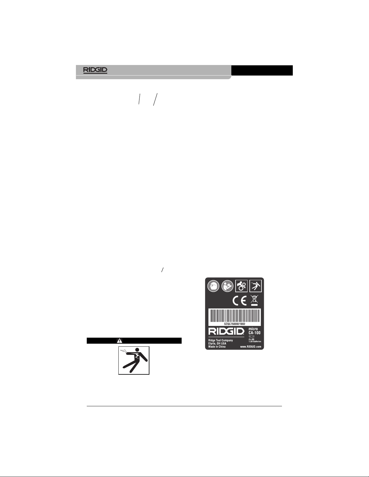
8. Check that the warning label is present,
firmly attached and readable.
Figure 7 – Warning Label
9. If any issues are found during the inspection, do not use the inspection camera until it has been properly serviced.
10. With dry hands, re-install the battery holder making sure to fully insert.
Figure 5 – Cable Connections
3' and 6' cable extensions are available to
increase the length of your cable up to 30' in
length. To install an extension, first remove the
camera head cable from the display unit by
loosening the knurled knob. Connect the extension to the handheld as described above
(Figure 5)
. Connect the keyed end of the
camera head cable to the slotted end of the
extension and finger tighten the knurled knob
to hold the connection in place.
Installing An Accessory
The three included accessories, (mirror, hook
and magnet)
(Figure 1)
all attach to the imager
head the same way.
To connect, hold the imager head as shown in
Figure 6
. Slip the semicircle end of the accessory over the flats of the imager head as
shown in
Figure 6
. Then rotate the accessory
a 1/4 turn so the long arm of the accessory is
extending out as shown
(Figure 6)
.
Figure 6
Pre-Operation
Inspection
WARNING
Before each use, inspect your inspection camera and correct any problems
to reduce the risk of serious injury from
electric shock and other causes and
prevent tool damage.
Slot
Key
Accessory
6
micro CA-100 Inspection Camera
Find Quality Products Online at: [email protected]
www.GlobalTestSupply.com
Page 8
• Determine if there is any electrical
power supplied to the area to be inspected. If so, the power to the area
must be turned off to reduce the risk of
electric shock. Use appropriate lock
out procedures to prevent the power
from being turned back on during the inspection.
• Determine if any liquids will be encountered during the inspection. The cable
and imager head are waterproof to a
depth of 10'. Greater depths may cause
leakage into the cable and imager and
cause electric shock or damage the
equipment. The handheld display unit is
not water resistant and should not be
exposed to wet conditions.
• Determine if any chemicals are present, especially in the case of drains. It is
important to understand the specific
safety measures required to work around
any chemicals present. Contact the
chemical manufacturer for required information. Chemicals may damage or degrade the inspection camera.
• Determine the temperature of the area
and items in the area. The working
temperature of the inspection camera is
between 32 and 122 degrees F (0°C 50°C). Use in areas outside of this
range or contact with hotter or colder
items could cause camera damage.
• Determine if any moving parts are present in the area to be inspected. If so,
these parts must be deactivated to prevent movement during inspection to
reduce the risk of entanglement. Use
appropriate lock out procedures to prevent the parts from moving during the
inspection.
If the micro CA-100 Inspection Camera is not
the correct piece of equipment for the job,
other inspection equipment is available from
RIDGID. For a complete listing of RIDGID
products, see the RIDGID catalog, online at
3. Make sure the micro CA-100 Inspection
Camera has been properly inspected
before each use.
4. Install the correct accessories for the application.
11. Press and Hold the Power Button for 3
seconds. A splash screen will appear.
Once the camera is ready an image will
appear. Consult the
Troubleshooting
sec-
tion of this manual if problems arise.
12. Press and Hold the Power Button for 3
seconds to turn the unit OFF.
Tool and Work Area
Set-Up
WARNING
Set up the micro CA-100 Inspection Camera and work area according to these
procedures to reduce the risk of injury
from electrical shock, entanglement and
other causes and prevent tool and system damage.
1. Check work area for:
• Adequate lighting
• Flammable liquids, vapors or dust that
may ignite. If present, do not work in
area until sources have been identified
and corrected. The micro CA-100 Inspection Camera is not explosion proof
and can cause sparks.
• Clear, level, stable, dry place for opera-
tor. Do not use the inspection camera
while standing in water.
2. Examine the area or space that you will
be inspecting and determine if the micro
CA-100 Inspection Camera is the correct
piece of equipment for the job.
• Determine the access points to the
space. The minimum opening the camera head can fit through is approximately
3
/4" in diameter for the 17 mm camera
head.
• Determine the distance to the area to
be inspected. Extensions can be added to the camera to reach up to 30'.
• Determine if there are any obstacles
that would require very tight turns in
the cable. The inspection camera cable can go down to a 2" (50mm) radius
without damage.
7
micro CA-100 Inspection Camera
Find Quality Products Online at: [email protected]
www.GlobalTestSupply.com
Page 9
Operating Instructions
WARNING
Always wear eye protection to protect
your eyes against dirt and other foreign
objects.
Follow operating instructions to reduce
the risk of injury from electrical shock,
entanglement and other causes.
1. Make sure that the inspection camera
and work area have been properly set up
and that the work area is free of bystanders and other distractions.
Figure 8 – Controls
2. Power On: Press and Hold the power
button for 3 seconds.
The power status light will come ON. If
the power status light is GREEN, the
micro CA-100 Inspection Camera batteries are good. If the power status light is
RED, the batteries need to be changed. If
the LED does not turn ON, the batteries
need to be changed or the unit needs
service. The splash screen will appear.
3. Pre-Form The Cable: If needed for the
area to be inspected, pre-form the cable.
Do not try to form bends with a radius of
less than 2", this can damage the cable.
micro CA-100 Inspection Camera
8
4. LED Brightness Adjustment: Turn the
LEDs ON. The imager head is equipped
with four white LEDs to aid inspection.
Use the + and – buttons to turn ON and
adjust the brightness of the LEDs.
5. Inspection: Insert the imager head and
cable into the space to be inspected. Do
not use the imager head or cable for
anything other than an inspection device. Do not use the imager head and
cable to clear a path. Do not force the imager head and cable through tight bends
or spaces. These uses can damage the
unit and the area to be inspected.
6. Image Rotation: If needed, the image
seen on the screen can be rotated in 90
degree increments counter clockwise by
pressing the rotate image button.
7. Power Off: When the inspection is com-
plete, carefully withdraw the imager and
cable from the inspection area. Press
and Hold the power button for 1 second
to turn the unit OFF. The unit will automatically turn OFF 30 minutes after the
last button press or if the batteries drop
too low.
Viewing
The micro CA-100 Inspection Camera can be
connected to a television or other monitor for
remote viewing or recording through the included RCA cable. Open the rubber cover on
the side of the grip and insert the RCA cable
into the TV-OUT jack.
Insert the other end into the Video In jack on
the television or monitor. The television or
monitor may need to be set to the proper
input to allow viewing.
Figure 9 – TV-OUT Jack/Reset Button
Rotate
Image
Power
LED
Brightness Decrease
Battery
Indicator
LED Brightness
Increase
Find Quality Products Online at: [email protected]
www.GlobalTestSupply.com
Page 10
Maintenance
WARNING
Remove batteries before cleaning.
Cleaning
• Always clean the imager head and cable
after use with mild soap or mild detergent.
• Gently clean the LCD with a clean dry
cloth. Avoid rubbing too hard on the LCD.
• Use only alcohol swabs to clean the cable
connections.
• Wipe the hand held display unit down with
a clean, dry cloth.
Reset Function
If the unit stops functioning and does not operate, press the Reset Button.
(See Figure 9.)
The unit may recover to normal operation
when restarted.
Accessories
WARNING
To reduce the risk of serious injury, only
use accessories specifically designed
and recommended for use with the
RIDGID micro CA-100 Inspection Camera
such as those listed below. Other Accessories suitable for use with other
tools may be hazardous when used with
the micro CA-100 Inspection Camera.
Storage
The RIDGID micro CA-100 Inspection Camera must be stored in a dry secure area between -20°C (-4°F) and 60°C (140°F).
Store the tool in a locked area out of the
reach of children and people unfamiliar with
the micro CA-100 Inspection Camera.
Remove the batteries before any long period
of storage or shipping to avoid battery leakage.
micro CA-100 Inspection Camera
9
Service and Repair
WARNING
Improper service or repair can make the
RIDGID micro CA-100 Inspection Camera
unsafe to operate.
Service and repair of the micro CA-100 Inspection Camera must be performed by a
RIDGID Independent Authorized Service
Center.
For information on your nearest RIDGID Independent Service Center or any service or
repair questions:
Disposal
Parts of the RIDGID micro CA-100 Inspection
Camera contain valuable materials and can
be recycled. There are companies that specialize in recycling that may be found locally.
Dispose of the components in compliance
with all applicable regulations. Contact your
local waste management authority for more information.
For EC Countries: Do not dispose
of electrical equipment with household waste!
According to the European Guideline 2002/96/EC for Waste Elec-
trical and Electronic Equipment and
its implementation into national legislation,
electrical equipment that is no longer usable
must be collected separately and disposed of
in an environmentally correct manner.
Battery Disposal
For EC countries: Defective or used batteries
must be recycled according to the guideline
2006/66/EEC.
micro CA-100 Inspection Camera
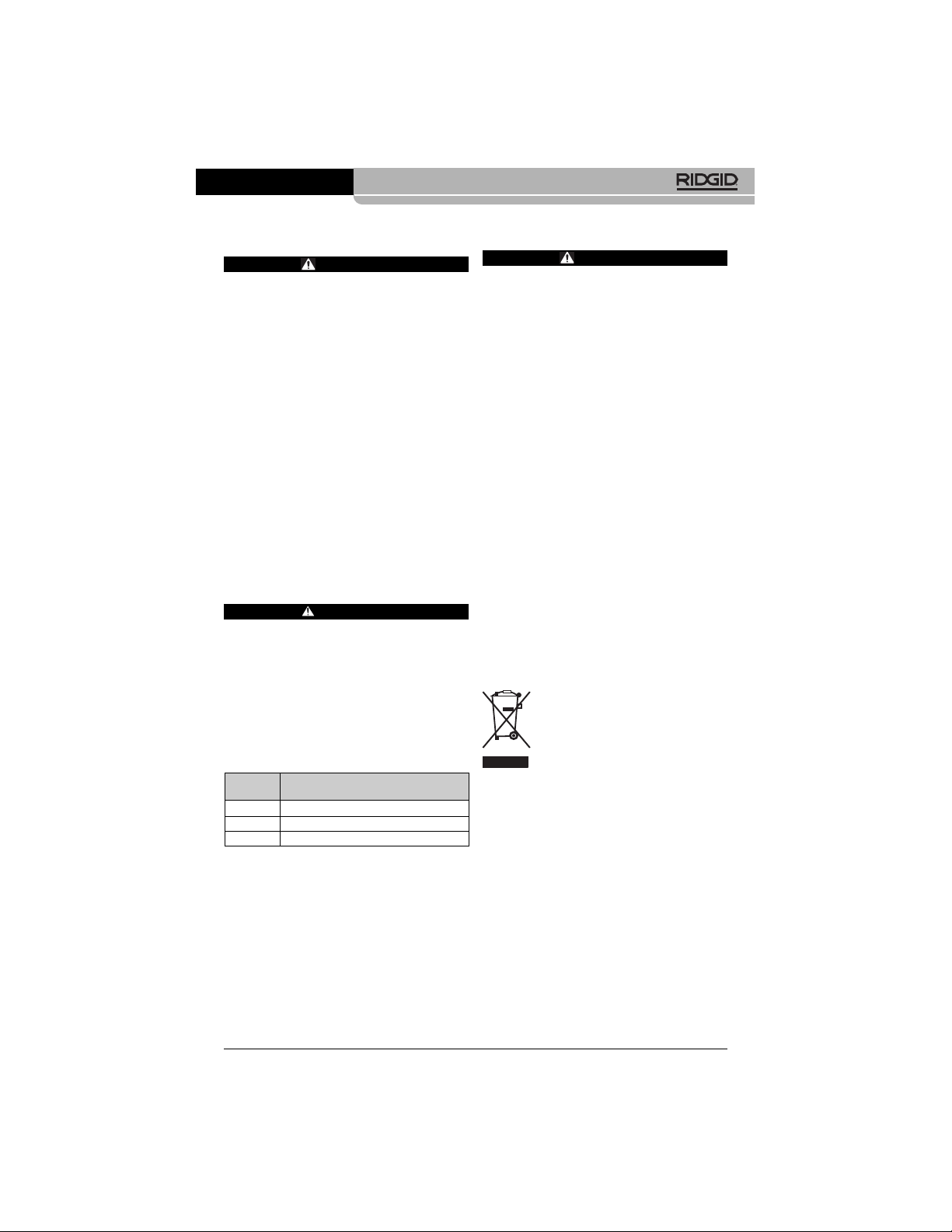
Accessories*
Catalog
No. Description
31128 3' Cable Extension
31133 6' Cable Extension
37103 Imager Head and Cable - 17 mm
(*List subject to change.)
Find Quality Products Online at: [email protected]
www.GlobalTestSupply.com
Page 11
micro CA-100 Inspection Camera
10
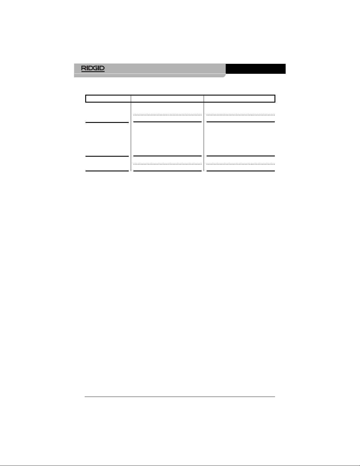
SYMPTOM POSSIBLE REASON SOLUTION
Display turns ON, but
does not show image.
LEDs on imager head
are dim at max brightness, display switches
between black and
white, color display
turns itself OFF after a
brief period.
Unit will not turn ON.
Troubleshooting
Loose cable connections.
Imager is broken.
Battery low on power.
Dead batteries.
Unit need to be reset.
Check cable connections, clean if required. Re-attach.
Replace the Imager.
Replace batteries.
Replace batteries.
Reset unit.
See “Maintenance” Section.
Find Quality Products Online at: [email protected]
www.GlobalTestSupply.com
 Loading...