

Page 1
• Français – 13
• Castellano – pág. 27
Power Pipe Cutter
OPERATOR’S
MANUAL
258
258XL
W ARNING!
Read this Operator’s Manual
carefully before using this
tool. Failure to understand
and follow the contents of
this manual may result in
electrical shock, fire and/or
serious personal injury.
Page 2

Ridge Tool Companyii
258/258XL Power Pipe Cutters
Table of Contents
General Safety Information
Work Area Safety........................................................................................................................................................2
Electrical Safety..........................................................................................................................................................2
Personal Safety ..........................................................................................................................................................2
Tool Use and Care......................................................................................................................................................3
Service........................................................................................................................................................................3
Specific Safety Information
Switch Safety..............................................................................................................................................................3
Cutter Safety ..............................................................................................................................................................3
Description, Specifications and Accessories
Description..................................................................................................................................................................4
Specifications..............................................................................................................................................................4
Standard Equipment ..................................................................................................................................................4
Accessories ................................................................................................................................................................4
Assembly Instructions..................................................................................................................................................5
Pipe Cutter Inspection..................................................................................................................................................6
Pipe Cutter and Work Area Set-Up
Using Pipe Supports ..................................................................................................................................................7
Operating Instructions for Cutting Pipe
Cutting Thin Wall Pipe ................................................................................................................................................8
Special Procedures
Adjusting Pivot Arm for Correct Pipe Size (258 Only) ................................................................................................9
Changing the Cutter Wheel ........................................................................................................................................9
Transporting..............................................................................................................................................................10
Transporting Using the Transport Cart ....................................................................................................................10
Maintenance Instructions ..........................................................................................................................................11
Machine Storage..........................................................................................................................................................11
Service and Repair......................................................................................................................................................11
Trouble Shooting ........................................................................................................................................................12
Lifetime Warranty ........................................................................................................................................Back Cover
Page 3

258/258XL
Power Pipe Cutter
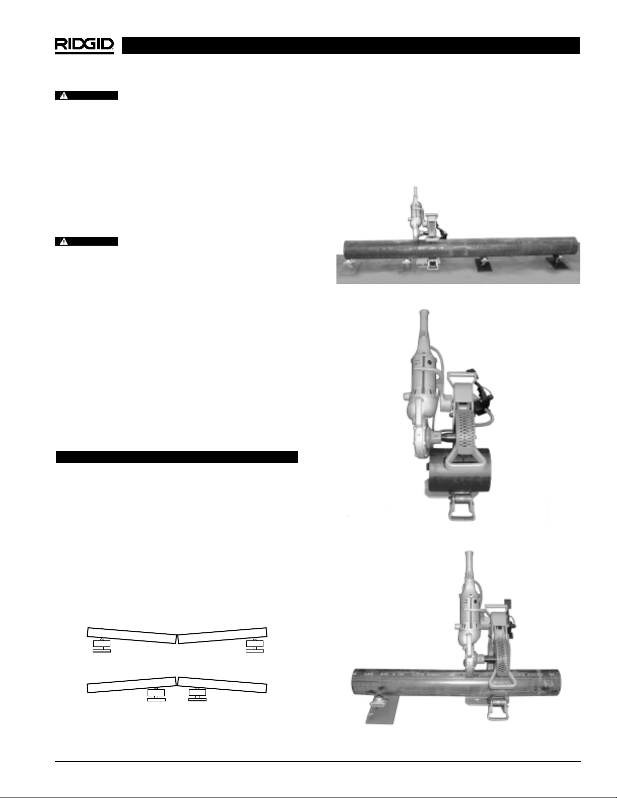
No. 258XL Power Pipe Cutter
with 700 Power Drive
No. 258 Power Pipe Cutter
with 700 Power Drive
Page 4
Ridge Tool Company2
258/258XL Power Pipe Cutters
General Safety Information
WARNING! Read and understand all instructions.
Failure to follow all instructions listed
below may result in electric shock, fire,
and/or serious personal injury.
SAVE THESE INSTRUCTIONS!
Work Area Safety
• Keep your work area clean and well lit. Cluttered
benches and dark areas invite accidents.
• Do not operate power tools in explosive atmo-
spheres, such as in the presence of flammable
liquids, gases, or dust. Power tools create sparks
which may ignite the dust or fumes.
• Keep by-standers, children, and visitors away
while operating a power tool. Distractions can cause
you to lose control.
Electrical Safety
• Grounded tools must be plugged into an outlet,
properly installed and grounded in accordance
with all codes and ordinances. Never remove the
grounding prong or modify the plug in any way. Do
not use any adapter plugs. Check with a qualified
electrician if you are in doubt as to whether the outlet is properly grounded. If the tools should electrically
malfunction or break down, grounding provides a low
resistance path to carry electricity away from the user.
• Avoid body contact with grounded surfaces such
as pipes, radiators, ranges and refrigerators.
There is an increased risk of electrical shock if your
body is grounded.
• Don’t expose power tools to rain or wet condi-
tions. Water entering a power tool will increase the risk
of electrical shock.
• Do not abuse cord. Never use the cord to carry
the tools or pull the plug from an outlet. Keep cord
away from heat, oil, sharp edges or moving parts.
Replace damaged cords immediately. Damaged
cords increase the risk of electrical shock.
• When operating a power tool outside, use an out-
door extension cord marked “W-A” or “W”. These
cords are rated for outdoor use and reduce the risk of
electrical shock.
• Use only three-wire extension cords which have
three-prong grounding plugs and three-pole receptacles which accept the machine plug. Use of other
extension cords will not ground the tool and increase
the risk of electrical shock.
• Use proper extension cords. (See chart.) Insufficient conductor size will cause excessive voltage
drop, loss of power and overheating.
• Keep all electric connections dry and off the
ground. Do not touch plugs or tool with wet
hands. Reduces the risk of electrical shock.
Personal Safety
• Stay alert, watch what you are doing and use
common sense when operating a power tool. Do
not use tool while tired or under the influence of
drugs, alcohol, or medications. A moment of inat-
tention while operating power tools may result in
serious personal injury.
• Dress properly. Do not wear loose clothing or jew-
elry. Contain long hair. Keep your hair, clothing,
and gloves away from moving parts. Loose clothes,
jewelry, or long hair can be caught in moving parts.
• Avoid accidental starting. Be sure switch is OFF
before plugging in. Carrying tools with your finger on
the switch or plugging tools in that have the switch ON
invites accidents.
• Remove adjusting keys or switches before turning
the tool ON. A wrench or a key that is left attached to
a rotating part of the tool may result in personal injury.
• Do not over-reach. Keep proper footing and bal-
ance at all times. Proper footing and balance enables
better control of the tool in unexpected situations.
• Use safety equipment. Always wear eye protection.
Dust mask, non-skid safety shoes, hard hat, or hearing protection must be used for appropriate conditions.
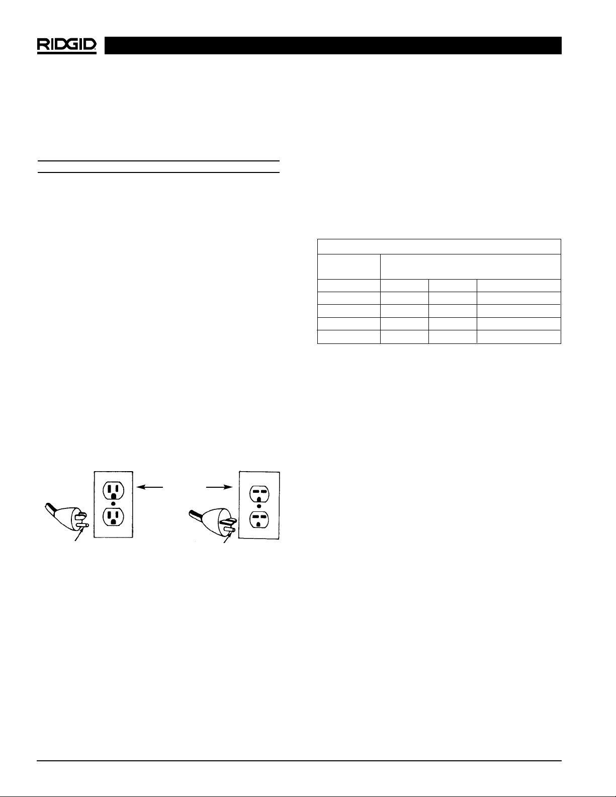
Grounding prong
Cover of
grounded
outlet box
Grounding prong
Minimum Wire Gauge for Extension Cord
Nameplate
Amps Total Length (in feet)
0-25 26-50 51-100
0-6 18 AWG 16 AWG 16 AWG
6-10 18 AWG 16 AWG 14 AWG
10-12 16 AWG 16 AWG 14 AWG
12-16 14 AWG 12 AWG
NOT RECOMMENDED
Page 5

Ridge Tool Company 3
258/258XL Power Pipe Cutters
Tool Use and Care
• Do not force tool. Use the correct tool for your
application. The correct tool will do the job better
and safer at the rate for which it is designed.
• Do not use tool if switch does not turn it ON or
OFF. Any tool that cannot be controlled with the switch
is dangerous and must be repaired.
• Disconnect the plug from the power source before
making any adjustments, changing accessories, or
storing the tool. Such preventive safety measures
reduce the risk of starting the tool accidentally.
• Store idle tools out of the reach of children and
other untrained persons. Tools are dangerous in
the hands of untrained users.
• Maintain tools with care. Keep cutting tools sharp
and clean. Properly maintained tools with sharp cutting
edges are less likely to bind and are easier to control.
• Check for misalignment or binding of moving
parts, breakage of parts, and any other condition
that may affect the tools operation. If damaged,
have the tool serviced before using. Many acci-
dents are caused by poorly maintained tools.
• Inspect tool and extension cords periodically and
replace if damaged. Damaged cords increase the risk
of electrical shock.
• Keep handles dry and clean; free from oil and
grease. Allows for better control of the tool.
Service
• Tool service must be performed only by qualified
repair personnel. Service or maintenance performed
by unqualified repair personnel could result in injury.
• When servicing a tool, use only identical replacement parts. Follow instructions in the Maintenance
Section of this manual. Use of unauthorized parts or
failure to follow maintenance instructions may create a
risk of electrical shock or injury.
SAVE THESE INSTRUCTIONS!
Specific Safety Information
WARNING
Read this operator’s manual carefully before using
the 258/258XL Pipe Cutters. Failure to understand
and follow the contents of this manual may result in
electrical shock, fire and/or serious personal injury.
Call the Ridge Tool Company, Technical Service
Department at (800) 519-3456 if you have any questions.
Switch Safety
The momentary contact switch incorporated in the power
drive is for your safety. It lets you shut off the motor by
removing your finger. If clothing should become caught in
the pipe or cutter, it will continue to wind up, pulling you
into the machine. Because the power drive has high torque,
the clothing itself can bind around your arm or other body
parts with enough force to crush or break bones.
Cutter Safety
• Cutter is made to cut 21/2″ through 8″ or 8″ through
12″. Follow instructions in operator’s manual on
proper use. Other uses may increase risk of injury.
• Keep fingers and hands away from cutter blade.
Reduces risk of being cut.
• Keep guards in place. Removal of guards increases
the risk of injury.
• Set-up cutter and 258 pipe supports on a flat, level
surface. Be sure the cutter is stable and will not tip
over. Do not use on a bench or any elevated surface. Improper set-up increases the risk of injury.
• Do not use if momentary contact switch for the
700 Power Drive is broken. The purpose of the switch
is to prevent injuries.
• Secure the 700 Power Drive properly to the cutter.
Carefully follow set-up instructions. Place foot
pump behind cutter and near the power drive.
Position the power cord clear of the blade. Improper
set-up increases the risk of injury.
• Keep all personnel clear of rotating pipe. Use
barricades if necessary. Prevents entanglement
in the pipe.
• Do not use with dull, bent or damaged cutter
wheels. Less likely to bind and lose control.
• Do not reach across cutter or rotating pipe. May
become entangled in the tool causing serious injury.
• Keep hands and feet clear of the pipe in the event
it falls after being cut. High pressure exerted by the
cutter may cause the cut section to fly with considerable force. May result in serious injury.
WARNING
Page 6
Accessories
• 700 Power Drive (110 or 220 Volt)
• 258PS Ball Transfer Head Pipe Supports (2)
• Transport Cart for 258 and 258XL
• Cutter Wheel for Thin Wall Pipe
(Schedule 10 – 20 capacity)
• Pipe Roller for Beveling
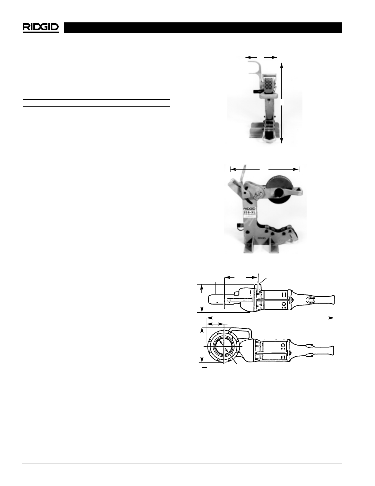
Figure 1A
C
A
Figure 1
• Cutter is designed for use with the RIDGID 700
Power Drive. Use of other power drives may increase
the risk of injury.
• Wear leather gloves when handling pipe. Burrs
can penetrate cloth gloves.
SAVE THESE INSTRUCTIONS!
Description, Specifications and
Standard Equipment
Description
The RIDGID 258 and 258XL Power Pipe Cutters are
designed to squarely cut 21/2″ to 8″ or 8″ – 12″ steel
pipe. The cutting action is powered by the RIDGID 700
Power Drive in conjunction with a large diameter cutter
wheel. The cutter wheel is advanced to the pipe via a
pivot arm. The pivot arm advances the cutter wheel by
utilizing a 10-ton hydraulic cylinder and foot pump.
The RIDGID 700 Portable Power Drive is an electromotor-driven heavy-duty power drive which provides
power for threading pipe, conduit and rod (bolt stock). In
this case, the 700 Portable Power Drive is used as the
power source to rotate the cutting blade.
Specifications
Description ....................258 258XL
Pipe Cutting Capacity.....21/2″ – 8″ 8″ – 12″
Height (A)......................22″ 27″
Width (B) .......................11″ 13″
Depth (C).......................19″ 24″
Weight
(without 700 PD).........95 lbs. 130 lbs.
(with 700 PD).............126 lbs. 161 lbs.
Standard Equipment
• 258 or 258XL Cutter Frame
• Two Speed Foot Pump with Hose and Coupling
• 774 Square Drive Adapter for 700 PD
• 258PS Ball Transfer Head Pipe Supports (2)
• E258 General Purpose Cutting Wheel
(Schedule 40 – 80 Capacity)
258/258XL Power Pipe Cutters
Ridge Tool Company4
Figure 2 – No. 700 Power Drive Dimensions
1
/2″ NPT79/16″
281/4″
39/16″
7
13
/16″
35/8″ I.D.
2
3
/8″
61/16″
▼
▲
B
Page 7
Assembly Instructions
WARNING
To prevent serious injury, proper assembly of the
Pipe Cutter is required. The following procedures
should be followed:
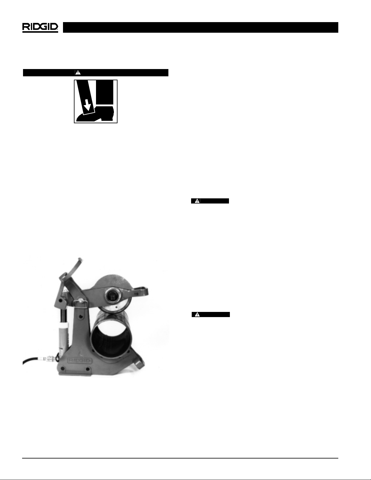
1. Connecting the hydraulic foot pump to the cutter.
a. Insert the male end of the quick-disconnect cou-
pling into the female end located on the hydraulic
cylinder (Figure 3).
b. The foot pump relief valve must be depressed to
release any line pressure and allow insertion of
the quick connector.
Failure to secure the power drive with the
reaction arm will result in the rotation of the power drive.
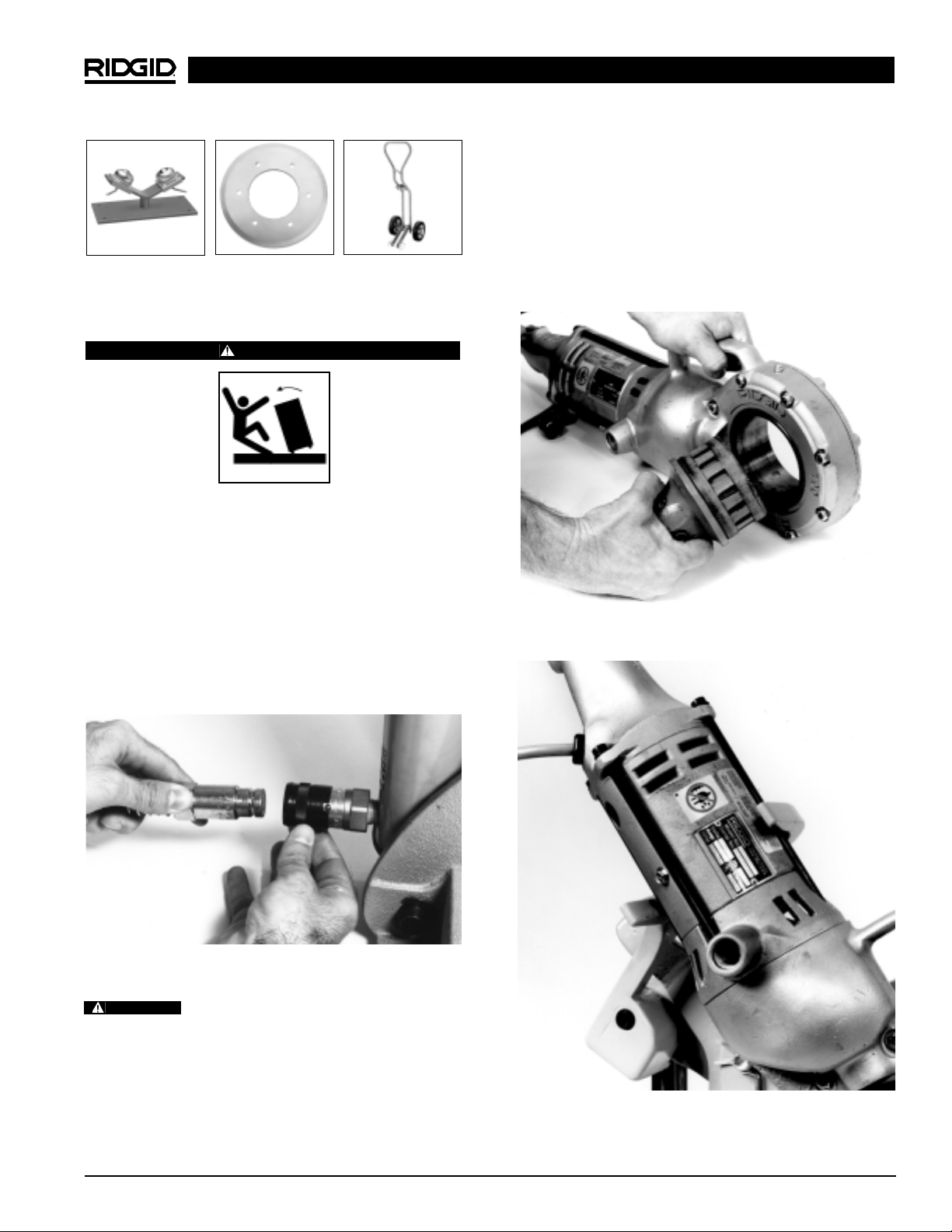
2. Connecting the 700 Power Drive to the cutter.
a. Push 774 Square Drive Adapter, spline end first,
squarely into power drive face gear until spring
loaded adapter pawls catch securely (Figure 4).
Ridge Tool Company 5
258/258XL Power Pipe Cutters
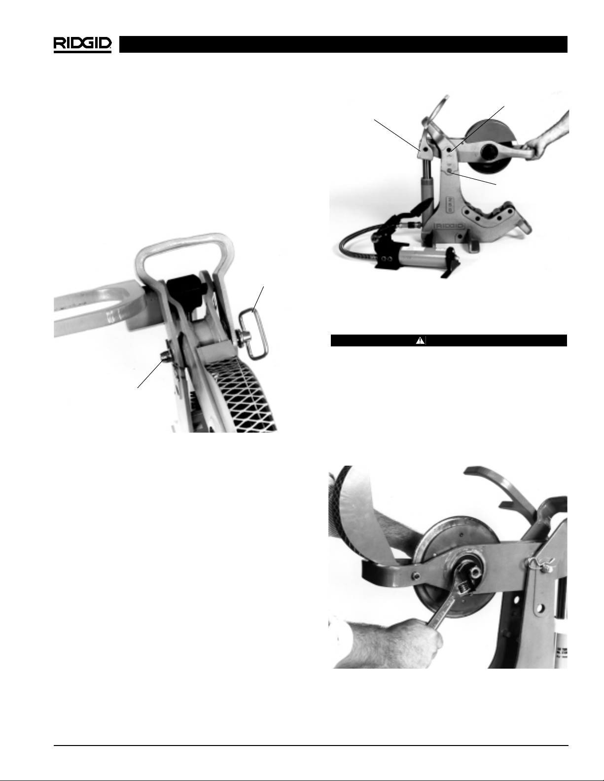
b. Place power drive with adapter on the cutter.
Power drive and adapter connect to the square
drive on the cutter. Be sure power drive rests
inside the reaction arm at the rear of the cutter
(Figure 5).
c. Hand tighten the two set screws on the 774
square drive adapter to the square drive with
5
/16″ allen wrench. (Provided with adapter.)
Ball Transfer Head
Cutter Wheel Transport Cart
Figure 3 – Connecting Hydraulic Foot Pump to Cutter
Figure 4 – Installing 774 Drive Adapter
WARNING
Figure 5 – Position Power Drive Inside Reaction Arm
Page 8

Pipe Cutter Inspection
WARNING
To prevent serious injury, inspect your Pipe Cutters
and Power Drive. The following inspection procedures should be performed on a daily basis:
1. Make sure Power Drive is unplugged.
2. Inspect the cutter wheel to insure it is not dull, bent or
damaged. Refer to the Special Procedures if it needs
to be replaced.
3. Check that the cutter frame rollers are free to rotate
under the pipe. Clean debris, pipe scale and dirt
from rollers.
4. Insure pipe support ball transfer heads are free to
move and are clean of dirt, pipe scale and debris.
5. Insure the three screws and lock washers are tight in
the cutter wheel assembly.
6. Check fluid levels in the hydraulic foot pump. Insure
fluid level is to the FULL MARK when the ram is
fully retracted when checking level of fluid.
7. Check that cutter wheel guard is in place.
8. Inspect the power cord and plug for damage. If the
plug has been modified, is missing the grounding
pin or if the cord is damaged, do not use the Power
Drive until the cord has been replaced.
9. Inspect the Pipe Cutter and Power Drive for any broken, missing, misaligned or binding parts as well as
any other conditions which may affect the safe and
normal operation of the tool. If any of these conditions
are present, do not use the tool until any problem has
been repaired.
10. Use tools and accessories that are specifically
designed for your Power Cutter and meet the needs
of your application. The correct tools and accessories allow you to do the job successfully and safely.
Accessories suitable for use with other equipment
may be hazardous when used with this equipment.
11. Clean any oil, grease or dirt from all handles and
controls. This reduces the risk of injury due to a tool
or control slipping from your grip.
Pipe Cutter and Work Area
Set-Up
WARNING
To prevent serious injury, proper set-up of the Pipe
Cutter and work area is required. The following procedures should be followed to set-up the machine.
1. Locate a work area that has the following:
• Adequate lighting.
• No flammable liquids, vapors or dust that may ignite.
• Grounded electrical outlet.
• Clear path to the electrical outlet that does not
contain any sources of heat or oil, sharp edges or
moving parts that may damage electrical cord.
• Dry place for machine and operator. Do not use
the machine while standing in water.
• Level ground. Do not use on bench or elevated
surface.
2. Set-up guards or barricades to create a minimum of
three (3) feet of clearance around the Pipe Cutter and
workpiece. This “safety zone” prevents others from
accidentally contacting the tool or workpiece and
either causing the equipment to tip or becoming
entangled in the rotating pipe.
3. Adjust the pivot arm holding the pipe cutter wheel to
the correct pipe size (258 only). The pivot arm must be
positioned for either 21/2″ through 4″ pipe or 6″through
8″. See “Special Procedures” for instructions.
4. Position the pump behind the cutter and near the
power drive so that the operator can safely control the
tool and workpiece. It should allow the operator to do
the following:
• Stand facing the pipe.
• Have convenient access to the power drive switch
and foot pump.
Tool is designed for one person operation.
5. Plug the Power Drive into the electrical outlet making
sure to position the power cord along the clear path
selected earlier. If the power cord does not reach the
outlet, use an extension cord in good condition. Be
sure power cord is clear of the cutter wheel.
258/258XL Power Pipe Cutters
Ridge Tool Company6
Page 9
Ridge Tool Company 7
258/258XL Power Pipe Cutters
2. Actual placement of the pipe supports will vary
depending on the position of the cutter and the
length of pipe. Figure 7 illustrates typical set-ups of
the pipe supports.
NOTE! The cutting of long sections of pipe may require
four (4) pipe supports.
Figure 7A – Longer Lengths
Figure 7B – Very Short Lengths
Figure 7C – Short to Medium Length
To avoid electrical shock and electrical
fires, never use an extension cord that is damaged or
does not meet the following requirements:
• The cord has a three-prong plug similar to shown
in Electrical Safety section.
• The cord is rated as “W” or “W-A” if being used
outdoors.
• The cord has sufficient wire thickness (14 AWG
below 25′/12 AWG 25′- 50′). If the wire thickness is
too small, the cord may overheat, melting the cord’s
insulation or causing nearby objects to ignite.
To reduce risk of electrical shock, keep
all electrical connections dry and off the ground. Do
not touch plug with wet hands.
6. Check the Power Drive to insure it is operating
properly.
• Depress the switch and make sure it controls the
stopping of the Power Drive by releasing the switch.
• Depress and hold the switch. Inspect the moving
parts for misalignment, binding, odd noises or any
other unusual conditions that may affect the safe
and normal operation of the tool. If such conditions are present, have the power drive serviced.
• Depress switch in the opposite direction. Check
that the power drive rotates in an opposite direction.
Using Pipe Supports
CAUTION
Pipe supports must be used to prevent cutter
wheel damage. Failure to properly support the
pipe will result in shortened wheel life.
Two (2) ball transfer head pipe supports are
shipped with the 258 and 258XL Cutters. When cutting pipe in lengths of 18″ or longer, additional
pipe supports must be used.
1. As shown in Figure 6, the cutter and pipe supports
must be positioned so that the pipe sections have a
tendency to fall away from the cutter blade as the pipe
is cut. If the cutter wheel is pinched by the pipe, it will
damage the cutter wheel.
Figure 6 – Position Pipe Supports So That Cutter Wheel
Is Not Pinched By The Pipe
WARNING
WARNING
INCORRECT
CORRECT
Page 10
Ridge Tool Company8
258/258XL Power Pipe Cutters
Operating Instructions
WARNING
Keep fingers and hands away from cutter wheel.
Do not reach across cutter or pipe. Keep hands
and feet clear of pipe.
Cutter is designed for use with RIDGID 700 Power
Drive. Power Drive must be secured by the reaction arm.
Be sure cutter is on a flat, level surface and the
pipe is properly supported by pipe stands.
1. Be sure pipe is properly supported by pipe supports
and will not pinch and damage the cutter wheel.
2. Mark the pipe at the desired length for cutting (use
chalk or pipe marker).
3. Position pipe at marked point to the cutter wheel.
Insure pipe is resting squarely on cutter frame rollers.
Use foot pump to square pipe to the cutter wheel to
avoid mistracking (Figure 8).
IMPORTANT: Pipe must be free to rotate to perform cut.
4. Assure the correct operating position behind the
pipe. Exert foot pressure on foot pump. Continue
pumping foot pump to advance pivot arm and cutter
wheel to the pipe.
5. After wheel comes in contact with pipe, pump an
additional 2 or 3 strokes, start 700 Power Drive. The
pipe will start rotating once cutter wheel engages
the pipe.
6. Pump repeatedly (3 to 4 times), this will “seat” the cut-
ter wheel. Allow the pipe to rotate one or two revolutions without pumping.
7. Repeat pumping the foot pump three to four times
then allow pipe to simply rotate for one or two revolutions before pumping again. Continue this process
until pipe is cleanly cut through.
NOTE! Do not pump too aggressively. May distort pipe or
damage cutter wheel. Complete at least one
revolution before depressing the foot pump again.
Cutting Thin Wall Pipe
NOTE! The 258 and 258XL have a general purpose
cutter wheel as standard equipment. This wheel
is primarily designed to cut Schedule 40 pipe.
Do not use thin wheel on Schedule 40 or
greater pipe! Cutter wheel damage will result.
For thin wall pipe (Schedule 10-20) use a thin wheel
available as an accessory (see catalog for ordering information).
With the thin wheel installed use the following procedure:
• Position pipe on both pipe supports aligned with
cutter.
• Pump foot pump several times to lower cutter wheel
onto pipe (do not over pump).
• Pump twice to apply cutter wheel pressure.
• Start the 700 Power Drive.
• Pump once every 5 seconds (3-4 pipe revolutions).
Do not force cutter. May cause personal
injury or wheel damage.
• Repeat above step until cut is complete.
• Number of pumps and cutting time will vary with
pipe diameter, schedule and material.
CAUTION
WARNING
Figure 8 – Positioning Pipe in Cutter
Page 11
Special Procedures
Adjusting Pivot Arm for Correct Pipe
Size (258 Only)
1. The 258 is designed to cut pipe from 21/2″ through 8″
in diameter. The pivot arm holding the cutter wheel
must be adjusted depending upon the size of the
pipe being cut. The 258 is shipped from the factory
with the pivot arm positioned for 21/2″ through 4″
pipe cutting. To set the cutter for 6″ through 8″ diameter pipes, do the following:
a. Remove the hairpin cotter and hitch pin from
the pivot arm (Figure 9). Reposition the pivot
arm to the locating hole marked, 6″ – 8″. (HINT:
Activate the foot pump to elevate the pivot arm.)
Align the hole on the pivot arm with the hole in the
cutter frame and insert the hitch pin and hairpin
cotter. Use handle on front end of pivot arm to
reposition (Figure 10).
NOTE! The hitch pin can be inserted from either side.
However, it is easiest to insert the hitch pin
from the opposite side of the power drive.
b. Repeat this process when adjusting the cutter for
21/2″ through 4″ pipe. Use the locating hole
marked, 21/2″ – 4″.
Changing the Cutter Wheel
WARNING
Unplug power cord when replacing cutter wheel or
conducting other maintenance.
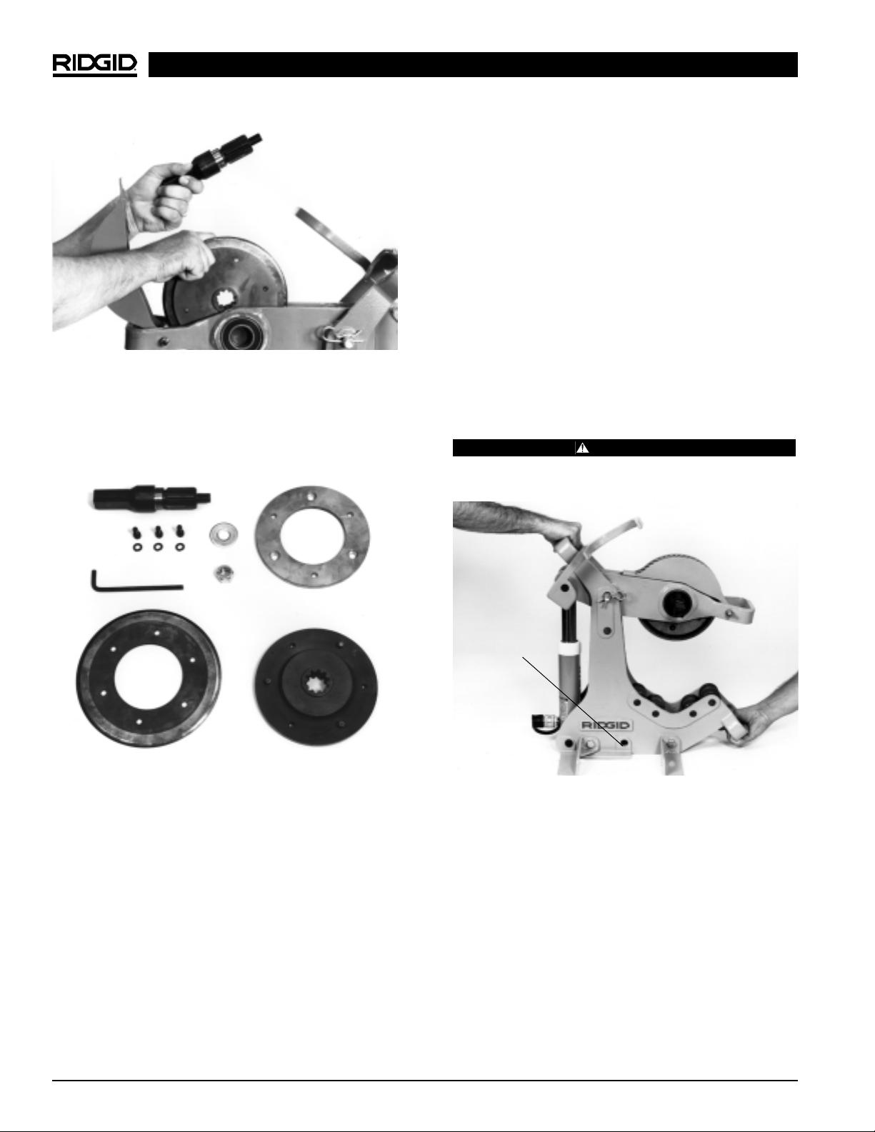
1. To replace worn cutter wheel:
a. Remove 774 square drive adapter and power
drive from the square drive.
b. Locate locking nut on opposite side of square
drive (Figure 11). With adjustable wrench or
15
/16″
wrench, loosen nut and remove. Remove washer.
258/258XL Power Pipe Cutters
Ridge Tool Company 9
Figure 11 – Remove Locking Nut
Figure 10 – Aligning Pivot Arm
6″ – 8″
2
1
/2″ – 4″
Pivot Arm
Figure 9 – Removing Hairpin Cotter and Hitch Pin
Hitch Pin
Hairpin Cotter
Page 12
Ridge Tool Company10
258/258XL Power Pipe Cutters
c. While holding onto cutter wheel assembly, pull
drive shaft out and lift cutter wheel assembly up
through top of pivot arm (Figure 12). If necessary,
lightly tap opposite end of square drive with hammer or wrench to start removal.
NOTE! For multi-piece cutter wheel remove hub on cut-
ter wheel. Locate the three (3) allen screws with
lock washers and remove with
1
/4″ allen wrench
(supplied with cutter). Remove cover plate to
expose cutter wheel. Replace worn cutter wheel
with new wheel (Figure 12). Replace cover plate
and tighten allen screws with allen wrench.
d. Return cutter wheel assembly or new cutter wheel
to the cutter. Align square drive shaft with hub
assembly and insert until shoulder butts up against
inner race of bearing. Place washer and lock-nut
on reverse side of square drive. Tighten until locknut bottoms out against washer.
NOTE! Do not over-tighten lock-nut. When nut bot-
toms out against washer, stop. Over-tightening
can reduce wheel’s ability to turn, requiring
more power from power drive, or it may cause
wheel to not track during cut.
2. Cutter wheel should easily and freely rotate in either
direction when lock-nut is properly tightened.
Transporting
1. The 258 and 258XL are designed with hand-holds
located at top rear, and bottom of frame front, for
transporting the cutter (Figure 14). Do not use pivot
arm handle to transport, as it may cause damage to
the hydraulic cylinder.
2. Remove 700 Power Drive to reduce weight when
carrying.
WARNING
Two operators should carry the cutter when being
moved to prevent personal injury.
Transporting Using The Transport Cart
A two wheeled cart is available as an accessory to allow
for easier transporting. This transport cart, (see catalog for
ordering information), is compatible with the 258 (21/2″ –
8″) as well as the 258XL (8″ – 12″). By using a “J” clamp
on the top frame handle along with a hitch pin through a
frame hole (Figure 14), the transport cart can easily be
installed.
NOTE! Transport cart does not interfere with the oper-
ation of the cutter and can remain attached.
Figure 14 – Hand-holds for Transporting
Transport Cart
Hole
Figure 12 – Remove Cutter Wheel Assembly
Figure 13 – Cutter Wheel Assembly
Page 13

Service and Repair
WARNING
The “Maintenance Instructions” will take care of most of
the service needs of this machine. Any problems not
addressed by this section should only be handled by an
authorized RIDGID service technician.
Tool should be taken to a RIDGID Independent Authorized Service Center or returned to the factory. All repairs
made by Ridge service facilities are warranted against
defects in material and workmanship.
When servicing this tool, only identical
replacement parts should be used. Failure to follow
these instructions may create a risk of serious injury.
If you have any questions regarding the service or repair
of this machine, call or write to:
Ridge Tool Company
Technical Service Department
400 Clark Street
Elyria, Ohio 44035-6001
Tel: (800) 519-3456
E-mail: TechServices@ridgid.com
For name and address of your nearest Independent
Authorized Service Center, contact the Ridge Tool Company at (800) 519-3456 or http://www.ridgid.com
Maintenance Instructions
WARNING
Make sure Power drive is unplugged from power
source before performing maintenance or making adjustment.
1. Ensure cutter frame rollers are free to rotate under the
pipe. Clean debris, pipe scale, and dirt from rollers.
2. Ensure pipe support ball transfer heads are free to
move and are clean of dirt, pipe scale, and debris.
3. Ensure the three screws and lock washers are tight in
the cutter wheel assembly. Periodically check.
4. Check fluid levels in hydraulic foot pump. Ensure
fluid level is to the full mark when the ram is fully
retracted when checking level of fluid. When filling,
make sure fluid is added to account for the hose.
Use only high grade hydraulic oil when
replacing or adding hydraulic fluid.
Machine Storage
Motor-driven equipment must be kept
indoors or well covered in rainy weather. Store the
machine in a locked area that is out of reach of children
and people unfamiliar with cutting tools. This tool can
cause serious injury in the hands of untrained users.
258/258XL Power Pipe Cutters
Ridge Tool Company 11
CAUTION
WARNING
WARNING
Page 14

258/258XL Power Pipe Cutters
Ridge Tool Company12
Hose connections are not complete
Low hydraulic fluid
Air in hydraulic system
Cutter is not firmly clamped to pipe
Pipe is not properly supported
Cutter wheel has not been preloaded 2 or 3
pumps before starting 700 power drive
Cutter wheel is not properly assembled
774 Square Drive Adapter is not completely
inserted in 700 gear head
Pipe is out-of round
Interruption of power supply
Fuse blown
Brushes do not touch armature
Overload because of continuous operation
Insufficient cooling air
Insure hoses from pump to ram are completely
secured
Insure fluid level is at full capacity
Bleed system
Insure cutter squares itself to the pipe by pumping several times before starting power drive
Short lengths of pipe must rest squarely on cutter
frame rollers. Long lengths must be supported
with stands so the cutter can locate itself to pipe
Pump 2 to 3 strokes on foot pump after cutter
wheel contacts the pipe before starting the 700
Power Drive
Insure cutter wheel is free to rotate in either direction in hub assembly (See Directions)
Square Drive Adapter must be fully inserted,
spline first into gear head
Insure that pipe is free of flat areas or has not
been crushed
Examine supply
Install fuse
Check the brushes, renew used brushes
Let power drive cool after continuous use
Clean the air-vent opening of the motor
Problem Cause Correction
Foot pump does not
advance ram
Cutter wheel does not
track
Pipe does not rotate
700 motor does not start
Abnormal heating of
motor
Troubleshooting
Troubleshooting Table
Page 15

Tronçonneuse n° 258XL avec
système d’entraînement
n° 700
Tronçonneuse n° 258
avec système d’entraînement
n° 700
Tronçonneuses à tuyaux
258 et 258XL
Page 16

Tronçonneuses à tuyaux modèles 258 et 258XL
Ridge Tool Company14
Table des matières
Consignes générales de sécurité
Sécurité du chantier..................................................................................................................................................15
Sécurité électrique....................................................................................................................................................15
Sécurité personnelle ................................................................................................................................................15
Utilisation et entretien des outils ..............................................................................................................................16
Service après-vente..................................................................................................................................................16
Consignes de sécurité spécifiques
Sécurité de l'interrupteur ..........................................................................................................................................16
Sécurité de la tronçonneuse ....................................................................................................................................17
Description, spécifications et accessoires
Description................................................................................................................................................................17
Spécifications............................................................................................................................................................17
Equipements de base ..............................................................................................................................................17
Accessoires ..............................................................................................................................................................18
Assemblage de l’appareil ..........................................................................................................................................18
Inspection de la tronçonneuse ..................................................................................................................................19
Préparation de la tronçonneuse et du chantier
Utilisation de porte-tubes..........................................................................................................................................20
Mode d’emploi
Coupe des tuyaux à parois minces ..........................................................................................................................22
Procédés particuliers
Réglage du bras pivotant en fonction de la section du tuyau (258 uniquement)......................................................22
Remplacement des disques de tronçonneuse..........................................................................................................23
Transport de l’appareil..............................................................................................................................................24
Utilisation du chariot de transport ............................................................................................................................24
Entretien de l’appareil ................................................................................................................................................25
Stockage de l’appareil ................................................................................................................................................25
Entretien et réparations..............................................................................................................................................25
Dépannage ..................................................................................................................................................................26
Garantie à vie ..........................................................................................................................................Page de garde
Page 17

Tronçonneuses à tuyaux modèles 258 et 258XL
Ridge Tool Company 15
Consignes générales de sécurité
MISE EN GARDE ! Familiarisez-vous avec l’ensemble des
instructions. Le non respect de l’ensemble des consignes ci-devant augmenterait les risques de choc électrique, d’incendie et d’accident grave.
CONSERVEZ CES INSTRUCTIONS !
Sécurité du chantier
• Gardez le chantier propre et bien éclairé. Les
établis encombrés et les endroits sombres sont une
invitation aux accidents.
• Ne pas utiliser d’appareils à moteur électrique en
milieu explosif, tel qu’en présence de liquides,
de gaz ou de poussières combustibles. Les ap-
pareils électriques produisent des étincelles qui
risquent d’enflammer les poussières ou vapeurs
combustibles.
• Ecarter les tiers, les enfants et les visiteurs lors
de l’utilisation de tout appareil électrique. Les
distractions peuvent vous faire perdre le contrôle de
l’appareil.
Sécurité électrique
• Tout appareil électrique équipé d’une barrette de
terre doit être branché sur une prise électrique
installée et mise à la terre selon les normes en
vigueur. Ne jamais tenter de retirer la barrette de
terre ou de modifier la fiche d’une manière quelconque. Ne jamais utiliser d’adaptateurs de prise.
En cas de doute sur la mise à la terre de la prise
de courant envisagée, consulter un électricien.
La mise à la terre offre un passage de faible résistance qui éloigne le courant électrique de l’opérateur
en cas d’anomalie ou de panne électrique.
• Eviter tout contact physique avec des surfaces
reliées à la terre (tuyauteries, radiateurs, cuisinières, réfrigérateurs, etc.). Le contact physique
avec une masse augmente les risques de choc élec-
trique.
• Ne pas exposer les appareils électriques à la
pluie ou aux intempéries. Toute pénétration d’eau
à l’intérieur d’un appareil électrique augmente les
risques de choc électrique.
• Ne pas maltraiter le cordon d’alimentation de
l’appareil. Ne jamais porter l’appareil par son cordon électrique ou y tirer dessus pour le débrancher. Eloigner le cordon de toutes sources de
chaleur, des arrêtes vives et des mécanismes à
proximité. Remplacer immédiatement tout cordon électrique endommagé. Les cordons endom-
magés augmentent les risques de choc électrique.
• Lors de l’utilisation d’appareils électriques à
l’extérieur, utiliser des rallonges électriques portant la désignation “W-A” ou “W”. Ces types de
rallonges sont prévus pour être utilisés à l’extérieur
et réduisent les risques de choc électrique.
• Utiliser exclusivement des rallonges électriques
équipées d’une fiche mâle à trois barrettes (2 +
terre) et une fiche femelle à trois trous pour recevoir la fiche du cordon d’alimentation de l’appareil. L’utilisation d’autres types de rallonge
électrique n’assurerait pas la mise à la terre de l’appareil et augmenterait les risques de choc électrique.
• Utiliser la section de rallonge appropriée (voir le
tableau). Une section de conducteurs insuffisante
entraînera des pertes de charge excessive et un
manque de puissance.
• Garder les rallonges électriques au sec et surélevées. Ne pas toucher les fiches électriques ou
l’appareil avec les mains mouillées. Cette pré-
caution a pour but de limiter les risques de choc
électrique.
Sécurité personnelle
• Il est nécessaire de rester attentif et de faire
preuve de bon sens lors de l’utilisation d’un appareil électrique. Ne pas utiliser ce type d’appareil lorsque fatigué ou sous l’influence de
drogues, de l’alcool ou de médicaments. Lors de
l’utilisation des appareils électriques, un instant
d’inattention peut provoquer un accident grave.
• S’habiller de manière appropriée. Ne pas porter
de vêtements amples ou de bijoux. Attacher les
cheveux longs. Ecarter les cheveux, les vêtements et les gants des pièces rotatives. Les
Barrette de terre
Cache-prise
avec
terre
Barrette de terre
Section minimale des fils conducteurs des rallonges
Ampères indiqués
sur la plaque Longueur totale (en pieds)
signalétique
0 à 25 26 à 50 51 à 100
0 à 6 18 AWG 16 AWG 16 AWG
6 à 10 18 AWG 16 AWG 14 AWG
10 à 12 16 AWG 16 AWG 14 AWG
12 à 16 14 AWG 12 AWG
Déconseillé
Page 18

Tronçonneuses à tuyaux modèles 258 et 258XL
Ridge Tool Company16
tionnement de l’appareil. Le cas échéant, faire
réparer l’appareil avant de l’utiliser. De nom-
breux accidents sont le résultat d’un appareil mal
entretenu.
• Examiner l’appareil et son cordon d’alimentation
périodiquement et remplacer tout élément
défectueux. Un cordon d’alimentation endommagé
augmente les risques de choc électrique.
• Garder les poignées de l’appareil propres, sèch-
es et dépourvues d’huile ou de graisse. Cela permettra de mieux contrôler l’appareil.
Service après-vente
• Toutes réparations de l’appareil doivent être
confiées à un réparateur qualifié. La réparation ou
l’entretien de l’appareil par du personnel non qualifié
peut entraîner des accidents.
• Lors de la réparation de l’appareil, utiliser exclusivement des pièces de rechange identiques à
celles d’origine. Suivre les instructions de la
section “Entretien” du mode d’emploi. L’utilisa-
tion de pièces de rechange non homologuées ou le
non respect des consignes d’entretien augmenterait
les risques de choc électrique et d’accident.
CONSERVEZ CES INSTRUCTIONS !
Consignes de sécurité
particulières
MISE EN GARDE !
Familiarisez-vous avec ce mode d’emploi avant
de tenter d’utiliser les tronçonneuses type 258 et
258XL. Le non respect des consignes qu’il contient augmenterait les risques de choc électrique,
d’incendie et d’accident grave.
Veuillez adresser toutes questions éventuelles aux
services techniques de la Ridge Tool Company en
composant le (800) 519-3456.
Sécurité de l’interrupteur
L’interrupteur à contact momentané du système
d’entraînement est un dispositif de sécurité. Il
assure l’arrêt immédiat du moteur dès qu’il est
lâché. Un vêtement pris dans le tuyau ou la tronçonneuse risque de s’y enrouler en vous entraînant
avec lui. Vu le couple élevé que produit le système
d’entraînement, ce vêtement risque de s’enrouler
autour d’un bras ou autre partie du corps avec suffisamment de force pour écraser ou briser les os.
vêtements amples, les bijoux et les cheveux longs
peuvent être entraînés dans le mécanisme.
• Eviter les risques de démarrage accidentel.
S’assurer que l’interrupteur marche/arrêt est en
position OFF (arrêt) avant de brancher l’appareil.
Brancher un appareil lorsque son interrupteur est en
position de marche est une invitation aux accidents.
• Enlever les clés et autres dispositifs de réglage
avant de mettre l’appareil en marche. Une clé
laissée sur une partie rotative de l’appareil peut
s’avérer très dangereuse.
• Ne pas se mettre en porte-à-faux. Maintenir une
bonne assise et un bon équilibre à tout moment.
Une bonne assise et un bon équilibre vous permettent de mieux contrôler l’appareil en cas d’imprévu.
• Utiliser les équipements de sécurité appropriés.
Porter systématiquement des lunettes de sécurité. Un masque à poussière, des chaussures de
sécurité, le casque et/ou une protection auditive
doivent être prévus selon les conditions d’utilisation.
Utilisation et entretien de l’appareil
• Utiliser une pince ou autre dispositif approprié
pour fixer et soutenir l’ouvrage sur une plateforme stable. Tenir un ouvrage à la main ou contre
le corps n’assure pas une stabilité suffisante et
risque de vous en faire perdre le contrôle.
• Ne pas utiliser d’appareil dont l’interrupteur ne
permet pas de contrôler la mise en marche ou
l’arrêt. Tout appareil qui ne peut pas être contrôlé
par son interrupteur est dangereux et doit être
réparé.
• Débrancher le cordon électrique de l’appareil
avant tout réglage, changement d’accessoires
ou rangement de celui-ci. De telles mesures
préventives réduisent le risque de démarrage accidentel de l’appareil.
• Ranger les appareils non utilisés hors de la
portée des enfants et des personnes non-initiées. Ces appareils sont dangereux entre les mains
de personnes non initiées.
• Entretenir les outils soigneusement. Garder les
outils de coupe bien affûtés et en bon état de
propreté. Les outils bien entretenus avec des tran-
chants bien affûtés minimisent les risques de grippage et sont plus faciles à contrôler.
• S’assurer qu’il n’y a pas de mauvais alignement
ou de grippage des pièces rotatives ou d’autres
conditions qui pourraient entraver le bon fonc-
MISE EN GARDE
Page 19

Tronçonneuses à tuyaux modèles 258 et 258XL
Ridge Tool Company 17
Sécurité de la tronçonneuse
• Cette tronçonneuse est prévue pour la coupe
des tuyaux de 21/2à 8 po (ou de 8 à 12 po) de diamètre. Respecter les limites d’utilisation indiquées au mode d’emploi. Toute autre utilisation
pourrait augmenter les risques d’accident.
• Ecarter vos doigts et vos mains des disques de
tronçonneuse. Cela réduira les risques de blessure.
• Garder les carters de sécurité en place. Le retrait
des carters augmenterait les risques d’accident.
• Installer la tronçonneuse et les porte-tubes n°
258 sur une surface plane et de niveau. S’assurer que la tronçonneuse est stable et ne risque
pas de se renverser. Ne pas utiliser sur établi ou
autre surface élevée. Une mauvaise installation
augmenterait les risques d’accident.
• Ne pas utiliser si l’interrupteur à contact momen-
tané du système d’entraînement n° 700 est
endommagé. Le but de cet interrupteur est d’éviter
les accidents.
• Monter le système d’entraînement n° 700 sur la
tronçonneuse de manière appropriée. Respecter
les instructions d’installation à la lettre. Placer la
pompe à pied derrière la tronçonneuse et à proximité du système d’entraînement. Eloigner le
cordon d’alimentation du disque. Une mauvaise
installation augmenterait les risques d’accident.
• Eloigner tout le personnel des tuyaux en rota-
tion. Si nécessaire, utiliser des barricades. Cela
évitera les risques d’enchevêtrement.
• Ne pas utiliser de disques de tronçonneuse
émoussés, voilés ou endommagés. Il y aura
moins de risques de grippage et de perte de contrôle.
• Ne pas se pencher sur la tronçonneuse ou le
tuyau en rotation. Cela augmenterait les risques
d’enchevêtrement et d’accident grave.
• Eloigner les mains et les pieds du tuyau en cas
de chute en fin de tronçonnage. Le couple
développé par la tronçonneuse risque de projeter la section coupée avec une force considérable. Cela pourrait entraîner de graves blessures
corporelles.
• Cette tronçonneuse utilise le système d’entraînement RIDGID 700. L’utilisation de tout autre sys-
tème d’entraînement peut augmenter les risques
d’accident.
• Porter des gants en cuir lors de la manipulation
des tuyaux. Les gants en toile peuvent être per-
forés par les bavures éventuelles.
CONSERVEZ CES INSTRUCTIONS!
Description, spécifications et
équipements de base
Description
Les tronçonneuses à tuyaux RIDGID 258 et 258XL
sont prévues pour la coupe d’équerre des tuyaux en
acier allant de 21/2à 8 po ou de 8 à 12 po de diamètre.
Le tronçonnage est assuré par le système d’entraînement RIDGID 700, associé à un disque de tron çon-
neuse de grand diamètre. Un bras pivotant assure
l’avancement du disque de tronçonnage vers le tuyau.
Ce bras pivotant assure l’avancement du disque de
tronçonneuse à l’aide d’un cylindre hydraulique de 10
tonnes équipé d’une pédale hydraulique.
Le système d’entraînement portatif RIDGID 700 est
un moteur électrique industriel qui sert à mouvoir les
machines à fileter les tuyaux, les conduits et les tiges
(qualité boulon). Dans le cas présent, le système
d’entraînement portatif 700 sert à mouvoir le disque
de tronçonneuse.
Spécifications
Description ....................258 258XL
Ø tuyaux........................21/2à 8 po 8 à 12 po
Hauteur (A)....................22 po 27 po
Largeur (B)....................11 po 13 po
Profondeur (C)...............19 po 24 po
Poids
(sans s/e 700)..............95 livres 130 livres
(avec s/e 700)..............126 livres 161 livres
Equipements de base
• Bâti de tronçonneuse n° 258 ou n° 258XL
• Pédale hydraulique à deux vitesses avec flexible
et raccord
• Adaptateur d’entraînement n° 774 pour s/e n° 700
• (2) porte-tubes à boule n° 258PS
• Disque de tronçonneuse universelle n° E258
(pour tuyaux séries 40 – 80)
Page 20

Assemblage de l’appareil
MISE EN GARDE !
La prévention des accidents dépend de l’assemblage approprié de la tronçonneuse à tuyau.
Respecter le processus d’assemblage suivant :
1. Raccordement de la pompe à pédale hydraulique
sur la tronçonneuse.
a. Introduire le raccord mâle dans le raccord rapide
du cylindre hydraulique (Figure 3).
b. Le clapet de sûreté de la pompe à pédale doit
être enfoncé afin de libérer toute pression résiduelle et permettre l’insertion du raccord rapide.
Le système d’entraînement doit
être installé sur la barre d’appui afin de l’empêcher de
tourner.
2. Montage du système d’entraînement n° 700 sur la
tronçonneuse.
a. Enfoncer l’adaptateur d’entraînement, can-
nelures en premier, dans l’engrenage du système d’entraînement jusqu’à ce que les cliquets
d’arrêt s’engagent (Figure 4).
Tronçonneuses à tuyaux modèles 258 et 258XL
Ridge Tool Company18
Accessoires
• Système d’entraînement n° 700 (en 110 ou 220
Volts)
• (2) porte-tubes à boule n° 258PS
• Chariot de transport pour 258 et 258XL
• Disque de tronçonneuse pour tuyaux à parois
minces (série 10 – 20)
• Galet de chanfreinage
Figure 3 – Raccordement de la pompe à pédale
hydraulique sur la tronçonneuse
Porte-tubes à boule
Disque de
tronçonneuse
Chariot de transport
Figure 1A
C
A
Figure 1
Figure 2 – Dimensions du système d’entraînement
n° 700
1
/2″ NPT79/16″
281/4″
39/16″
7
13
/16″
35/8″ I.D.
2
3
/8″
61/16″
▼
▲
B
MISE EN GARDE
Page 21

Tronçonneuses à tuyaux modèles 258 et 258XL
Ridge Tool Company 19
Inspection de la tronçonneuse
à tuyaux
MISE EN GARDE !
La prévention des accidents dépend de la préparation appropriée de la tronçonneuse et du
chantier. Respecter les consignes d’installation
suivantes :
1. S’assurer que le système d’entraînement est
débranché.
2. Examiner le disque de tronçonneuse pour s’assurer qu’il n’est pas émoussé, vrillé ou endommagé.
Se reporter à la section Procédés spéciaux s’il a
besoin d’être remplacé.
3. Vérifier le libre roulement des rouleaux du chassais
sous le tuyau. Eliminer toutes traces de débris,
d’entartrage et de crasse éventuelles des rouleaux.
4. S’assurer que les boules des porte-tubes tournent
librement et de l’absence de crasse, d’entartrage et
de débris.
5. S’assurer que les trois vis avec rondelles fendues
retenant le disque de tronçonneuse sont suffisamment bien serrées.
6. Vérifier le niveau de fluide hydraulique de la
pompe hydraulique. Le fluide doit arrive au niveau
du repère FULL lorsque le piston est complètement retiré.
7. S’assurer que le carter de protection du disque de
tronçonneuse est en place.
8. Examiner le cordon d’alimentation et sa fiche pour
signes d’anomalie. Si la fiche a été modifiée,
qu’elle manque de barrette de terre ou que le cordon est endommagé, ne pas utiliser le système
d’entraînement avant d’avoir remplacé le cordon
d’alimentation.
9. Examiner la tronçonneuse et le système d’entraînement pour signes de pièces brisées, manquantes,
mal alignées ou grippées, ainsi que pour toute autre
anomalie qui risquerait de nuire à la sécurité et au
bon fonctionnement de l’outil. Le cas échéant, faire
réparer l’outil avant de l’utiliser.
10. Utiliser les outils et accessoires spécifiquement
b. Monter le système d’entraînement avec adapta-
teur sur la tronçonneuse. Le système d’entraîne-
ment et son adaptateur s’engagent sur le carré
de la tronçonneuse. S’assurer que le système
d’entraînement repose sur la barre d’appui qui se
trouve à l’arrière de la tronçonneuse (Figure 5).
c. Serrer les deux vis de blocage de l’adaptateur
d’entraînement n° 774 à l’aide de la clé Allen de
5
/16po fournie avec l’adaptateur.
Figure 5 – Positionnement du système d’entraînement
sur la barre d’appui
Figure 4 – Installation de l’adaptateur d’entraînement
n° 774
Page 22

Tronçonneuses à tuyaux modèles 258 et 258XL
Ridge Tool Company20
prévus pour ce type de tronçonneuse et pour l’application envisagée. Les outils appropriés assurent
une meilleure qualité de travail et une meilleure
sécurité. Les accessoires prévus pour d’autres
types d’appareil risquent d’être dangereux lorsqu’ils
sont utilisés avec ce type de matériel.
11. Eliminer toutes traces d’huile, de graisse et de
crasse éventuelles des poignées et des commandes. Cela réduira les risques d’accident provoqué
par l’échappement de l’appareil ou l’une de ses
commandes.
Préparation de la tronçonneuse et du chantier
MISE EN GARDE !
La tronçonneuse et le chantier doivent être correctement préparés afin d’éviter les risques
d’accident grave. Respecter les consignes suivantes lors de l’installation de la machine.
1. S’assurer que le chantier :
• Offre suffisamment d’éclairage.
• Est dépourvu de liquides, de vapeurs ou de
poussières inflammables.
• Est équipé d’une prise électrique avec terre.
• Offre un passage dégagé jusqu’à la prise élec-
trique permettant de l’abriter contre la chaleur,
l’huile, les surfaces tranchantes et les mécanismes qui risquent d’endommager le cordon
électrique.
• Offre une plate-forme sèche pour l’appareil et
son utilisateur. Ne pas utiliser cette machine
lorsque vous avez les pieds dans l’eau.
• Offre un sol de niveau. Ne pas utiliser d’établi ou
d’autre surface surélevée.
2. Assurer un périmètre de sécurité d’un minimum de
3 pieds autour de la tronçonneuse et du tuyau à
l’aide de barricades ou autres dispositifs d’interdiction. Ce périmètre de sécurité a pour but d’empêcher tout contact accidentel avec l’outil et le
tuyau qui pourrait provoquer soit leur renversement, soit l’enchevêtrement d’un tiers dans le
tuyau en rotation.
3. Réglez le bras pivotant de la tronçonneuse en
fonction de la section de tuyau (258 seulement). Le
bras pivotant doit être réglé soit pour les tuyaux de
21/2à 4 po, soit pour ceux de 6 à 8 po de diamètre.
Voir la section “Procédés particuliers” pour les
instructions correspondantes.
4. Positionner la pédale hydraulique à l’arrière de la
tronçonneuse (près du système d’entraînement) de
manière à permettre à l’utilisateur de mieux con-
trôler à la fois l’outil et le tuyau. Cela devrait permettre à l’utilisateur de pouvoir :
• Se positionner face au tuyau.
• Accéder facilement à la fois à l’interrupteur du
système d’entraînement et à la pédale hydraulique.
Cet appareil ne nécessite qu’un seul opérateur.
5. Brancher le cordon d’alimentation du système
d’entraînement en respectant le passage dégagé
décrit plus haut. Si le cordon d’alimentation n’arrive
pas jusqu’à la prise, utiliser une rallonge électrique
en bon état. S’assurer que le cordon d’alimentation
reste éloigné du disque de tronçonneuse.
Afin d’éviter les risque de choc
électrique et d’incendie, ne jamais utiliser de rallonge
électrique endommagée, ou qui ne correspond pas
aux critères suivants :
• La rallonge doit être équipée d’une fiche à trois
barrettes, semblable à celle indiquée à la section ‘Sécurité électrique’.
• Toute rallonge utilisée à l’extérieur doit être du
type “W” ou “W-A”.
• Les conducteurs de la rallonge doivent être de
section suffisante (14 AWG à moins de 25
pieds/12 AWG de 25 à 50 pieds). Si la section
des conducteurs est insuffisante, la rallonge
risque de surchauffer et fondre son isolation ou
enflammer les objets à proximité.
Afin d’éviter les risques de choc
électrique, garder toutes connexions électriques au
sec et surélevées. Ne pas toucher les fiches avec des
mains mouillées.
6. Vérifier le bon fonctionnement du système d’entraînement.
• Appuyer sur l’interrupteur pour s’assurer que le
système d’entraînement s’arrête dès qu’il est
lâché.
• Tout en tenant l’interrupteur appuyé, examiner le
mécanisme pour signes de mauvais alignement,
de grippage, de bruits étranges ou autres conditions inhabituelles qui pourraient nuire à la sécu-
rité et au bon fonctionnement de l’appareil. Le cas
échéant, faire réparer le système d’entraînement.
MISE EN GARDE
MISE EN GARDE
Page 23

Tronçonneuses à tuyaux modèles 258 et 258XL
Ridge Tool Company 21
• Appuyer sur l’interrupteur en sens contraire.
Vérifier que le système d’entraînement tourne
bien en sens inverse.
Utilisation de porte-tubes
AVERTISSEMENT
Des porte-tubes doivent être utilisés afin
d’empêcher le disque de tronçonneuse d’être
endommagé. Un tuyau mal soutenu diminuera la
longévité du disque.
Deux porte-tubes à boule sont livrés avec chaque
tronçonneuse 258 et 258XL. Des porte-tubes supplémentaires seront nécessaires pour la coupe
des tuyaux d’une longueur de 18 po ou plus.
1. Comme indiqué à la Figure 6, la tronçonneuse et
les porte-tubes doivent être positionnés de
manière à ce que les deux parties du tuyau aient
tendance à tomber à l’opposé du disque de
tronçonneuse lorsque le tuyau est sectionné. Le
disque de tronçonneuse sera endommagé s’il est
pincé par le tuyau.
Figure 6 – Positionner les porte-tubes de manière à ce
que le disque de tronçonneuse ne soit pas
pincé par le tuyau
2. Le positionnement exacte des porte-tubes dépen-
dra de la position de la tronçonneuse et de la
longueur du tuyau. La Figure 7 montre les dif-
férentes positions typiques des porte-tubes.
NOTA ! La coupe de tuyaux de grande longueur peut
nécessiter l’utilisation de quatre porte-tubes.
Figure 7A – Grandes longueurs
Figure 7B – Longueurs minimes
Figure 7C – Petites à moyennes longueurs
Mode d’emploi
MISE EN GARDE !
Ecartez vos doigts et vos mains du disque de
tronçonneuse. Ne vous penchez pas sur la tronçonneuse ou sur le tuyau. Eloignez vos mains et
vos pieds du tuyau.
Cette tronçonneuse utilise le système d’entraînement RIDGID 700. Ce système d’entraînement
doit être monté sur barre d’appui.
INCORRECT
CORRECT
Page 24

Tronçonneuses à tuyaux modèles 258 et 258XL
Ridge Tool Company22
Assurez-vous que la tronçonneuse est installée
sur une surface plane et de niveau et que le tuyau
est soutenu de manière appropriée par des portetubes.
1. S’assurer que le tuyau est soutenu de manière
appropriée par des porte-tubes afin de ne pas pincer et endommager le disque de tronçonneuse.
2. Utiliser de la craie ou un marqueur à tuyaux pour
repérer la longueur de coupe voulue.
3. Aligner le repère de coupe du tuyau sur le disque
de tronçonneuse. S’assurer que le tuyau est bien
assis sur les rouleaux du cadre de la tronçonneuse. Utiliser la pédale hydraulique pour équerrer
le tuyau sur le disque de tronçonneuse et éviter
son dérapage (Figure 8).
AVIS IMPORTANT : Le tuyau doit pouvoir tourner libre-
ment durant son tronçonnage.
4. Se positionner de manière appropriée derrière le
tuyau. Appuyer sur la pédale hydraulique. Continuer
d’appuyer sur la pédale hydraulique pour faire
avancer le bras pivotant et le disque de tronçon-
neuse vers le tuyau.
5. Lorsque le disque de tronçonneuse entre en contact avec le tuyau, ajouter 2 ou 3 coups de pédale,
puis démarrer le système d’entraînement n° 700.
Le tuyau commencera à tourner dès que le disque
de tronçonneuse l’entame.
6. Pomper la pédale 3 ou 4 fois de suite pour asseoir
le disque de tronçonneuse. Laisser tourner le tuyau
une ou deux révolutions sans pomper.
7. Répéter le pompage de la pédale à 3 ou 4 reprise,
puis laisser tourner le tuyau une ou deux révolu-
tions avant de pomper à nouveau. Continuer ce
processus jusqu’à ce que le tuyau ait été complètement sectionné.
NOTA ! Les 258 et 258XL sont livrés avec un disque
de tronçonneuse universel. Ce disque est principalement prévu pour la coupe des tuyaux
série 40.
Coupe des tuyaux à parois minces
NOTA ! Les 258 et 258XL sont livrées avec disques
de tronçonneuse universels. Ce type de
disque est plus particulièrement prévu pour la
coupe des tuyaux série 40.
Ne pas utiliser de disque mince
sur les tuyaux série 40 ou plus ! Cela endommagera
le disque.
Utiliser le disque mince optionnel (consulter le catalogue pour les modalités de commande) pour la
coupe des tuyaux à parois minces (séries 10 – 20).
Le processus suivant s’applique à l’utilisation des disques minces :
• Positionner le tuyau sur deux porte-tubes dans
l’alignement de la tronçonneuse.
• Pomper la pédale hydraulique à plusieurs reprises
afin de rabattre le disque de tronçonneuse contre
le tuyau (sans trop pomper).
• Pomper deux fois pour mettre le disque de tron-
çonneuse en charge.
• Démarrer le système d’entraînement n° 700.
• Pomper une fois toutes les cinq secondes (3 ou 4
révolutions du tuyau).
Ne pas forcer la tronçonneuse.
Cela pourrait provoquer un accident ou endommager
le disque.
• Répéter le processus ci-dessus jusqu’à achever la
coupe.
• Le nombre de coups de pompe et le temps nécessaire variera selon le diamètre, la série et la composition des tuyaux.
Procédés particuliers
Réglage du bras pivotant en fonction de
la section du tuyau (258 uniquement)
1. La 258 permet de tronçonner les tuyaux allant de
21/2à 8 po de diamètre. Le bras pivotant qui sert de
support au disque de tronçonneuse doit être réglé
en fonction de la section de tuyau à couper. La 258
est livrée d’usine avec son bras pivotant réglé pour
Figure 8 – Positionnement du tuyau sur la tronçonneuse
AVERTISSEMENT
MISE EN GARDE
Page 25

Tronçonneuses à tuyaux modèles 258 et 258XL
Ridge Tool Company 23
les tuyaux de 2
1
/2à 4 po de diamètre. Le réglage
de la tronçonneuse pour les tuyaux de 6 à 8 po de
diamètre se fait comme suit :
a. Retirer la goupille fendue et la broche de pivot
du bras pivotant (Figure 9). En activant la
pédale pneumatique, repositionner le bras pivotant jusqu’au trou marqué “6″ – 8″. Aligner le
trou du bras pivotant avec le trou du bâti de la
tronçonneuse, puis réintroduire la broche de
pivot et la goupille fendue. Utiliser la poignée en
tête du bras pivotant pour aligner les trous
(Figure 10).
NOTA ! Quoique la broche de pivot puisse être intro-
duite des deux côtés, il est plus facile de
l’introduire du côté opposé au système
d’entraînement.
b. Répéter le processus pour la coupe des tuyaux
de 21/2à 4 po de diamètre en utilisant le trou
marqué “21/2″ – 4″.
Remplacement des disques
de tronçonneuse
MISE EN GARDE !
Débranchez le cordon d’alimentation avant tout
remplacement de disque de tronçonneuse ou
entretien de l’appareil.
1. Pour remplacer un disque de tronçonneuse usé :
a. Enlever l’adaptateur d’entraînement n° 774 et le
système d’entraînement du carré d’entraînement.
b. A l’aide d’une clé à molette ou d’une clé plate
de 15/16po, enlever l’écrou de fixation du carré
d’entraînement et sa rondelle.
Figure 11 – Retraiter de l’écrou de fixation
Figure 10 – Alignement du bras pivotant
6 à 8 po
2
1
/2à 4 po
Bras pivotant
Figure 9 – Retrait de la goupille fendue et de la broche
de pivot
Broche de
pivot
Goupille fendue
Page 26

c. Tout en tenant le disque de tronçonneuse, retir-
er l’axe, puis le disque, en ramenant ce dernier
vers le haut du bras pivotant (Figure 12). Si
nécessaire, tapoter sur l’axe avec un marteau
ou une clé pour le débloquer.
NOTA ! Dans le cas des disques de tronçonneuse à
pièces multiples, retirer le moyeu du disque de
tronçonneuse. Retirer les trois vis Allen et leurs
rondelles à l’aide de la clé Allen de
1
/4po fournie
avec la tronçonneuse. Enlever la plaque de
couverture pour exposer le disque de tronçonneuse. Remplacer le disque de tronçonneuse
usé par un nouveau disque (Figure 12). Réinstaller la plaque de couverture et serrer les vis
Allen à l’aide de la clé Allen.
d. Réinstaller le disque de tronçonneuse à pièces
multiples ou disque de tronçonneuse seul sur la
tronçonneuse. Aligner l’axe du carré d’entraîne-
ment sur le moyeu, puis l’enfoncer jusqu’à la
butée intérieure du roulement. Installer la rondelle et l’écrou du côté opposé du carré d’en-
traînement. Serrer jusqu’à ce que l’écrou bute à
fond contre la rondelle.
NOTA ! Ne pas trop serrer l’écrou. Arrêter dès qu’il
bute contre la rondelle extérieure. Un serrage
excessif risque de freiner la rotation du disque
de tronçonneuse et forcer le système
d’entraînement, ou de l’empêcher de suivre le
tracé de coupe.
2. Une fois l’écrou correctement serré, le disque de
tronçonneuse doit pouvoir tourner librement dans
les deux sens.
Transport de l’appareil
1. Les 258 et 258XL sont équipées de poignées de
manutention situées à l’arrière du bâti en partie
haute, et à l’avant en partie basse (Figure 14). Ne
pas tenter de transporter la tronçonneuse par la
poignée du bras pivotant, car cela pourrait endommager le cylindre hydraulique.
2. Enlever le système d’entraînement n° 700 pour
réduire le poids de l’ensemble durant son transport.
MISE EN GARDE !
La tronçonneuse doit être transportée à deux
afin d’éviter les risques d’accident.
Utilisation du chariot de transport
Un chariot à deux roues est disponible en tant
qu’accessoire pour faciliter le transport de l’appareil.
Ce chariot est compatible à la fois avec la 258 pour
tuyaux de 21/2à 8 po, et la 258XL pour tuyaux de 8 à
12 po (consulter le catalogue pour les modalités de
commande). Le chariot s’adapte facilement à l’aide
d’un crochet qui sert à arrimer la poignée de manutention supérieure et d’une broche qui s’introduit dans
le trou en partie basse du bâti (Figure 14).
Tronçonneuses à tuyaux modèles 258 et 258XL
Ridge Tool Company24
Figure 12 – Retrait du disque de tronçonneuse
Figure 13 – Composants du disque de tronçonneuse
Figure 14 – Poignées de manutention
Trou pour chariot
de transport
Page 27

NOTA ! Le chariot de transport ne gêne pas le fonc-
tionnement de la tronçonneuse et peut rester
attaché.
Entretien de l’appareil
MISE EN GARDE !
Assurez-vous que le système d’entraînement est
débranché avant tout entretien ou réglage de
l’appareil.
1. S’assurer que les rouleaux du bâti de la tronçonneuse peuvent tourner librement sous le tuyau.
Eliminer toutes traces de débris, d’entartrage et de
crasse.
2. S’assurer que les rouleaux des porte-tubes peuvent
tourner librement et qu’ils ne sont pas encrassés ou
entartrés.
3. S’assurer du bon serrage des trois vis et rondelles
de retenue du disque de tronçonneuse en les vérifiant régulièrement.
4. Vérifier le niveau du fluide hydraulique de la pompe
à pédale. Lors de la vérification, s’assurer que le
niveau arrive jusqu’au repère ‘plein’ lorsque le piston est complètement retiré. Lors du remplissage,
ne pas oublier d’ajouter une quantité de fluide suffisante pour remplir le tuyau.
Utiliser exclusivement un fluide
hydraulique de haute qualité lors du remplacement ou
de l’appoint de fluide.
Stockage de l’appareil
Tout appareil électrique doit être
rangé à l’intérieur ou convenablement protégé contre
les intempéries. Rangez l’appareil dans un local sous
clé, hors de la portée des enfants et des individus non
familiarisés avec les outils de coupe. Cet outil peut
être dangereux entre les mains d’individus inexpérimentés.
Tronçonneuses à tuyaux modèles 258 et 258XL
Ridge Tool Company 25
Entretien et réparations
MISE EN GARDE !
La section ‘Entretien’ couvre la majorité des besoins
d’entretien courant de l’appareil. Tout problème éventuel qui ne serait pas couvert dans cette section doit
être confié à un réparateur RIDGID agréé.
Le cas échéant, l’appareil doit être soit confié à un
réparateur RIDGID indépendant ou renvoyé à l’usine.
Toutes réparations effectuées par les services Ridge
sont garanties contre les vices de matériel et de main
d’œuvre.
Seules des pièces de rechange
identiques doivent être utilisées lors de la réparation
de cet appareil. Le non respect de cette consigne peut
augmenter les risques d’accident.
Veuillez adresser toutes questions éventuelles concernant l’entretien ou la réparation de cet appareil aux
coordonnées suivantes :
Ridge Tool Company
Technical Service Department
400 Clark Street
Elyria, Ohio 44035-6001
Tel: (800) 519-3456
E-mail: TechServices@ridgid.com
Pour obtenir les coordonnées du réparateur agréé le
plus proche, consulter la société Ridge Tool au (800)
519-3456 ou http://www.ridgid.com
AVERTISSEMENT
MISE EN GARDE
MISE EN GARDE
Page 28

Tronçonneuses à tuyaux modèles 258 et 258XL
Ridge Tool Company26
Les flexibles sont mal raccordés
Manque de fluide hydraulique
Prise d’air dans le système hydraulique
La tronçonneuse n’est pas correctement fixée au
tuyau.
Le tuyau n’est pas tenu correctement
Le disque n’a pas été amorcé par deux ou trois
coups de pompe avant le démarrage du moteur
d’entraînement modèle 700
Le disque de tronçonneuse n’est pas correctement assemblé
Le carré adaptateur no 774 n’est pas complètement introduit dans la tête de pignon no 700
Le tuyau est ovalisé
Coupure de courant
Fusible grillé
Les balais ne touchent pas l’armature du moteur
Surcharge due à une utilisation prolongée
Insuffisance d’air de refroidissement
Vérifiez que les flexibles entre pompe et piston
sont bien serrés
Assurez-vous qu’il y ait le plein de fluide
Purgez le système
Assurez-vous que la tronçonneuse s’aligne sur le
tuyau en donnant quelques coups de pompe
avant de démarrer le moteur d’entraînement.
Les petites longueurs de tuyau doivent être bien
assises sur les galets du châssis de la tronçonneuse. Les grandes longueurs doivent être
soutenues à l’aide des porte-tubes pour permettre
à la tronçonneuse de se centrer sur le tuyau.
Une fois que le disque est arrivé en contact avec
le tuyau, appuyez sur la pompe à pied à deux ou
trois reprises avant de démarrer le moteur
d’entraînement modèle 700
Assurez-vous que le disque de tronçonneuse
tourne librement dans les deux sens (voir
instructions)
Le carré adaptateur doit être complètement introduit, cannelures en avant, dans la tête de pignon
Assurez-vous que le tuyau ne présente pas de
plats et qu’il n’a pas été écrasé
Vérifiez l’alimentation
Installez un fusible
Vérifiez les balais, remplacez les balais usés
Laissez refroidir le moteur après une utilisation
prolongée
Nettoyez l’orifice d’arrivée d’air du moteur
Dépannage
Tableau de dépannage
Problème Cause Remède
La pompe à pied ne fait
pas avancer le piston
Le disque de
tronçonneuse ne
s’aligne pas
Le tuyau ne tourne pas
Le moteur RIDGID 700
ne démarre pas
Le moteur chauffe
excessivement
Page 29

Cortatubos autopropulsado No. 258 con el
Accionamiento motorizado No. 700
Cortatubos autopropulsados
Nos. 258 y 258XL
Cortatubos autopropulsado No. 258XL con el
Accionamiento motorizado No. 700
Page 30

Ridge Tool Company28
Cortatubos autopropulsados Nos. 258 y 258XL
ÍNDICE
Información general de seguridad
Seguridad en la zona de trabajo ..............................................................................................................................29
Seguridad eléctrica ..................................................................................................................................................29
Seguridad personal ..................................................................................................................................................29
Uso y cuidado del aparato........................................................................................................................................30
Reparaciones............................................................................................................................................................30
Información específica de seguridad
Seguridad del interruptor ..........................................................................................................................................30
Seguridad del cortatubos..........................................................................................................................................31
Descripción, especificaciones y accesorios
Descripción ..............................................................................................................................................................31
Especificaciones ......................................................................................................................................................31
Equipo estándar........................................................................................................................................................32
Accesorios ................................................................................................................................................................32
Instrucciones para el montaje....................................................................................................................................32
Revisión del cortatubos..............................................................................................................................................33
Preparación del cortatubos y de la zona de trabajo
Empleo de Portatubos ..............................................................................................................................................34
Instrucciones de funcionamiento para cortar tubos
Corte de tubos de pared delgada ............................................................................................................................36
Procedimientos especiales
Regulación del brazo de pivote según el diámetro del tubo (sólo No. 258)..............................................................37
Recambio de la rueda de corte ................................................................................................................................37
Transporte ................................................................................................................................................................38
Empleo de la carretilla de transporte........................................................................................................................39
Instrucciones para el mantenimiento........................................................................................................................39
Almacenamiento del aparato ....................................................................................................................................39
Mantenimiento y reparaciones ..................................................................................................................................39
Detección de averías ..................................................................................................................................................40
Garantía vitalicia..................................................................................................................................carátula posterior
Page 31

Ridge Tool Company 29
Cortatubos autopropulsados Nos. 258 y 258XL
Información general de seguridad
¡
ADVERTENCIA! Lea y comprenda todas las instruc-
ciones. Pueden ocurrir golpes eléctricos, incendios y/o lesiones personales
graves si no se siguen todas las instrucciones detalladas a continuación.
¡
GUARDE ESTAS INSTRUCCIONES!
Seguridad en la zona de trabajo
• Mantenga su área de trabajo limpia y bien iluminada. Los bancos de trabajo desordenados y las
zonas oscuras invitan a que se produzcan accidentes.
• No haga funcionar aparatos eléctricos en atmósferas explosivas, como por ejemplo, en la presencia de líquidos, gases o polvos inflamables.
Los aparatos generan chispas que pueden encender
el polvo o los gases.
• Al hacer funcionar un aparato, mantenga apartados a los espectadores, niños y visitantes. Las
distracciones pueden hacerle perder el control del
aparato.
Seguridad eléctrica
• Los aparatos provistos de una conexión a tierra
deben ser enchufados a un tomacorriente
debidamente instalado y conectado a tierra de
acuerdo con todos los códigos y reglamentos.
Jamás extraiga del enchufe la tercera clavija que
conduce a tierra ni lo modifique de manera alguna. No use ningún tipo de enchufe adaptador. Si
tiene dudas sobre la conexión a tierra del tomacorriente, consulte con un electricista calificado.
Si el aparato sufre una avería eléctrica o de otro
tipo, la conexión a tierra proporciona una vía de
baja resistencia para conducir la electricidad lejos
del usuario.
• Evite que su cuerpo haga contacto con superficies conectadas a tierra tales como tuberías,
radiadores, cocinas, estufas y refrigeradores. Si
su cuerpo queda conectado a tierra, aumenta el riesgo de que sufra un choque eléctrico.
• No exponga los aparatos eléctricos a la lluvia o a
condiciones mojadas. Si agua penetra en un
aparato a motor, aumenta el riesgo de que se produzca un golpe eléctrico.
• No maltrate el cordón. Nunca tire del cordón
para sacar el enchufe del tomacorriente. Mantenga el cordón lejos de fuentes de calor, aceite,
bordes cortantes o piezas movibles. Recambie
los cordones dañados de inmediato. Los cor-
dones en mal estado aumentan los riesgos de que
se produzca un choque eléctrico.
• Al hacer funcionar un aparato a motor a la
intemperie, emplee un cordón de extensión fabricado para uso exterior y rotulado “W-A” o
“W”. Estos cordones han sido diseñados para su
empleo al aire libre y reducen el riesgo de que se
produzca un choque eléctrico.
• Use solamente un cordón de extensión de tres
alambres equipado con un enchufe de tres clavijas para conexión a tierra, y un tomacorriente de
tres polos que acoja a las tres clavijas del enchufe del aparato. Otros alargadores no conec-
tarán el aparato a tierra y aumentará el riesgo de
que se produzcan choques eléctricos.
• Use cordones de extensión apropiados. (Vea la
tabla). Una dimensión insuficiente del conductor
causará una caída excesiva del voltaje y una pérdida de potencia.
• Mantenga todas las conexiones eléctricas secas
y levantadas del suelo. No toque los enchufes o
el aparato con las manos mojadas. De esta ma-
nera se evita un choque eléctrico.
Seguridad personal
• Manténgase alerta, preste atención a lo que está
haciendo y use sentido común cuando trabaje
con un aparato a motor. No lo use si está cansado o se encuentra bajo la influencia de drogas,
alcohol o medicamentos. Sólo un breve descuido
mientras hace funcionar equipos motorizados
puede resultar en lesiones personales graves.
• Vístase adecuadamente. No lleve ropa suelta ni
joyas. Amarre una cabellera larga. Mantenga su
Clavija para la
conexión a tierra
Tapa del
enchufe conectado
a tierra
Clavija para la
conexión a tierra
Dimensión mínima de alambre para cordones de extensión
Amperios en
la placa de Largo total (en pies)
características
0-25 26-50 51-100
0-6 18 AWG 16 AWG 16 AWG
6-10 18 AWG 16 AWG 14 AWG
10-12 16 AWG 16 AWG 14 AWG
12-16 14 AWG 12 AWG
NO SE RECOMIENDA
Page 32

Ridge Tool Company30
Cortatubos autopropulsados Nos. 258 y 258XL
• Revise si las piezas movibles del aparato están
desalineadas o agarrotadas, si hay piezas quebradas y si existe cualquiera otra condición que
pueda afectar el funcionamiento del equipo. Si
detecta cualquier daño, antes de usar el aparato,
hágalo componer. Los aparatos mal mantenidos
causan numerosos accidentes.
• Inspeccione el aparato y los cordones de exten-
sión periódicamente y cámbielos si es necesario. Los cordones de extensión dañados aumentan
el riesgo de sufrir un choque eléctrico.
• Mantenga los mangos limpios y secos, libres de
aceite y grasa. Esto permite un mejor control del
aparato.
Reparaciones
• Las reparaciones del aparato sólo deben ser
efectuadas por personal capacitado. El manteni-
miento o las reparaciones practicadas por personal
no calificado pueden resultar en lesiones.
• Cuando se le hagan mantenimiento o reparaciones a un aparato, deben usarse únicamente
repuestos o piezas de recambio idénticas. Siga
las instrucciones en la sección de Mantenimiento de este manual. Pueden producirse
choques eléctricos o lesiones personales si no se
emplean piezas o partes autorizadas, o si no se siguen las instrucciones de mantenimiento.
¡
GUARDE ESTAS INSTRUCCIONES!
Información específica
de seguridad
ADVERTENCIA
Lea este Manual del Operario cuidadosamente
antes de usar estos Cortatubos Nos. 258 ó
258XL. Pueden producirse choques eléctricos,
incendios y/o graves lesiones personales si no
se comprenden y respetan todas las instrucciones de este manual.
Si tiene cualquier pregunta, llame al Departamento de
Servicio Técnico de Ridge Tool Company al (800) 519-
3456.
Seguridad del interruptor
El interruptor de contacto momentáneo, incorporado en el Accionamiento motorizado que propulsa al
cortatubos, está allí para proteger al operario. Le
permite apagar el motor con sólo quitar su dedo de
encima. Si se le llegara a enganchar una prenda de
cabello, ropa y guantes apartados de las piezas
en movimiento. La ropa suelta, las joyas o el pelo
largo pueden engancharse en las piezas móviles.
• Evite echar a andar el aparato sin querer. Antes
de enchufarlo, asegure que el interruptor se
encuentre en la posición OFF (apagado). En-
chufar aparatos que tienen el interruptor en la posición de encendido o acarrearlos con el dedo en el
interruptor es una invitación a que se produzcan
accidentes.
• Antes de colocar el interruptor en la posición de
ON (encendido) extraiga todas las llaves de
ajuste. Una llave mecánica o una llave que se ha
dejado acoplada a una pieza giratoria del aparato
puede ocasionar lesiones personales.
• No trate de extender su cuerpo para alcanzar
algo. Mantenga sus pies firmes en tierra y un
buen equilibrio en todo momento. Al mantener el
equilibrio y los pies firmes, tendrá mejor control
sobre el aparato en situaciones inesperadas.
• Use equipo de seguridad. Siempre lleve protección para la vista. Cuando las condiciones lo re-
quieran, debe usar mascarilla para el polvo, calzado
de seguridad antideslizante, casco duro o protección para los oídos.
Uso y cuidado del aparato
• No fuerce el aparato. Use la herramienta o accesorio que corresponde para el trabajo que va a
realizar. La herramienta correcta hará el trabajo
mejor y en forma segura, a la velocidad indicada.
• Si el interruptor de ENCENDIDO/APAGADO no
funciona, no use el aparato. Cualquier aparato
que no pueda ser controlado mediante su interruptor es peligroso y debe ser reparado.
• Antes de efectuar trabajos de regulación, de
cambiar accesorios o de almacenar el aparato,
desconecte su enchufe del suministro de corriente. Este tipo de seguridad preventiva reduce
el riesgo de poner el aparato en marcha involuntariamente.
• Almacene los aparatos que no estén en uso
fuera del alcance de los niños y de otras personas sin entrenamiento. Los aparatos son peli-
grosos en manos de usuarios no capacitados.
• Hágale cuidadoso mantenimiento a su aparato.
Mantenga las herramientas de corte del aparato
afiladas y limpias. Es menos probable que las
herramientas de corte bien mantenidas se traben, y
resultan más fáciles de controlar.
ADVERTENCIA
Page 33

Ridge Tool Company 31
Cortatubos autopropulsados Nos. 258 y 258XL
vestir en el tubo o el Cortatubos, ésta continuará
enrollándose alrededor de ellos tirándolo a usted
hacia el aparato. Debido al poderoso par torsor
generado por el Accionamiento motorizado, la ropa
misma puede envolvérsele en un brazo u otra parte
de su cuerpo con la suficiente fuerza como para
aplastar o quebrarle los huesos.
Seguridad del Cortatubos
• El Cortatubos está diseñado para cortar tubos
de 21/2a 8 pulgadas de diámetro ó de 8 a 12 pulgadas. Siga las instrucciones en el manual del
operario para usarlo correctamente. Cuando el
Cortatubos se somete a usos indebidos, corre el
riego de lesionarse.
• Mantenga sus dedos y manos apartados de la
rueda cortadora. Así disminuye el riesgo de que
usted se corte.
• Mantenga las cubiertas protectoras del aparato
en su lugar. Cuando se hace funcionar el aparato
sin sus cubiertas protectoras, aumenta el riesgo de
sufrir lesiones.
• Instale el Cortatubos y los portatubos No. 258 en
una superficie plana y nivelada. Asegure que el
Cortatubos se encuentre estable y no pueda volcarse. No lo haga funcionar sobre un banco u
otra superficie elevada. El montaje indebido del
aparato aumenta el riesgo de que se produzcan
lesiones.
• No haga funcionar el aparato si el interruptor de
contacto momentáneo en el Accionamiento
motorizado no funciona. El propósito del interrup-
tor es evitar accidentes.
• Asegure que el Accionamiento motorizado No.
700 esté correctamente montado sobre el cortatubos. Siga las instrucciones de montaje al pie
de la letra. Coloque la bomba de pie detrás del
cortatubos y próxima al Accionamiento motorizado. Aparte el cordón de suministro de la rueda
u hoja de corte. El montaje incorrecto aumenta el
riesgo de que se produzcan lesiones.
• Mantenga a todos los presentes apartados de
un tubo que está girando. Si es necesario,
coloque barreras. Esto impide que alguien se
lesione con un tubo en movimiento.
• No use el Cortatubos con una rueda de corte
desafilada, doblada o dañada. Así se evita que el
aparato se trabe y que usted no lo pueda controlar.
• No se estire por encima del Cortatubos ni del
tubo que gira. Sufre el riesgo de engancharse en
ellos y sufrir lesiones graves.
• Mantenga sus manos y pies apartados del tubo
en caso de que éste caiga después de haber
sido cortado. La fuerte presión que ejerce la cortadora puede hacer que el trozo cortado salga
despedido con gran fuerza. Esto puede causar
lesiones graves.
• El Cortatubos debe utilizarse con un Accionamiento motorizado No. 700 solamente. El uso de
cualquier otro accionamiento a motor aumenta el
riesgo de lesiones.
• Use guantes de cuero cuando manipule tubos.
Las rebabas pueden penetrar los guantes de tela.
¡
GUARDE ESTAS INSTRUCCIONES!
Descripción, especificaciones
y equipo estándar
Descripción
Los Cortatubos autopropulsados Nos. 258 y 258XL de
RIDGID han sido diseñados para cortar en ángulo
recto tubos de acero de 21/2a 8 pulgadas o de 8 a 12
pulgadas de diámetro. Los cortes los realiza una
rueda de corte de gran diámetro propulsada por el
Accionamiento motorizado No. 700 de RIDGID. La
rueda de corte se trae hacia el tubo con un brazo de
pivote. El brazo pivote hace avanzar la rueda de corte
con la ayuda de un cilindro hidráulico de 10 toneladas
y de una bomba de pie.
El Accionamiento motorizado portátil RIDGID 700 es
un motor eléctrico de accionamiento, tipo industrial, utilizable en el roscado de tubos, tubería para conductores o portacables, y varillas (pernería). En este caso,
el Accionamiento motorizado portátil No.700 es el que
suministra la fuerza que hace girar la rueda de corte.
Especificaciones
Descripción........................258 258XL
Capacidad de Corte...........21/2a 8 pulg. 8 a 12 pulg.
Altura (A) ...........................22 pulg. 27 pulg.
Ancho (B)...........................11 pulg. 13 pulg.
Profundidad (C) .................19 pulg. 24 pulg.
Peso
(sin Accionamiento 700)....95 lbs. 130 lbs.
(con Accionamiento 700)...126 lbs. 161 lbs.
Page 34

Ridge Tool Company32
Cortatubos autopropulsados Nos. 258 y 258XL
Equipo estándar
• Bastidor 258 ó 258XL
• Bomba de pie de dos velocidades con manguera y
acoplamiento
• Adaptador cuadrado No. 774 para el Accionamiento
motorizado No. 700
• (2) Portatubos 258PS con cabezales de transferencia a bolas
• Rueda de corte de uso general E258
Figura 1A
C
Figura 2 – Dimensiones del Accionamiento motorizado
No.700
1
/2pulg. NPT
3
9
/16pulg.
7
13
/16pulg.
3
5
/8 pulg.
23/8 pulg.
▼
▲
Accesorios
• Accionamiento motorizado No. 700 (110 ó 220V)
• (2) Portatubos 258PS con cabezales de transferen-
cia a bolas
• Carretilla para el transporte del Modelo 258 ó del
258XL
• Rueda de corte para tubos de pared delgada (series 10 a 20)
• Rodillo para achaflanar (biselar) tubos
Instrucciones para el montaje
ADVERTENCIA
Se requiere montar el Cortatubos correctamente
para evitar lesiones de gravedad. Deben
seguirse los siguientes procedimientos:
1. Conexión de la bomba hidráulica de pie al Cortatubos:
a. Introduzca el extremo macho del acoplamiento
de conexión rápida en el extremo hembra ubicado en el cilindro hidráulico (Figura 3).
b. Debe comprimirse la válvula de seguridad de
la bomba de pie para despresurizar el conducto y permitir la inserción del conector rápido.
El Accionamiento motorizado debe
asegurarse en el brazo de reacción para que no gire.
2. Conexión del Accionamiento motorizado No. 700 al
Cortatubos.
a. Introduzca rectamente el Adaptador cuadrado
para el accionamiento, con el lado de las
acanaladuras primero, en la corona dentada
del Accionamiento motorizado hasta que los
retenes a resorte del adaptador enganchen por
completo (Figura 4).
A
Figura 1
Portatubos con
cabezal de
transferencia a bolas
Rueda de corte Carretilla de
transporte
B
79/16pulg.
61/
16
pulg.
281/4 pulg.
ADVERTENCIA
Page 35

Ridge Tool Company 33
Cortatubos autopropulsados Nos. 258 y 258XL
Revisión del Cortatubos
ADVERTENCIA
Revise el Cortatubos y el Accionamiento motorizado para evitar lesiones graves. Los siguientes
procedimientos de inspección deben realizarse
a diario:
1. Asegure que el Accionamiento motorizado esté
desenchufado
2. Revise la rueda de corte para asegurar que no
está desafilada, curvada o dañada.
3. Verifique que los rodillos en el bastidor del
Cortatubos giran libremente bajo el tubo que se
corta. Limpie los desechos, las escamas de tubo y
la mugre que pueda haber alrededor de los rodillos.
4. Asegure que los cabezales de transferencia a
bolas en los portatubos pueden moverse y que no
tengan mugre, escamas de tubo o desechos.
5. Asegure que los tres tornillos y arandelas están
apretados en el ensamble de la rueda de corte.
b. Coloque el Accionamiento con el adaptador en
el Cortatubos. El Accionamiento con el adaptador se conectan en la transmisión cuadrada
del Cortatubos. Asegure que el Accionamiento
motorizado esté bien asentado en el brazo de
reacción ubicado en la parte trasera del Cortatubos (Figura 5).
c. Apriete los dos tornillos de sujeción en el adap-
tador de accionamiento No. 774 contra la transmisión cuadrada, mediante una llave Allen de
5
/16pulgada (incluida con el adaptador).
Figura 3 – Conexión de la bomba de pie hidráulica al
Cortatubos
Figura 5 – Coloque el Accionamiento motorizado dentro
del brazo de reacción
Figura 4 – Instalación del Adaptador de accionamiento
No. 774
Page 36

Ridge Tool Company34
Cortatubos autopropulsados Nos. 258 y 258XL
6. Verifique el nivel de líquido hidráulico en la bomba
de pie. Retraiga el ariete hidráulico por completo y
asegure que el líquido llega hasta la marca FULL
(lleno).
7. Revise que la cubierta protectora de la rueda de
corte esté en su lugar.
8. Inspeccione el cordón eléctrico y el enchufe para
comprobar que están en buen estado. Si el
enchufe ha sido modificado, no tiene su clavija de
conexión a tierra, o el cordón está dañado, no use
el Cortatubos hasta cambiar el cordón.
9. Revise el Cortatubos y el Accionamiento motorizado para asegurar que no les falten piezas, que no
tengan partes quebradas, desalineadas o agarrotadas, o por si existe cualquiera otra condición que
pueda afectar el funcionamiento normal y seguro
del equipo. Si detecta en ellos cualquier defecto,
no los use hasta que hayan sido reparados.
10. Emplee las herramientas y accesorios fabricados
para usarse con este Cortatubos y los indicados
para cada tarea. Las herramientas y accesorios
correctos permiten efectuar un trabajo satisfactorio
y seguro. Los accesorios diseñados para usarse
con otros equipos pueden resultar peligrosos si se
usan con éste.
11. Limpie el aceite, grasa o mugre de todos los mangos y controles. Así no se resbalan las herramientas o controles de sus manos y disminuye el riesgo
de que ocurran lesiones.
Preparación del Cortatubos y
de la zona de trabajo
ADVERTENCIA
Se requiere una adecuada preparación del
Cortatubos y de la zona de trabajo para evitar que
ocurran lesiones de gravedad. Deben seguirse los
siguientes procedimientos para preparar la
máquina.
1. Elija una zona de trabajo donde:
• haya suficiente luz.
• no estén presentes líquidos, vapores o polvos
que puedan prender fuego.
• exista una salida de corriente eléctrica conectada
a tierra.
• haya una senda directa hasta la salida de corriente eléctrica, libre de fuentes de calor,
aceites, bordes afilados o cortantes o piezas
movibles que puedan dañar el cordón eléctrico.
• haya un lugar seco para situar al operario y la
máquina. No use el aparato si trabajará sobre
agua.
• el suelo esté plano y nivelado. No haga funcionar el Cortatubos sobre un banco o superficie
elevada.
2. Rodee la zona de trabajo con barreras para dejar
un mínimo de tres (3) pies de espacio libre alrededor del Cortatubos y la pieza de trabajo. Esta “zona
de seguridad” impedirá que otros se acerquen al
aparato o pieza de trabajo. De lo contrario, personas pueden volcar el aparato o engancharse en
el tubo en movimiento.
3. Regule el brazo de pivote, que sostiene a la rueda
de corte, de acuerdo a la dimensión del tubo que
se va a cortar (sólo Modelo 258). El brazo de pivote debe regularse para tubos de 21/2hasta 4 pulgadas o de 6 a 8 pulgadas. Vea las instrucciones
en “Procedimientos especiales”.
4. Sitúe la bomba detrás del Cortatubos y próxima al
Accionamiento motorizado de tal forma que el operario pueda controlar el aparato y la pieza de trabajo con seguridad. Debe permitir que el operario:
• quede parado frente al tubo.
• pueda accionar cómodamente el interruptor del
Accionamiento motorizado y la bomba de pie.
El aparato fue diseñado para funcionar al mando de
una persona.
5. Enchufe el Accionamiento motorizado en el tomacorriente y asegure que el cordón se extienda por
la senda despejada elegida con anterioridad. Si el
cordón eléctrico no alcanza a la salida de corriente,
use un cordón de extensión que se encuentre en
buenas condiciones. Asegure que el cordón de
suministro esté apartado de la rueda de corte.
Para evitar choques e incendios eléctricos, nunca use un cordón de extensión dañado o
que no cumpla con los siguientes requisitos:
• tener un enchufe de tres clavijas similar al que se
muestra en la sección Seguridad eléctrica.
• estar clasificado como “W” ó “W-A”, si será usado
a la intemperie.
• tener el grosor suficiente (14 AWG si mide 25
pies de largo o menos, 12 AWG si mide entre 25
y 50 pies). Si el calibre de los cables es insuficiente, el cordón puede sobrecalentarse y fun-
ADVERTENCIA
Page 37

Ridge Tool Company 35
Cortatubos autopropulsados Nos. 258 y 258XL
dirse su material aislante, o prender fuego a objetos cercanos.
Para reducir el riesgo de ocasionar
choques eléctricos, mantenga todas las conexiones
eléctricas secas y levantadas del suelo. No toque el
enchufe con las manos mojadas.
6. Revise el Cortatubos para asegurar que funciona
correctamente.
• Oprima el interruptor y asegure que detiene al
aparato cuando usted lo suelta.
• Oprima el interruptor y manténgalo oprimido. Re-
vise las partes movibles por si están desalineadas o atascadas o por si emiten ruidos
extraños, y asegure que no existan otras condiciones inusuales que afecten el normal y seguro
funcionamiento del aparato. Si detecta alguna
anormalidad, lleve el Accionamiento motorizado a
componer.
• Oprima el interruptor en la dirección contraria.
Verifique que el Accionamiento motorizado marche en la dirección opuesta.
Empleo de portatubos
CUIDADO
Deben emplearse portatubos para evitar daños a
la rueda de corte. Se acorta la vida útil de la
rueda de corte si no se soportan los tubos
debidamente mientras se cortan.
Los Cortatubos 258 y 258XL se despachan de
fábrica con dos Portatubos 258PS con cabezales
de transferencia a bolas. Para cortar tubos de
más de 18 pulgadas de largo, deben usarse portatubos adicionales.
1. Como se muestra en la Figura 6, el Cortatubos y
los portatubos deben colocarse de tal forma que la
sección del tubo cortado tienda a resbalar alejándose del aparato y la rueda de corte. Si el tubo
queda atrapado en la rueda de corte, ésta se dañ-
ará.
Figura 6 – Posición en que deben colocarse los portatu-
bos para que la sección del tubo no quede
apretada contra la rueda de corte
2. La colocación de los portatubos dependerá de la
posición del Cortatubos y del largo que tenga el
tubo que se cortará. Las Figuras 7 muestran dónde deben situarse los portatubos.
¡
NOTA! El corte de secciones largas de tubo puede
requerir cuatro (4) portatubos.
Figura 7A – Tubo largo
Figura 7B – Tubo muy corto
Figura 7C – Tubo corto a medianamente largo
ADVERTENCIA
INCORRECTO
CORRECTO
Page 38

Ridge Tool Company36
Cortatubos autopropulsados Nos. 258 y 258XL
Instrucciones para
el funcionamiento
ADVERTENCIA
Mantenga sus dedos y manos apartados de la
rueda de corte. No extienda su cuerpo por encima del Cortatubos o el tubo. Mantenga sus
manos y pies alejados del tubo mientras lo corta.
El Cortatubos debe usarse con el Accionamiento
motorizado 700 de RIDGID. El Accionamiento
debe estar debidamente asegurado en el brazo
de reacción.
Asegure que el Cortatubos esté colocado en una
superficie plana y nivelada y que el tubo esté
sostenido por portatubos.
1. Verifique que el tubo esté bien sostenido por los
portatubos y que no haga fuerza contra la rueda de
corte porque la puede dañar.
2. Marque el tubo donde lo desea cortar, ya sea con
tiza o con un lápiz para rotular tubos.
3. Coloque la marca hecha en el tubo justo debajo de
la rueda de corte. Verifique que el tubo esté apoyado rectamente en los rodillos del bastidor del
Cortatubos. Emplee la bomba de pie para colocar
el tubo en ángulo recto con la rueda de corte y evitar que tubo se desalinee o desplace durante el
corte (Figura 8).
IMPORTANTE: Para cortarlo, el tubo debe poder girar
libremente.
4. Ubíquese en la posición correcta para trabajar,
detrás del tubo. Pise la bomba de pie. Continúe
bombeando la bomba de pie para hacer avanzar el
brazo de pivote y la rueda de corte hacia el tubo.
5. Una vez que la rueda haya hecho contacto con el
tubo, bombee unas dos o tres carreras adicionales.
Encienda el Accionamiento motorizado No. 700. El
tubo comenzará a girar una vez que la rueda de
corte se haya engranado en el tubo.
6. Bombee repetidamente (3 ó 4 veces), para engranar la rueda de corte. Ahora, sin bombear, permita
que el tubo dé una o dos revoluciones.
7. Nuevamente bombee la bomba de pie tres o cuatro veces, luego deje que el tubo dé una o dos revoluciones antes de volver a bombear. Siga con
este procedimiento hasta que se haya cortado el
tubo completamente.
¡
NOTA! N o b ombee demasiado enérgicamente
porque puede deformar el tubo o dañar la
rueda de corte. Antes de bombear con el pie
nuevamente, permita que el tubo efectúe por
lo menos una revolución.
Corte de tubos de pared delgada
¡
NOTA! Los Cortatubos 258 y 258XL vienen con una
rueda de corte para uso general incluida.
Esta rueda de corte es, más que nada, para
cortar tubos del Tipo o Serie 40.
¡
No use la rueda de corte delgada para
cortar tubos de Serie 40 ó de mayor grosor!
Para tubos de pared delgada (Series 10 a 20) emplee
una rueda de corte delgada disponible como accesorio
opcional (vea el catálogo para efectuar pedidos).
Una vez instalada la rueda de corte delgada, proceda
de la siguiente manera:
• Coloque el tubo sobre los dos portatubos, en ángulo recto con la rueda de corte.
• Bombee la bomba de pie varias veces para bajar
la rueda de corte hacia el tubo (no bombee demasiado).
• Bombee dos veces para que la rueda de corte se
engrane sobre el tubo.
• Encienda el Accionamiento motorizado No. 700.
• Bombee una vez cada 5 segundos (3 a 4 revolu-
ciones).
No fuerce el Cortatubos. Usted pue-
de lesionarse o dañar la rueda de corte.
Figura 8 – Posición del tubo en el Cortatubos
ADVERTENCIA
CUIDADO
Page 39

Ridge Tool Company 37
Cortatubos autopropulsados Nos. 258 y 258XL
• Repita el procedimiento anterior hasta que se haya
cortado el tubo.
• Las veces que deba bombear y el tiempo de corte
dependerá del diámetro, tipo o serie y material del
que está hecho el tubo.
Procedimientos especiales
Regulación del brazo de pivote según
el diámetro del tubo
(Modelo 258 solamente)
1. El Cortatubos 258 está estructurado para cortar
tubos de entre 21/2hasta 8 pulgadas de diámetro.
El brazo de pivote que sostiene a la rueda de corte
debe regularse según el tamaño del tubo que se
cortará. El Modelo 258 sale de fábrica con el brazo
de pivote regulado para cortar tubos de entre 21/2y
4 pulgadas de diámetro. Cambie la regulación original para cortar tubos de 6 a 8 pulgadas, de la
siguiente manera:
a. Extraiga la chaveta de horquilla y la clavija de
sujeción fuera del brazo de pivote (Figura 9).
Mueva el brazo de pivote al agujero marcado
(6″ - 8″) 6 a 8 pulgadas. (CONSEJO: Accione
la bomba de pie para elevar el brazo de pivote.)
Alinee el agujero en el brazo de pivote con el
agujero en el bastidor del Cortatubos, luego
inserte la chaveta de horquilla y la clavija de
sujeción. Emplee el mango en el extremo
delantero del brazo de pivote para cambiar de
posición (Figura 10).
¡
NOTA! La clavija de sujeción puede insertarse por
cualquiera de los dos lados. Sin embargo, es
más fácil insertar la clavija de sujeción por el
lado contrario al del Accionamiento motorizado.
b. Repita el mismo procedimiento cuando regule
el Cortatubos para cortar tubos de entre 2
1
/2y 4
pulgadas. En este caso, emplee el agujero marcado 21/2″ - 4″ (21/2a 4 pulg.).
Recambio de la rueda de corte
ADVERTENCIA
Desenchufe el cordón de suministro del aparato
cuando recambie la rueda de corte o le haga cualquier otro mantenimiento.
1. Para recambiar la rueda de corte:
a. Extraiga el adaptador cuadrado No. 774 y el
Accionamiento motorizado de la transmisión
(cuadrada).
b. Ubique la tuerca de seguridad en el lado con-
trario de la transmisión (cuadrada) (Figura 11).
Con una llave mecánica regulable o una de 15/
16
pulg., afloje la tuerca y retírela. Extraiga la
arandela.
Figura 11 – Extraiga la tuerca de seguridad
Figura 10 – Regulación del brazo de pivote
6″ – 8″ (pulg)
2
1
/2″ – 4″ (pulg)
Brazo de pivote
Figura 9 – Extracción de la chaveta de horquilla y la
clavija de sujeción
Clavija de
sujeción
Chaveta de
horquilla
Page 40

Ridge Tool Company38
Cortatubos autopropulsados Nos. 258 y 258XL
c. Mientras sostiene el conjunto de la rueda de
corte, extraiga el árbol de transmisión y levante
el conjunto de la rueda por encima del brazo de
pivote (Figura 12). En caso necesario, golpee
levemente el extremo opuesto de la transmisión cuadrada con un martillo o una llave
mecánica para desalojar el árbol.
¡
NOTA! Si se trata de una rueda de corte compuesta
de múltiples piezas, extraiga el cubo de la
rueda de corte. Ubique los tres (3) tornillos
Allen con arandelas de sujeción y extráigalos
con una llave Allen de
1
/4pulg. (viene con el
Cortatubos). Saque la cubierta de la rueda
de corte para que la rueda quede al descubierto. Recambie la rueda de corte desgastada por una nueva (Figura 12). Reponga la
cubierta protectora y apriete los tornillos
Allen con la llave Allen.
d. Vuelva a colocar el conjunto de la rueda de
corte o la nueva rueda de corte en el Cortatubos. Alinee el árbol cuadrado de transmisión
con el cubo e insértelo hasta que su reborde
tope contra el anillo interno del cojinete. Reinstale la arandela y la tuerca de seguridad al otro
lado de la transmisión cuadrada. Apriétela
hasta que la tuerca toque fondo contra la arandela.
¡
NOTA! No apriete demasiado la tuerca de seguri-
dad. Deténgase cuando la tuerca se apoye
contra la arandela. Si la tuerca se aprieta
demasiado, es posible que disminuya la
capacidad de la rueda para girar y deba exigirse más fuerza del Accionamiento motorizado. También puede impedir que la rueda
mantenga su trayectoria mientras corta.
2. La rueda de corte debe girar libre y fácilmente en
ambos sentidos cuando la tuerca de seguridad ha
sido apretada correctamente.
Transporte
1. Los modelos 258 y 258XL cuentan con asideros en
la parte superior trasera y en la inferior delantera
del bastidor para su transporte (Figura 14). No use
el mango del brazo de pivote para transportar el
aparato porque se puede dañar el cilindro hidráuli-
co.
2. Con el fin de alivianar el transporte del Cortatubos,
desmonte el Accionamiento motorizado No. 700.
ADVERTENCIA
El Cortatubos debe acarrearse entre dos personas para evitar lesiones.
Figura 14 – Asideros para el transporte
Agujero para
la carretilla
Figura 12 – Desmonte el conjunto de la rueda de corte
Figura 13 – Conjunto de la rueda de corte
Page 41

Ridge Tool Company 39
Cortatubos autopropulsados Nos. 258 y 258XL
Empleo de la carretilla de transporte
Con el fin de facilitar el transporte del aparato, se
encuentra disponible como accesorio una carretilla de
dos ruedas. Esta carretilla para el transporte (vea el
Catálogo RIDGID para pedidos) sirve tanto para el
Modelo 258 (21/2a 8 pulg.) como para el 258XL (8 a 12
pulg.). El Cortatubos se monta fácilmente a la carretilla
empleando una abrazadera en forma de “J” en el
asidero superior del bastidor del aparato y una clavija
de sujeción insertada en el agujero correspondiente en
el bastidor (Figura 14).
¡
NOTA! La carretilla no interfiere con el funcionamiento
del Cortatubos y puede permanecer acoplada.
Instrucciones para
el mantenimiento
ADVERTENCIA
Cerciórese de que el Cortatubos esté desenchufado de la fuente de suministro eléctrico antes
de hacerle ajustes o mantenimiento.
1. Asegure que los rodillos en el bastidor del Cortaubos giran libremente debajo del tubo que se va a
cortar. Elimine los desechos, escamas de acero y
mugre que puedan tener los rodillos.
2. Asegure que los cabezales de transferencia a bola
donde se apoyan los tubos no tengan mugre, escamas metálicas o desechos.
3. Revise que los tres tornillos y arandelas de seguridad estén apretados en el conjunto de la rueda de
corte. Revíselos periódicamente.
4. Revise el nivel del líquido hidráulico en la bomba
de pie. Estando el ariete totalmente replegado,
asegure que el líquido llega hasta la marca de
FULL (lleno). Al rellenar, agregue suficiente líquido
hidráulico tomando en cuenta la manguera.
Emplee exclusivamente líquido hidráulico
de alta calidad cuando reemplace o agregue líquido.
Almacenamiento del aparato
Los equipos o aparatos a motor
deben guardarse dentro, bajo techo, o bien cubiertos
si quedarán afuera donde les pueda caer lluvia o
nieve. Almacene el aparato bajo llave, fuera del
alcance de niños o de personas que no conocen su
manejo. Este aparato puede causar lesiones graves
en manos de usuarios inexpertos.
Servicio de reparaciones
ADVERTENCIA
Las Instrucciones de Mantenimiento abarcan la mayoría de los servicios que necesita este aparato.
Cualquier problema que no haya sido tratado en este
capítulo debe ser resuelto únicamente por un técnico
autorizado de RIDGID.
El aparato debe llevarse a un Servicentro Autorizado
Independiente RIDGID o devuelto a la fábrica. Todas
las reparaciones efectuadas por un servicentro
RIDGID están garantizadas contra defectos en los
materiales y de la mano de obra.
Sólo deben usarse piezas de recambio idénticas cuando se le hacen mantenimiento o
reparaciones a este aparato. Si no se siguen estas instrucciones, se corre el riesgo de sufrir graves lesiones.
Si tiene cualquier pregunta relativa al mantenimiento
o reparación de este aparato, llame o escriba a:
Ridge Tool Company
Technical Service Department
400 Clark Street
Elyria, Ohio 44035-6001
Teléfono: (800) 519-3456
E-mail: TechServices@ridgid.com
Para obtener el nombre y la dirección del Servicentro
Autorizado más cercano, llame al (800) 519-3456 o
visítenos en http://www.ridgid.com
CUIDADO
ADVERTENCIA
ADVERTENCIA
Page 42

Ridge Tool Company40
Cortatubos autopropulsados Nos. 258 y 258XL
Detección de averías
Tabla para la detección de averías
Las mangueras están mal conectadas
Falta líquido hidráulico
Hay aire en el sistema hidráulico
El Cortatubos no está sujetando el tubo correctamente
El tubo no está sostenido correctamente
La rueda de corte no ha sido cargada con dos o
tres bombeos de la bomba antes de encender el
Accionamiento motorizado 700
La rueda de corte no ha sido ensamblada correctamente
El Adaptador cuadrado 774 para el Accionamiento
no está completamente insertado en el cabezal de
engranajes del Accionamiento 700
El tubo está ovalado
Interrupción en el suministro de corriente
Fusible quemado
Las escobillas no tocan el armazón
Sobrecarga debido a un uso prolongado
Insuficiente aire refrigerado
Asegure que las mangueras entre la bomba y el
ariete estén bien sujetas
Asegure que el nivel del líquido esté en el máximo
Purgue el sistema
Asegure que el Cortatubos se alinee en ángulo
recto con el tubo bombeando varias veces antes
de encender el Accionamiento motorizado
Los tubos cortos deben asentarse en ángulo recto
en los rodillos del bastidor del Cortatubos. Los
tubos largos deben sostenerse con portatubos
para que el Cortatubos se engrane correctamente
sobre el tubo
Después que la rueda de corte entre en contacto
con el tubo, bombee la bomba de pie 2 ó 3 veces
antes de poner en marcha el Accionamiento
motorizado 700
Asegure que la rueda de corte gira libremente en
ambos sentidos (vea las instrucciones)
El adaptador cuadrado para el accionamiento debe
estar completamente insertado, con las ranuras primero,
dentro del cabezal de engranajes
Asegure que el tubo no tenga zonas planas y que
no haya sido aplastado
Verifique que hay suministro de corriente
Instale un fusible
Revise las escobillas, recambie las escobillas
gastadas
Después de un uso prolongado, permita que el
Accionamiento motorizado se enfríe
Limpie el agujero de entrada de aire en el motor
Problema Causa Remedio
La bomba de pie no hace
avanzar el ariete
La rueda de corte no
mantiene su trayectoria
El tubo no gira
El motor del
Accionamiento 700
no arranca
Recalentamiento anormal del motor
Page 43

Ridge Tool Company
400 Clark Street
Elyria, Ohio 44035-6001
What is covered
RIDGID®tools are warranted to be free of defects in workmanship and material.
How long coverage lasts
This warranty lasts for the lifetime of the RIDGID
®
tool. Warranty coverage ends when the prod-
uct becomes unusable for reasons other than defects in workmanship or material.
How you can get service
To obtain the benefit of this warranty, deliver via prepaid transportation the complete product
to RIDGE TOOL COMPANY, Elyria, Ohio, or any authorized RIDGID
®
INDEPENDENT SERVICE
CENTER. Pipe wrenches and other hand tools should be returned to the place of purchase.
What we will do to correct problems
Warranted products will be repaired or replaced, at RIDGE TOOL’S option, and returned at no
charge; or, if after three attempts to repair or replace during the warranty period the product
is still defective, you can elect to receive a full refund of your purchase price.
What is not covered
Failures due to misuse, abuse or normal wear and tear are not covered by this warranty. RIDGE
TOOL shall not be responsible for any incidental or consequential damages.
How local law relates to the warranty
Some states do not allow the exclusion or limitation of incidental or consequential damages,
so the above limitation or exclusion may not apply to you. This warranty gives you specific
rights, and you may also have other rights, which vary, from state to state, province to
province, or country to country.
No other express warranty applies
This FULL LIFETIME WARRANTY is the sole and exclusive warranty for RIDGID
®
products. No
employee, agent, dealer, or other person is authorized to alter this warranty or make any other
warranty on behalf of the RIDGE TOOL COMPANY.
FULL LIFETIME
Qué cubre
Las herramientas RIDGID están garantizadas contra defectos de la mano de obra y de los
materiales empleados en su fabricación.
Duración de la cobertura
Esta garantía cubre a la herramienta RIDGID durante toda su vida útil. La cobertura de la
garantía caduca cuando el producto se torna inservible por razones distintas a las de defectos
en la mano de obra o en los materiales.
Cómo obtener servicio
Para obtener los beneficios de esta garantía, envíe mediante porte pagado, la totalidad del producto a RIDGE TOOL COMPANY, en Elyria, Ohio, o a cualquier Servicentro Independiente
RIDGID. Las llaves para tubos y demás herramientas de mano deben devolverse a la tienda donde
se adquirieron.
Lo que hacemos para corregir el problema
El producto bajo garantía será reparado o reemplazado por otro, a discreción de RIDGE TOOL,
y devuelto sin costo; o, si aún resulta defectuoso después de haber sido reparado o sustituido
tres veces durante el período de su garantía, Ud. puede optar por recibir un reembolso por el valor
total de su compra.
Lo que no está cubierto
Esta garantía no cubre fallas debido al mal uso, abuso o desgaste normal. RIDGE TOOL no se
hace responsable de daño incidental o consiguiente alguno.
Relación entre la garantía y las leyes locales
Algunos estados de los EE.UU. no permiten la exclusión o restricción referente a daños incidentales o consiguientes. Por lo tanto, puede que la limitación o restricción mencionada
anteriormente no rija para Ud. Esta garantía le otorga derechos específicos, y puede que,
además, Ud tenga otros derechos, los cuales varían de estado a estado, provincia a provincia o
país a país.
No rige ninguna otra garantía expresa
Esta GARANTIA VITALICIA es la única y exclusiva garantía para los productos RIDGID. Ningún
empleado, agente, distribuidor u otra persona está autorizado para modificar esta garantía u ofrecer cualquier otra garantía en nombre de RIDGE TOOL COMPANY.
Ce qui est couvert
Les outils RIDGE
®
sont garantis contre tous vices de matériaux et de main d’oeuvre.
Durée de couverture
Cette garantie est applicable durant la vie entière de l’outil RIDGE
®
. La couverture cesse dès lors que
le produit devient inutilisable pour raisons autres que des vices de matériaux ou de main d’oeuvre.
Pour invoquer la garantie
Pour toutes réparations au titre de la garantie, il convient d’expédier le produit complet en port payé
à la RIDGE TOOL COMPANY, Elyria, Ohio, ou bien le remettre à un réparateur RIDGID
®
agréé. Les
clés à pipe et autres outils à main doivent être ramenés au lieu d’achat.
Ce que nous ferons pour résoudre le problème
Les produits sous garantie seront à la discrétion de RIDGE TOOL, soit réparés ou remplacés, puis
réexpédiés gratuitement ; ou si, après trois tentatives de réparation ou de remplacement durant
la période de validité de la garantie le produit s’avère toujours défectueux, vous aurez l’option de
demander le remboursement intégral de son prix d’achat.
Ce qui n’est pas couvert
Les défaillances dues au mauvais emploi, à l’abus ou à l’usure normale ne sont pas couvertes par
cette garantie. RIDGE TOOL ne sera tenue responsable d’aucuns dommages directs ou indirects.
L’influence de la législation locale sur la garantie
Puisque certaines législations locales interdisent l’exclusion des dommages directs ou indirects,
il se peut que la limitation ou exclusion ci-dessus ne vous soit pas applicable. Cette garantie vous
donne des droits spécifiques qui peuvent être éventuellement complétés par d’autres droits
prévus par votre législation locale.
Il n’existe aucune autre garantie expresse
Cette GARANTIE PERPETUELLE INTEGRALE est la seule et unique garantie couvrant les produits
RIDGID
®
. Aucun employé, agent, distributeur ou tiers n’est autorisé à modifier cette garantie ou à
offrir une garantie supplémentaire au nom de la RIDGE TOOL COMPANY.
Printed in U.S.A. 9/02 999-997-066.10
WARRANTY
Against Material Defects
& Workmanship
FULL LIFETIME
WARRANTY
Against Material Defects
& Workmanship
FULL LIFETIME
WARRANTY
Against Material Defects
& Workmanship
 Loading...