

Page 1
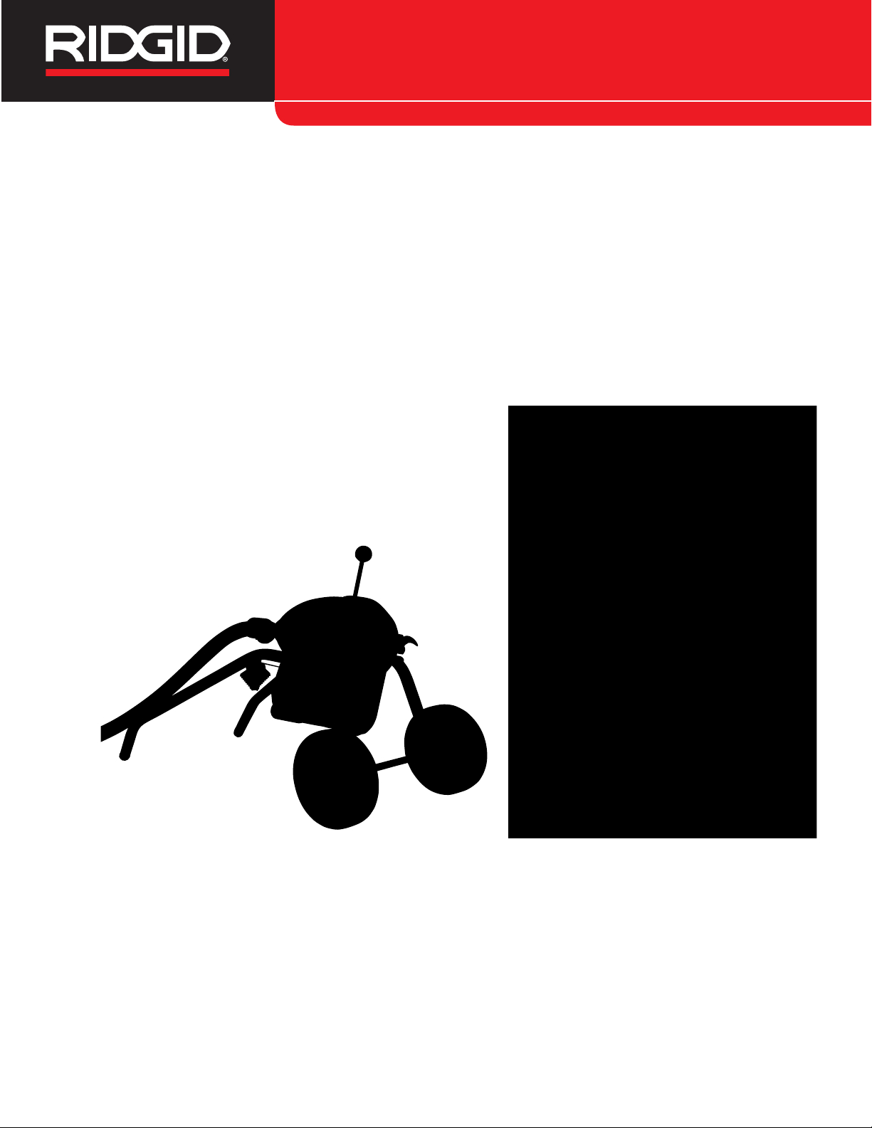
Drain Cleaner
Manual
K-1500A/B & K-1500SP
Drain Cleaning Machines
• Français – 15
• Castellano – pág. 33
Find Quality Products Online at: [email protected]
www.GlobalTestSupply.com
Page 2

K-1500A/B, & K-1500SP Drain Cleaning Machines
Table of Contents
Recording Form for Machine Serial Number ..............................................................................................................1
Safety Symbols ..............................................................................................................................................................2
General Power Tool Safety Warnings
Work Area Safety ........................................................................................................................................................2
Electrical Safety...........................................................................................................................................................2
Personal Safety ...........................................................................................................................................................3
Power Tool Use and Care ...........................................................................................................................................3
Service ........................................................................................................................................................................3
Specific Safety Information
Drain Cleaner Safety ...................................................................................................................................................4
RIDGID®Contact Information........................................................................................................................................4
Description, Specifications and Standard Equipment
Description ..................................................................................................................................................................5
Specifications ..............................................................................................................................................................5
Standard Equipment....................................................................................................................................................5
Machine Inspection .......................................................................................................................................................6
Machine Set-Up..............................................................................................................................................................6
Operating Instructions ..................................................................................................................................................8
Special Procedures
Reverse Operating Instructions...................................................................................................................................9
Cable Applications.......................................................................................................................................................9
Storing And Transporting Cable ..................................................................................................................................9
Accessories .................................................................................................................................................................10
Maintenance Instructions
Moving Parts Lubrication...........................................................................................................................................11
Clutch Jaws Lubrication ............................................................................................................................................11
Cables .......................................................................................................................................................................11
Clutch Jaw Replacement...........................................................................................................................................11
Removing Clutch End Play........................................................................................................................................12
V-Belt Adjustment......................................................................................................................................................12
Machine Storage..........................................................................................................................................................12
Service and Repair ......................................................................................................................................................12
Wiring Diagrams.....................................................................................................................................................13-14
EC Declaration of Conformity ..........................................................................................................Inside Back Cover
Lifetime Warranty..........................................................................................................................................Back Cover
*Original Instructions - English
278-104-421.10_REV. Aii
Find Quality Products Online at: [email protected]
www.GlobalTestSupply.com
Page 3
Drain Cleaner
K-1500A/B & K-1500SP
Drain Cleaning Machines
WARNING!
Read this Operator’s Manual
carefully before using this
tool. Failure to understand
and follow the contents of
this manual may result in
electrical shock, re and/or
serious personal injury.
Find Quality Products Online at: [email protected]
www.GlobalTestSupply.com
Drain Cleaning Machine
Record Serial Number below and retain product serial number which is located on nameplate.
Serial
No.
Page 4
K-1500A/B, & K-1500SP Drain Cleaning Machines
Safety Symbols
In this operator’s manual and on the product, safety symbols and signal words are used to communicate important safety
information. This section is provided to improve understanding of these signal words and symbols.
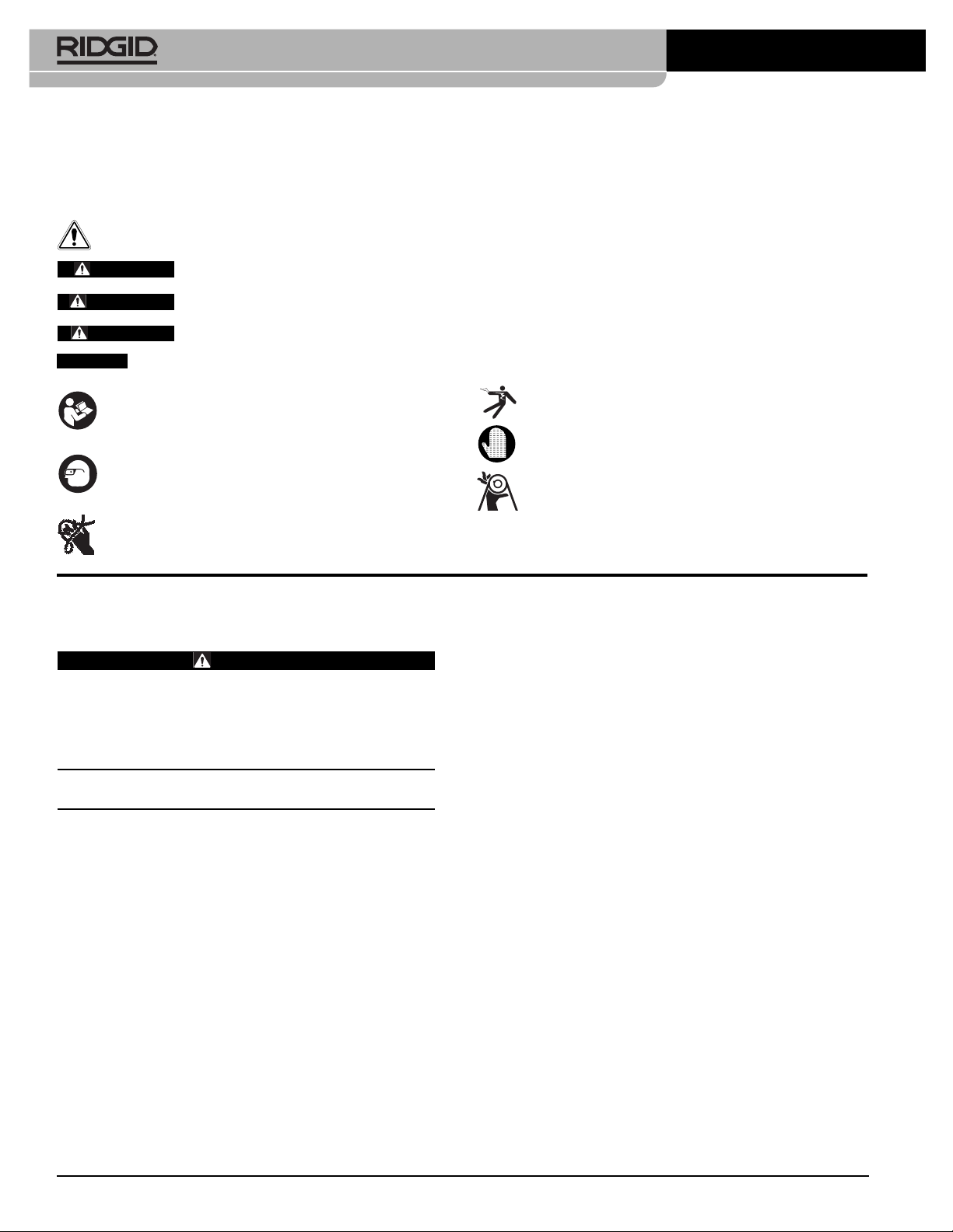
This is the safety alert symbol. It is used to alert you to potential personal injury hazards. Obey all safety messages that follow this
symbol to avoid possible injury or death.
DANGER
WARNING
CAUTION
NOTICE
NOTICE indicates information that relates to the protection of property.
This symbol means read the operator’s manual carefully
before using the equipment. The operator’s manual contains important information on the safe and proper
operation of the equipment.
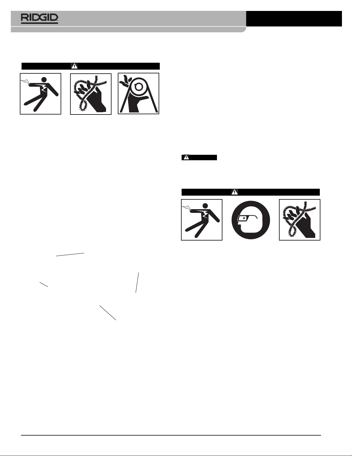
This symbol means always wear safety glasses with
side shields or goggles when handling or using this
equipment to reduce the risk of eye injury.
This symbol indicates the risk of hands, fingers or other
body parts being caught, wrapped or crushed in the
drain cleaning cable.
DANGER indicates a hazardous situation which, if not avoided, will result in death or serious injury.
WARNING indicates a hazardous situation which, if not avoided, could result in death or serious injury.
CAUTION indicates a hazardous situation which, if not avoided, could result in minor or moderate injury.
General Power Tool Safety
Warnings*
WARNING
Read all safety warnings, instructions, illustrations and specifications provided with this power
tool. Failure to follow all instructions listed below
may result in electric shock, fire, and/or serious injury.
SAVE ALL WARNINGS AND INSTRUCTIONS
FOR FUTURE REFERENCE!
The term "power tool" in the warnings refers to your
mains-operated (corded) power tool or battery-operated
(cordless) power tool.
Work Area Safety
• Keep work area clean and well lit. Cluttered or dark
areas invite accidents.
• Do not operate power tools in explosive atmo-
spheres, such as in the presence of flammable
liquids, gases, or dust. Power tools create sparks
which may ignite the dust or fumes.
• Keep children and by-standers away while operat-
ing a power tool. Distractions can cause you to lose
control.
This symbol indicates the risk of electrical shock.
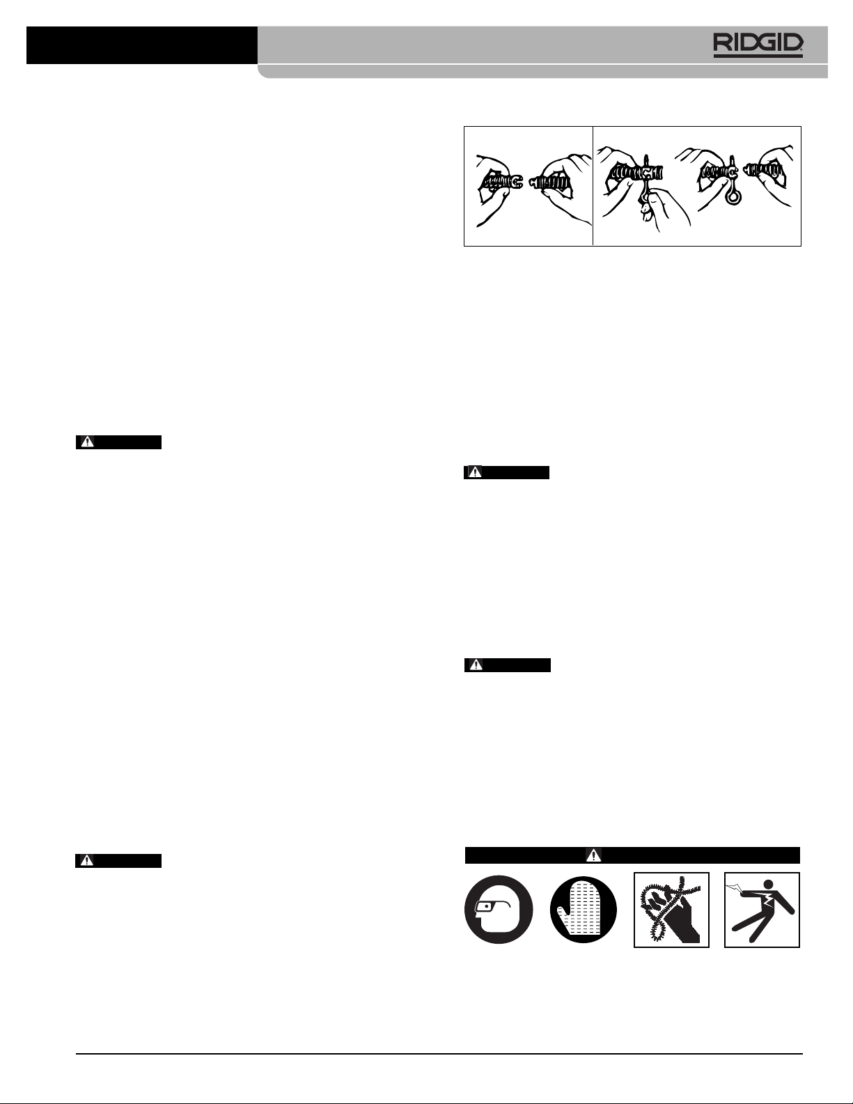
This symbol means always wear RIDGID drain cleaning
mitts while operating drain cleaner.
This symbol indicates the risk of entanglement in a belt
and pulley.
Electrical Safety
• Power tool plugs must match the outlet. Never
mod ify the plug in any way. Do not use any
adapter plugs with earthed (grounded) power
tools. Unmodi fied plugs and matching outlets will re-
duce risk of electric shock.
• Avoid body contact with earthed or grounded sur-
faces such as pipes, radiators, ranges and
refrigerators. There is an increased risk of electrical
shock if your body is earthed or grounded.
• Do not expose power tools to rain or wet condi-
tions. Water entering a power tool will increase the risk
of electrical shock.
• Do not abuse the cord. Never use the cord for
carrying, pulling or unplugging the power tool.
Keep cord away from heat, oil, sharp edges or
moving parts. Damaged or entangled cords increase
the risk of electric shock.
• When operating a power tool outdoors, use an
extension cord suitable for outdoor use. Use of a
cord suitable for outdoor use reduces the risk of electric shock.
• If operating a power tool in a damp location is un-
avoidable, use a ground fault circuit interrupter
* The text used in the General Power Tool Safety Warnings section of this manual is verbatim, as required, from the applicable UL/CSA/EN 62841-1 standard.
This section contains general safety practices for many different types of power tools. Not every precaution applies to every tool, and some do not apply to this
tool.
278-104-421.10_REV. A2
Find Quality Products Online at: [email protected]
www.GlobalTestSupply.com
Page 5
K-1500A/B, & K-1500SP Drain Cleaning Machines
(GFCI) protected supply. Use of a GFCI reduces the
risk of electric shock.
Personal Safety
• Stay alert, watch what you are doing and use common sense when operating a power tool. Do not
use a power tool while you are tired or under the influence of drugs, alcohol, or medication. A mo ment
of inattention while operating power tools may result in
serious personal injury.
• Use personal protective equipment. Always wear
eye protection. Protective equipment such as dust
mask, non-skid safety shoes, hard hat, or hearing
protection used for appropriate conditions will reduce
personal injuries.
• Prevent unintentional starting. Ensure the switch
is in the OFF position before connecting to power
source and/or battery pack, picking up or carrying
the tool. Carrying power tools with your finger on the
switch or energizing power tools that have the switch
ON invites accidents.
• Remove any adjusting key or wrench before turn-
ing the power tool ON. A wrench or a key left attached
to a rotating part of the power tool may result in personal injury.
• Do not overreach. Keep proper footing and balance
at all times. This enables better control of the power
tool in unexpected situations.
• Disconnect the plug from the power source and/or
the battery pack from the power tool before making
any adjustments, changing accessories, or storing
power tools. Such preventive safety measures re-
duce the risk of starting the power tool accidentally.
• Store idle power tools out of the reach of children
and do not allow persons unfamiliar with the power
tool or these instructions to operate the tool. Power
tools are dangerous in the hands of untrained users.
• Maintain power tools and accessories. Check for
misalignment or binding of moving parts, breakage
of parts and any other condition that may affect the
power tool’s op er ation. If damaged, have the power
tool repaired before use. Many accidents are caused
by poorly maintained power tools.
• Keep cutting tools sharp and clean. Properly main-
tained cutting tools with sharp cutting edges are less
likely to bind and are easier to control.
• Use the power tool, accessories and tool bits etc. in
accordance with these instructions, taking into account the working conditions and the work to be
performed. The use of the power tool for operations dif-
ferent from those intended could result in a hazardous
situation.
• Keep handles and grasping surfaces dry, clean
and free from oil and grease. Slippery handles and
grasping surfaces do not allow for safe handling and
control of the tool in unexpected situations.
• Dress properly. Do not wear loose clothing or jew-
elry. Keep your hair, and clothing away from
moving parts. Loose clothes, jewelry, or long hair
can be caught in moving parts.
• If devices are provided for the connection of dust
extraction and collection facilities, ensure these are
connected and properly used. Use of dust collection
can reduce dust-related hazards.
• Do not let familiarity gained from frequent use of
tools allow you to become complacent and ignore tool safety principles. A careless action can
cause severe injury within a fraction of a second.
Power Tool Use and Care
• Do not force power tool. Use the correct power
tool for your application. The correct power tool will
do the job better and safer at the rate for which it is designed.
• Do not use power tool if the switch does not turn it
ON and OFF. Any power tool that cannot be controlled with the switch is dangerous and must be
repaired.
Service
• Have your power tool serviced by a qualified repair
person using only identical replacement parts. This
will ensure that the safety of the power tool is maintained.
Specific Safety Information
WARNING
This section contains important safety information that is specific to this tool.
Read these precautions carefully before using the
K-1500 Drain Cleaners to reduce the risk of electrical shock or other serious injury.
SAVE ALL WARNINGS AND INSTRUCTIONS
FOR FUTURE REFERENCE!
Keep this manual with machine for use by the operator.
278-104-421.10_REV. A 3
Find Quality Products Online at: [email protected]
www.GlobalTestSupply.com
Page 6

K-1500A/B, & K-1500SP Drain Cleaning Machines
Drain Cleaner Safety
• Before using the tool, test the ground fault circuit interrupter (GFCI) provided with the power supply
cord to insure it is operating correctly. A properly
operating GFCI reduces the risk of electrical shock.
• Only use extension cords that are protected by a
GFCI. The GFCI on the machine power cord will not
prevent electrical shock from extension cords.
• Only grasp the rotating cable with gloves recom-
mended by the manufacturer. Latex or loose fitting
gloves or rags can become wrapped around the cable
and may result in serious personal injury.
• Do not allow the cutter to stop turning while the
cable is turning. This can overstress the cable and may
cause twisting, kinking or breaking of the cable and
may result in serious personal injury.
• One person must control both the cable and switch.
If the cutter stops rotating, the operator must be able to
turn the tool OFF to prevent the cable from twisting, kinking and breaking.
• Use latex or rubber gloves inside the gloves rec-
ommended by the manufacturer, goggles, face
shields, protective clothing, and respirator when
chemicals, bacteria or other toxic or infectious
substances are suspected to be in a drain line.
Drains may contain chemicals, bacteria and other substances that may cause burns, be toxic or infectious or
may result in other serious personal injury.
• Practice good hygiene. Do not eat or smoke while
handling or operating the tool. After handling or operating drain cleaning equipment, use hot, soapy
water to wash hands and other body parts exposed to drain contents. This will help reduce the risk
of health hazards due to exposure to toxic or infectious
material.
• Only use the drain cleaner for the recommended
drain sizes. Using the wrong size drain cleaner can lead
to twisting, kinking or breaking of the cable and may result in personal injury.
• Always use the rear guide hose while operating
the tool and ensure the cable does not extend beyond the rear guide hose. This prevents the cable
from whipping which may result in entanglement and
personal injury.
the drain inlet or properly support exposed cable
when the distance exceeds 2' (0.6 m). Greater dis-
tances can cause control problems leading to twisting,
kinking or breaking of the cable. Twisting, kinking or
breaking cable may cause striking or crushing injuries.
• One person must control both the cable and the
clutch. Do not lock clutch handle during operation. If the cutter stops rotating, the operator must be
able to release the clutch to prevent twisting, kinking and
breaking of the cable and reduce the risk of injury.
• Do not operate the machine in REV (reverse) rota-
tion except as described in this manual. Operating in
reverse can result in cable damage and is used to
back the cable end out of blockages.
• Do not wear loose clothing or jewelry. Keep your
hair and clothing away from moving parts. Loose
clothing, jewelry or hair can be caught in moving parts.
• Do not operate this machine if operator or machine
is standing in water. Operating machine while in
water increases the risk of electrical shock.
• Do not engage drain cleaner clutch (rotate cable)
while any part of the cable is in the cable carrier.
This may cause striking or crushing injuries.
• Operate machine from the side with the FOR/OFF/ -
REV Switch. Allows for better control of the machine.
• Never operate machine with belt guard removed.
Fingers can be caught between the belt and pulley.
• Do not use if there is the risk of contact with other
utilities (such as natural gas or electric) during operation. Visual inspection of the drain with a camera is
a good practice. Crossbores, improperly placed utilities
and damaged drains could allow the cutter to contact
and damage the utility. This could cause electrical
shock, gas leaks, fire, explosion or other serious damage or injury.
• Read and understand these instructions and the in-
structions and warnings for all equipment and
materials being used before operating this tool to
reduce the risk of serious personal injury.
• Keep mitt-covered hand on the cable whenever the
machine is running. This provides better control of the
cable and helps prevent twisting, kinking and breaking
of the cable and may result in serious personal injury.
• Position machine cable outlet within 2' (0.6 m) of
278-104-421.10_REV. A4
Find Quality Products Online at: [email protected]
www.GlobalTestSupply.com
Page 7

K-1500A/B, & K-1500SP Drain Cleaning Machines
Description, Specifications and
Standard Equipment
Description
The RIDGID®K-1500A/B & K-1500SP Drain Cleaning
Machines are for cleaning 2" through 10" lines. These machines are driven by induction motors that have a grounded
electrical system. An integral Ground Fault Interrupter
(GFCI) is built into the line cord. A toggle or rotary switch provides FORWARD/OFF/REVERSE control of the motor.
Machines are designed to use sectional-type cable that
has a quick coupling system for disconnecting tools. The
cable is manually fed in and out of the machine and rotates
at a cable speed of 600 to 700 RPM. The rotation of the
cable is controlled by a clutch handle. The cable stops instantly when the clutch handle is released.
K-1500 machines come equipped to run 11/4" cable to
clean 3" – 10" lines through 200' – the 1500SP through
300'. They can be easily adapted to use 7/8" cable to clean
2" – 4" lines.
Specifications
Line Capacity ...............Depends on choice of cable.
Refer to the following chart for
recommendations.
Motor
K-1500A/B
Type ............................115V/60Hz, Reversible, 230V-
240V/50Hz Versions Available
Upon Request
Rating ..........................3/4HP
Amps ...........................10.4
K-1500A/B-SP
Type ............................115V/240V/50-60Hz,
Reversible,Total Enclosed Fan
Cooled
Rating ..........................1 HP
Amps ...........................15
Sound Pressure (LPA)* ......68.4 dB(A), K=3
Sound Power (LWA)*...........77 dB(A), K=3
* Sound measurements are measured in accordance with a standardized test per
Standard EN 62841-1.
- Sound emissions may vary due to your location and specific use of these tools.
- Daily exposure levels for sound need to be evaluated for each application and appropriate safety measures taken when needed. Evaluation of exposure levels
should consider the time a tool is switched off and not in use. This may significantly reduce the exposure level over the total working period.
K-1500A/B-SP
A Style .........................2 Wheels In Rear w/Upright
Handle On Frame Assembly
and Cable Storage Capacity
B Style .........................2 Wheels In Front On
FrameAssembly.
See the RIDGID Catalog for machine model options and
accessories. Every machine model includes as standard
equipment:
Standard Equipment
• A-1 Operator’s Mitt
• A-12 Pin Key
• A-34-12 Rear Guide Hose
Clutch
Handle
Guide
Tool
Figure 1 – K-1500A and K-1500SPA Drain Cleaners
Hose
FOR/OFF/REV
Switch
Chart 1
Model Frame Cable Capacity Overall Machine
No. Style Size Line Reach Horsepower Height Width Length Wt. Lbs.
K-1500A
K-1500A-SE
K-1500B
K-1500B-SE
K-1500SP B
K-1500SPA A1
A
B1
7
/8" 2" - 4" 175'
or
1
/4" 3" - 10" 200' 273/4" 203/4" 405/8" 80
7
/8" 2" - 4" 175' 1HP at 600 RPM 273/4" 203/4" 405/8" 110
1
/4" 3" - 10" 300' 411/2" 203/4" 16" 138
3
/4HP at 710 RPM
1
/2" 203/4" 16" 92
41
278-104-421.10_REV. A 5
Find Quality Products Online at: [email protected]
www.GlobalTestSupply.com
Page 8
K-1500A/B, & K-1500SP Drain Cleaning Machines
Machine Inspection
WARNING
To prevent serious injury, inspect your Drain Clean ing Machine. The following inspection procedures
should be performed before each use.
1. Make sure the Drain Cleaning Machine is unplugged
and the directional switch is set to the OFF position
(Figures 1 and 2).
2. Inspect the power cord, Ground Fault Circuit Inter rupter (GFCI) and plug for damage. If the plug has
been modified, is missing the grounding prong or if the
cord is damaged, do not use the Drain Cleaning
Machine until the cord has been replaced.
3. Inspect the Drain Cleaning Machine for any broken,
missing, misaligned or binding parts as well as any
other conditions which may affect the safe and normal
operation of the machine. If any of these conditions
are present, do not use the Drain Cleaning Machine
until any problem has been repaired.
Clutch
Handle
Guide
Hose
Tool
use with other equipment may be hazardous when
used with this drain cleaner.
6. Clean any oil, grease or dirt from all equipment handles and controls. This reduces the risk of injury due
to a tool or control slipping from your grip.
7. Inspect the cutting edges of your tools. If necessary,
have them sharpened or replaced prior to using the
Drain Cleaning Machine. Dull or damaged cutting
tools can lead to binding and cable breakage.
8. Inspect cables and couplings for wear and damage.
Cables should be replaced when they become
severely worn or corroded. A worn cable can be
identified when the outside coils become flat.
WARNING
Worn or damaged cables can break caus-
ing serious injury.
Machine Set-Up
WARNING
Do not place machine in water. Water entering
the motor can result in electrical shock.
To prevent serious injury, proper set-up of the
machine and work area is required. The following
procedures should be followed to set-up the machine:
1. Check work area for:
• Adequate lighting
• Grounded electrical outlet
• Clear path to the electrical outlet that does not
FOR/OFF/REV
Switch
contain any sources of heat or oil, sharp edges or
moving parts that may damage electrical cord.
• Dry place for machine and operator. Do not use the
machine while standing in water.
• Flammable liquids, vapors or dust that may ignite.
Figure 2 – K-1500B and K-1500SP Drain Cleaning
Machines
2. Position the Drain Cleaning Machine within 2' of
sewer inlet. Greater distance can result in cable twisting or kinking.
4. Lubricate the Drain Cleaning Machine, if necessary,
according to the Maintenance Instructions.
3. Make sure FOR/OFF/REV switch is in the OFF position.
5. Use tools and accessories that are designed for your
drain cleaner and meet the needs of your application.
The correct tools and accessories allow you to do the
job successfully and safely. Accessories suitable for
278-104-421.10_REV. A6
Find Quality Products Online at: [email protected]
www.GlobalTestSupply.com
Page 9
K-1500A/B, & K-1500SP Drain Cleaning Machines
Figure 3 – Rear Guide Hose Attachment
4. Attach the rear guide hose by sliding guide hose
adapter onto the guide hose pins (Figure 3).
WARNING
Do not use machine without rear guide
hose attached. Prevents cable whipping and possible entanglement and a cleaner job site.
5. Insert first cable into front of machine (female end
first) and push through guide hose until approximately one foot remains out the front of the machine
(Figure 4).
To Couple Cable
and Tools
Snap Together Insert Pin Slide Apart
Figure 5 – Coupling and Uncoupling Tools
NOTE! Proper Tool Selection
To Uncouple Cable and Tools
A good rule of thumb is to use a tool at least 1"
smaller than the line to be cleaned. The style of the
tool is determined by the nature of the job and is
left up to the operator.
7. Plug the Drain Cleaning Machine into the electrical
outlet, making sure to position the power cord along
the clear path selected earlier. If the power cord
does not reach the outlet, use an extension cord in
good condition.
WARNING
To avoid electric shock and electrical
fires, never use an extension cord that is damaged or
does not meet the following requirements:
• The cord has a three-prong plug similar to the de-
scription in the Electrical Safety section.
• The cord is rated as “W” or “W-A” if being used out-
doors.
• The cord has sufficient wire thickness (14 AWG - 50').
If the wire thickness is too small, the cord may overheat,
melting the cord’s insulation or causing nearby objects
to ignite.
WARNING
To reduce risk of electrical shock, keep
all electrical connections dry and off the ground. Do
not touch plug with wet hands. Test the Ground Fault
Circuit Interrupter (GFCI) provided with the electric cord
to insure it is operating correctly. When test button is
pushed in, the indicator light should go OFF. Reactivate
by pushing the reset button in. If indicator light goes ON,
the machine is ready to use. If the GFCI does not function correctly, do not use the machine.
Figure 4 – Inserting Cable Into Front Of Machine
WARNING
Never couple more than one cable at a
Operating Instructions
WARNING
time. Cable will extend behind rear guide tube.
6. Select and install the proper tool to the end of the
cable. The T-Slot Coupler allows the tool to be snapped
into the cable coupler (Figure 5). To remove tool, use
the pin key to depress the plunger and slide the coupling apart.
Wear mitts with rivets provided with machine.
Never grasp a rotating cable with a rag or loose fitting cloth that may become wrapped around the
cable causing serious injury.
Always wear eye protection to protect your eyes
278-104-421.10_REV. A 7
Find Quality Products Online at: [email protected]
www.GlobalTestSupply.com
Page 10

K-1500A/B, & K-1500SP Drain Cleaning Machines
against dirt and other foreign objects. Wear rubber
soled, non-slip shoes.
Be very careful when cleaning drains where cleaning compounds have been used. Wear gloves when
handling cable and avoid direct contact to the
skin and especially the eyes and facial area as serious burns can result.
Do not operate with clutch handle locked in place.
Clutch is a safety feature designed to stop rotation
of cable when released.
CAUTION
It is very important to know approximate distance from inlet to main sewer or septic tank. Over-running
cable too far into main sewer or septic tank can cause cables to knot up and prevent their return through small
lines. If main is 12 inches or larger and standard 11/4"
cable is being used, do not allow more than 10 to 15 feet of
overrun. When working into a septic tank do not allow
more than 3 to 5 feet overrun.
1. Assume the correct operating posture in order to
maintain proper balance (Figure 6).
WARNING
Should an unexpected situation arise, this
posture provides you with the opportunity to safely keep
control of the machine and cable.
• Be sure you can quickly release the clutch handle.
• Hand must be on the cable to control its twisting
action when it hits an obstruction.
• Must have access to FOR/OFF/REVERSE switch.
3. Pull enough extra cable through machine to form almost a half circle between machine and line opening.
4. Hold cable loosely in mitted hand. Put FOR/OFF/REVERSE switch in FOR (forward) position.
NOTE! The motor will start but cable will not rotate.
5. With mitted hand on cable, push down on clutch handle with opposite hand to engage cable. Push down
on top of the cable loop with a definite snap to advance the cable.
NOTE! A slow or gradual engaging of the clutch handle
causes excessive wear of the jaw set. The clutch
is instant-acting and returning clutch handle to its
original position frees cable instantly.
6. As soon as excess cable has gone into line, release
clutch handle and pull six to ten inches of cable out of
machine with mitted hand.
7. Continue to feed the cable into the line until resistance
or obstruction is encountered. This will become apparent to operator as it will be difficult to feed additional
cable into line and/or the cable will have a tendency to
twist sideways in operator’s hands.
8. If cable loads down in the obstruction, relieve load by
pulling back on cable with short, quick jerks to free
cutter. Slowly advance cable back into the obstruction. Repeat this process until the obstruction is clear.
Remember, make sure the cutter is rotating at all
times and never force the cable. At this point, pro gress depends upon the sharpness of the tool and
nature of the obstruction.
WARNING
Do not allow tension to build up in the cable. This
will happen if the cutting tool hits a snag and stops
turning, but the motor and cable continue to rotate. Torque builds until the cable suddenly twists,
potentially wrapping around your hand or arm. This
can happen quickly and without warning, so proceed
slowly and carefully as you feed the cable into the
drain. Releasing clutch handle will stop the cable rotating and releases the torque. If tool gets hung
up in an obstruction, refer to Reverse Operating
Instructions in the “Special Procedures” section.
9. Once obstruction is cleared, it is recommended that operator flush debris from line with running water. Repeat
Step 8 several times if necessary for thorough cleaning job and then work cable through additional stop -
Figure 6 – Proper Operating Position
2. Pull sufficient cable out of the machine to start tool and
cable into the sewer inlet. Push cable into inlet as far
as it will go.
pages as required.
10. To add cable, the following procedure should be followed:
• After reaching the end of each cable section, turn
the machine OFF.
278-104-421.10_REV. A8
Find Quality Products Online at: [email protected]
www.GlobalTestSupply.com
Page 11
K-1500A/B, & K-1500SP Drain Cleaning Machines
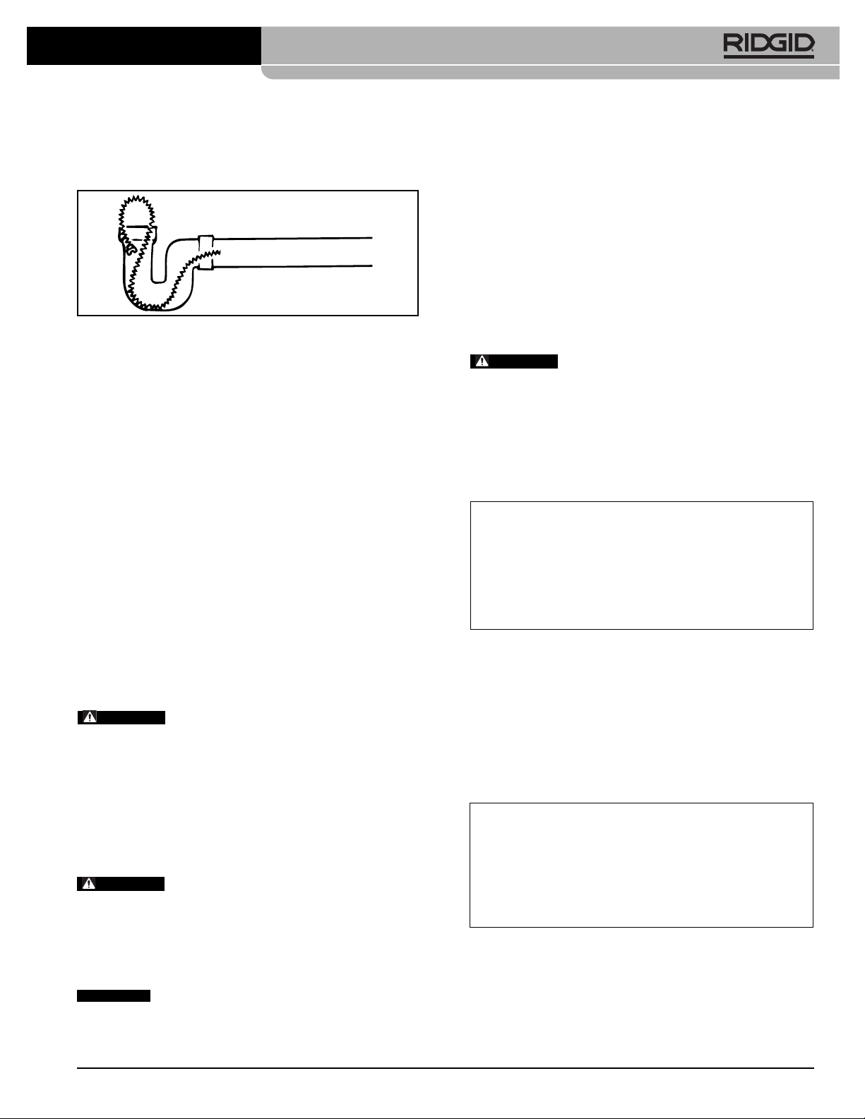
• Secure the cable by looping it in the line (Figure 7).
This procedure is especially useful when cleaning
a line with a steep grade.
Figure 7 – Looping Cable In Line
• With line secured, insert another section of cable
in through the front of the machine (female end
first) until approximately one foot remains out the
front of the machine.
• Attach cable to cable in line and resume operation.
11. To retrieve cable from drain line, the following procedure should be followed:
• Leave FOR/OFF/REV switch in FOR (FORWARD)
position.
• Push down on clutch handle to engage cable.
With mitted hand pull cable out of line (if possible)
or hold cable against edge of inlet to thread the
cable out until loop forms in front of the machine.
NOTE! By holding the cable against the edge of the
inlet, the rotation will rapidly “thread” the cable out
of the line.
• When loop forms, release clutch handle and push
excess cable back through machine. Disconnect
one section at a time.
WARNING
When disconnecting sections, remem-
ber to turn unit OFF and secure cable in line.
• Once section of cable is removed, insert the se-
cured cable in through the front of the machine and
continue removing sections until tool on last section
of cable is just inside sewer inlet.
HINT! When placing removed cables back into cable
carrier, reconnect all cables. This assures easy
removal at next job.
WARNING
Never retract tool from sewer inlet while
cable is rotating. Tool can whip causing serious injury.
12. Turn FOR/OFF/REV Switch to OFF position.
13. Pull remaining cable and tool from sewer.
Special Procedures
Reverse Operation
Running machine in reverse will cause premature failure of
cable. Use reverse only to free a tool caught in an obstruction. If this should occur, immediately release clutch
handle and place FOR/OFF/REV switch to OFF position.
After motor comes to a complete stop, place FOR/OFF/ REV switch in the REV (REVERSE) direction. Engage
clutch handle only until tool is free of obstruction. Once tool
is free, release clutch handle immediately. Turn unit OFF.
Run unit in FOR (FORWARD) direction and follow normal
operating procedure.
WARNING
VERSE) for any other purpose. Operating in reverse
can damage a cable and cause serious injury.
Cable Applications
Standard Cable: Standard 7/8" or 11/4" cable can be used in
straight lines from 3" through 6" and through fittings. (Figure
8)
4" and 6" Tees
Figure 8 – Standard Cable Application
Heavy-Duty Cable: Where conditions allow, heavy-duty 11/
inch cable, such as C-14, should be used for faster results
and longer cable life. The heavy-duty cables work effectively
in 4" through 8" straight lines. (Figure 9)
NOTE! This type cable should not be used in areas
6" to 8"
Running Traps
Figure 9 – Heavy Duty Cable Application
Never operate this machine in REV (RE-
3", 4" and 6" Y’s
3", 4" and 6" Ells
where 4" “P” traps or 4" running traps are currently in use.
4" to 8" Ells
4" to 8"
Cleanouts
4
14. Unplug power cord and remove guide hose.
CAUTION
After using, thoroughly flush and drain cables,
couplings and tools with water due to damaging effects of
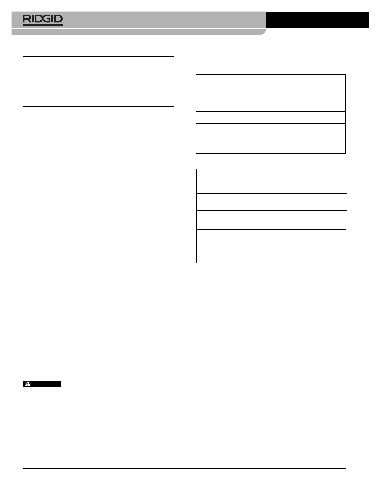
Faster Cleaning: Obstructions of grease or fats can be
cleaned faster and more effectively by bending the cable
some 6" or 8" behind the cutter. (Figure 10)
some drain cleaning compounds.
278-104-421.10_REV. A 9
Find Quality Products Online at: [email protected]
www.GlobalTestSupply.com
Page 12
K-1500A/B, & K-1500SP Drain Cleaning Machines
Bent Cable
Figure 10 – Bending Cable for Faster Cleaning
Storing And Transporting Cable
(“A” Frame Models Only)
Cables can be stored and transported on “A” frame
models as shown in Figure 11.
K-1500A/B Machines
Cables and Leaders
Catalog Model
No. No. Description
92280 C-11 15' Standard All-Purpose Wind,
62285 C-12 15' Extra-Heavy-Duty Wind,
62295 C-14 15' Heavy-Duty Wind,
62300 C-15 15' Extra-Flexible Wind,
63090 T-27 1
62275 C-10 15' Standard All-Purpose Wind,
Accessories
Catalog Model
No. No. Description
59470 A-8 Cable Carrier, 60' Capacity (1
59210 A-10 Cable Carrier, 150' Capacity (1
59415 A-34-10 10' Rear Guide Hose
59395 A-34-12 12' Rear Guide Hose
59400 A-34-16 16' Rear Guide Hose
59300 A-20 8' Front Guide Hose Assembly
59205 A-1 Left-Hand Mitt
59295 A-2 Right-Hand Mitt
59360 A-3 Tool Box
59225 A-12 Coupling Pin Key
59440 A-4 Trap Spoon (30")
59240 A-17 Manhole Guide Pipe
59320 A-369X 1
Good for 4" Traps, 3" - 8" Lines.
4" - 10" Long Runs, No 4" Traps.
Through Cleanout, No 4" Traps.
Good for Traps.
1
/4" x 25' Leader
Requires A-368X Jawset
1
/4" Replacement Jawset
1
/2" Pitch. 3" - 10" Lines
1
/2" Pitch. 3" - 6" Lines
3
/8" Pitch.
7
/8" Tools
3
/8" Pitch.
1
/4")
1
/4")
Figure 11 – Storing Cables On “A” Frame Models
Accessories
WARNING
been designed to function with the Sectional Drain Clean ing Machines. Other accessories suitable for use with
other tools may become hazardous when used on the machines. To prevent serious injury, use only the recom mended accessories.
Find Quality Products Online at: [email protected]
Only the following RIDGID products have
278-104-421.10_REV. A10
www.GlobalTestSupply.com
Page 13
K-1500A/B, & K-1500SP Drain Cleaning Machines
Tools for C-11, C-12, C-14 and C-15 Cables 11/4"
Catalog Model
No. No. Description
62840 T-1 Straight Auger
61800 T-2 Heavy-Duty Straight Auger
63105 T-3 Funnel Auger
61790 T-4 Heavy-Duty Funnel Auger
63190 T-5 Straight Retrieving Auger
63195 T-6 Funnel Retrieving Auger
63200 T-7 Hook Auger
63205 T-8 Grease Cutter, 2
63210 T-9 Grease Cutter, 3
62845 T-10 Grease Cutter, 4
59480 T-11 “H” Cutter, 2
59485 T-12 “H” Cutter, 3
61970 T-13 Sawtooth Cutter, 2
61975 T-14 Sawtooth Cutter, 3
61770 T-15A Expanding Cutter, 4" - 6"
61825 T-15B Expanding Cutter, 6" - 8"
61960 T-16 Spiral Bar Cutter, 4"
61850 T-17 Spiral Bar Cutter, 6"
61855 T-18 Spiral Bar Cutter, 8"
59625 T-21 Spiral Sawtooth Cutter, 2
63075 T-22 Spiral Sawtooth Cutter, 3"
63085 T-23 Spiral Sawtooth Cutter, 4"
59765 T-24 4-Blade Cutter, 2
59770 T-25 4-Blade Cutter, 3
59775 T-26 4-Blade Cutter, 4
59780 T-26A 4-Blade Cutter, 5
98030 T-50 Includes 3 Sizes: 3" − 4"− 5"
98035 T-50-1 Sharktooth Cutter, 3"
98040 T-50-2 Sharktooth Cutter, 4"
98045 T-50-3 Sharktooth Cutter, 6"
63110 T-31 Chain Knocker, 3" − 4" Pipe
63115 T-32 Chain Knocker, 6" Pipe
63120 T-33 Chain Knocker, 8" Pipe
63145 T-38 Flue Brush, 1
63150 T-39 Flue Brush, 2"
63155 T-40 Flue Brush, 2
63160 T-41 Flue Brush, 3"
63165 T-42 Flue Brush, 3
63170 T-43 Flue Brush, 4"
63175 T-44 Flue Brush, 4
63240 T-45 Flue Brush, 5"
63180 T-46 Flue Brush, 5
63185 T-47 Flue Brush, 6"
1
/2"
1
/2"
1
/2"
1
/2"
1
/2"
1
/2"
1
/2"
1
/2"
1
/2"
1
/2"
1
/2"
1
/2"
1
/2"
1
/2"
1
/2"
1
/2"
1
/2"
NOTE! See RIDGID Catalog for complete list of tools
and accessories.
Maintenance Instructions
WARNING
Make sure machine is unplugged from power source
before performing maintenance or making any adjustment.
Moving Parts Lubrication
Grease all exposed moving parts such as rocker arms
and main bearing approximately every three months.
Make sure to grease main bearing thru grease fitting inside clutch handle slot.
Clutch Jaws Lubrication
Clean and lubricate clutch driver jaws with oil after each
use.
Cables
Cables should be thoroughly flushed with water to prevent damaging effects of sediment and drain cleaning
compounds. Periodically lubricate cables and couplings
with RIDGID Cable Rust Inhibitor.
When not in use, store cables indoors to prevent deterioration by the elements.
Cables should be replaced when they become severely
corroded or worn. A worn cable can be identified when
outside coils of cable become flat.
Clutch Jaws Replacement
1. Remove four screws holding the front guard to the
housing.
2. Remove screws from the nose piece assembly (Figure
12).
Figure 12 – Replacing Clutch Jaws
278-104-421.10_REV. A 11
Find Quality Products Online at: [email protected]
www.GlobalTestSupply.com
Page 14
K-1500A/B, & K-1500SP Drain Cleaning Machines
3. Slide out clutch driver jaws and replace with desired
size jaws.
Figure 13 – Replacing Clutch Jaws
4. Replace nose piece assembly, screws and guard.
WARNING
re moved. Fingers can be caught between the belt and
pulley.
Never operate machine with belt guard
Removing Clutch End Play
1. To remove end play from clutch, loosen screw in
Adjusting Nut. (Figure 14).
2. Turn lock and adjusting nut clockwise until snug
against housing, then back off one half turn.
3. Tighten screw in lock and adjusting nut.
V-Belt Adjustment
Check V-Belt periodically for loosening. V-Belt should be
kept tight at all times.
1. To tighten V-Belt remove Guard.
2. Loosen locknut, turn adjusting bolt slowly until VBelt stiffens, tighten locknut. (Figure 15).
Locknut
Figure 15 – Adjusting V-Belt Tension
Machine Storage
WARNING
doors or well covered in rainy weather. Store the
machine in a locked area that is out of reach of children
and people unfamiliar with drain cleaners. This machine can cause serious injury in the hands of untrained
users.
If machine has been exposed to freezing weather, unit
must be run for ten (10) to twenty (20) minutes without
load to warm up. Failing to do this will result in frozen
bearings. If machine is exposed to weather for a period
of time, moisture will form across motor windings causing motor to burn out.
Motor-driven equipment must be kept in-
Service and Repair
WARNING
The “Maintenance Instructions” will take care of most of
Figure 14 – Removing Clutch End Play
Find Quality Products Online at: [email protected]
www.GlobalTestSupply.com
the service needs of this machine. Any problems not addressed by this section should only be handled by an
authorized RIDGID service technician.
278-104-421.10_REV. A12
Page 15

WARNING
K-1500A/B, & K-1500SP Drain Cleaning Machines
Tool should be taken to a RIDGID Independent Auth orized Service Center or returned to the factory. All repairs
made by Ridge Tool service facilities are warranted against
defects in material and workmanship.
When servicing this machine, only identical replacement parts should be used. Failure to follow
these instructions may create a risk of electrical shock or
other serious injury.
K-1500A/B Wiring Diagram
115V
Green
Motor
Blue
Red
Black
Yellow
Green
White
Black
Switch
278-104-421.10_REV. A 13
Find Quality Products Online at: [email protected]
www.GlobalTestSupply.com
Service Cord
Page 16

K-1500A/B, & K-1500SP Drain Cleaning Machines
K-1500SP Wiring Diagram
120V/60 Hz
Ground
Screw in
Switchbox
Bk
O
W
Bl
R
Y
Green
L2 White
L1 Black
Service Cord
K-1500SP Wiring Diagram
For
L1
L2
W
W
Y
Line cord Modification:
Cut off existing terminals
Strip Wire Ends .25 in.
U1
U2
Bl
Rev
Switch
Bk
RevBkFor
1
Z1
Green
White
R
Black
220-240V/50 Hz
R
W
Bk
O
Y
Bl
Green-Yellow
L2 Brown
L1 Blue
Ground
Screw in
Switchbox
Switch
RevBkFor
Y
Line cord Modification:
Strip Wire Ends .25 in.
Bl Br
For Rev
L2 L1
NOTE: Switch modified using
provided jumper terminals.
Bl
Green-Yellow
Brown
Blue
278-104-421.10_REV. A14
Find Quality Products Online at: [email protected]
www.GlobalTestSupply.com
 Loading...