


350 S. St. Charles St. Jasper, In. 47546
Ph. 812.482.2932 Fax 812.634.6632
www.ridetech.com
Part # 13076799
02-05 Dodge ½ ton Airbar
Components:
2 90002019 Rolling sleeve air spring
2 90000119 Air spring roll plate
1 90000426 Passenger front upper bar frame bracket
1 90000425 Driver side front upper bar frame bracket
1 90000427 Upper bridge assembly
2 90000044 Lower bridge upper axle bracket
1 90000232 Lower bridge assembly
1 90000442 Passenger side upper shock mounting plate
1 90000441 Driver side upper shock mounting plate
1 90000230 Panhard bar axle mount
2 90000994 Upper bar – TW 30.75” (CC= 32.50”)
2 90001036 Lower bars – WW 32.5” (Uses factory Leaf spring bolt)
1 90000969 Panhard bar – TW20.187” (CC= 22 1/16”)
2 90001617 .625” shock studs (Lower shock mount)
4 90001085 Lower bar forward mount bushings
2 90001094 Inner bushing sleeves – Installed in front of lower bar
5 90001942 Rubber bushings pressed into bars and rod ends
2 90001584 Threaded rod end
1 90001589 Kevlar lined Heim end
3 99752004 ¾” SAE jam nut
2 90001082 Short bump stops
1 99010012 Hardware Kit

350 S. St. Charles St. Jasper, In. 47546
Ph. 812.482.2932 Fax 812.634.6632
www.ridetech.com
Hardware Kit – Part # 99010012
2 ½ X 2 ½ Gr. 5 USS Bolts Upper Shock Mount
2 ½ USS Gr. 5 Nyloc Nuts Upper Shock Mount
6 5/16 X 1 ½ USS Gr. 5 Bolts Panhard Bar Axle Mount
6 5/16 SAE Lock washers Panhard Bar Axle Mount
6 5/16 SAE Flat washers Panhard Bar Axle Mount
8 5/8 x 6 ½ SAE Gr.8 Bolts Lower Bridge to Axle
8 5/8 SAE Gr.8 Nyloc Nuts Lower Bridge to Axle
16 5/8 SAE Gr.8 Flat washers Lower Bridge to Axle
8 7/16 X 1 Gr.5 USS Bolts Front Upper Bar Mounts to Frame
8 7/16 Gr.5 USS Nyloc Nuts Front Upper Bar Mounts to Frame
16 7/16 Gr.5 SAE Flat washers Front Upper Bar Mounts to Frame
1 5/8 X 2 ½ SAE Gr.8 Bolts Panhard bar to rearend bracket
2 5/8 SAE Gr.8 Flat washers Panhard bar to rearend bracket
1 5/8 SAE Gr.8 Lock washer Panhard bar to rearend bracket
7 5/8 X 2 ¾ SAE Gr.8 Bolts Bar ends to brackets
7 5/8 SAE Gr.8 Thin Nyloc Nuts Bar ends to brackets
4 3/8 X 1 Gr.5 USS Bolts Air spring Mounting
20 3/8 Gr.5 SAE Flat washers Air spring, Bridge, and Shock mounting
20 3/8 Gr.5 SAE Lock washers Air spring, Bridge, and Shock mounting 18 3/8 X
1 Self Tapping Bolts Upper Bridge and Shock Bracket
*NOTE - Drill hole to 5/16” for self tapping bolts.
Installation Instructions
1. Raise vehicle to a safe and comfortable working height supported by jack stand. Let the
suspension hang freely.
2. Remove the leaf springs and shocks while supporting axle.
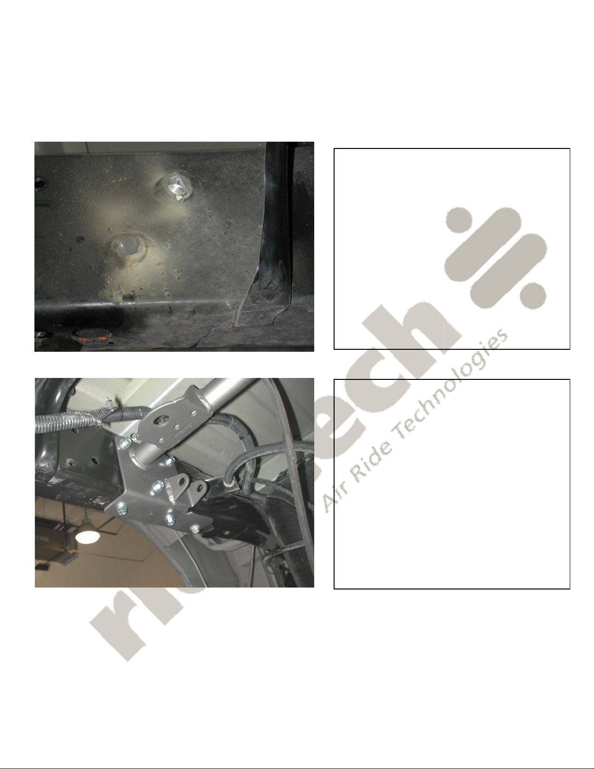
1. The factory exhaust hangers need to
be cut off and ground smooth for upper
bridge clearance.
2. Drill and tap a 3/8”-16 hole directly in
the center of the two OEM bump stop
holes. This is the location for your new
shorter bump stop.
3. Install the upper bridge assembly
between frame rails. The bridge will be
indexed by the front hole in the bottom of
the bridge aligning with the rear OEM
bump stop hole. Drill the remaining 5
holes with a 5/16 drill bit. Secure with
supplied 3/8” x 1” self-tapping bolts.
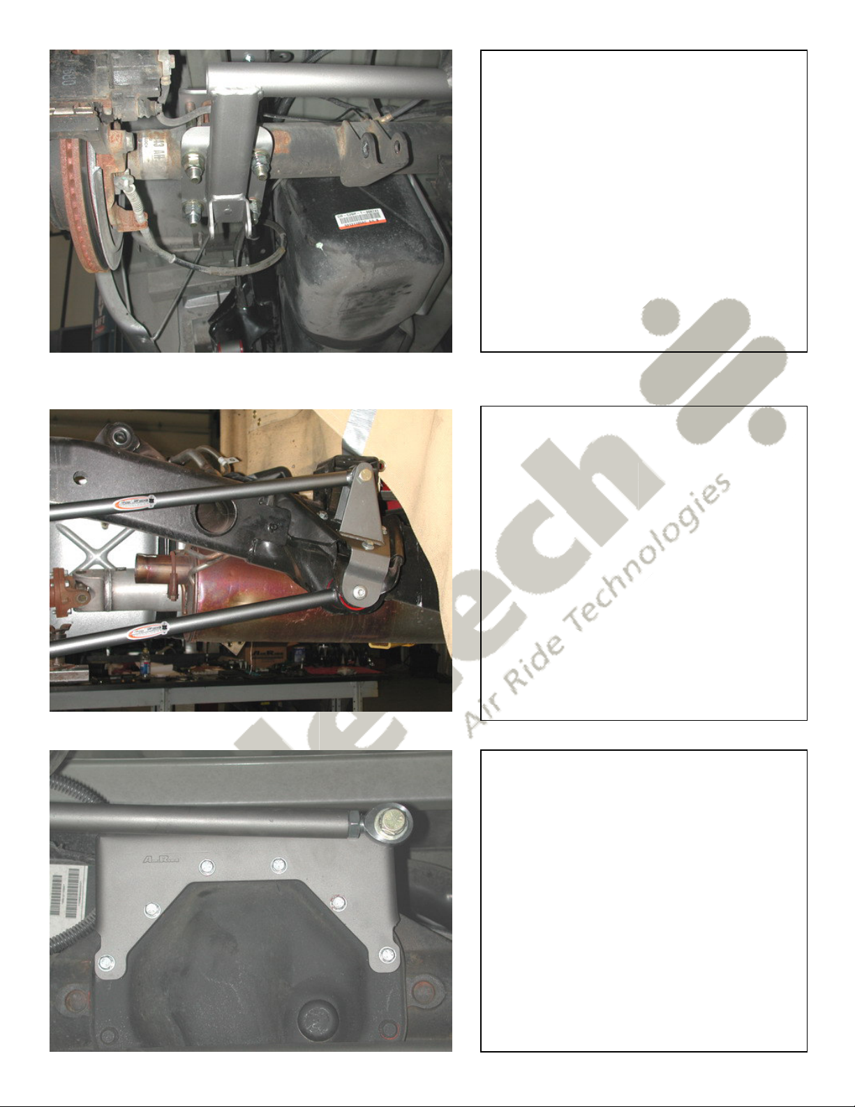
4. Bolt lower bridge assembly to axle
using 5/8” x 6-1/2” bolts.
The bolt in the upper bracket will align
the bridge with leaf spring alignment pin.
Tighten the bolts evenly.
5. Align frame bracket with the hole in
the leaf spring hanger. Drill remaining 2
holes. Use the 7/16” x 1” bolts to
secure.
6. Install upper and lower bars using the
5/8” x 2-3/4” bolts supplied. The lower
front bar uses the factory bolt. The
upper bar is slightly shorter.
Note: The exhaust may need to be
modified, or a turndown may be
installed.
7. Remove the top 6 bolts on the axle
cover. Place the panhard bar axle
bracket over these 6 holes and tighten
the 5/16” x 1-1/2” bolts supplied to
factory specs.
8. Attach the panhard bar Heim end to
the axle bracket using the 5/8 x 2-1/2”
bolt. Use the 5/8 x 2-3/4” to fasten the
rubber end to upper bridge.
Note: The axle vent tube may need to
be shortened.
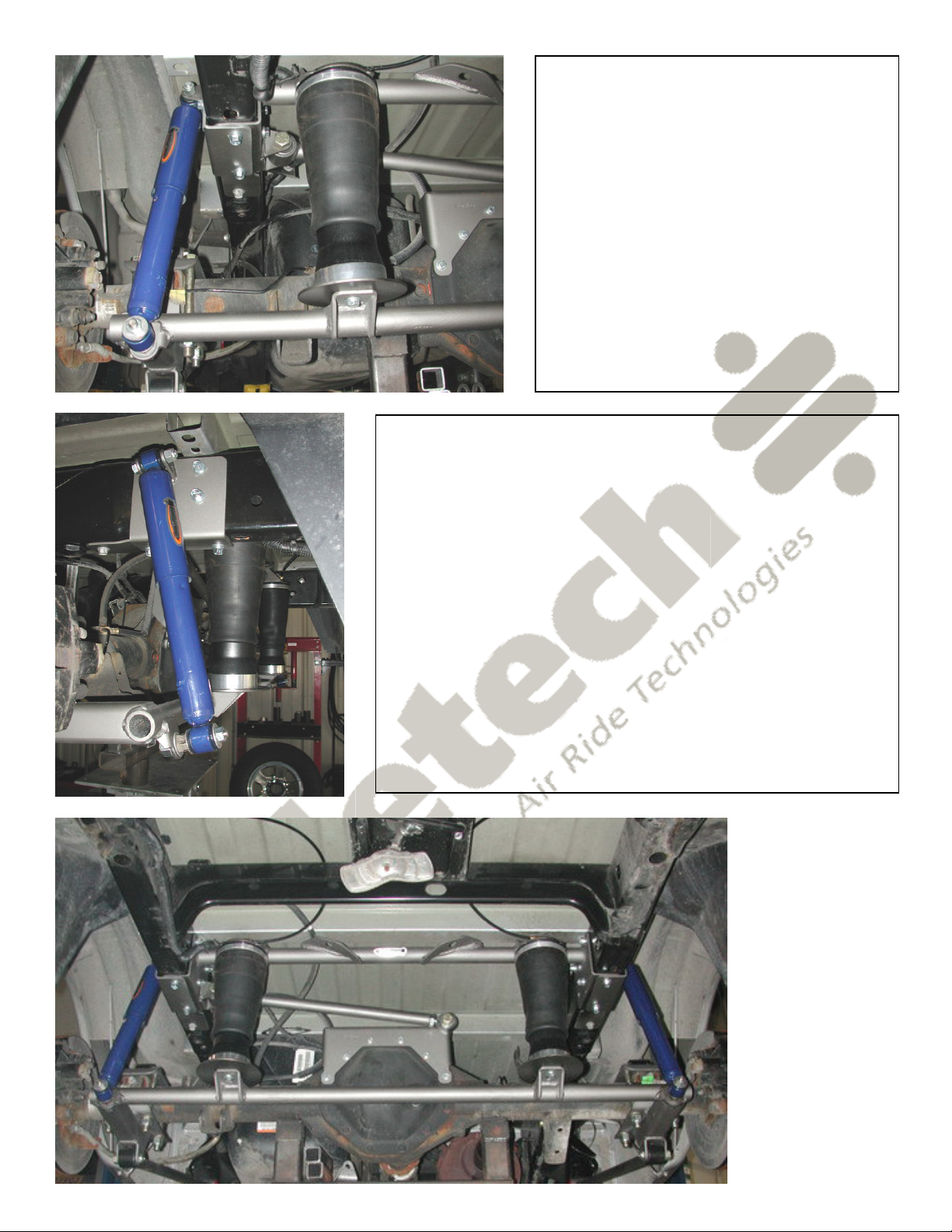
9. Thread the air fitting into the top of
the air spring, using a thread sealant.
10. Fasten the air spring to the upper
and lower bridges; use the 3/8” x 1” bolts
and snug. Be careful not to over tighten
these bolts, it will damage the air spring.
Make sure the air spring does not rub
the brake line.
Note: The air spring in the picture is
different that the one you will be
installing.
11. Remove the rear two bridge bolts from the bottom of the
frame. Install the upper shock mount to the outside of the
frame. Note there is a passenger and drivers side bracket.
Drill the remaining 4 holes with a 5/16” drill bit, and tread in
3/8” x 1” self-tapping bolts.
12. Insert shock stud through lower bridge and tighten.
Install the shock using 1/2” x 2-1/2” bolt on top and then
slide over stud on bottom with a washer on both sides of
shock. Apply a small amount of anti-seize on stud threads.
13. The final step is to check all clearances through full
suspension travel. Check all brake, fuel, air, and vent lines.
Make sure nothing can rub the air spring. At ride height the
air spring should be approx. 10.5” tall.
 Loading...