


350 S. St. Charles St. Jasper, In. 47546
Ph. 812.482.2932 Fax 812.634.6632
www.ridetech.com
Part # 11441499
88-00 C3500 Front Lower StrongArms
For Use with CoolRide
Components:
1 90000394 Driver side lower control arm
1 90000395 Passenger side lower control arm
2 90000897 Ball joints
8 90001085 Poly bushing halves
2 90000198 3” Inner sleeves
2 90000199 3.5” Inner Sleeves
2 90001082 Short bump stop

88-2000 C3500 GM 1 ton [round fender body style]
Front CoolRide system
This is the complete CoolRide system
for one side of the truck. It includes the
lower control arm, upper airspring
mount, airspring, shock absorber,
upper shock mount, bumpstop, and all
fasteners.
1. Raise vehicle to a safe, comfortable working level. Support truck with jackstands with the front
suspension hanging freely.
2. Remove coilspring. Refer to factory service manual for proper and SAFE procedure.
3. Remove lower control arm.
4. It is recommended that a dropped spindle also be installed to achieve maximum drop. We have
worked with the Belltech spindles in the past with excellent results. Follow their recommended
installation procedures.

upper mount.
5. Install the new tubular lower control arm. This new
arm provides mounting locations for the airspring, shock
absorber, bumpstop, and OEM swaybar. Install the
bumpstop in the threaded hole provided in the control
arm tube.
6. Install the airline
fitting into the airspring
then bolt the upper cup
to the top of the
airspring. Install the
threaded rod that will
hold the upper airspring
cup into the coilspring
pocket.
7. Insert the airline
through the top of the
coilspring pocket and
connect to the airspring.
Install the assembly into
the coilspring pocket
with the threaded rod
going into the oem
shock hole. Use the
provided washers and
nylock nut to secure this
8. Swing the lower control arm up
into position and attach the
balljoint and swaybar. [Install
swaybar bolt with the head down
for best ground clearance]. Attach
the airspring to the lower control
arm with the provided bolts.
Examine the assembly to ensure
the airspring will NOT contact
ANYTHING during the entire
suspension travel.
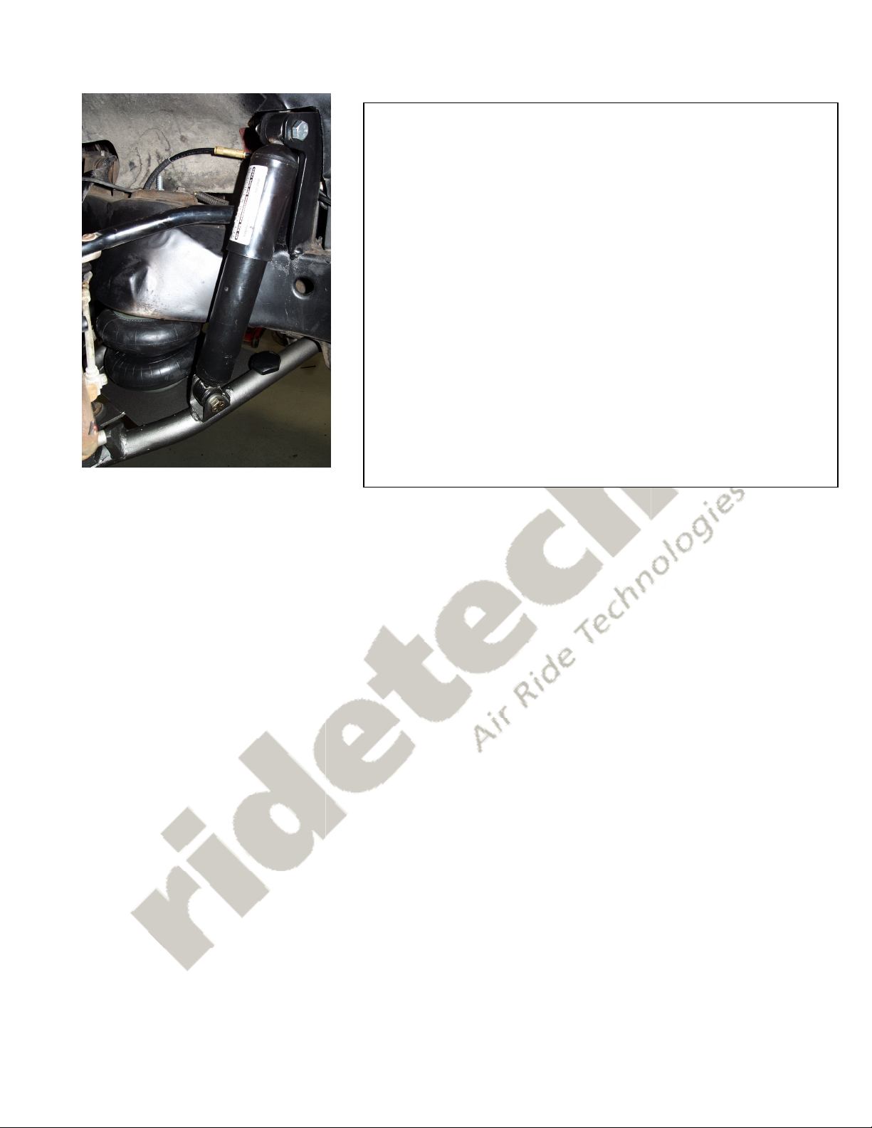
9. Attach shock absorber to the lower control arm mount.
10. Attach the upper shock tower to the shock.
11. With the lower control arm at ride height [level], and the
shock absorber at 13” eye to eye, swivel the shock/mount
assembly into position to precisely locate the upper shock
tower on the framerail. The inner fender may require
trimming for clearance. It is acceptable to trim the upper
shock tower for proper height and fitment. The end result
should place the shock so there is ½” of shock travel left
when the suspension is fully compressed. Be sure to leave
clearance for upper control arm movement during
suspension travel. Tack the tower into place and re-check
to ensure the shock won’t bottom out when the suspension
is fully compressed [deflated]. When the final location is
determined, weld upper tower into place.
 Loading...