


350 S. St. Charles St. Jasper, In. 47546
Ph. 812.482.2932 Fax 812.634.6632
www.ridetech.com
11329100 78-88 GM “G” Body
Front MuscleBar
Components:
1 90001825 Front sway bar (37.125”)
1 90001821 Driver side arm
1 90001822 Passenger side arm
2 90001819 Frame plate
2 90001820 Frame bracket
2 90000926 10 mm 90 degree PosiLink
2 90000924 10 mm Straight PosiLink
2 90001823 PosiLink Spacer (2.5”)
4 90000717 T-bushing (PosiLink to lower arm)
2 90001099 Polyurethane frame bushing
2 99250001 ¼” - 28 straight grease zerk
1 90001092 Tube of Lithium grease
2 99115009 10mm x 1.5 x 90mm stud (use Loctite) In PosiLink
Hardware Kit: 99010049
2 99111001 10 x 1.5 x 30mm Flat head Allen bolt Frame plate to frame
2 99111002 10 x 1.5 x 30mm bolt Frame bracket
4 99373003 3/8” SAE flat washer Frame bracket
4 99373005 3/8” lock washer Frame bracket
2 99373007 3/8” x 1” Self-tapping screws Frame bracket
6 99371017 3/8” x 1” Button head Allen bolt Sway bar arm to bar
6 99373003 3/8” SAE flat washer Sway bar arm to bar
6 99373005 3/8” lock washer Sway bar arm to bar
4 99112002 10mm Nylok nut PosiLink
4 99373003 3/8” flat washers PosiLink
PDF created with pdfFactory trial version www.pdffactory.com

11329100 Installation Instructions
1. This sway bar was designed for use with our lower StrongArms. Installation with other control
arms may require modification.
2. Remove the end links from the factory sway bar. Then remove the bolts attaching the sway bar to
the frame.
3. Bolt the frame plate to the frame
using the factory sway bar holes.
The front hole will use a 10mm x
30mm flat head Allen screw. The
rear hole will use a standard 10mm x
30mm hex bolt.
4. Using the bracket as a guide, drill
the front hole with a 5/16” bit. Then
thread in 3/8” self-tapping screw.
5. Slide the poly bushing over the
bar and lubricate with the lithium
grease supplied.
6. Slide the bracket over the bushing
and fasten the bar to the frame using
the 10mm x 30mm hex bolt and 3/8”
self-tapping screw.
Note: Future lubrication should only
be done with non-petroleum based
lubricants.
PDF created with pdfFactory trial version www.pdffactory.com
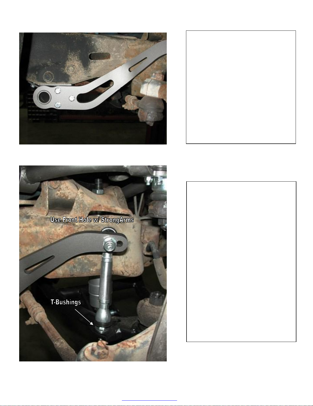
7. Bolt the sway bar arm to the bar
using 3/8” x 1” Button head screws
with flat washers and lock washers.
8. Fasten the 90 degree end of the
PosiLink to the sway bar arm using a
10mm Nylok nut and flat washers
Note: There are two holes in the
sway bar arm. For Shockwave and
CoolRide arms use the front hole.
For coils spring arms use the rear
hole.
9. Two T-bushing will be used on
each side to attach the straight end
of the PosLink to the lower control
arm. Secure with a 10mm Nylok
nut.
10. Check PosiLink alignment
through full suspension travel to
ensure that it does not bind.
PDF created with pdfFactory trial version www.pdffactory.com
 Loading...