

Page 1

350 S. St. Charles St. Jasper, In. 47546
Ph. 812.482.2932 Fax 812.634.6632
www.ridetech.com
Part # 11169100
67-69 GM “F” Body & 68-74 GM “X” Body Front MuscleBar
w/ PosiLinks
Components:
1 90000116 Sway bar
1 90000121 Driver side arm
1 90000122 Passenger side arm
2 90000137 Frame bracket
2 90001099 Polyurethane frame bushing
2 90000924 10mm straight PosiLink
2 90000926 10mm 90 degree PosiLink
4 90000717 T-bushings
2 99250001 Grease Zerk fittings – ¼”-20
2 90001092 Tube of lithium grease
2 99115001 10 x 1.5 x 36mm stud In PosiLinks (use Loc-tite)
Hardware Kit: 99010044
4 99112002 10mm Nylok nut PosiLinks
2 99373003 3/8” SAE flat washer PosiLinks
4 99311009 5/16” x 1” USS SHCS Frame bracket
4 99312003 5/16” USS Nylok nut Frame bracket
8 99313002 5/16” SAE flat washer Frame bracket
6 99371021 3/8”-16 x 1” FHSCS Arm to sway bar (Use Loc-tite)
2 99502003 ½” SAE Nylok jam nut Steering arm
Page 2
1. This sway bar is designed for use with our lower StrongArms. Installation on other arms
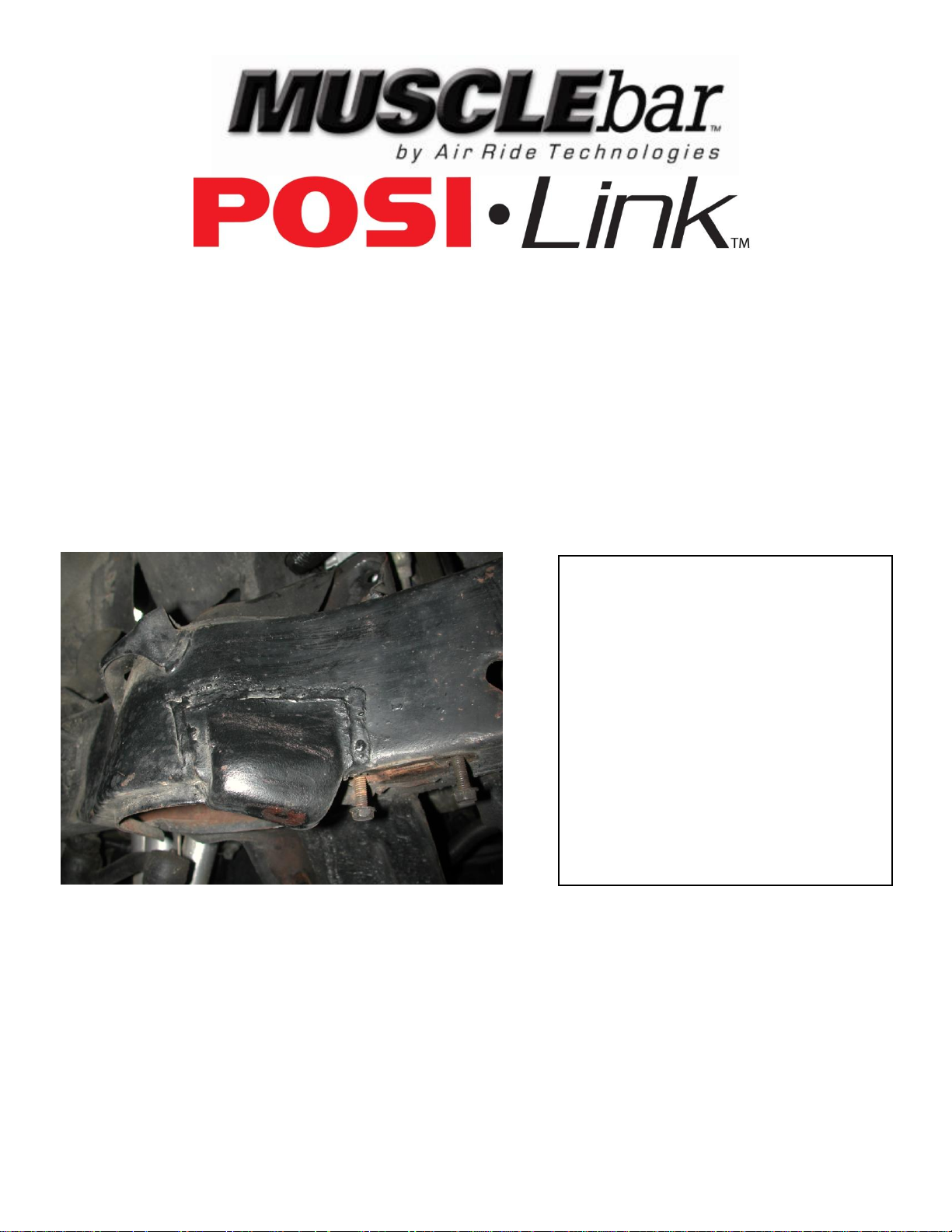
3. On some cars, the compression
stop bracket that is welded to the
frame will need to be removed to
allow clearance for the sway bar arm.
may require modification.
2. Remove the end links from the factory sway bar. Then remove the bolts attaching the sway
bar to the frame.
3. On some cars, the compression stop bracket that is welded to the frame will need to be removed
to allow clearance for the sway bar arm.
11169100 Installation Instructions
Page 3
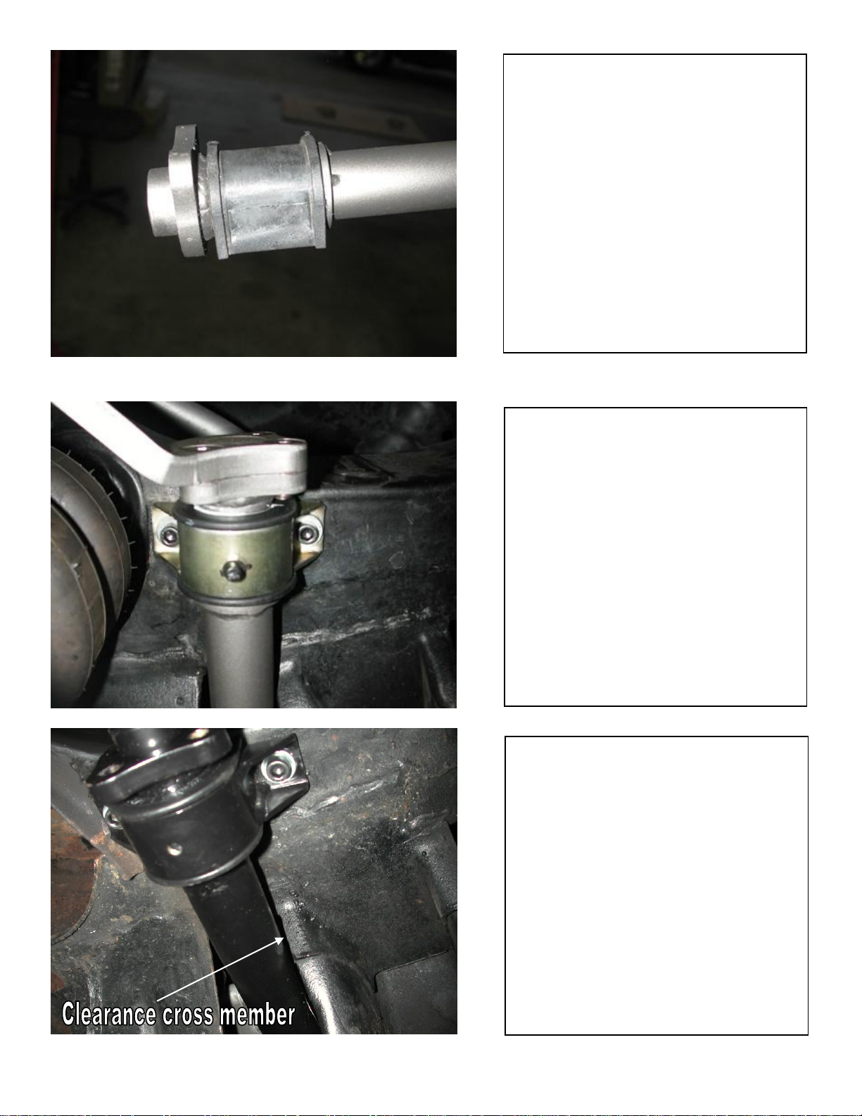
4. Apply lithium grease to the poly
bushing then slide it over the sway
bar.
5. Secure the sway bar to the frame
with two 5/16” x 1” Socket Head Cap
Screws, flat washers and Nylok nuts.
Note: Due to the larger diameter
bar, the front hole must be drilled
with a 5/16 bit, in front of the factory
hole. Use the bracket as a template.
6. On some cars clearance of the
cross member may be needed for
sway bar clearance.
.
Page 4
9. Attach the other end of the
PosiLink to the sway bar arm with a
3/8” flat washer and a 10mm Nylok
nut.
10. Check sway bar and PosiLink
clearance through full suspension
travel, turning the wheel lock to lock.
Make sure that the PosiLinks do not
bind.
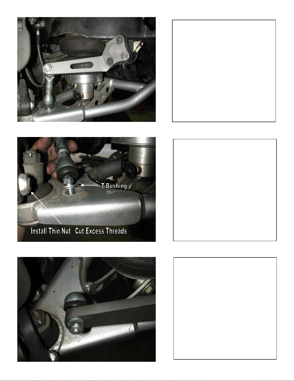
7. Attach the arm to the bar using
three 3/8” x 1” Flat Head Cap
Screws. Blue or Green Loc-tite
must be applied to the threads of
these bolts.
8. The straight end of the PosiLink
will attach to the lower control arm.
A “T”-Bushing must be installed
on each side of the control arm.
Secure the assembly with a 10mm
Nylok nut.
Note: To avoid the front steering
arm bolt hitting the PosiLink, a thin
Nylok jam nut is installed and the
excess threads must be cut off.
 Loading...