


1 -
1
I. INTRODUCTION
FIGURE 1
-
2: STEPWEL
L MODEL
FIGURE 1
-
1: DEDICAT
ED ENTRY MODEL
Safe and easy access to mass-transit vehicles is provided by the RICON Mirage F9T Transit Use
Wheelchair and Standee Lift. Refer to Figures 1-1 and 1-2. This manual covers both Dedicated
Entry and Stepwell models. The Dedicated Entry model is intended for installation in a vehicle
baggage bay, or similar location. The Stepwell model is installed within a vehicle stepwell.
An electric-motor driven hydraulic pump assures smooth platform movement, with a maximum
capacity of 660 pounds (300 kilograms). It is operated by a trained attendant or the vehicle
operator. The operator uses control switches to withdraw the platform from the vehicle (deploy)
and lower it to ground level. The passenger boards the large non-skid platform and is then is
raised to floor height. The passenger enters the vehicle, the operator lowers the platform and
retracts it back into the vehicle (stow). When the passenger exits, the operator uses control
switches to withdraw the platform from the vehicle (deploy) and raise it to floor height. The
passenger boards the platform and is then lowered to the ground by the operator. The
passenger departs, and the operator returns the platform to the stow position.
One individual can manually operate the
lift when normal power is not present.
A manual release mechanism is provided to ease the task of pulling the
platform out of its enclosure by hand.
The hydraulic pump assembly includes
a manually operated back-up pump to
raise the platform, and a release valve
to lower it. The front platform rollstop,
normally power operated, has a manual
override knob for back-up use.
This manual contains complete operating
instructions for each lift, and a brief maintenance chapter. It is important to passenger safety that the lift operator be familiar
with the Operating Instructions chapter. It
is also important to properly maintain the
lift by following the recommended cleaning,
lubrication, and inspection directions in the
Maintenance chapter.
Please contact Ricon Product Support if you have questions about this manual, or need additional copies:
Ricon Corporation
7900 Nelson Road
Panorama City, CA 91402...................................................................... (818) 267-3000
Outside (818) Area Code......................................................................... (800) 322-2884
World Wide Website......................................................................... www.riconcorp.com
Littlemoss Business Park, Littlemoss Road
Droylsden, Manchester
United Kingdom, M43 7EF............................................................... (+44) 161 301 6000
32DF9T01.A

1 -
2
A. LIMITED WARRANTY
RICON CORPORATION
~ ONE-YEAR LIMITED WARRANTY ~
Ricon Corporation (Ricon) warrants to the original purchaser of this product that Ricon will repair or
replace, at its option, any parts that fail because of defective material or workmanship as follows:
• Repair or replace parts for a period of one year from the date of purchase. A complete list of parts
covered by this warranty can be obtained from an authorized Ricon service technician.
• Labor costs for specified parts replaced under this warranty for a period of one year from date put
into service. A Ricon rate schedule determines parts covered and labor allowed.
If You Need to Return a Product: Return this Ricon product to Ricon Corporation, following the Ricon
RMA procedure. Please give as much advance notice as possible and allow a reasonable amount of
time for repair.
If You are Traveling: All authorized Ricon service technicians will honor this warranty. Consult a tele-
phone directory, or call Ricon Product Support, for the name of the nearest authorized Ricon service
technician. You may also locate a technician at our website, www.riconcorp.com. Click on “Ricon
Corporation” on the home page.
This Warranty Does Not Cover:
• Malfunction or damage to product parts caused by accident, misuse, lack of proper maintenance,
neglect, improper adjustment, modification, alteration, the mechanical condition of the vehicle, road
hazards, overloading, failure to follow operating instructions, or acts of Nature (i.e., weather, lightning, flood, etc.).
NOTE: Ricon recommends this product be inspected by an authorized Ricon service technician at
least once every six months, or sooner if necessary. Any required maintenance or repair
should be performed at that time.
WARNING!
THIS PRODUCT HAS BEEN DESIGNED AND MANUFACTURED TO EXACT SPECIFICATIONS.
- ANY MODIFICATION OF THIS PRODUCT CAN BE DANGEROUS -
This Warranty is Void If:
• The product has been installed or maintained by someone other than an authorized Ricon service
technician.
• The product has been modified or altered in any respect from its original design without written
authorization by Ricon.
Ricon disclaims liability for any personal injury or property damage that results from operation of a
Ricon product that has been modified from the original Ricon design. No person or company is authorized to change the design of this Ricon product without written authorization by Ricon.
Ricon's obligation under this warranty is exclusively limited to the repair or exchange of parts that
fail within the applicable warranty period.
Ricon assumes no responsibility for expenses or damages, including incidental or consequential
damages. Some states do not allow the exclusion or limitation of incidental or consequential damages, so the above limitation or exclusion may not apply.
Important: The warranty registration card must be completed and returned to Ricon within twentydays after installation of this Ricon product for the warranty to be valid. The warranty is not transferable.
The warranty gives specific legal rights. There may be other rights that vary in each state.
32DF9T01.A

1 -
3
B. SHIPMENT INFORMATION
Ricon does not sell directly to the user because of the specialized nature of the product.
The product is distributed through a worldwide network of authorized Ricon service
technicians, who accomplish sales and installation.
Be sure the lift installation kit, if supplied, contains all the items listed on the kit packing
list. Please report any missing items immediately to Ricon Product Support. The
warranty and owner registration cards must be completed and returned to Ricon within
20 days to validate warranty.
NOTE: Sales/Service Personnel must review the Warranty and this Operator Manual with the
user to be certain that they understand safe operation of the product. Instruct the user
to follow the operating instructions without exception.
C. GENERAL SAFETY PRECAUTIONS
The following general safety precautions must be followed during installation, operation,
service, and maintenance:
§ Do not attempt maintenance, repairs, or adjustments without the presence of a
person capable of rendering aid.
§ Attend all injuries, regardless of how slight. Administer first aid or seek medical
attention immediately.
§ Wear protective eye shields and appropriate clothing at all times.
§ Exercise caution when operating lift to avoid injury. Be certain that hands, feet,
legs and clothing are not in path of the platform as it moves.
§ Be cautious when using metallic (conductive) tools near the battery.
§ Check under vehicle before drilling or cutting to avoid damage to the frame, sub-
frame members, wiring, hydraulic lines, etc.
§ Thoroughly understand the operating instructions before attempting to operate lift.
§ Inspect lift before each use. Do not operate lift if an unsafe condition is present,
or if there are unusual noises or movements.
§ Keep others clear during lift operation.
§ Maintain the lift at its highest level of performance by doing the required mainte-
nance. Ricon recommends a thorough inspection every six months.
32DF9T01.A
1 -
4
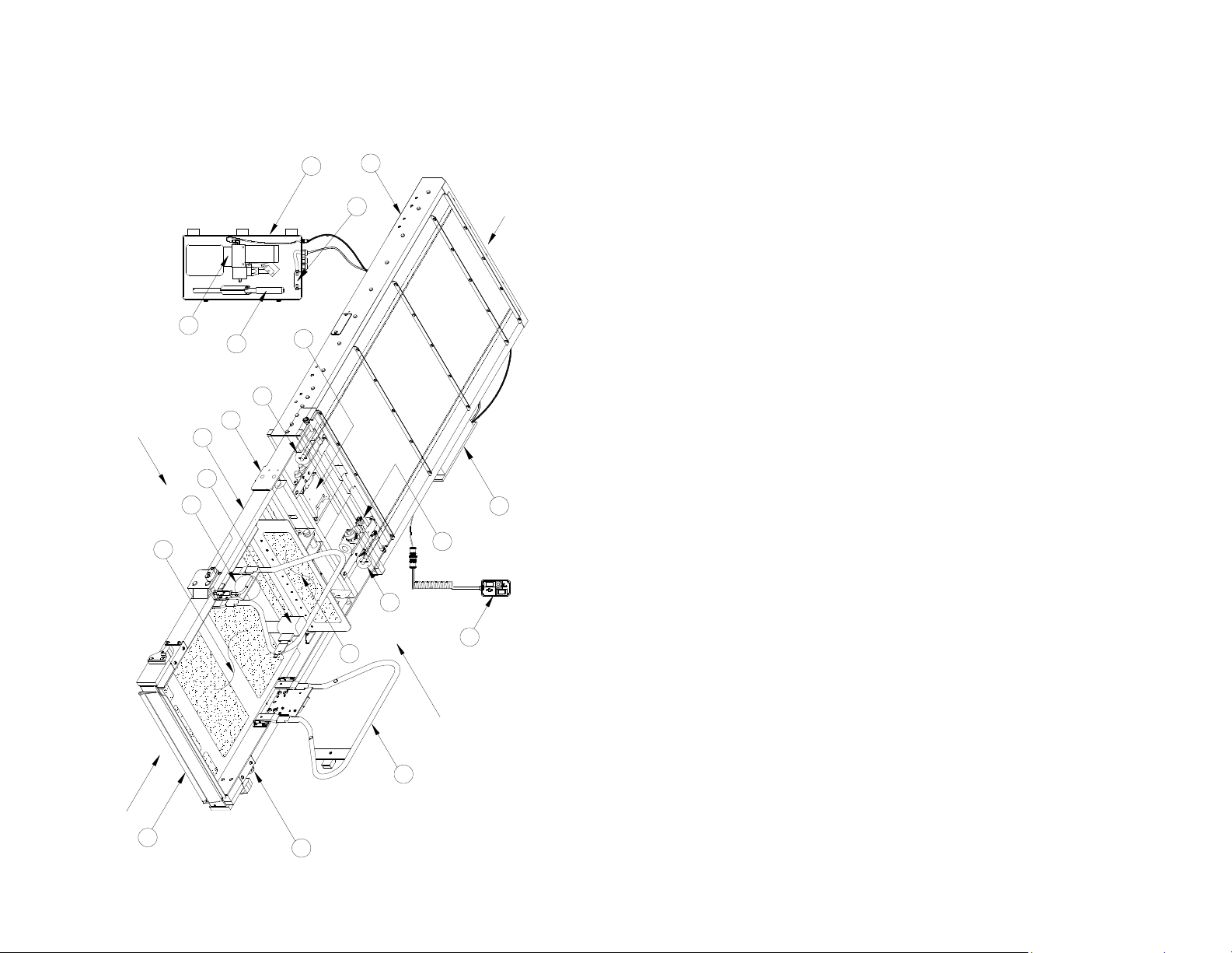
D. MAJOR LIFT COMPONENTS
FIGURE 1
-
3: LIFT CO
MPONENTS
FOR DEDICATED ENTRY
MODEL
1. DEDICATED ENTRY MODEL
Major components of the Mirage F9T Transit Use Dedicated Entry Wheelchair and
Standee Lift are in Figure 1-3. A description of each component is in Table 1-1.
LEFT
14
3
10
11
15
1
18
REAR
2
4
19
9
7
5
8
9
FRONT
13
12
32DF9T01.A
17
6
RIGHT
16

1 -
5
TABLE 1-1: LIFT COMPONENTS FOR DEDICATED ENTRY MODEL
REF
Left, Right, Front, Rear Reference points from outside vehicle looking inward at lift.
1 Pump Enclosure Contains lift electrical and hydraulic control components.
2
3
4 Pump Handle Used to manually operate hydraulic pump.
5 Pull Box
6 Control Pendant Hand-held device used to control lift operation.
7 Carriage
8
9
10
11 Lifting Frame
12
13 Platform Rollstop
14 Platform Curbed area occupied by passenger during lift operations.
15
16 Standee Handrails Provides platform occupant with a stable handhold.
17 Bridgeplate
18 Enclosure Platform housing is rigidly attached to vehicle chassis.
19 Controller
NAME DESCRIPTION
Electric Circuit
Breakers
Hydraulic Pump
Assy.
Deployment System
Manual Platform
Release Shafts 2ea
Slam-Lock
Handle
Manual Rollstop
Override Knob
Occupant Safety
Belt
Prevents high-current damage to lift electrical components.
Electro-hydraulic unit provides hydraulic pressure used to raise
platform.
Houses electrical termination points to lift, and a hydraulic line
disconnect point.
Part of traveling frame that is mounted on rollers; moves on
rails located inside enclosure. Supports lifting frame.
Part of carriage. Employs an electric gear-motor to propel platform out of enclosure, or pull it back in.
Used when electric power is not available to lift. Releases platform from enclosure to facilitate manual deployment. Actuated
by engaging and rotating either indicated shaft.
Locks handrail in upright position. L-handle unlocks handrail
from upright position before lowering.
Hinged arms that lift or lower platform; driven by single hydraulic cylinder attached to carriage.
Provides manual control of rollstop if electrical power is lost.
Front barrier prevents wheelchair from inadvertently rolling off
the platform during lift use.
Safety belt helps prevent unintentional acceleration of wheelchair from platform. Electrically interlocked so that “UP” and
“DOWN” functions are disabled if the belt is unbuckled.
Plate unfolds when platform is at floor height to bridge gap between platform and vehicle interior.
Translates pendant commands to signals that control lift electrical and hydraulic components.
END OF TABLE
32DF9T01.A
1 -
6
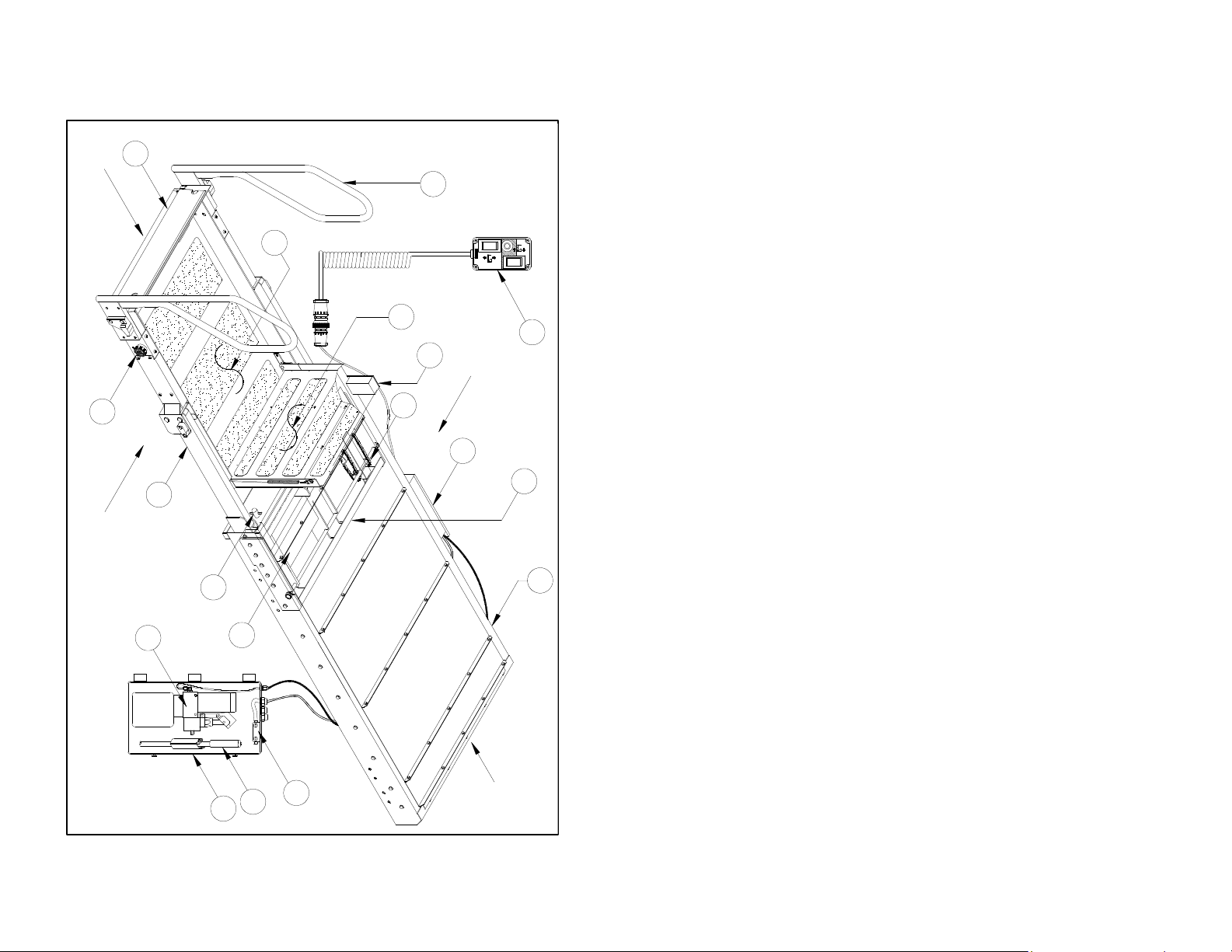
2. STEPWELL MODEL
FIGURE 1
-
4: LIFT CO
MPONENTS FOR STEPWEL
L MODEL
Major components of the Mirage F9T Transit Use Stepwell Model Wheelchair and
Standee Lift are in Figure 1-4. A description of each component is in Table 1-2.
FRONT
12
14
13
15
LEFT
16
6
11
RIGHT
8
5
10
9
4
18
7
17
REAR
3
2
1
32DF9T01.A

1 -
7
REF
TABLE OF CONTENTS
NEXT CHAPTER
TABLE 1-2: LIFT COMPONENTS FOR STEPWELL MODEL
NAME DESCRIPTION
Left, Right, Front, Rear
1 Pump enclosure
2 Pump Handle Handle used to manually operate hydraulic pump.
3 Electric Circuit
Breakers
4 Hydraulic Pump
Assy.
5 Pull Box Houses electrical termination points to lift, and a hydraulic line
6 Control Pendant Hand-held device used to control lift operation.
7 Carriage Part of traveling frame that is mounted on rollers; moves on
8 Deployment System Part of carriage. Employs an electric gear-motor to propel plat-
9 Manual Platform Re-
lease Shafts - 2ea
10 Lifting Frame Hinged arms that lift or lower platform; driven by single hydrau-
11 Manual Rollstop
Override Knob
12 Platform Rollstop Front barrier prevents wheelchair from inadvertently rolling off
13 Platform Curbed area occupied by passenger during lift operations.
14 Standee Handrails Provides platform occupant with a stable handhold.
15 Bridgeplate Plate unfolds when platform is at floor height to bridge gap be-
16 Sto-Loc Safety lock retains platform when in stowed position (re-
17 Enclosure Platform housing is rigidly attached to vehicle chassis.
18 Controller Translates pendant commands to signals that control lift elec-
Reference points from outside of vehicle looking inward at installed lift.
Contains lift electrical and hydraulic control components.
Prevents high-current damage to lift electrical components.
Electro-hydraulic unit provides hydraulic pressure needed to
raise platform.
disconnect point.
rails located inside enclosure. Supports lifting frame.
form out of enclosure, or pull it back in.
Used when lift electric power is lost. Releases platform from
enclosure to facilitate manual deployment. Actuated by engaging and rotating either indicated shaft.
lic cylinder attached to carriage.
Provides manual control of rollstop if electrical power is lost.
the platform during lift use.
tween platform and vehicle interior.
tracted); releases automatically when OUT button is pressed.
trical and hydraulic components.
END OF TABLE
32DF9T01.A
 Loading...