

Page 1

SORTER STAPLER
TS20A, TS20B
(C560, C561)
Page 2

SECTION 1
OVERALL MACHINE
INFORMATION
Page 3
15 November 1995 SPECIFICATIONS
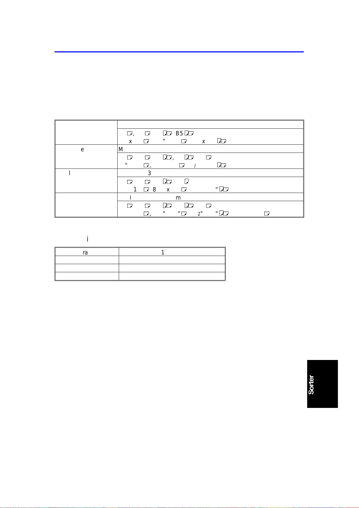
1. SPECIFICATIONS
Configuration : Console (up to 2 units can be inst alled; one each
of TS20A and TS20B)
Number of Bins: 20 bins per sorter + proof tray
Paper Size:
Proof tray Maximum: 320 x 447 mm, 12.6" x 17.6"
M
, B4 M, A4 LM, B5
A3
11" x 17" M, 81/2" x 14" M, 81/2 x 11"
Sort mode Maximum: 300 x 432 mm, 11.9" x 17.1"
M
, B4 M, A4 LM, B5 LM, A5
A3
11" x 17" M, 81/2 x 14" M, 81/2" x 11"
Staple mode Maximum: 300 x 432 mm, 11.9" x 17.1"
M
, B4 M, A4 LM, B5
A3
11" x 17" M, 81/2" x 14" M, 81/2" x 11"
Class mode Maximum: 300 x 432 mm, 11.9" x 17.1"
M
, B4 M, A4 LM, B5 LM, A5
A3
11" x 17" M, 81/2" x 14" M, 81/2" x 11" LM, 51/2" x 81/2"
LM
LM
M
LM
L
LM
M
M
Paper Weight:
Non-sort tray 47 ~ 210 g/m2, 12.6 ~ 55.8 lb
Sort mode 64 ~ 82 g/m
Staple mode 64 ~ 82 g/m
Class sort mode 64 ~ 82 g/m
2
, 17.1 ~ 21.8 lb
2
, 17.1 ~ 21.8 lb
2
, 17.1 ~ 21.8 lb
Printing Speed: Non-sort tray: 60 ~ 120 cpm
Sort, Staple, or Class sort mode: 60 cpm
Proof Tray Capacity: 300 sheets
(Less than 64 g/m2, 17.0 lb)
200 sheets
(Less than 157 g/m2, 41.7 lb)
150 sheets
(Less than 210 g/m2, 558 lb)
1-1
Page 4
SPECIFICATIONS 15 November 1995
Bin Capacity: Sorting
50 sheets
(64 ~ 82 g/m2, 17.1 ~ 21.8 lb, smaller than B4,
81/2" x 14")
25 sheets
(64 ~ 82 g/m2, 17.1 ~ 21.8 lb, smaller than A3,
11" x 17" and paper sizes other than those
mentioned under "P ap er size" )
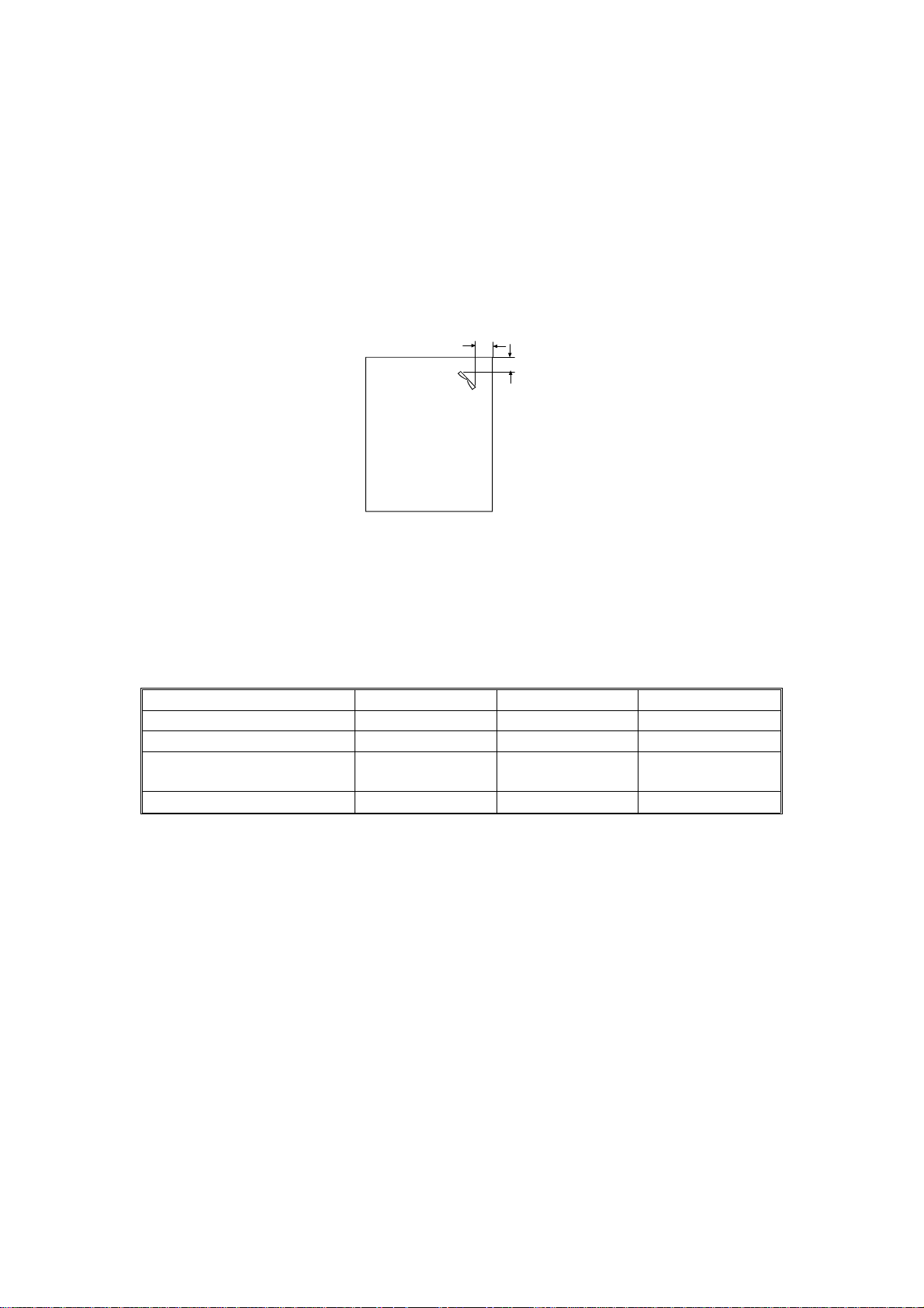
Stapling Position:
a = 5 ± 2.5 mm, 0.2" ± 0.1"
b = 5 ± 2.5 mm, 0.2" ± 0.1"
C560V500.wmf
Stapler Capacity: 50 sheets (64 g/m2, 17.1 lb)
40 sheets (80 g/m2, 21.3 lb)
42 sheets (75 g/m2, 20 lb)
Staple Replenishmen t: Cartridge exchange (5,00 0 staples/cartridge)
Dimension (sorter stapler o nly):
Width Depth Height
One sorter stapler: bins down 908 mm, 35.8" 597 mm, 23.6" 926 mm, 36.5"
One sorter stapler: bins up 908 mm, 35,8" 597 mm, 23.6" 1,082 mm, 42.6"
Two sorter staplers: bins
down
Two sorter staplers: bins up 1,507 mm, 59.4" 617 mm, 24.3" 1,082 mm, 42.6"
1,507 mm, 59.4" 617 mm, 24.3" 926 mm, 36.5"
Weight: 57.5 kg, 127 lb (One sorter stapler)
106.5 kg, 235 lb (Two sorter staplers)
Power Source: AC 120 V 50/60Hz
AC 220 ~ 240 V, 50/60 Hz, 1.6A
(1st Sorter Staple r )
DC 24 V
(2nd Sorter Stapler, from th e 1st Sort er St ap ler)
Power Consumption: One sorter: 140 W; Two sorters: 160 W
Noise Emission: Less than 70 dB(A): the measureme nt s are to be
made in accordance with ISO7779.
1-2
Page 5
C
15 November 1995 MECHANICAL COMPONENT LAYOUT
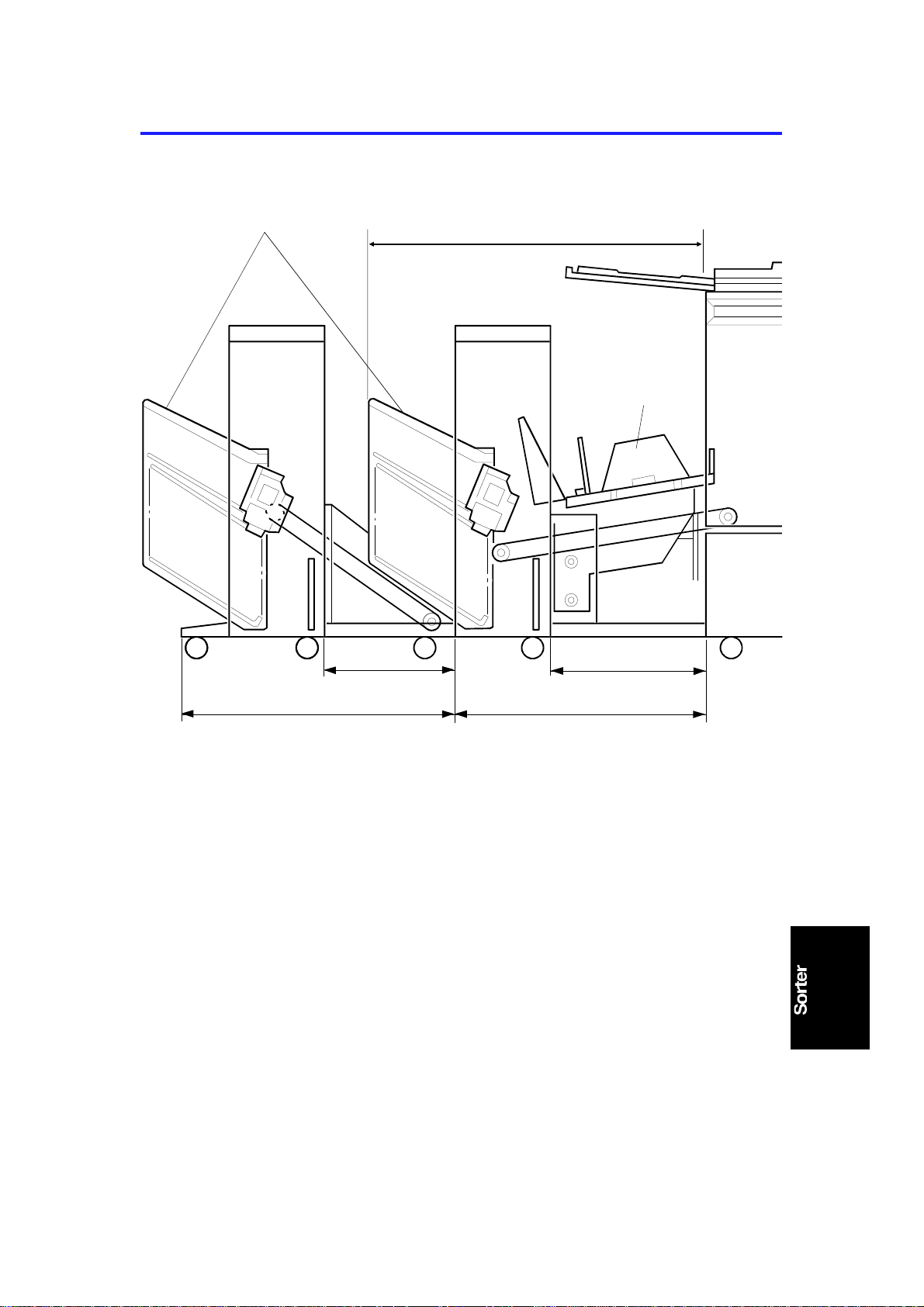
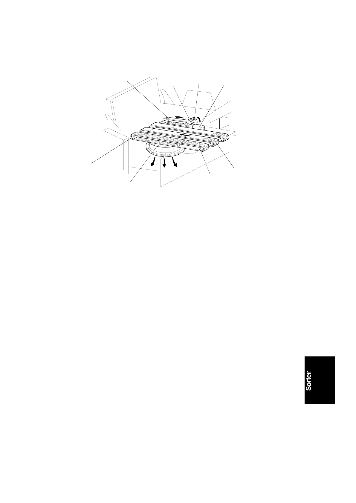
2. MECHANICAL COMPONENT LAYOUT
F
A
E
B
A: 1st Sorter
B: 2nd Sorter
C: 1st Transport Unit
D: 2nd Transport Unit
E: Paper Delivery Table
F: Bins
D
C560V501.wmf
1-3
Page 6
H
DRIVE LAYOUT 15 November 1995
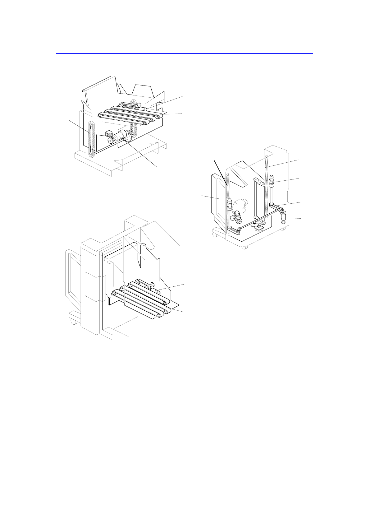
3. DRIVE LAYOUT
D
G
A
F
C560V502.wmf
E
M
H
I
L
J
K
B
C560V503.wmf
C
A: 1st Transport Unit
B: Sorter
C: 2nd Transport Unit
D: 1st Transport Motor
E: Transport Belts
F: Paper Delivery Table Motor
G: Drive Chains
E
C560V504.wmf
H: Springs
I: Helical Wheels
J: Bin Shift Belts
K: Bin Shift Motor
L: Bins
M: 2nd Transport Motor
1-4
Page 7

15 November 1995 ELECTRICAL COMPONENT DESCRIPTION
4. ELECTRICAL COMPONENT DESCRIPTION
Refer to the electrical compone nt layou t on the reverse side of the
point-to-point diagram (on waterproof paper)
Name Function Index
No.
Switch
Manual Staple Key Allows the paper stack to be stapled manually in
the top bin (manual stapling is only done in the top
bin).
Paper Stack Holding Arm Detects when the paper stack holding arm is in
the bins and cuts the dc line to the bin shift motor.
Bin Upper Limit Turns off the 24V line to the bin shift motor when
the bin unit reaches the upper limit position.
Bin Lower Limit Turns off the 24V line to the bin shift motor when
the bin unit reaches the lower limit position.
Staple Cover Open Detects when the staple cover is open and cuts
power to the stapler.
Staple Position Detects when the staple unit is at the stapling
position.
Staple Unit Movement Detects while the staple unit is moving between
the staple unit home position and the stapling
position.
Staple Safety Turns off the 24V line to the staple motor when
there is an obstacle at the stapling position.
Bin Unit Obstacle Turns off the 24V line to the paper delivery table
motor when the bin unit cannot be lowered as a
result of an obstacle.
1st Transport Upper Limit Turns off the 24V line to the paper delivery table
motor when the 1st transport unit reaches the
upper limit position.
1st Transport Cover Open Detects whether the cover is open. 33
1st Transport Safety Turns off the 24V line to the paper delivery table
motor when the paper delivery table cannot be
raised as a result of an obstacle.
Sensor
Helical Wheel H.P. Detects when the helical wheel is at the home
position.
Bin Unit H.P. Detects when the bin unit is at the home position. 5
Bin Shift Motor Rotation Monitors bin shift motor rotation by detecting the
movement of a timing disk.
Staple H.P. Detects if the staple hammer is in the home
position.
Staple End Detects staple end. 18
Paper Detects whether there are copies under the
hammer.
2nd Transport Motor Rotation Monitors and controls 2nd transport motor rotation
by detecting the movement of a timing disk.
1
2
3
8
12
13
14
19
20
32
34
4
7
17
21
22
1-5
Page 8

ELECTRICAL COMPONENT DESCRIPTION 15 November 1995
Name Function Index
No.
2nd Transport Determines the bin shift timing and detects the
paper count. This is also a jam detector.
Bin/Jam (LED) Detects if there is paper in the bins (light emitting
element). This is also a jam detector.
Bin /Jam (Photo Tr.) Detects if there is paper in the bins (light receiving
element). This is also a jam detector.
Jogger Bar H.P. Detects if the jogger bar is in the home position. 27
Trailing Edge Detects a paper jam if the paper does not exit to
the bin completely (the trailing edge is left
between the transport unit and bin.)
1st Transport Sort Mode
Position
1st Transport Non-Sort Mode
Position
1st Transport Motor Rotation Monitors and controls 1st transport motor rotation
1st Transport Determines the bin shift timing and detects the
Motor
Bin Shift Drives the helical wheel to shift the bin unit
Staple Unit Shift Moves the staple unit between the staple unit
Staple Drives the staple hammer. 16
2nd Transport Drives the transport rollers and belts. 23
2nd Transport Fan Sucks air through the holes in the transport belt to
Jogger Bar Drives the jogger bar to jog the stack of paper
1st Transport Drives the transport rollers and belts. 36
Paper Delivery Table Drives the paper delivery table up/down. 39
1st Transport Fan Sucks air through the holes in the transport belt to
PCB
DC Power Supply (1st Sorter
only)
Sorter Main Control Controls all sorter stapler functions. 11
Solenoid
Paper Stack Holding Arm Drives the paper stack holding arm to hold the
Paper Delivery Table Motor
Stop
Stops the 1st transport unit in the sort mode
position when it detects that the 1st transport unit
is in the sort mode position.
Stops the 1st transport unit in the non-sort mode
position when it detects that the 1st transport unit
is in the non-sort mode position.
by detecting the movement of a timing disk.
paper count. It also detects paper jams.
up/down.
home position and the stapling position.
hold the paper on the transport belts.
against the bin side plate (stepper motor).
hold the paper on the transport belts.
Rectifies the ac input and outputs dc voltage. 9
stack of paper in the bin.
Prevents the paper delivery table motor from
rotating under the weight of the table at the sort
mode or non-sort mode position.
25
26
30
29
31
38
35
41
6
15
24
28
37
10
40
1-6
Page 9
15 November 1995 BASIC OPERATION
5. BASIC OPERATION
5.1 N O N-S ORT MO DE
[A]
C560V506.wmf
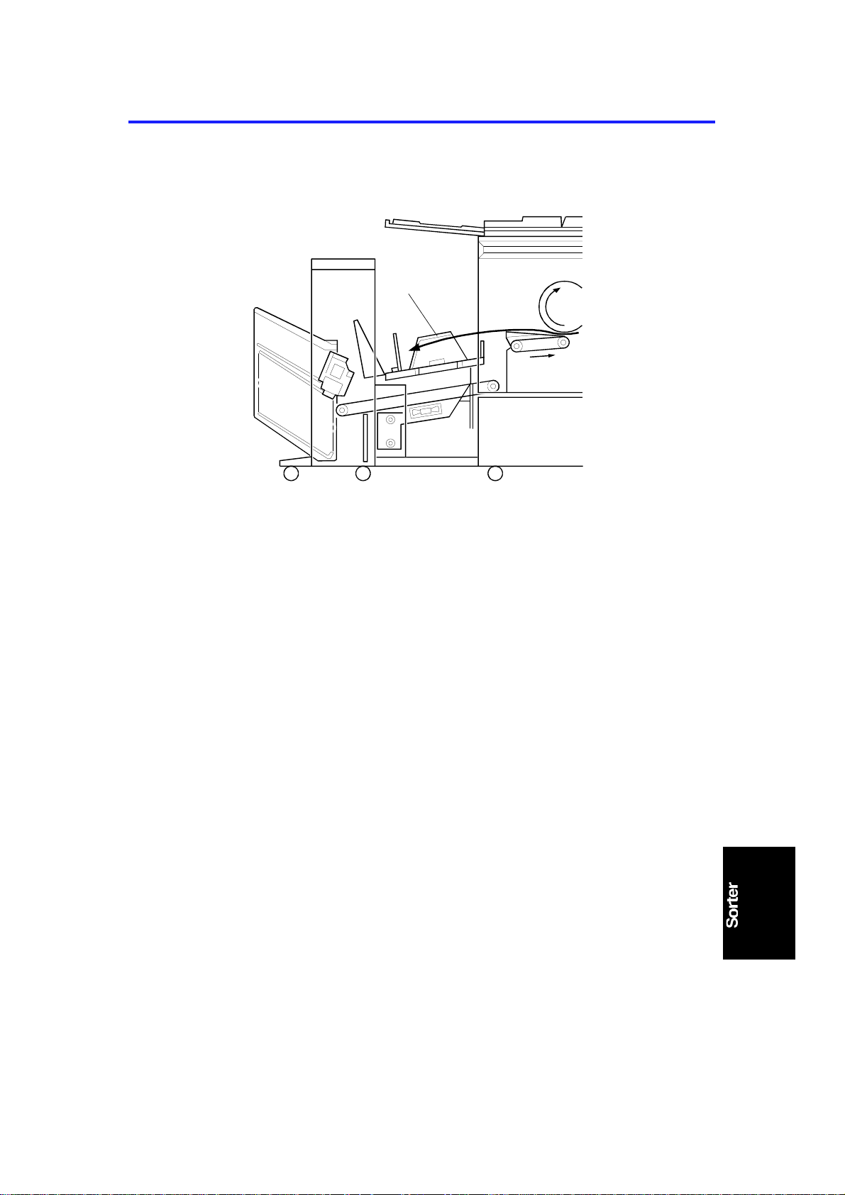
Non-sort mode copies exiting the print er enter the paper delivery table [A],
which has been lowered to th e no n-so rt mode position when this mode has
been selected.
1-7
Page 10
[C]
BASIC OPERATION 15 November 1995
5.2 SORT MODE
[A]
[B]
C560V505.wmf
[D]
C560V507.wmf
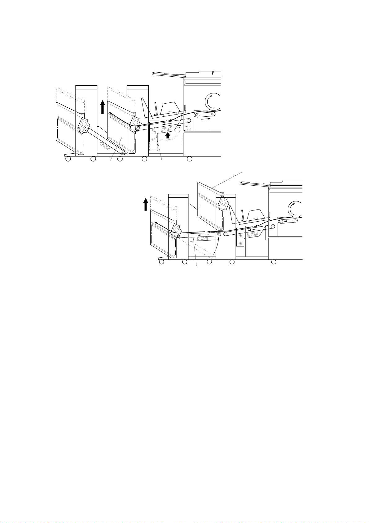
Copies exiting the printer enter the sorter. The paper delivery table has been
raised to the sort mode position when this mode has been selected. Copies
are delivered to the bins [A] throu gh the 1st tra nsp ort belt [B] in the correct
order. The copies in the bins are arranged by the jogger bar.
The 1st sorter can hold 20 sorted copies. If the 2nd sorter is in sta lled next to
the 1st sorter, an additional 20 copie s can be sorte d.
When the 20th copy has been fed to th e 1st sorter, the bin unit [C] is at its top
position and the bin unit has raised the 2nd tran sport unit [D] to its ready
position. The 21st to 40 th copies are transported to th e 2nd sorter. After the
final copy of an origina l pag e has passed the 2nd transport unit , th e 2n d
transport unit and 1st sorter bin unit and 2nd sorter bin unit are lowe red to the
initial position, an d th e machine will transport copies t o th e bin s of the 1st
sorter again.
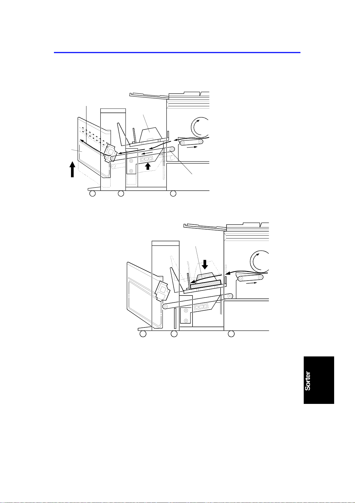
When the final set of copies has been jogged, the bins all go to home
position, then the stap le un it sta ples the copies stacked in the 1st bin. Then,
the bin unit is moved up so that the next bin is at th e stapling position. When
the final set of copie s has be en stap led , the bin unit is lowered to the home
position.
1-8
Page 11

SECTION 2
DETAILED SECTION
DESCRIPTIONS
Page 12
15 November 1995 1ST TRANSPORT UNIT
1.
1ST TRANSPORT UNIT
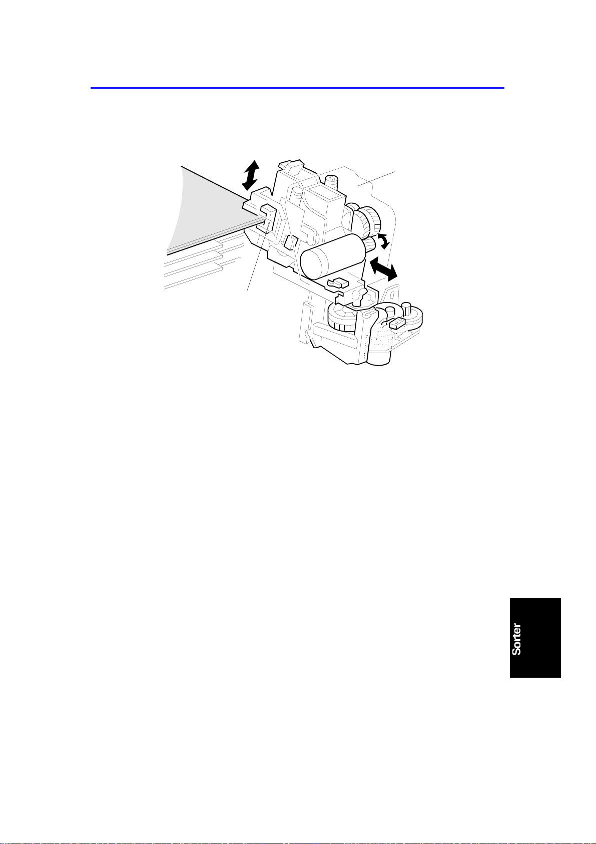
1.1 OVERVIEW
[C]
[A]
[D]
[B]
C560D500.wmf
[E]
C560D501.wmf
The 1st transport unit consists of the paper de livery ta ble [A] and paper
transport belt unit [B]. These two units shift to either the uppe r or lower
position together. The upper position is used for th e sort mode ; the paper [C]
passes through the paper transpo rt belt unit to the bin unit [D] . The lower
position is used for the non-sort mode; the paper [E] is delivered to the paper
delivery table.
2-1
Page 13
1ST TRANSPORT UNIT 15 November 1995
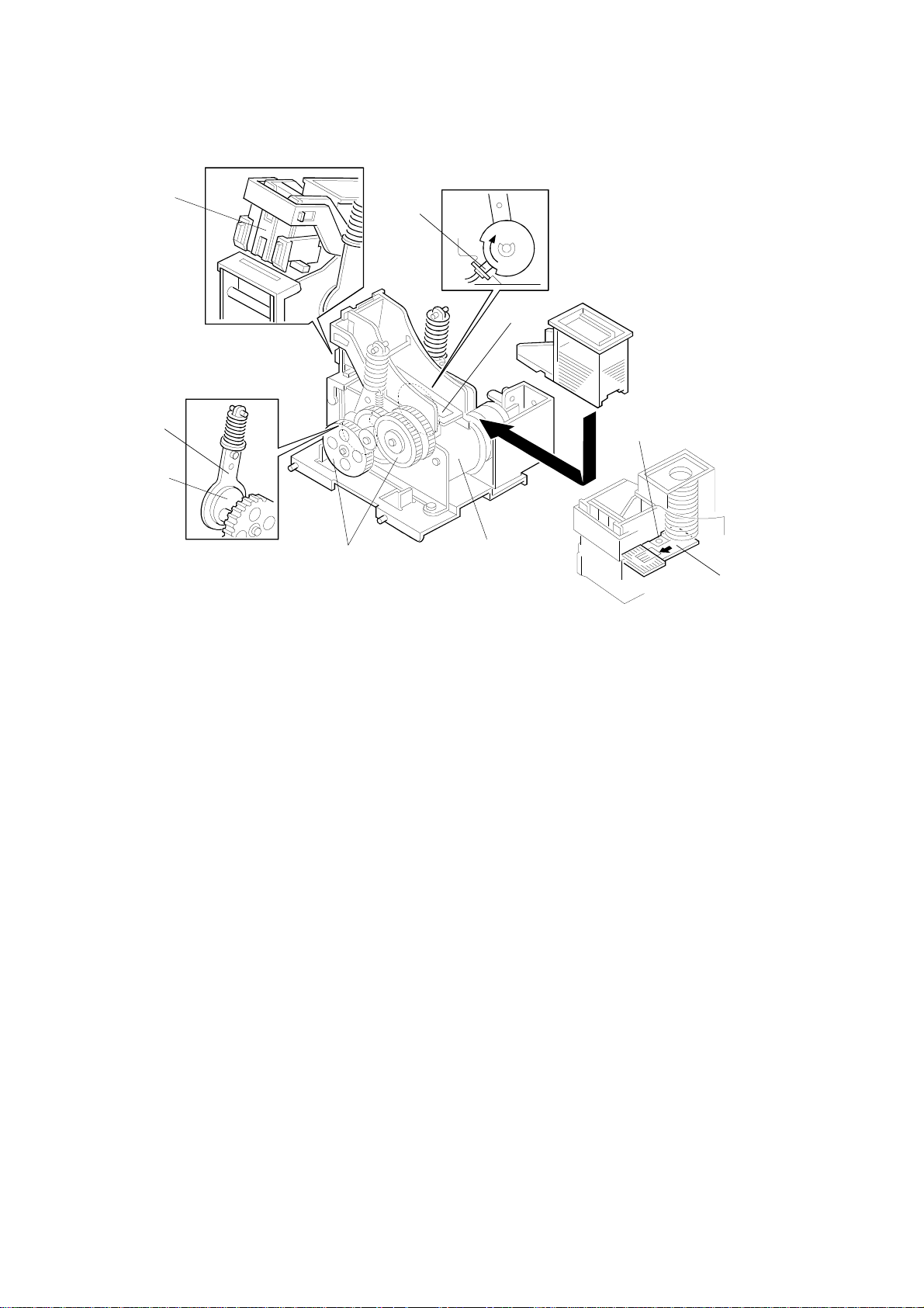
1.2 1ST TRANSPORT UNIT DRIVE MECHANISM
[C]
[B]
[A]
[F]
[H]
C560D502.wmf
[G]
[J]
[E]
[D]
[I]
C560D503.wmf
When the paper delivery table motor [A] rotates coun terclockwise, the 1st
transport unit is raised thro ug h the gears [B] and drive chains [C]. The motor
stops when the actuator [D] on the chain enters the 1st transport sort mode
position sensor [E]. The paper de livery ta ble moto r st op solenoid [F] turns
on/off at the same time as the pape r delivery table motor. When the solenoid
turns off, the sole no id leve r [ G] eng ages the motor gear [H]. This locks the
1st transport unit at eithe r the upper or the lower position. If the paper
delivery table motor does not sto p its cou nt erclo ckwise rot at ion, the 1st
transport upper limit switch [J] turn s off the 24 V line to the mot or.
When the paper delivery table motor rotates clockwise, the 1st tra nsp ort unit
is lowered. The motor stops when the actu ator actuates the 1st transport
non-sort mode position sensor [I].
2-2
Page 14
15 November 1995 1ST TRANSPORT UNIT
1.3 1 ST TRANS PO RT BELT DRI V E MECHANI SM
[C]
[D]
[F]
[E]
[A]
[B]
[D]
[G]
C560D504.wmf
The 1st transport motor [A ] drives the transport belts [B] throu gh the timing
belt [C] and transport rollers [D] . The motor has a timing disk [E], and the 1st
transport motor rotat ion sensor [F] uses this for monitoring and con tro lling the
1st transport moto r rotation speed. The 1st transport fan motor [G] is installed
below this unit. This fan moto r sucks air through the holes in the transp ort
belt to hold the paper on the transport belts.
2-3
Page 15
BIN UNIT 15 November 1995
2.
BIN UNIT
2.1 OVERVIEW
[A]
[B]
[D]
[C]
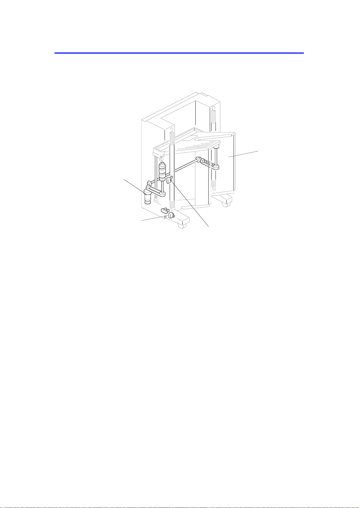
The sorter bin unit [A] is raised an d lowe red by the bin shift motor [B]. If th e
bin shift motor fails to stop, the bin unit drive powe r is cut by the upper or
lower limit switches [C] and [D].
C560D505.wmf
2-4
Page 16
[G]
15 November 1995 BIN UNIT
2.2 BIN MOVEMENT
[B]
[B]
[A]
[D]
C560D506.wmf
[C]
[C]
[A]
[E]
[C]
[F]
C560D507.wmf
[E]
C560D5098.wmf
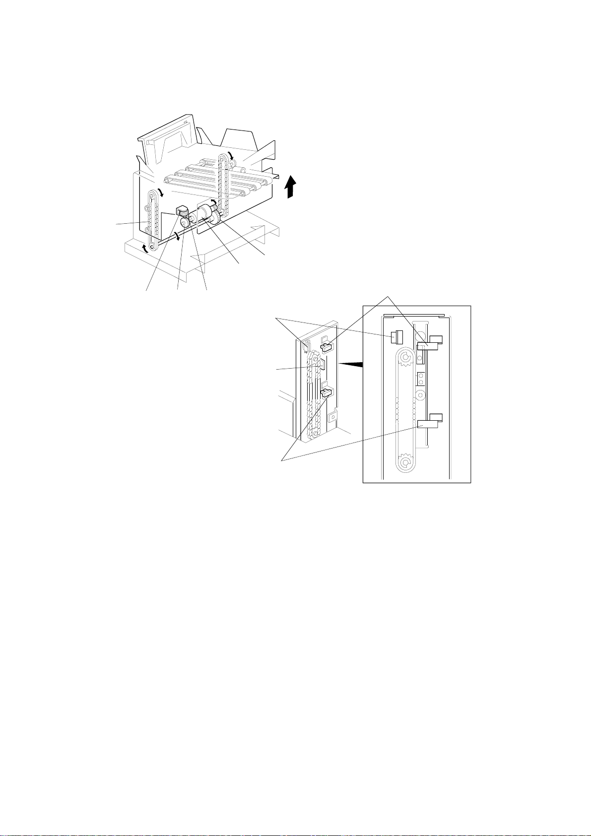
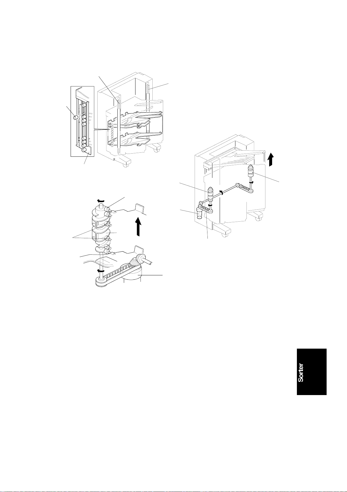
Each bin has a small roller [A] at each end. The bin un it is supp ort ed by
springs [B] which are attach ed to the sort er main body. There are two helical
wheels [C] on each side. The slit in the helical wheel engages the small
rollers [A] at both ends of each bin. The bin s are atta ched to the sorter main
body at the cutou ts in th e main body side plates [D] and by engaging the
small rollers to the helical wheels. The load on the helical wheels during liftin g
is decreased by the two springs.
The bin shift motor [E] rota te s t he helica l whee ls forward and in reverse
through the timing belt [F]. When the helical wheels rot ate, the small rollers
move up and down along th e gro oves [G] in the helical wheels. This enab les
the bin unit to move up and down.
2-5
Page 17
BIN UNIT 15 November 1995
[A]
[B]
C560D509.wmf
[C]
[A]
C560D511.wmf
C560D510.wmf
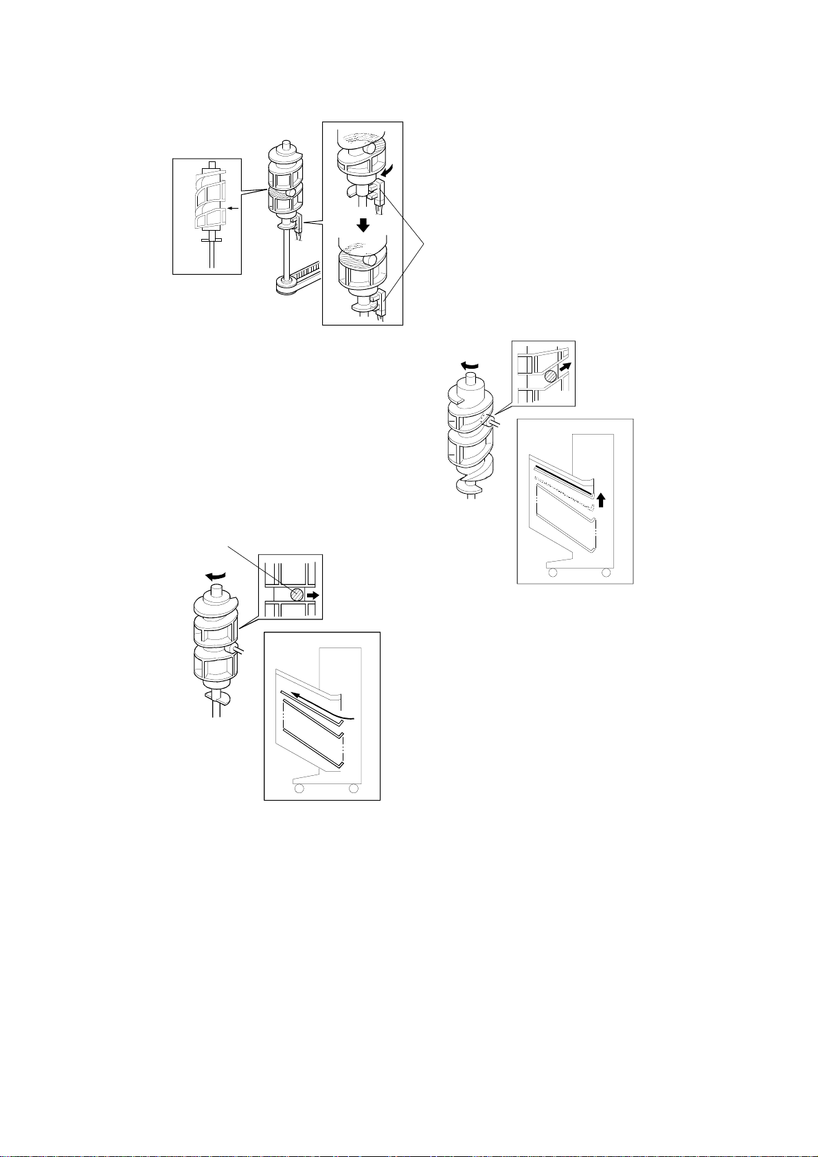
There is a flat portion [A] in the cen te r of the gro ove in each helical wheel.
Without this, the helical wheels would rotate in reverse at the bin stop
position due to the weig ht of th e the bin unit. The helical whee l home position
sensor [B] is actuated while the small rollers [C] are on the flat portion of the
helical wheel. The bin shift motor stops, and the bins do not move so that
paper can exit to the bin at this moment.
2-6
Page 18
15 November 1995 BIN UNIT
2.3 J OG GER BAR CONTROL
[A]
C560D512.wmf
C560D513.wmf
[E]
[E]
[D]
C560D514.wmf
[B]
[C]
The jogger bar [A] is driven by the jo gger ba r motor [C] (a stepper motor)
through the gear [D] . The jogger bar moves as shown in the illust rat ion
whenever paper is fed out to th e bin. Also the jogger bar moves and holds
the paper stack for stapling. Ordin arily, the jogger bar is at the home position.
It moves to the rear of th e sta ck (t he dista nce mo ved by the jogg er ba r
depends on the selected paper size [B]). Then, after jogg ing , the motor
moves the jogger bar back to its ho me po sitio n. The motor stops when the
actuator actuates the jogger bar home position sensor [E].
2-7
Page 19
BIN UNIT 15 November 1995
2.4 BIN/JAM SENSOR
[A]
[B]
C560D515.wmf
The bin jam sensor consists of an LED ([A]: light emitting element) and a
photo-transistor ([B]: lig ht receivin g ele men t). The sensor detects whether
there is any paper in the bins.
2-8
Page 20
15 November 1995 BIN UNIT
2.5 BIN UNIT HOME POSITION S ENS OR
[A]
[B]
[A]
C560D516.wmf
C560D517.wmf
[C]
[A]
[D]
C560D518.wmf
When the Print Start key is pressed or whe n all pape r left in the bin unit is
removed, the bin unit [A ] returns to the home position. The bin unit stops at
the home position when it actuates the bin unit home position sensor [B].
Even if the bin unit [A] overrun s due to someth ing wrong, the bin lower limit
[C] or bin upper limit [D] switch will cut the 24V line to the bin shift motor.
Then, the bin unit stop s. To reset this condition, turn the main switch off and
on.
2-9
Page 21
[B]
[E]
BIN UNIT 15 November 1995
2.6 BIN UNIT OBSTACLE SWITCH
[C]
[A]
C560D519.wmf
[D]
C560D520.wmf
If there is an obstacle [A] und er the bin unit [B] and the bin unit can no t be
lowered, the bin unit obstacle switch [C] cuts the 24V line to the bin shift
motor. This happens when the helica l wheel [ D] is rota ted by the bin shift
motor without moving the bins. In such a case, the helical wheel is raised by
the small rollers [E] and it pushes the bin unit obstacle switch [C].
2-10
Page 22
15 November 1995 STAPLE UNIT
3.
STAPLE UNIT
3.1 OVERVIEW
[A]
[B]
C560D521.wmf
The staple unit [A] stap les th e stack of paper in the bins. The staple unit shift
motor shifts the staple unit to the stap ling posit ion . The staple motor drives
the staple hammer only when the paper sensor [B] detects that there are
copies under the hammer. While th e bin unit is shif tin g up or down , th e sta ple
unit returns to the home position to pre vent the staple unit from interfering
with copies in the bins.
2-11
Page 23
[I]
STAPLE UNIT 15 November 1995
3.2 STAPLER
[C]
[F]
[E]
[D]
[G]
[B]
[A]
[H]
C560D535.wmf
The stapler motor [A] drives the sta ple sheet drive belt [B].
The staple sheets are fed under th e hammer [C] .
The stapler motor drives the staple hammer via gears [D], and an eccentric
cam [E] and link [F] at each side.
When the aligned copies have bee n bro ught to the sta pling position, the
stapler motor starts. When the cams comple te one rota tio n, the staple ho me
position sensor [G] is de-act ua ted. The stapler motor t he n sto ps.
When the paper sensor ([B] on the previo us pa ge) d oes not detect any
copies under the hammer, the stap ler mot or do es not tu rn on .
A paper sheet [H] with a not ch cut -out is positioned at the bott om of the
staple cartridge. Th is pap er she et is fed out after the last sta ple sheet. When
the leading edg e of the notch in the sheet is dete cte d by the staple end
sensor [I], the sorter stapler unit recognizes the stap le ne ar-e nd condition.
After the job is complet ed , the Add Staples indicator ligh ts on the print er
operation panel and the Print Start key is disabled whenever the staple sort
mode is selected.
2-12
Page 24
15 November 1995 STAPLE UNIT
3.3 S TAPLE R OPERATION
C560D523.wmf
C560D524.wmf
The above drawings illustrate th e motion of the stapler when copies are being
stapled.
3.4 S TAPLE JAM CONTROL
When a staple jam occurs in the staple unit, the ma chin e op era te s as follo ws:
1) The staple motor locks. As a result , the staple hammer cannot retu rn to
home position within 1 second.
2) The staple motor rotates in reve rse to return the staple hammer to home
position.
3) The printer detects a staple jam cond itio n.
2-13
Page 25

[B]
STAPLE UNIT 15 November 1995
3.5 S TAPLE SAFETY SWITCH
[A]
[C]
C560D525.wmf
If there is an obstruction such as a finger [A] at the sta ple posit ion pushing up
the actuator [B], the st aple safety switch [C] cuts the 24V line to the staple
motor.
2-14
Page 26

15 November 1995 STAPLE UNIT
3.6 S TAPLE UNIT SHIFT MECHANISM
[B]
C560D526.wmf
[B]
[B]
C560D527.wmf
[A]
C560D528.wmf
The staple unit shift motor [A] shifts the staple unit stand [B] to the stapling
position. Before moving the bin unit up or down, the st ap le unit shift motor
returns the staple unit st and to the home position to preven t the staple unit
from interfering with copie s in the bins.
2-15
Page 27

STAPLE UNIT 15 November 1995
3.7 STAPLE UNIT POSITION DETE CTION
[C]
[A]
C560D529.wmf
[B]
[D]
[C]
[A]
[B]
C560D530.wmf
The position of the staple unit is detected by the staple positio n switch [A]
and the staple unit movemen t switch [B]. When the staple unit is in the ho me
position [C], both the switches are off. When the staple unit is in the staplin g
position [D], the stapling posit ion swit ch is on and the staple unit movement
switch is off. While the staple unit is moving bet wee n th e two positions, both
the switches are on.
2-16
Page 28

[A]
15 November 1995 STAPLE UNIT
3.8 P APE R STACK HO LDI NG ARM
[A]
[C]
[B]
C560D531.wmf
[C]
[B]
C560D532.wmf
During stapling, th e jog ge r bar ho lds the stack of paper from the side and the
paper stack holding arm [A] holds the stack of paper from above. The paper
stack holding arm solenoid [B] turns on to lower the paper stack holding arm.
To prevent the paper sta ck holding arm from being damaged by th e bin unit if
the bin unit is shifted while the arm is hold ing the stack, the paper sta ck
holding arm switch [C] cuts off the 24V line to the bin shift motor.
2-17
Page 29

2ND TRANSPORT UNIT 15 November 1995
4.
2ND TRANSPORT UNIT
4.1 OVERVIEW
[A]
[C]
When the 20th copy has been fed to the 1st sorter, the bin unit [A] is at its top
position and the bin unit has raised the 2nd tran sport unit [B] to its ready
position. The 21st to 40 th copies are transported to th e 2nd sorter [C] through
the 2nd transport unit.
[B]
C560D534.wmf
2-18
Page 30

[B]
[C]
15 November 1995 2ND TRANSPORT UNIT
4.2 2 ND TRANSPORT BELT DRIVE MECHANISM
[F]
[G]
[E]
[A]
[D]
[F]
[D]
C560D533.wmf
The 2nd transport motor [A] drives th e tra nsp ort belt s [B] through the timing
belt [C] and transport rollers [D] . The motor has a timing disk [E], which the
2nd transport motor rotat ion sensor uses for monitoring and controlling the
2nd transport motor rotation speed. The 2nd transport fan motor [F] is
installed below this unit. This fan motor sucks air through the holes in the
transport belt to hold the paper on the tran sport belts.
The 2nd transport sensor [G] determines the 2nd sorter bin shift timing and
counts the copies by dete cting the leading and tra iling edg es of copies
passing through the sensor.
2-19
Page 31

SECTION 3
INSTALLATION
Page 32

15 November 1995 INSTALLATION PROCEDURE
1. INSTALLATION PROCEDURE
[C]
[B]
[D]
[A]
C560I500.img
C560I501.img
1.1 FIRST SORTER ONLY, OR FIRST AND SECOND SORTERS
NOTE: 1. When both the sorter and LCT are to be in sta lled, install the
LCT first. Otherwise it will be difficult to adju st th e LCT side
registration.
2. If the LCT has been previously insta lled, it is required to
change the positions of both the front and rear switch brackets
inwards. Remove the LCT unit from the printer and carry out
this step (refer to the LCT installation).
1. Turn off the main switch an d un plu g the power cord.
2. Make sure that the mach ine is secured to the table with 2 screws [A].
Also, make sure that the machine does not overhang th e ed ge of the
table.
3. Remove the Right Front Cover (loosen 2 screws and remove 2 screws)
and the Rear Cover (remove 7 screws).
NOTE: When installing the interface board [B] to the main board, the
right side connector of main bo ard shou ld to meet the connector
of the interface board.
4. At the front side of the machine, attach the Sorter Interface Board [B] to
the Main Board with 3 Locking Spacers [C] and connect the connector [D]
as shown in the diagram.
3-1
Page 33

INSTALLATION PROCEDURE 15 November 1995
[F]
[H]
[B]
[C]
[D]
[G]
C560I503.wmf
[E]
[A]
C560I502.img
C560I504.img
5. At the rear side of the machine, pass the Line Cable Con ne cto r harness
[A] and wire [B] through the hole [C] , con ne ct th e con nector [D] and
attach the Line Cable Connector [E] to the machine with 2 small screws
(M3 X 6). Secure the wire [B] with 1 screw and a to ot he d wash er [F] .
6. Remove the upper cover plate [G] on the Rear Cover. Reinstall the Right
Front Cover and the Rear Cover.
7. Remove the Delivery Table [H] (2 screws).
3-2
Page 34

[D]
15 November 1995 INSTALLATION PROCEDURE
[A]
[F]
C560I505.img
[B]
[E]
[C]
C560I506.img
C560I507.img
Note: Skip step 8 if the printer does not ha ve the Wing Guide Release
Lever [A].
8. Adjust the Wing Guid e Rele ase Lever [A] to the long position as shown in
the diagram.
9. Attach the Table Bracket Plate [B] to the side of th e ta ble with 1 screw
and 1 screw with a toothed washer [C] . Se cure the Stay Bracket [D] with
1 screw (left, left view) and 1 screw with a toothed washer [E] (rig ht, lef t
view).
10. Remove the two brackets [F] securing the sorter bins
(4 screws).
3-3
Page 35

[C]
INSTALLATION PROCEDURE 15 November 1995
[B]
[A]
[B]
[A]
C560I508.img
C560I509.img
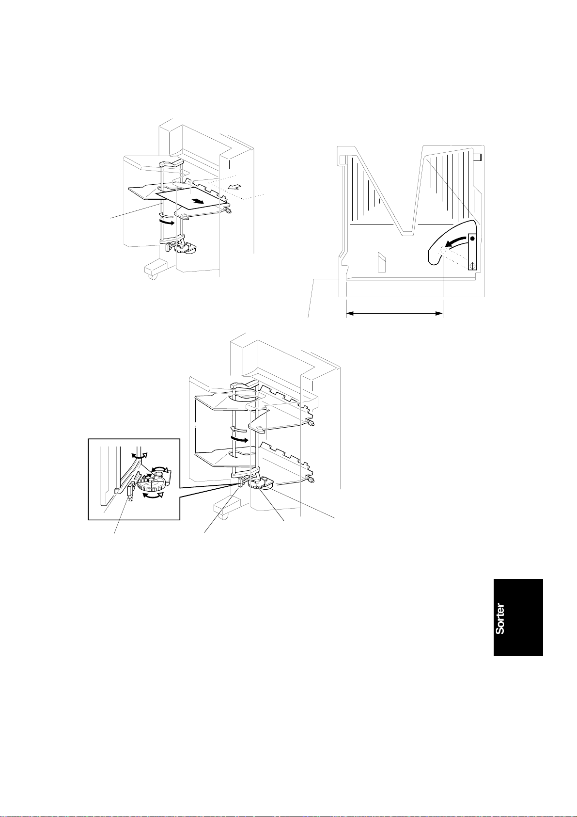
11. Raise the sorter into the upright po sitio n an d remove th e ta pe strips [A]
and the protection pads [B].
NOTE: Skip steps 12 to 28 if the 2nd sort er is not in sta lled.
12. If you are installing th e second sorter at the same time, carry o ut the
following procedure.
Plug in the po wer cord of the sorter unit.
Raise the bin unit of the sorter unit to the top (to the 21 st bin ) by pre ssing
SW3 on the sorter PCB [C] as shown in the diag ram.
Unplug the power cord after step 12.
NOTE: Disregard this procedure if you are installing only the first sorter.
13. Turn off the main swit ch of the machine and unplug the power cord . Also,
unplug the power cord of the first sorter.
NOTE: It is easier to carry out steps 14 to 16 if the first sorter is laid
down.
3-4
Page 36

15 November 1995 INSTALLATION PROCEDURE
[D]
[C]
[B]
[A]
C560I510.img
C560I507.img
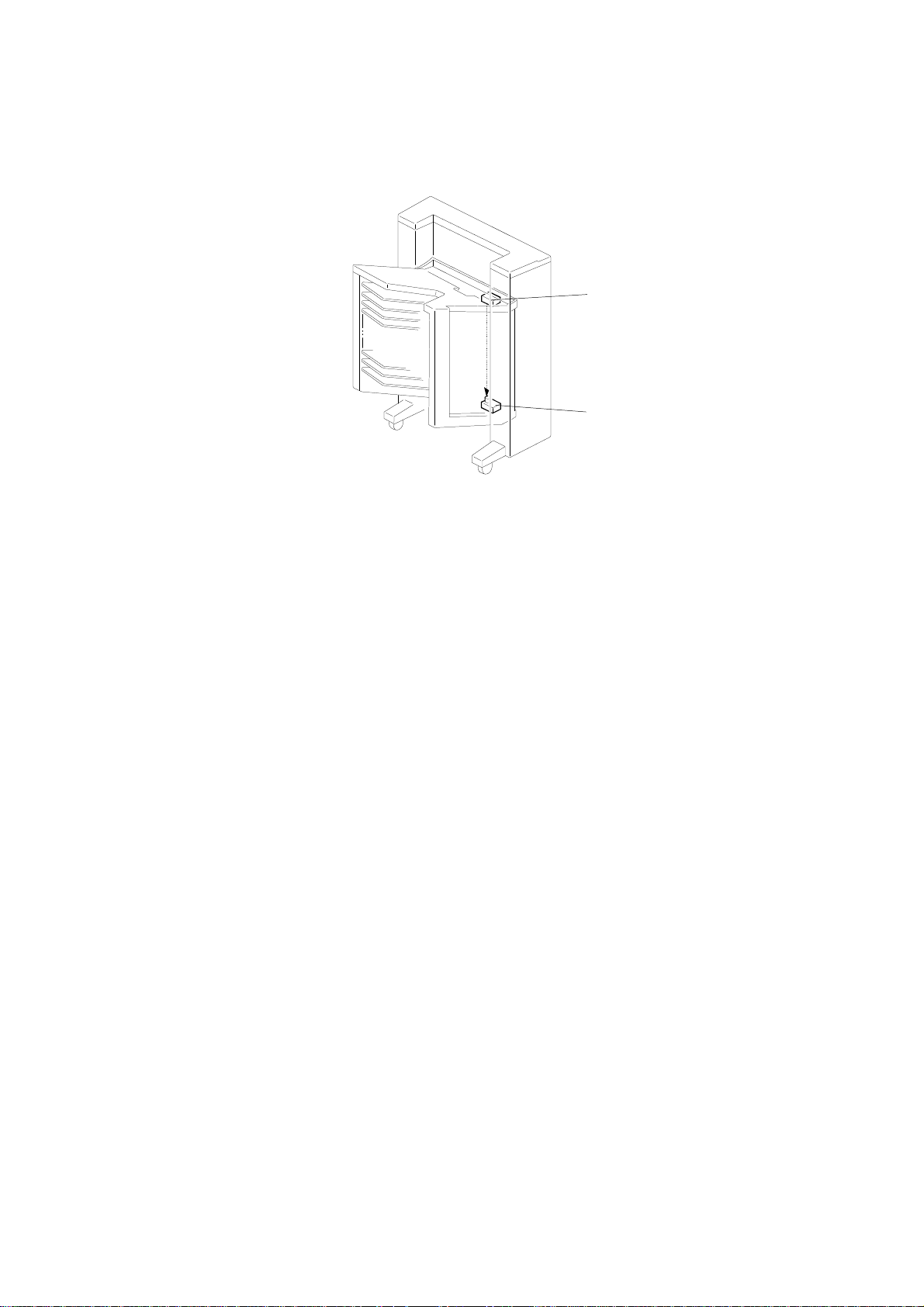
14. Remove the Bin Cover [A] (3 screws) f rom th e first sorter.
NOTE: Keep 2 screws and discard the Bin Cover. You will need the
screws later in step 19.
15. Remove the Bottom Cover [B ] (3 screws) fro m t he first sorter. Pass the
connector [C] thro ugh the cut-out as of the botto m co ver sho wn in the
diagram.
16. Reinstall the Bott om Cover with the 3 screws that you remo ved in the
previous step.
17. Remove the 2 brackets [D] securin g the sorter bins of the second sorte r
unit (4 screws).
3-5
Page 37

[H]
INSTALLATION PROCEDURE 15 November 1995
[A]
[B]
[A]
C560I508.img
[J]
[D]
[E]
[E]
[F]
[I]
[C]
C560I513.img
[G]
C560I514.img
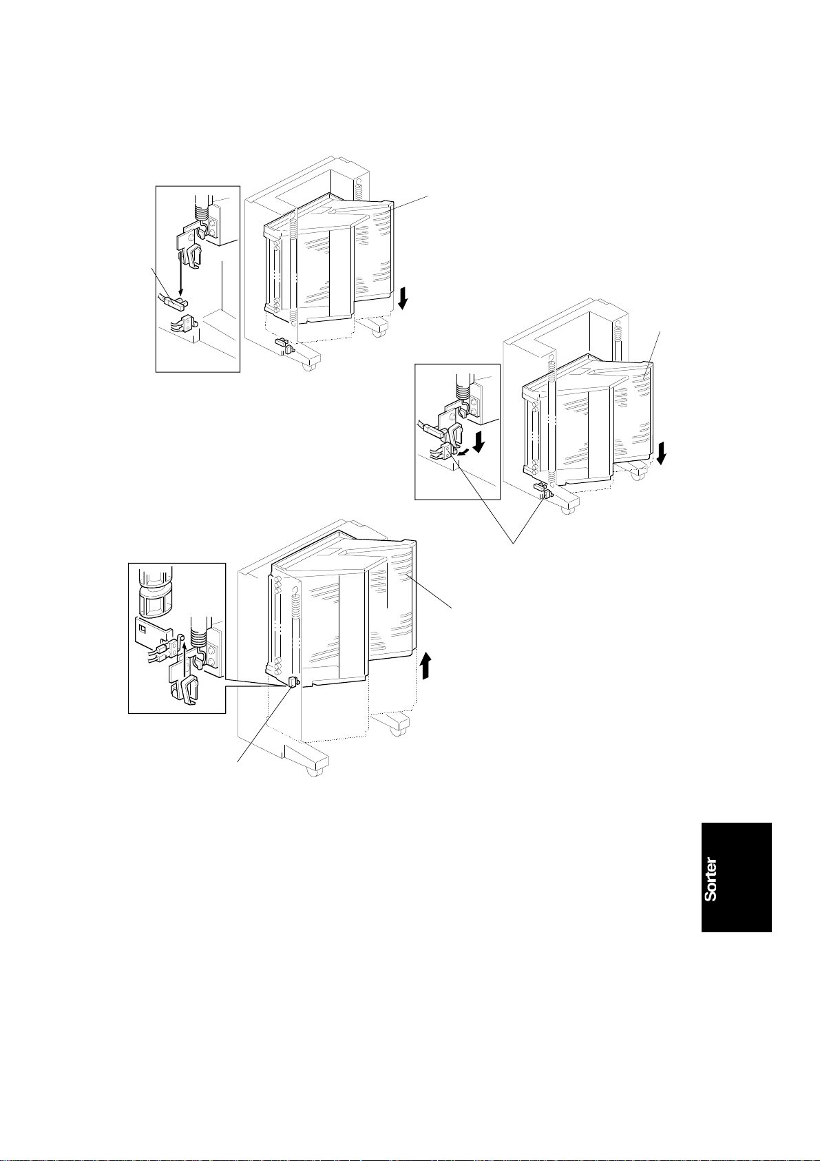
18. Raise the second sorte r unit into an upright position and remo ve the tape
strips [A] and the protection pa ds [B ].
19. Attach the Holding Tape [C] to the first sorte r unit with the 2 screws that
you removed in step 14. Attach the Joint Bracket [D] to the Bottom Plate
with 1 screw (left, left view) and 1 screw wit h a to ot he d wash er [E] (right,
left view).
20. Attach the Front Joint Stay [F] with 2 long screws (M4X10) an d 1 to othed
washer [G]. Atta ch the Rear Joint Stay [H] with 1 screw wit h a to othed
washer [I] and 1 long screw (M4X10). Put the Joint Stay Cover [J] on top
but do not screw it into place.
3-6
Page 38

C560I515.img
15 November 1995 INSTALLATION PROCEDURE
[I]
[J]
[C]
[H]
[E]
[B]
[I]
[K]
[M]
[L]
[D]
[A]
[F]
[O]
[K]
C560I516.img
[N]
C560I517.img
21. Attach the Seco nd Sort er Ad ap ter Unit [A] to the Joint Bracke t [B ] with 1
screw and 1 screw with a toothed wash er [C] . (In sert the 2 positioning
tabs [D] into the docking holes [E].)
Connect 2 connectors [F] as shown in the diagram.
NOTE: When attaching the Fron t Joint Stay [G], the 2 rollers [H] on th e
Adapter Unit should be insid e the guide rails [I] on the seco nd
sorter.
22. Attach the Front Joint Stay [G] and the Rear Joint St ay [J] to the 2nd
sorter with 3 long screws (M4X10) and 2 toothed washers [K] .
23. Remove 2 screws on the rear side of the sorters. (Discard these screws.)
Attach the Upper Joint Stay [L] with 2 long screws (M4X10) a nd 2 toothed
washers [M].
24. Remove the Holding Tape [N] and add it to the rear side of the first sorter
for any required later use.
25. Attach the Stopp er Screws [O] to the second sorte r.
3-7
Page 39

INSTALLATION PROCEDURE 15 November 1995
[B]
[B]
[A]
[C]
C560I518.img
[E]
[F]
[G]
[H]
C560I519.img
[ I ]
C560I520.img
26. Secure the Joint Stay Cover [A] that you positioned in step 10 with 2
screws and 1 screw with a toothe d wash er [B].
27. Slide the Lower Front Cover [C] up th e guide rails [D] and secure it with 1
screw and 1 screw with a 1 toothe d wash er [E]. Attach the Lower Re ar
Cover [F] in the same way with 1 screw and 1 screw with a to ot he d
washer [G]. Attach th e Secon d So rte r Bot to m Co ver [H] with 3 screws
and 1 screw with a toothed wash er [G].
28. Connect the 2nd Sorter Line Cable [ I ] into the 1st so rte r.
3-8
Page 40

15 November 1995 INSTALLATION PROCEDURE
[B]
[A]
C560I521.img
C560I522.img
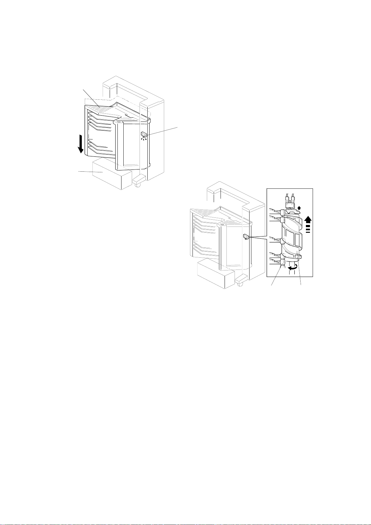
29. Remove the tape strips [A] on the So rte r Adapt er Unit.
30. Holding the uppe r bod y of th e Ad ap ter Unit [B] as shown in the diagram,
lift it up to the highest position (there should be three clicks).
3-9
Page 41

INSTALLATION PROCEDURE 15 November 1995
[F]
[E]
[H]
[G]
[D]
[J]
[A]
[B]
[C]
C560I523.img
[ I ]
C560I524.img
31. Connect the connector [A] from the Sorter to the Ada pt er Unit . Hook the
docking tabs [B] on the cutouts [C] and secure the Adapter Unit to the
Sorter Unit with 3 screws and 1 screw with a toothed washer [D].
32. Attach the Front Side Cover [E] with 2 screws and 1 screw with a toothed
washer [F]. Attach the Rear Sid e Cover [G] with 2 screws and 1 screw
with a toothed wash er [H]. Attach the Sorter Table Stay [I] to the Sorter
with 1 screw and 1 screw with a toothed washer [J].
3-10
Page 42

15 November 1995 INSTALLATION PROCEDURE
[C]
[B]
[A]
[A]
[B]
[A]
C560I525.img
[E]
[D]
C560I526.img
C560I527.img
33. Secure the Sorte r Un it to the machine with 3 wing nuts [A] and 2 toothed
washers [B]. Make sure th at the Positioning Pin [C] fits through the hole in
the Adapter Unit.
34. Connect the Line Ca ble [D] from the Sorter Unit to the mach ine.
Note: Skip step 35 when the LCT is installed .
35. Open the Paper Feed Table and place the Movement Eliminators [E] on
both sides of the Paper Table.(When the LCT is installed).
3-11
Page 43

A3_________
B4_________
INSTALLATION PROCEDURE 15 November 1995
[A]
C560I529.wmf
[B]
[C]
C560I528.img
4. Pull the lock lever right and close the tray. After removing th e jam me d pa pe r, press t he rese t bu tton on the operation
panel.
4. Tirer la manette de dro ite et fe rm er le plat eau. Après avoir retiré le pap ier coino é, appuyer sur la touche Reset sur le
tableau de bord.
4. Raste nach rechts zlehen und Auff an gtlsch schließen. Nach Entfern un g de s Paple rst au s die Rücksetztaste am
Bedlenungsfeld drücken
[D]
36. Place 4 decals [A] [B] [C] and [D] on the machine.
Note: 1. Skip placing the decal [A] if the printer has a guidance display.
2. Skip placing the decal [C] if the printer does not have the win g
guide release lever.
C560I530.img
C560I531.wmf
3-12
Page 44

[C]
15 November 1995 INSTALLATION PROCEDURE
[B]
[A]
C560I532.img
C560I533.img
Note: Step 37 is only for the U.S.A. version.
37. Place the caution deca l [ A] on th e mach ine table (Except C560-22,
C560-27).
38. Neatly stack the prin tin g pa pe r o n th e ta ble and adjust the Side Plate s.
39. Adjust the position of the End Fence [B] and the Side Fences [C] on the
Non-Sort Tray [D] accordin g to the print ing paper size.
40. Plug in the power cord of the Sorter Unit.
The socket-outlet shall be installed near the equipment and shall be
easily accessible.
41. Plug in the power cord of the ma chin e an d tu rn on the main switch.
42. Access the SP mode and chan ge the setting of SP7 from 0 to 1.
[D]
43. Make some test prints to check the machine.
3-13
Page 45

[C]
INSTALLATION PROCEDURE 15 November 1995
1.2 ADDING A SECOND SORTE R
[B]
[A]
C560I533.img
1. Follow steps 12 to 28 of the first sorter insta llat ion.
2. Neatly stack the printing paper on the table and adju st th e Side Plates.
3. Adjust the position of the End Fence [A] and the Side Fences [B] on the
Non-Sort Tray [C] to match the printing paper size.
4. Plug in the power cord of the 1st Sorter Unit.
The socket-outlet shall be installed near the equipment and shall be
easily accessible.
5. Plug in the power cord of the machin e an d turn on the main switch.
6. Store the sorter set tin gs in the machine using the Service Program Mode.
7. Make some test prints to check the machine.
3-14
Page 46

SECTION 4
SERVICE REMARKS
Page 47

15 November 1995 SERVICE REMARKS
1. SERVICE REMARKS
1. Disconnect the power plugs of the main frame and the sorter during
maintenance.
2. If a circuit breaker or a fuse open s, check and remove the cause of the
overcurrent before rese tting the breaker or replacin g th e fuse.
3. Do not operate SW2 or SW3 on the sorter ma in con tro l b oard to rise or
lower the bin unit if the 1st transp ort unit is installed. There is a danger of
the 1st transport unit dropping suddenly.
4. Do not transport th e mach ine up or down stairs or over a step while the
main frame and sorter unit are connected. Otherwise, the connecting rails
will be deformed.
5. Do not put your hand under the master eject unit during machine
operation, because it may get trapped when the 1st transport unit lifts up .
6. Do not put your hand or leg on the 2nd transport unit during machine
operation.
4-1
Page 48

LUBRICATION POINTS 15 November 1995
2. LUBRICATION POINTS
Lubricate after removing adhering ink and paper dust eve ry two years.
Section Item Type
Sorter Helical wheels Grease (G-501)
Bin shift motor pinion gears Grease (G-501)
Bin rollers Grease (G-501)
Bin roller guide Grease (G-501)
Bin guide plates (A in the illustration below) Oil (Cosmo Allpus 56)
1st/2nd transport
unit
Transport belt drive pinion gears Grease (G-501)
Paper delivery table drive pinion gears Grease (G-501)
A
C560M500.wmf
4-2
Page 49

15 November 1995 SWITCH/VR/LED TABLES
3. SWITCH/VR/LED TABLES
SWITCHES
Switch No. Function Remarks
SW 1 DIP switches for
test mode
SW 2 Bin unit down Press this switch to lower the bin unit.
SW 3 Bin unit up Press this switch to raise the bin unit.
Do not operate SW2 or SW3 to raise or lower the bin unit when the 1st
transport unit is installed . The re is a dange r of th e 1st transport unit dropping
suddenly.
VRs
VR No. Function Remarks
VR 100 Bin/jam sensor
adjustment
Refer to the test mode section.
Refer to the test mode section.
LEDs
LED No. Function Remarks
LED 100 Bin/jam sensor Use to check the bin/jam sensor or the staple end
sensor. Refer to the test mode section.
4-3
Page 50

TEST MODE 15 November 1995
4. TEST MODE
The following tests can be use d to test sorter operation instead of using SP
modes, only when the sorter is not conne cte d to the main fra me. The
following table shows t he DI P SW 1 set ting for each test mode.
Test
No.
0 Normal mode (Default setting) OFF OFF OFF OFF OFF OFF
1 Bin/jam sensor check OFF OFF OFF OFF OFF ON
2 1st transport motor test OFF OFF OFF OFF ON OFF
3 Staple end sensor check OFF OFF OFF OFF ON ON
4 2nd transport motor test OFF OFF OFF ON ON ON
5 Sorter unit operation test OFF OFF ON OFF OFF ON
6 Paper delivery table motor test OFF OFF OFF ON OFF OFF
7 Sort operation test OFF OFF OFF ON OFF ON
Function DIP SW 1 (Sorter Main Board)
123456
Disconnect the power plugs of th e sort er and main frame while changing the
DIP switch settings.
1. Bin/jam sensor check
This test is equivalent to main frame input check mode (SP130) No. 74 (1st
sorter) or No. 90 (2nd sorter).
1-1. Confirm that LED 100 is off.
1-2. Put a sheet of tran sluce nt paper (TA80) on the top bin.
1-3. Confirm that LED 100 blinks.
1-4. If the LED indicatio n is incorre ct, adjust using VR 100.
2. 1st transport motor check
This test is equivalent to ma in fra me ou tput check mode (SP131) No. 61.
2-1. Press the manual st aple key to turn on the 1st transpo rt mot or.
2-2. Press the manual st aple key ag ain to stop the motor.
NOTE: E-21 will be displayed if the 1st transport motor speed is abnormal.
4-4
Page 51

15 November 1995 TEST MODE
3. Staple end sensor check
This test is equivalent to main frame input check mode (SP130) No. 70 (1st
sorter) or No. 86 (2nd sorter).
3-1. Confirm that LED 100 is off when th ere are no stap les.
3-2. Put a sheet of tran sluce nt paper (TA80) on the top bin.
3-3. Confirm that LED 100 blinks whe n th ere are sta ples present.
If the LED indication is incorre ct, check the circuit and replace any defect ive
parts.
4. 2nd transport motor test
This test is equivalent to ma in fra me ou tput check mode (SP131) No. 62.
4-1. Press the manual st aple key to turn on the 2nd transport motor.
4-2. Press the manual st aple key ag ain to stop the motor.
NOTE: The bins return to home position, then rise to the uppermost position.
If the staple cover or 2nd transport cover is opened, the motor stops.
E-34 will be displayed if the 1st transport motor speed is abnormal.
5. Sorter unit operation test
Main frame output ch eck mod e (SP131) No. 71 is also a sorter operatio n test.
5-1. Press the manual staple key to start the sort with stapling simulation .
5-2. Press the manual st aple key ag ain to stop the machine operation.
6. Paper delivery table motor test
This test is equivalent to ma in fra me ou tput check mode (SP131) No.60 .
6-1. Press the manual staple key to start the paper delivery table motor. The
paper delivery table moves betwe en the sort po sitio n and th e no n-so rt
position.
6-2. Press the manual st aple key to stop the motor.
4-5
Page 52

TEST MODE 15 November 1995
7. Sort operation test
Main frame output ch eck mod e (SP131) No. 71 also a sorter operat ion test.
7-1. Press the manual staple key to start the sort staple mode simulation . The
machine works as if 20 sets (40 sets if the 2nd sorter is installed) of 5 A3
sheets are sorted and sta pled after the proof prin t is delivered.
7-2. Press the manual st aple key ag ain to stop the machine operation.
NOTE: If the staple cover or the 1st transport cover is ope ne d, the operation
stops.
4-6
Page 53

SECTION 5
REPLACEMENT AND
ADJUSTMENT
Page 54

15 November 1995 REPLACEMENTS
1. REPLACEMENTS
1.1 PAPER DELIVERY TABLE UNIT REMOVAL
[A]
[D]
[C]
[B]
[H]
[I]
C560R500.wmf
[F]
[G]
[E]
1. Remove the transport fa n un der cover [A]. Remove the delivery table
drive unit’s right under cover [B].
2. Remove the front cove r [C] an d th e rear cover [D] of the paper delive ry
table drive unit.
3. Remove the screw [E] holding the grounding wire.
4. Remove the 15-pin connecto r [ F] and pu ll the wire wit h two clamps [G]
away from the machine.
5. Manually release the paper delivery motor stopper [H] . Carefully lower the
paper delivery table unit by turning the paper delivery motor [I].
CAUTION:
I
Be careful not to have your hand caught when the paper deli ve ry table
moves down.
C560R501-1.wmf
5-1
Page 55

[K]
REPLACEMENTS 15 November 1995
[K]
[J]
[L]
[L]
[K]
C560R502.wmf
6. Remove the actuator bracket [J] (2 screws). Remove the four slide guide
rollers [K] while supporting the delive ry tab le unit.
7. Remove the 4 screws [L] (2 fron t an d 2 rear) holding the chain bracke t to
the paper delivery table unit.
8. Remove the paper delivery table unit .
5-2
Page 56

15 November 1995 REPLACEMENTS
1.2 TRANSPORT BELT UNIT REMOVAL
[H]
[A]
[G]
[B]
[I]
[B]
C560R503.wmf
[F]
[H]
C560R543.wmf
[G]
[E]
[C]
[D]
C560R501-2.wmf
1. Raise the paper delivery t ab le un it to the high est position.
2. Remove the transpo rt fa n un de r cover an d the lower right cover of the
delivery table drive unit.
3. Remove the stepper screw [A] supporting the paper delivery table open
link.
4. Remove the two stepper screws [B] supporting the paper delivery tab le.
Remove the paper delivery table .
5. Remove the screw [C] holding th e gro un din g wire. Pull the wire with two
clamps [D] away from the machine an d disco nn ect the 15-pin connector
[E].
6. Disconnect the 4-pin connector [F].
7. Remove the two stays [G].
8. Remove the 4 screws [H] holdin g th e transport belt unit.
9. Remove the transport belt un it [I ].
5-3
Page 57

REPLACEMENTS 15 November 1995
1.3 BIN UNIT REMOVA L
[A]
C560R505.wmf
[B]
C560R506.wmf
1. Raise the paper delivery table un it to the high est posit ion (f or remo val of
the 1st sorter bin unit only).
2. Raise the bin unit to th e up per p osit ion using output check mode (SP1 31 )
No. 63 (1st sorter) or 67 (2nd sorter).
CAUTION:
I
Do not use SW3 on the sorter main board to raise the bin unit when
the 1st transport unit is installed. There is a danger of the 1st
transport unit dropping suddenly.
3. Disconnect the power plugs of th e sorter an d the prin te r’s ma in body.
4. Remove the upper cover, front cover, and the rear cove r.
5. Remove the front and rear springs [A] of the bin unit .
6. Remove the frame holder [B ] (2 screws).
5-4
Page 58

15 November 1995 REPLACEMENTS
[D]
[F]
[C]
C560R507.wmf
[E]
[G]
C560R508.wmf
7. Remove the power cord unit [C] (3 screws) (1st sorter on ly).
NOTE: The connectors [D] of the 115V machines cannot be
disconnected. Allow the powe r cord un it to hang fro m t he
harness.
8. Remove the cable holder [E ] (2 screws).
9. Remove the two screws [F] holding the grou nd ing wires. Disconnect the
three connectors [G].
5-5
Page 59

REPLACEMENTS 15 November 1995
[C]
[B]
[A]
C560R509.wmf
C560R510.wmf
[D]
[B]
C560R511.wmf
10. Manually turn the bin shift motor [A] while pushing up the bin unit un til all
the bin rollers [B] are above the helical cam [C].
11. Remove the bin unit.
NOTE: When reinstalling the bin unit, check th at each bin roller [B] is set
properly in the roller guide [D].
5-6
Page 60

15 November 1995 REPLACEMENTS
1.4 BIN REMOVAL
[A]
[B]
C560R512.wmf
[F]
[C]
[D]
C560R513.wmf
[E]
[G]
C560R514.wmf
1. Remove the bin unit (see Bin Unit Remova l).
2. Remove the dummy bin under cover [A] . Remo ve the dummy bin [B] (4
screws).
3. Take the guide bar [C] off the hold er [D] , an d remove it.
4. Remove the bin roller guide plate [E] (2 screws).
5. Remove all the bin rollers [F] and remo ve th e bin s.
NOTE: Do not loosen the screw that holds th e bin unit guide shaft [G]. If you
must move the guide shaft, mark the screw position before loosening
the screw.
5-7
Page 61

[C]
REPLACEMENTS 15 November 1995
1.5 JOGGER BAR UNIT REMO VAL
[B]
C560R515.wmf
[A]
[E]
C560R517.wmf
[D]
C560R516.wmf
1. Remove the bin unit.
2. Remove the dummy bin under the cove r (2 scre ws). Remo ve th e du mmy
bin (4 screws). See Bin Removal.
3. Remove the jogger bar holder [A ] (1 screw).
4. Unhook the spring [B ] an d slide out the jogg er ba r unit [C].
NOTE: When reinstalling the jogger bar, be sure to insta ll t he spring plates
[D and E] correctly as shown above.
5-8
Page 62

15 November 1995 REPLACEMENTS
1.6 BIN SHIFT MOTOR REMOVAL
[A]
[C]
[B]
C560R518.wmf
1. Remove the upper cover and rear cover of the sorter unit.
2. Remove the E-ring [A] on the bin shift motor [B] shaft.
3. Remove the pin [C] and remove the bin shif t motor (4 screws).
5-9
Page 63

REPLACEMENTS 15 November 1995
1.7 HELICAL WHEEL REMOVAL
[C]
[A]
[E]
C560R519.wmf
[B]
[D]
C560R520.wmf
1. Lower the bin unit to the bottom position using output check mode
(SP131) No. 66 (1st sorter) or 70 (2nd sorter).
CAUTION:
I
Do not use SW2 on the sorter main board to lower the bin unit when
the 1st transport unit is installed. There is a danger of the paper
delivery unit dropping suddenly.
NOTE: Do not remove both front [A] an d rea r [B] helical wheels at the
same time. The bin unit will drop.
- Front helical wheel -
2. Remove the holder [C] (2 screws) and remove the helical wheel.
- Rear helical wheel -
2. Remove the helical wheel home position sensor bracket [D] (2 screws).
3. Remove the holder [E] (2 screws) and remo ve the helical wheel.
5-10
Page 64

15 November 1995 REPLACEMENTS
1.8 STAPLE UNIT REMOVAL
[E]
[A]
C560R521.wmf
[B]
1. Remove the upper cover and the front cover of the sorter unit.
2. Remove the inner cover [A] (3 screws).
3. Remove the screw [B] holding the grounding wire.
4. Disconnect the connector [C].
5. Loosen the wing nut [D] and re move the stap le un it [E].
[D]
[C]
C560R522.wmf
5-11
Page 65

[C]
REPLACEMENTS 15 November 1995
1.9 STAPLE MOVEMENT UNIT REMO VAL
[B]
[A]
C560R523.wmf
[E]
[D]
C560R524.wmf
1. Remove the upper cover, fro nt co ver and the inner cover.
2. Remove the staple unit (see Staple Unit Removal).
3. Remove the lower right cover.
4. Disconnect the 3-pin connector [A] for the staple position sensor. Cut the
harness clamper [B].
5. Mark the bracket position [C].
6. Disconnect the 5 connectors [D] and remove the staple movement unit
[E] (3 screws).
5-12
Page 66

15 November 1995 REPLACEMENTS
1.10 PAPER STACK HOLDING ARM SO LENOID REMOVAL
[D]
[A]
[F]
[B]
[C]
C560R525.wmf
[E]
- 1st sorter -
C560R526.wmf
1. Disconnect the 1st transport unit from th e prin te r.
2. Disconnect the 1st transport unit from th e 1st sorte r.
3. Remove the upper cover and the front cover of the sorter.
4. Remove the inner cover. Remove th e staple unit (see Staple Unit
Removal).
5. Remove the right upper cover [A] (5 screws).
6. Remove the bracket [B] (3 screws).
7. Disconnect the two connectors [C] of the paper stack holding arm
solenoid.
8. Remove the solenoid bracket [D] (2 screws).
9. Remove the paper stack holding arm solenoid (2 screws) from the
bracket.
- 2nd sorter -
1. Disconnect the 2nd transport unit from the 2nd sorter.
2. Remove the upper cover and the front cover.
3. Remove the upper right cover and the lower right cover.
4. Disconnect the two connectors [E] and remove the paper stack holding
arm solenoid [F].
5-13
Page 67

[B]
[C]
ADJUSTMENTS 15 November 1995
2. ADJUSTMENTS
2.1 1ST TRANSPORT UNIT SO RT PO SI TI O N ADJUS TMENT
[A]
C560R527.wmf
Purpose: To ensure proper pape r fee d to the 1st sort er un it.
Adjustment Standard: 87.4 ± 0.2 mm
1. Access output check mode (SP131) and select No. 60.
2. Hold the Print Start key until the paper de livery ta ble stop s at the
uppermost position.
3. Disconnect the sorter power plug and remove the rear cover [A] of the 1st
transport unit.
4. Measure the distance between the notch [B] and the top of the pap er
table drive unit. The specified dist an ce is 87. 4 ± 0.2 mm.
5. If the distance is not wit hin the specification, loosen the screw holding the
slitter bracket [C] and adjust the bracket position .
5-14
Page 68

15 November 1995 ADJUSTMENTS
2.2 PAPER DELIVERY MOTO R STOPPER POSITION
ADJUSTMENT
[A]
[A]
[C] [B]
C560R528.wmf
Purpose: To ensure that th e stopper keeps the delivery unit in position when
the paper delivery table motor is off.
Adjustment standard: 17.5 ± 0.5 mm
1. Remove the fan cover and th e the under cover.
2. Measure the distan ce be twe en the motor [A] and the gear [B]. The
specified distance is 17.5 ± 0.5 mm.
3. If the distance is not within the specification, loosen the Allen screw [C ]
and adjust the gear position.
5-15
Page 69

[A]
ADJUSTMENTS 15 November 1995
2.3 TRANSPORT MOTOR PINION GEAR POSITION
ADJUSTMENT (1ST AND 2ND)
[C]
[B]
C560R529.wmf
Purpose: To ensure proper enga gement between the pinion gears.
Adjustment Standard: 3.5 ± 0.1 mm
1. Remove the transport belt un it (see Transport Belt Unit Removal).
2. Measure the distan ce be twe en the pinio n ge ar [A ] an d the motor [B]. The
specified distance is 3.5 ± 0.1 mm.
3. If the distance is not within the specification, loosen the Allen screw [C ]
and adjust the gear position.
5-16
Page 70

15 November 1995 ADJUSTMENTS
2.4 TRANSPORT MOTOR POSITIO N ADJUS TMENT
(1ST AND 2ND TRANSPORT UNIT)
[A]
[B]
C560R530.wmf
Purpose: To ensure proper tra nsmissio n of force from the motor to the belts.
Adjustment Standard: 4 mm when a 100 g pre ssure is applied.
1. Remove the transport belt un it (see Transport Belt Unit Removal).
2. Apply a 100 g pressure to the center of the belt [A]. Make sure the belt
deflects 4 mm.
3. If the distance is not within the specif ication, loosen the two screws [B]
and adjust the transp ort motor bracket position.
5-17
Page 71

ADJUSTMENTS 15 November 1995
2.5 JOGGER BAR HOME PO SI TI O N SENSOR POSITION
ADJUSTMENT
[B]
[A]
C560R531.wmf
[C]
C560R532.wmf
Purpose: To ensure that the paper st acks in th e bin s are arranged properly.
Adjustment Standard: 315.5 mm
1. Confirm that the distance betwe en the jogger ba r [A] and the plat e [B ] is
315.5 ± 0.5 mm.
2. If the distance is not wit hin the specification, loosen the screw holding the
jogger bar H. P. sensor bracket [C] an d adjust the sensor position.
• To adjust the sensor position for the 1st sorter, raise th e bin s to the
highest position using output check mode (SP131) No. 63.
• To adjust the sensor position for the 2nd sorter, remove the bin’s bot-
tom cover.
5-18
Page 72

15 November 1995 ADJUSTMENTS
2.6 BIN UNIT OBSTACLE SWITCH ADJ USTME NT
[A]
[B]
[C]
C560R533.wmf
Purpose: To ensure that the bin shift motor stops immediate ly when
an obstacle interrupts the bin’s downward movement.
Adjustment Standard: 1.5 mm
1. Remove the upper cover and the front cover.
2. Confirm that the distance betwe en the switch act ua to r [A] and the top of
the helical wheel [B] is 1.5 mm.
3. If the distance is incorrect, loosen the two screws [C] holding the switch
bracket, and adjust the switch position.
5-19
Page 73

ADJUSTMENTS 15 November 1995
2.7 HELICAL WHEEL POSITIO N ADJUS TMENT
[A]
[D]
[C]
[B]
C560R535.wmf
Purpose: To ensure that the bins keep level du ring vertical movement.
1. Remove the upper and lower rear sta ys.
2. Remove the upper cover, front cover, and re ar cove r.
3. Confirm that the positions of the meta l plat es [A] on the front and rear
helical cams are as shown in the illustrat ion . At this time, the pins [B] on
the helical cams should be parallel to each other.
4. If the relationship of the two helical wheel positions is incorrect, remove
the bin shift motor rotation sensor bracket (near the pulse disk
immediately below the bin shift motor; 1 screw). Loosen the 4 screws
that hold the bin shift motor [C]. Change the relatio nship of the pinion
gears [D] until the helical wheel positions are correct.
5-20
Page 74

[B]
[A]
15 November 1995 ADJUSTMENTS
2.8 HELICAL CAM HOLDER POSITIO N ADJUS TMENT
[C]
C560R534.wmf
Purpose: To ensure that th e he lical wheel moves smoothly and the bin
obstacle switch functions properly.
Adjustment standard: 0.4 mm to 0.5 mm
1. Remove the upper cover and the front cover.
2. Confirm that the gap between the helical wheel [A] and the bearing [B] is
0.4 mm to 0.5 mm.
3. If the gap is not within the specificat ion , loo sen the two screws [C] and
adjust the helical wheel holder position.
5-21
Page 75

ADJUSTMENTS 15 November 1995
2.9 STAPLE POSITION ADJUS TMENT
[A]
[B]
C560R536.wmf
C560R537.wmf
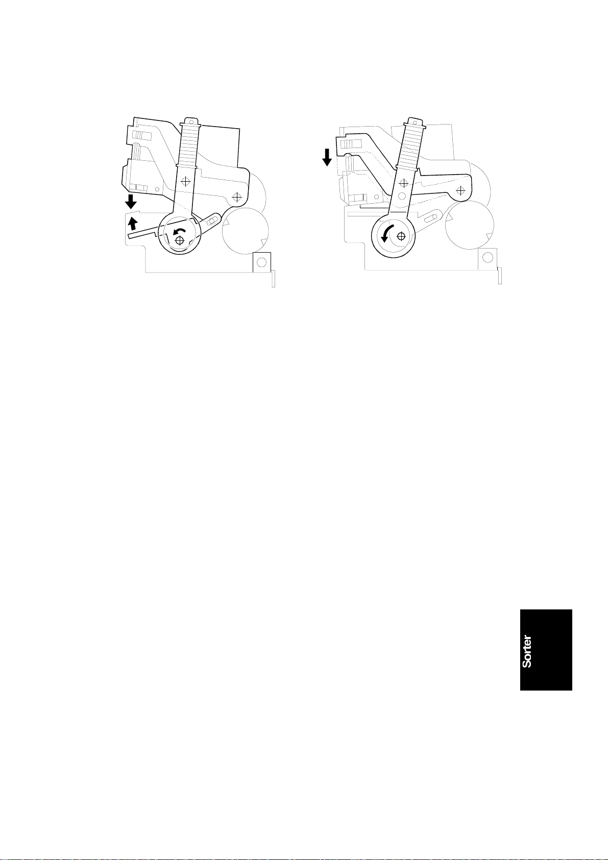
NOTE: Before changing the staple position, mark the original po sitio n on the
bracket.
1. Remove the staple unit (see Staple Unit Removal).
2. Loosen the 3 screws (1 front [A] and 2 rear) holding the stap le un it to the
bracket [B].
3. Change the position of th e sta ple unit on the bracket. The re lat ionship
between the bracket position and the staple positio n is as shown in the
illustration (black and white arrows).
5-22
Page 76

15 November 1995 ADJUSTMENTS
2.10 STAPLE POSITI ON SWITCH ADJUSTMENT
[D]
[B]
[C]
[A]
C560R538.wmf
c560d528.wmf
Purpose: To ensure that th e staple position sensor det ect s t he stap le
position properly.
Adjustment Standard: 0.2 mm to 0.5 mm
1. Remove the staple unit (see Staple Unit Removal).
2. Turn the staple unit movement motor gear [D] man ually. Check the
distance between the switch [A] and actu at or [B] when the switch is
actuated.
3. If the distance is not within the specification, loosen the screw [C] an d
adjust the switch position.
5-23
Page 77

ADJUSTMENTS 15 November 1995
2.11 STAPLE UNIT MOVE MENT S WI TCH ADJUS TMENT
[D]
[B]
[C]
[A]
C560R539.wmf
C560D528.wmf
Purpose: To ensure that th e staple unit movement switch properly detects
the home position and the staple position.
Adjustment Standard: 0.2 mm to 0.5 mm
1. Remove the staple unit (see Staple Unit Removal).
2. Turn the staple unit movement motor gear [D] man ually. Check the
distance between the switch [A] and actu at or [B] when the switch is
actuated.
3. If the distance is not within the specification, loosen the screw [C] an d
adjust the switch position.
5-24
Page 78

[D]
15 November 1995 ADJUSTMENTS
2.12 STAPLE SAFETY SWITCH ADJ USTMENT
[B]
[C]
[A]
C560R540.wmf
Purpose: To ensure that th e sta ple safety switch functions properly.
Adjustment Standard: 0.3 mm to 0.7 mm
1. Remove the upper cover, front cover, and the stap le unit cover.
2. Confirm that the distance betwe en the switch [A ] an d the act ua to r [B] is
0.3 to 0.5 mm when the feeler [C] is not pushed down. The switch must
be closed when the feeler is pushed down.
3. If incorrect, loosen the screw [ D] and change the switch position .
5-25
Page 79

[C]
[B]
ADJUSTMENTS 15 November 1995
2.13 PAPER STACK HOLDING ARM SO LENOID
ADJUSTMENT
[A]
[D]
C560541.wmf
C560R542.wmf
Purpose: To ensure that th e pa per st ack is prop erly he ld by th e pa per st ack
holding arm when it is being stapled.
Adjustment standard: 4 ± 1 mm
1. Remove the upper cover, front cover inn er cover, staple unit cover, and
the staple unit.
2. Manually press the solenoid plun ge r [A] and conf irm t hat th e dist ance
between the arm [B] and the bin [C] is 4 ± 1 mm.
3. If the distance is not wit hin the specification, remove the tra nsport fan
under cover (see Paper Delivery Table Unit Re mova l). Loosen the
screws [D] that hold the solen oid. Adjust the solenoid positio n.
To adjust the solenoid position for the 1st sort er:
a. Raise the 1st transport unit to its uppermost position.
b. Remove the 1st transport fan under cover.
To adjust the solenoid position for the 2n d sort er:
a. Lower the bins of the 2nd sorter to the bottom position.
b. Remove the 2nd transport fan under cover.
4. After adjusting the solen oid posit ion , confirm that the paper stack holding
arm switch is actuated when the solenoid is off.
5-26
 Loading...