

Page 1
Operator Manual
Trimmer TR 85
August 2000
Part No. 75671
Page 2

Table of contents
1. Introduction
1.1 Operational safety
2. Getting to know the TR 85
2.1 Main components
2.2 Control panel
3. Operator instruction
3.1 Switching on the TR 85 Power
3.2 Setting up the TR 85
3.3 Adjusting the cutting margin
3.4 Status indicators
4. Problem solving
4.1 Clearing jams
4.2 Troubleshooting table
Page
1-1
2-1
2-3
3-1
3-1
3-2
3-1
4-1
4-3
5. Specifications
5.1 Specifications
5-1
Trimmer TR 85 Operator Manual
TR85 Op Man August 2000
Page 3

1. Introduction
1.1 Operational safety
Attention to the following notes ensures the continued safe operation of your equipment.
Always connect the equipment to a properly
grounded power source receptacle. In doubt,
have the receptacle checked by a qualified
electrician.
WARNING: Improper connection of the equipment grounding conductor can result in electrical shock.
Always follow all warnings marked on, or
supplied with, the equipment.
Always locate the equipment on a solid support surface with adequate strength for the
weight of the machine.
Always exercise care in moving or relocating
the equipment.
Always keep magnets and all devices with
strong magnetic field away from the machine.
Never use a ground adapter plug to connect
the equipment to a power source receptacle
that lacks a ground connection terminal.
Never attempt any maintenance function that
is not specifically described in this documentation.
Never remove the covers or guards that are
fastened with screws.
Never install the unit near a radiator or any
other heat source.
Never override or “cheat” electrical or mechanical interlock devices.
Never operate the equipment if you notice
unusual noises or odours. Disconnect the
power cord from the power source receptacle
and call your customer service engineer to
correct the problem.
Trimmer TR 85 Operator Manual 1-1
TR85 Op Man August 2000
Page 4
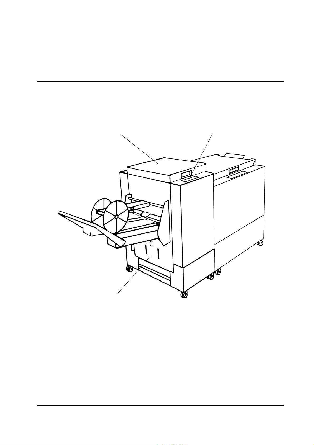
2.1 Main components
12
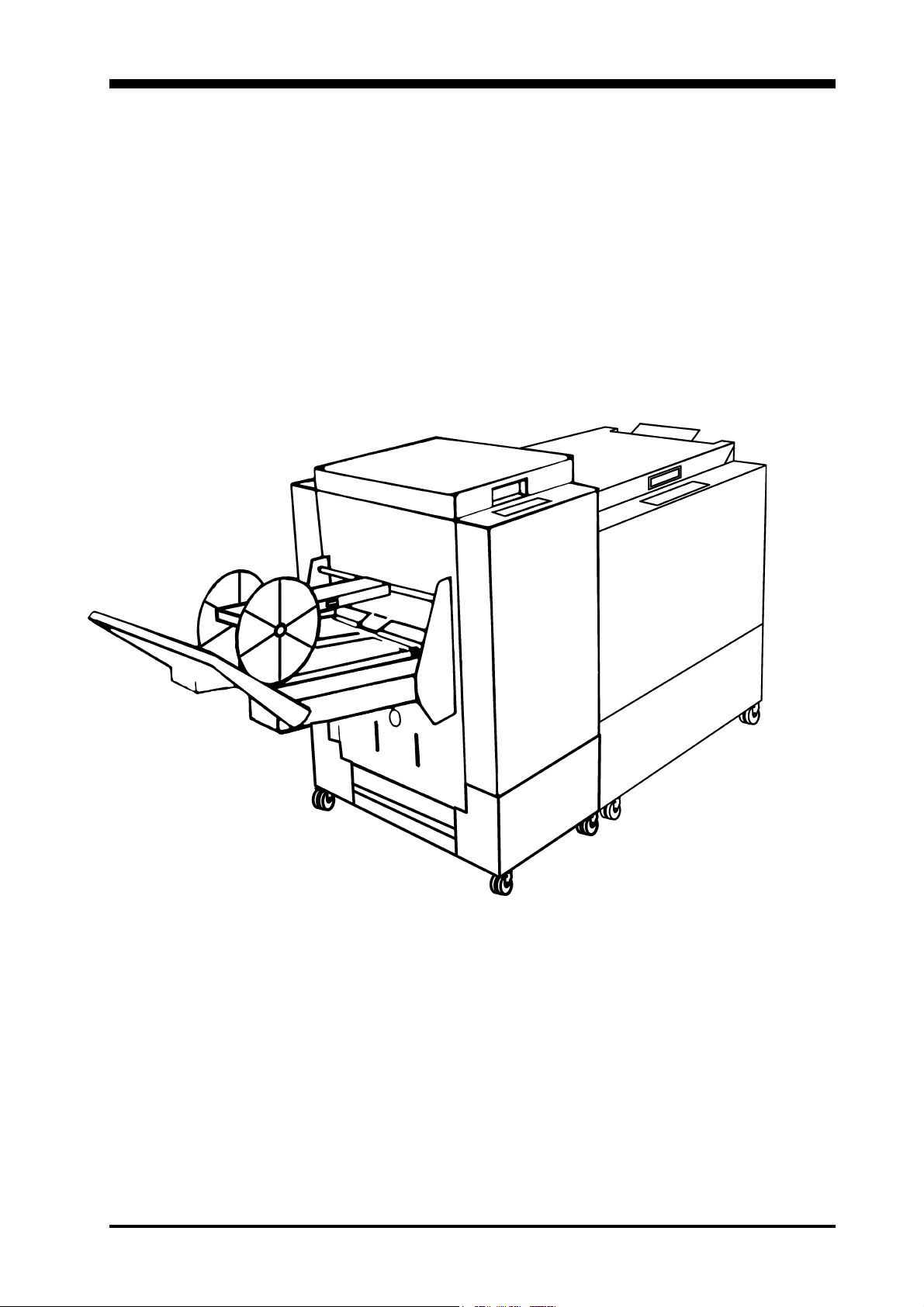
2. Getting to know the TR 85
Take a few minutes to become familiar with the main
components of the TR 85.
3
1. Top cover
2. Control panel
3. Scrap paper bin
Trimmer TR 85 Operator Manual
TR85 Op Man August 2000
2-1
Page 5
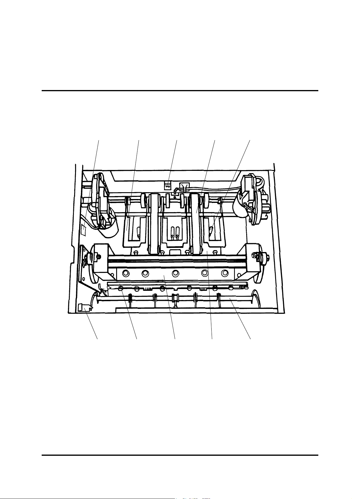
2.1 Main components, continues
The TR 85 interior has parts that you will come in contact with if paper jams occur.
12345
67 89 10
1 Total set counter 6 Infeed latch
2 Exit compressing brackets 7 Upper knife
3 Outfeed latch 8 Upper knife beam
4 Transport belt 9 Deck plate
5 Trimmer stop 10 Input roller shaft
Trimmer TR 85 Operator Manual
TR85 Op Man August 2000
2-2
Page 6

2.2 Control panel
12 3 4 5 67
8 9 10 11 12
1. Mode indicator LED
2. Trimmer mode
3. A3 / 17” size
4. 14” size (60Hz models)
5. Decreased cutting margin
6. Stacker full indicator
Trimmer TR 85 Operator Manual
7. Scrap paper bin full indicator
8. By-pass mode
9. A4 / 11” size
10. Increased cutting margin
11. Paper jam indicator
12. Dull knife indicator
2-3
TR85 Op Man August 2000
Page 7

3. Operator instruction
This chapter explains the operation of the TR 85 when
operating on-line with the SR 85.
3.1 Switching on the TR 85 power
1 Plug the SR 85 into the wall outlet.
2 Set ON/OFF switch (1) on SR 85 to ON position. The
TR 85 is automatically set to by-pass mode.
1
Trimmer TR 85 Operator Manual
TR85 Op Man August 2000
3-1
Page 8

3.2 Setting up the TR 85
The TR 85 has a pre-set cutting margin of 4mm when
selecting a paper size button on the operating panel. This
can be increased or decreased by pressing the adjustment buttons. The maximum cutting is 10mm.
Select a paper size
1 Press this button for A3/17" sheet size.
2 Press this button for A4/11" sheet size.
3 Press this button for 14" sheet size.
NOTE: Allow 10 seconds adjusting time
Select operating mode
4 Press this button for trimmer mode
5 Press this button for by-pass mode
NOTE: If a jam occurs in the TR 85, it will automatically
switch to by-pass mode. The control panel will however
still be indicating trimmer mode. When the jam is cleared
and top cover is closed, the TR 85 will return to trimmer
mode.
Trimmer TR 85 Operator Manual
TR85 Op Man August 2000
3-2
Page 9

3.3 Adjusting the cutting margin
The pre-set sizes are set for an approximately 4mm cut of
the middle sheet of the booklet. This can easily be adjusted by pressing the adjustment buttons to increase or
decrease the cutting margin. By pressing and holding the
button down the trimmer stop will move continuously, if
pulsing the button the trimmer stop will move for approximately 0,5mm.
Adjustments
1 Press this button to increase the trim
2 Press this button to decrease the trim
NOTE: Use the below table as a reference when setting the
cutting margin.
Number of sheets per booklet Amount of trim Adjustment procedure
2 through 5 sheets. 4 mm.
6 through 10 sheets. 5 mm.
11 through 15 sheets. 6 mm.
16 through 20 sheets. 7 mm.
Default setting is 4 mm. No
adjustment required.
Press the adjustment button two
times to increase the trim.
Press the adjustment button four
times to increase the trim.
Press the adjustment button four
times to increase the trim.
Trimmer TR 85 Operator Manual
TR85 Op Man August 2000
3-3
Page 10

3.4 Status indicators
When a status indicator comes on it does not usually
require a service call. After the condition is corrected, you
may continue production.
Indicators
1 Scrap paper bin full. Empty scrap paper bin.
2 Belt stacker full. Empty belt stacker.
3 A paper jam has occurred in the trimmer paper path.
See section 4 Problem solving for reference.
4 The trimmer knife has taken too long to complete the
trimming cycle. Open and close the top cover. If the indicator light stays on, call your service representative for
service.
Trimmer TR 85 Operator Manual
TR85 Op Man August 2000
3-4
Page 11

4.1 Clearing jams
4. Problem solving
This chapter explains how to clear a jam that may occur
during the operation of the TR 85. After clearing a jam,
close the top cover and continue the production.
The upper trimmer blade on the TR 85 is protected by a
knife protection plate that moves away during the cutting
stroke. Jams can occur in the input area or the exit area.
Input area jam clearance
1 Lift up the input roller shaft (1).
2 Remove the jam in the input area.
3 After the jam is removed, lift up the latch (2) and place
the input roller shaft into operating position.
1
2
Trimmer TR 85 Operator Manual
TR85 Op Man August 2000
4-1
Page 12

4.1 Clearing jams, continues
Exit area jam clearance
4 Lift the exit compressing brackets (3).
5 Secure them under the latch (4).
6 Remove the jam from the exit area.
7 After the jam is removed, lift up the latch (4) and place
the compressing brackets in operating position.
3
5
Trimmer TR 85 Operator Manual
TR85 Op Man August 2000
4-2
Page 13

4.2 Troubleshooting table
Use the below table as reference to solve problems that
may occur when operating the TR 85.
MELBORPESUACELBISSOPNOITCA
fotuognimocerasparcsdemmirT
tlebehtotnodna58RTeht
.rekcats
nosyatsrotacidninibrepapparcS
.deitpmeneebsahnibretfa
retfanosyatsthgilrotacidnimajehT
.deraelcsimaj
sithgilrotacidniefinkremmirtehT
.no
.llamsoothtdiwmirT.gnimmirtehtesaercnI
.etuhcrepap
niebyamtfahsrellortupniehT
.noitisopecneraelcreppu
gnisserpmocdnarellortixeehT
.noitisop
.kcihtotebyamtelkoobehTtonseodtelkoobehttahtkcehC
nithguacebyameceipdemmirtA
.noitisop
ecnaraelcreppuniebyamstekcarb
.etuhcrepapmorfeceipevomeR
hctaltfahsrellortupniehtesaeleR
gnitareponitfahsehtecalpdna
gnisserpmoctixeehtesaeleR
nimehtecalpdnahctalstekcarb
.noitisopgnitarepo
fosteehs02nahteromniatnoc
.repap)sbl02(msg08
Trimmer TR 85 Operator Manual
TR85 Op Man August 2000
4-3
Page 14

5.1 Specifications
5. Specifications
Trimmer TR 85
Trimmer TR 85 Operator Manual
TR85 Op Man August 2000
5-1
 Loading...