

Page 1
Service Manual
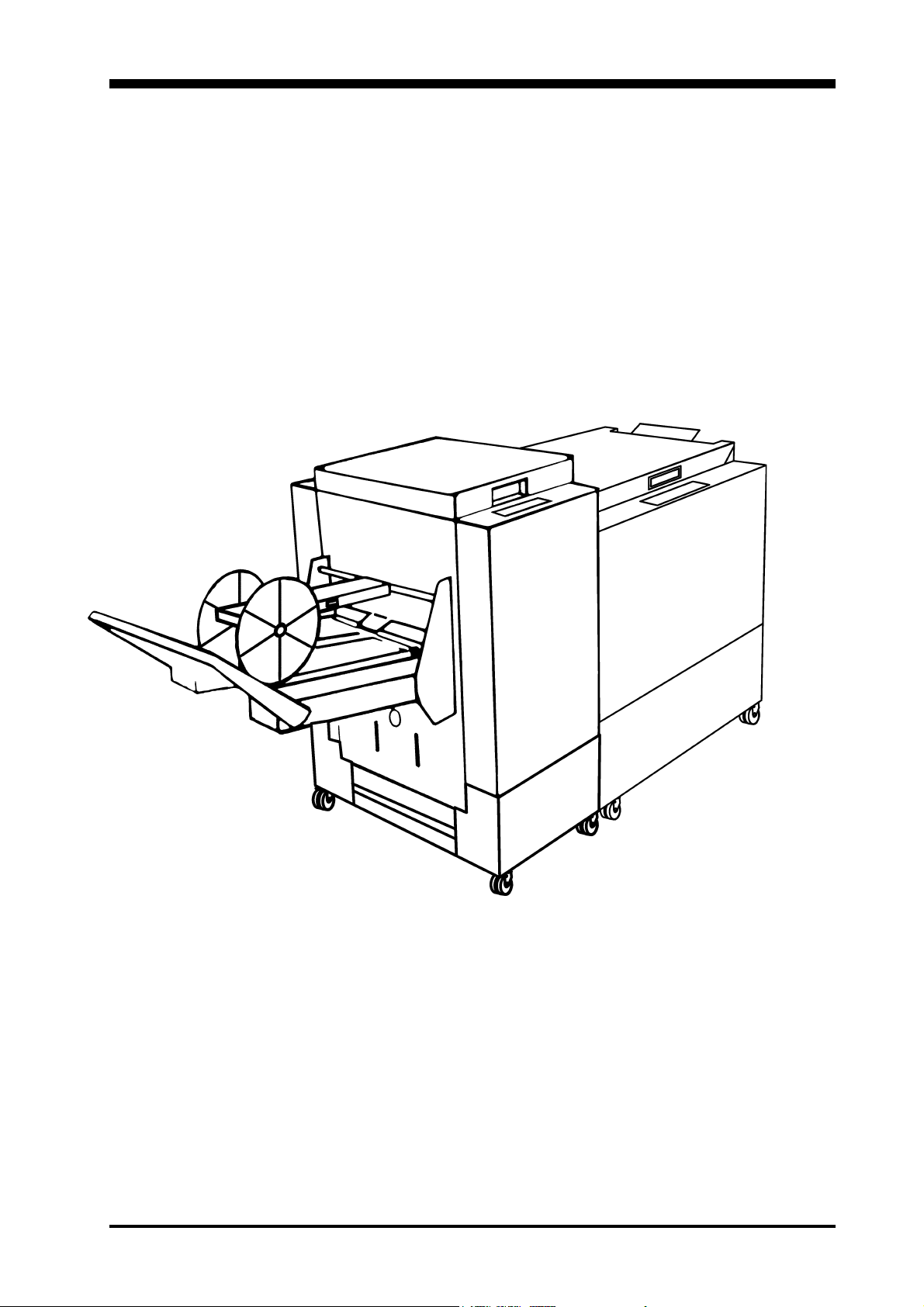
Trimmer TR 85
August 2000
Part No. 89004
Page 2

Contents
REPAIRS/ADJUSTMENTS (REP) PAGE
REP 3.1 Front cover 3.1.1
REP 3.2 Rear cover 3.2.1
REP 3.3 Upper cover, outfeed side 3.3.1
REP 3.4 Lower cover, outfeed side 3.4.1
REP 3.5 Protective cover 3.5.1
REP 3.6 Deck plate 3.6.1
REP 3.7 Stop carriage 3.7.1
REP 3.8 Exchanging PCB 3.8.1
REP 3.9 Front panel 3.9.1
REP 3.10 Knife motor (MOT1) 3.10.1
REP 3.11 Transmission motor (MOT2) 3.11.1
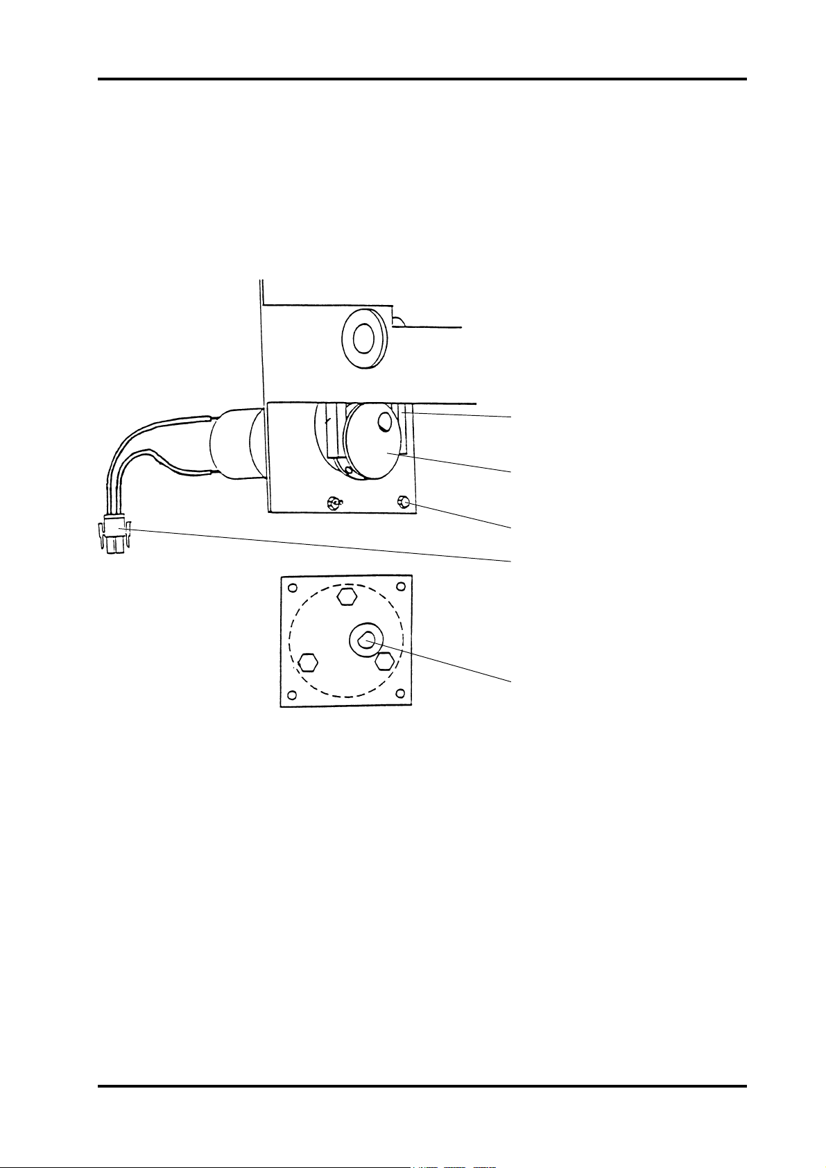
REP 3.12 Adjustment motor (MOT3) 3.12.1
REP 3.13 Trimmer stop motor (MOT4) 3.13.1
REP 3.14 Infeed switch (SW1) 3.14.1
REP 3.15 Control switch infeed, upper shaft (SW2) 3.15.1
REP 3.16 Stop carriage switch, lower position (SW4) 3.16.1
REP 3.17 Stop carriage switch, upper position (SW5) 3.17.1
REP 3.18 Interlock switch (SW6&7) 3.18.1
REP 3.19 Control switch, outfeed (SW8) 3.19.1
REP 3.20 Start switch (SOS10) 3.20.1
REP 3.21 Outfeed LED and sensor (LED1&PT1) 3.21.1
REP 3.22 Scrap paper bin LED (LED2) 3.22.1
REP 3.23 Scrap paper bin sensor (PR1) 3.23.1
REP 3.24 Knife 3.24.1
REP 3.25 Infeed shaft 3.25.1
REP 3.26 Lower outfeed belts 3.26.1
REP 3.27 Upper outfeed belts 3.27.1
REP 3.28 Transmission chain 3.28.1
REP 3.29 Knife support chain 3.29.1
REP 3.30 Knife chain 3.30.1
ELECTRONIC DETAIL INFORMATION
EDI 3.31 Test points 3.31.1
EDI 3.32 Wiring diagram 3.32.1
FAULT ISOLATING PROCEDURE
FIP 3.33 Fault isolating procedure 3.33.1
PREVENTIVE MAINTENANCE
MAI 3.34 Preventive maintenace 3.34.1
Trimmer TR 85 PAGE August 2000
Page 3
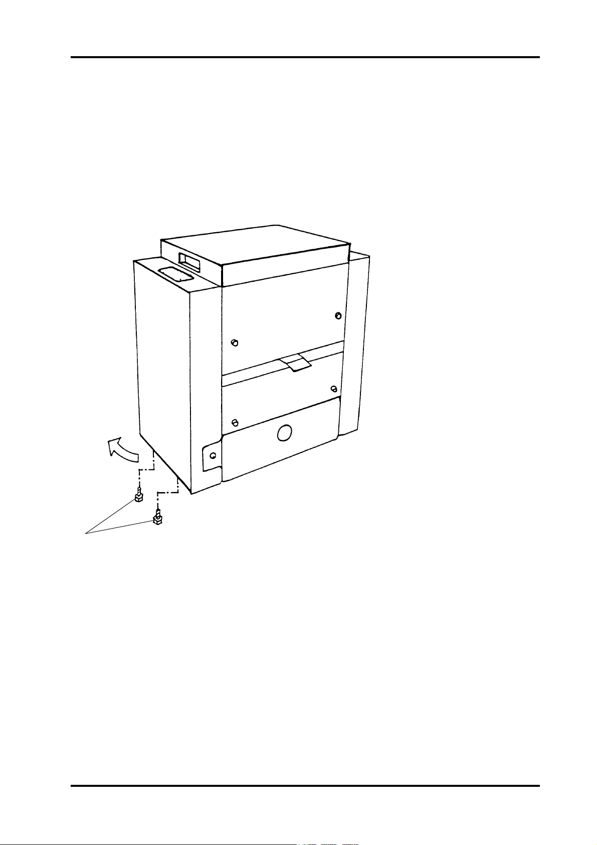
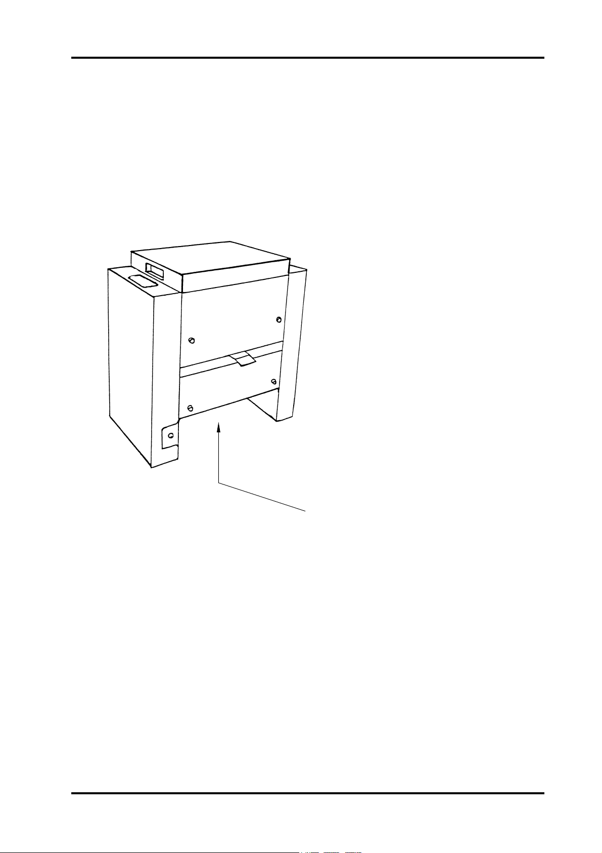
REP 3.1 Front cover
REMOVAL
1. Switch off the main power switch and disconnect the power cord.
2. Loosen the two screws (1).
3. Pull the lower side out as indicated in drawing and lift off the cover.
4. Disconnect the ground lead.
1
INSTALLATION / ADJUSTMENT
INSTALLATION
Installation is an exact reversed procedure of removal.
WARNING: Aviod direct light on SOS sensors. It may cause knife motor to start when
power is on. Make sure that ground wire is connected.
Trimmer TR 85 PAGE August 2000
3.1.1
Page 4
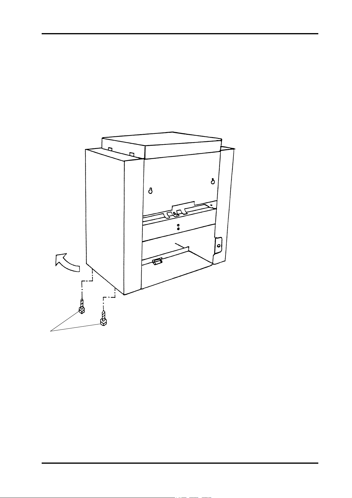
REP 3.2 Rear cover
REMOVAL
1. Switch off the main power switch and disconnect the main power cord.
2. Loosen the two screws (1).
3. Pull the lower side out as indicated in drawing and lift off the cover.
4. Disconnect the ground lead.
1
INSTALLATION / ADJUSTMENT
INSTALLATION
Installation is an exact reversed procedure of removal.
WARNING: Make sure ground wire is connected.
Trimmer TR 85 PAGE August 2000
3.2.1
Page 5

REP 3.3 Upper cover, outfeed side
REMOVAL
1. Switch off the main power switch and disconnect the power cord.
2. Remove front and rear cover according to REP 3.1 & 3.2.
3. Open top cover.
4. Remove interlock switches according to REP 3.18 and remove tie-wrap from cover.
5. Remove spring (1) holding compressing brackets.
6. Remove self-tapping screws (8 pcs).
7. Disconnect out feed sensor and remove tie-wraps holding cable.
8. Remove upper cover (2).
1
INSTALLATION / ADJUSTMENT
INSTALLATION
1. Connect out feed sensor according to REP 3.21.
2. Mount upper cover.
3. Switch on main power and check voltage on exit sensor according to REP3.21.
4. If sensor is exceeding values, adjust by slightly bending bracket on upper cover.
5. Check interlock function according to REP 3.18.
2
Trimmer TR 85 PAGE August 2000
3.3.1
Page 6
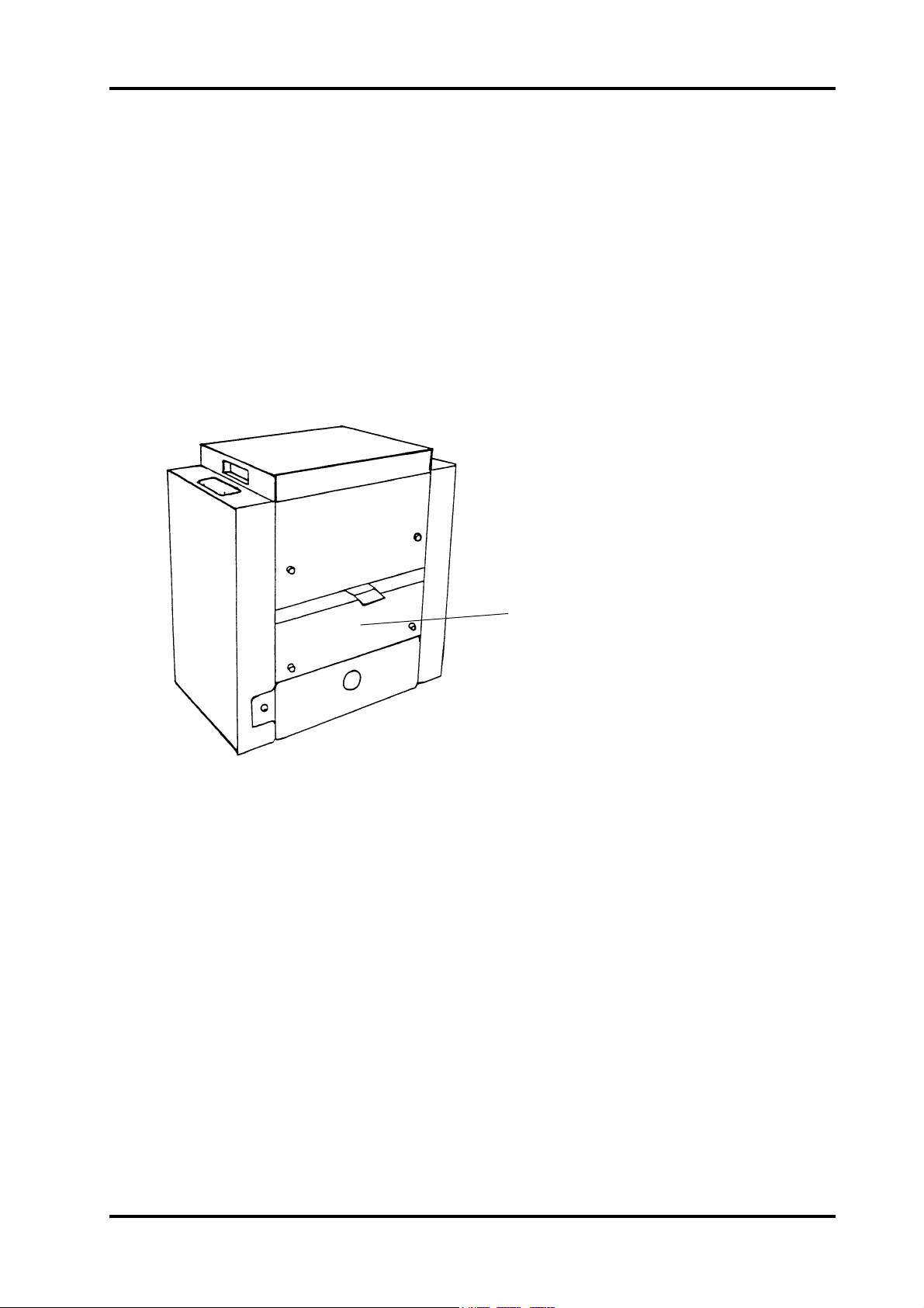
REP 3.4 Lower cover, outfeed side
REMOVAL
1. Switch off the main power switch and disconnect the power cord.
2. Remove belt stacker.
3. Remove front and rear cover according to REP 3.1 & 3.2.
4. Remove scrap paper bin.
5. Loosen the four screws holding deck plate to cover.
6. Remove the two screws holding protective cover to lower cover.
7. Remove the four screws holding cover to side frames.
8. Remove cover (1).
1
INSTALLATION / ADJUSTMENT
INSTALLATION
Installation is an exact reversed procedure of removal.
Trimmer TR 85 PAGE August 2000
3.4.1
Page 7
REP 3.5 Protective cover
REMOVAL
1. Switch off the main power witch and disconnect the power cord.
2. Remove scrap paper bin.
3. Remove the four screws holding protective cover to lower cover out feed side.
4. Loosen the four screws (10mm wrench) holding protective cover to lower knife beam
one turn (do not remove screws).
5. Pull protective cover (1) in out feed direction and remove cover.
1
INSTALLATION /ADJUSTMENT
INSTALLATION
Installation is an exact reversed procedure of removal.
CAUTION: Make sure cover is clear from harnesses when mounting cover.
Trimmer TR 85 PAGE August 2000
3.5.1
Page 8
REP 3.6 Deck plate
REMOVAL
1. Switch off the main power switch and disconnect the power cord.
2. Open top cover.
3. Move out feed compressing bracket to upper position.
4. Remove screws (1).
5. Remove the six screws holding deck plate to lower cover, out feed side (REP 3.4).
6. Remove deck plate through out feed opening.
1
INSTALLATION / ADJUSTMENT
INSTALLATION
Align support rollers on deck plate when mounted.
When compressing foam rollers manually, support rollers should rise 1mm.
CAUTION: Avoid damaging support rollers when deck plate is removed.
Trimmer TR 85 PAGE August 2000
3.6.1
Page 9
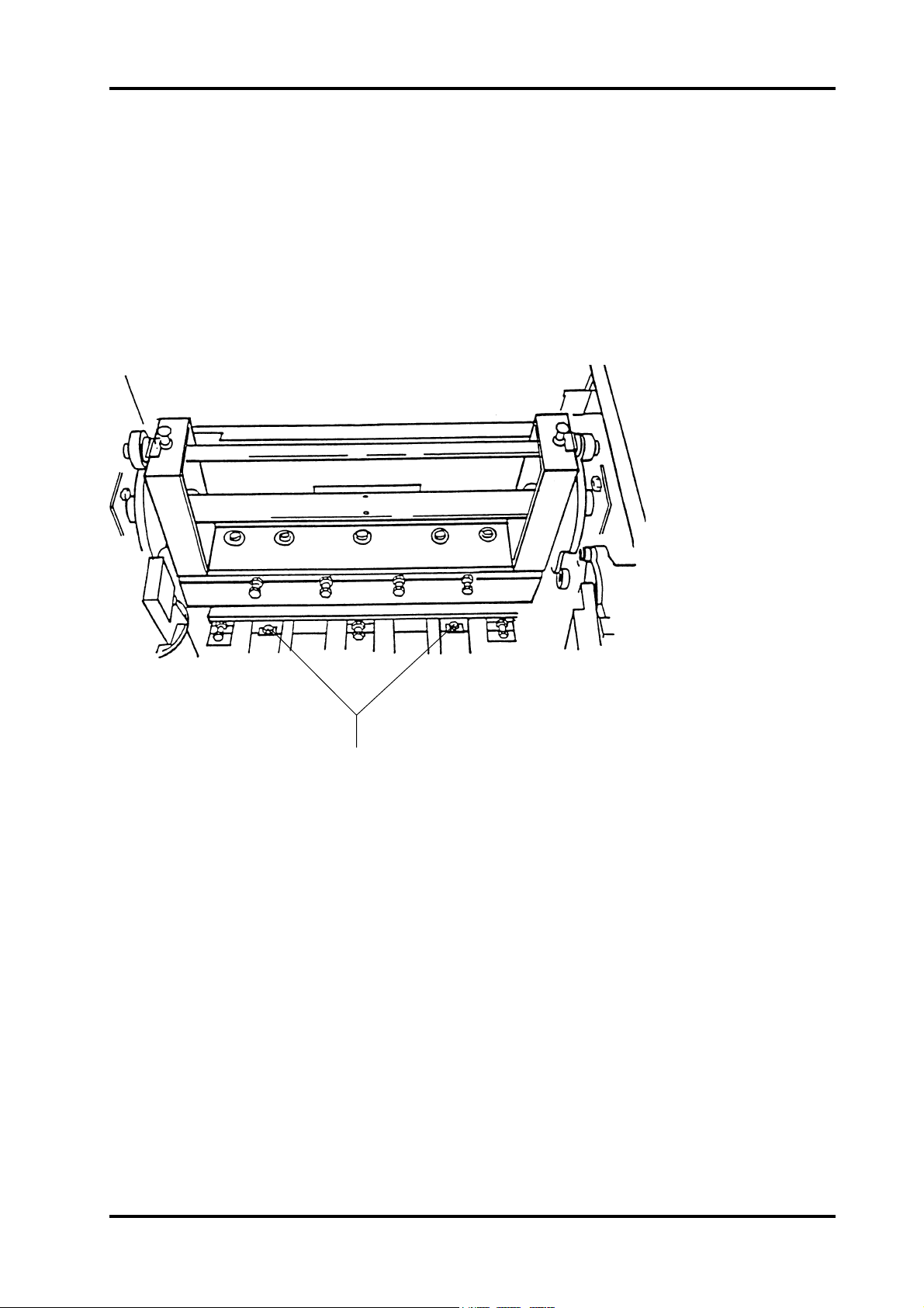
REP 3.7 Stop carriage
REMOVAL
1. Position the stop carriage in between A3 and A4 position, adjust on front panel.
2. Switch off the main power and disconnect the power cord..
3. Remove the scrap paper bin.
4. Remove front and rear cover acc. to REP 3.1 and 3.2.
5. Remove the protective cover acc. to REP 3.5.
6. Remove the lower out feed cover acc. to REP 3.4.
7. Disconnect the two connectors (1) from the side frame (not shown in figure).
8. Remove the stop carriage assy. By pulling on the plate (2).
2
1
INSTALLATION /ADJUSTMENT
Installation is an exact reversed procedure of removal.
CAUTION: When removing the stop carriage, stay clear from the SOS switches on the
circuit board.
Trimmer TR 85 PAGE August 2000
3.7.1
Page 10
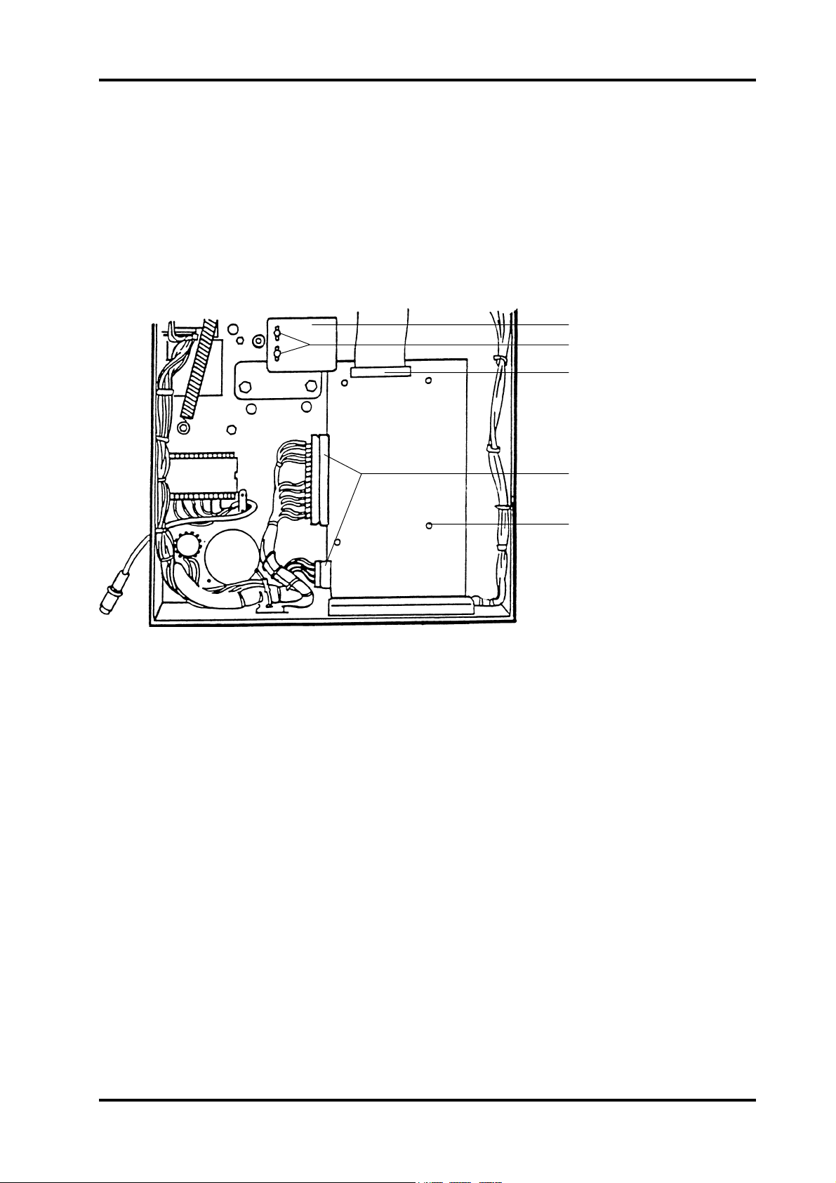
REP 3.8 Exchanging PCB
REMOVAL
1. Switch off the main power switch and disconnect the power cord.
2. Remove rear cover according to REP 3.2.
3. Disconnect front panel extension at PCB connector (1).
4. Remove the two nuts and washers (2) and remove the knife position indicator (3).
5. Disconnect the two connectors (4).
6. Remove the four nuts (5) and remove the PCB.
3
2
1
4
5
INSTALLATION / ADJUSTMENT
INSTALLATION
1. Mount PCB on to screws.
2. Connect harness and panel connectors.
3. Mount knife position indicator.
4. Make sure that top end of indicator is positioned flush to upper end of upper knife
position SOS, when knife is in top position.
Trimmer TR 85 PAGE August 2000
3.8.1
Page 11
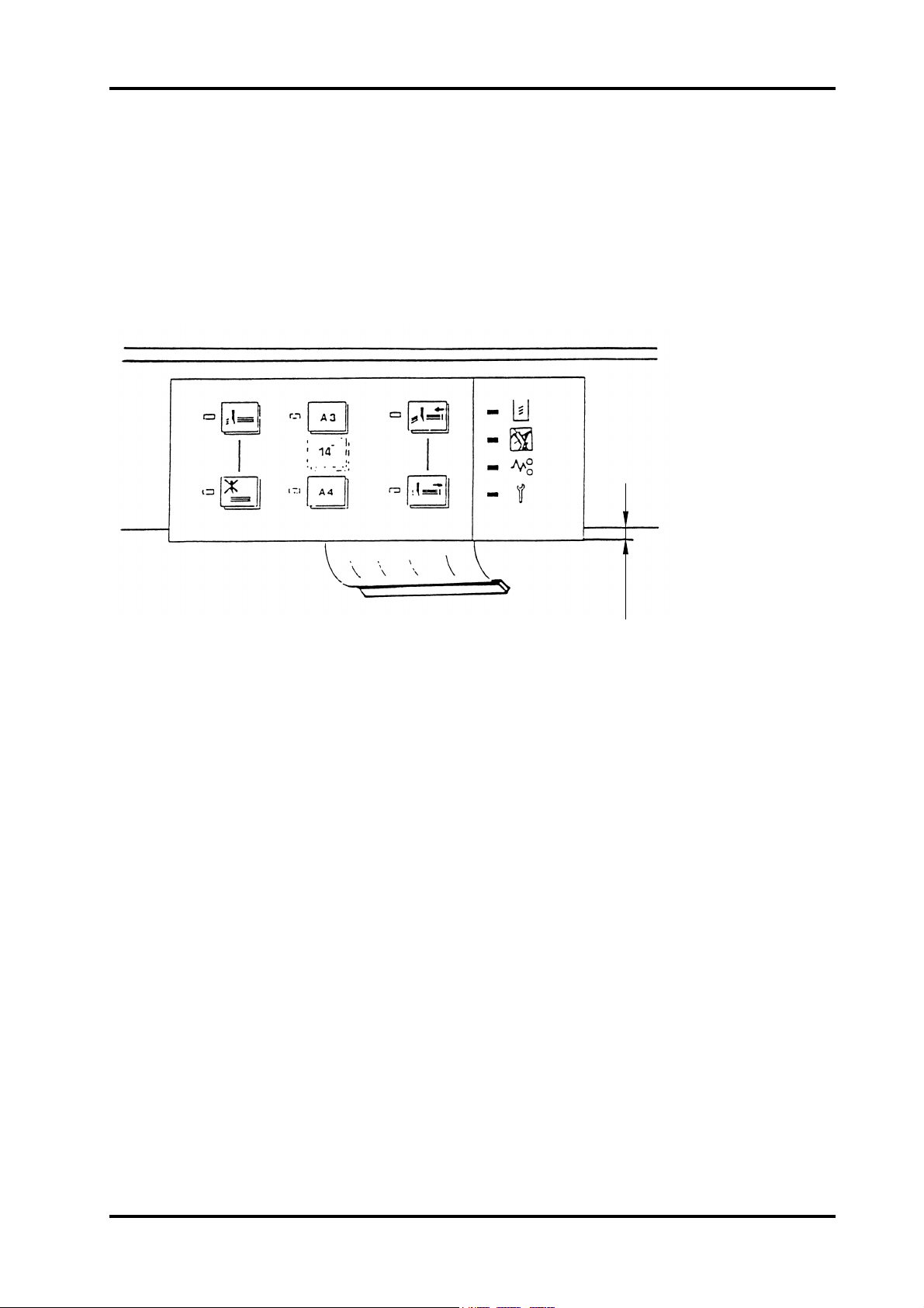
REP 3.9 Front panel
REMOVAL
1. Switch off the main power and remove the power cord.
2. Remove front cover according to REP 3.1.
3. Disconnect the panel from the adaptor board.
4. Remove the old panel, the panel is mounted with self-adhesive tape. (When tearing off,
the panel will be damaged.)
3 mm
INSTALLATION / ADJUSTMENT
INSTALLATION
1. Clean top surface of side frame with alcohol cleaner and remove protective film on
back of new panel.
2. Place the panel cantered sideways (80mm from edges) and 3mm off the edge according to figure above.
3. Connect the panel to adaptor board.
Trimmer TR 85 PAGE August 2000
3.9.1
Page 12
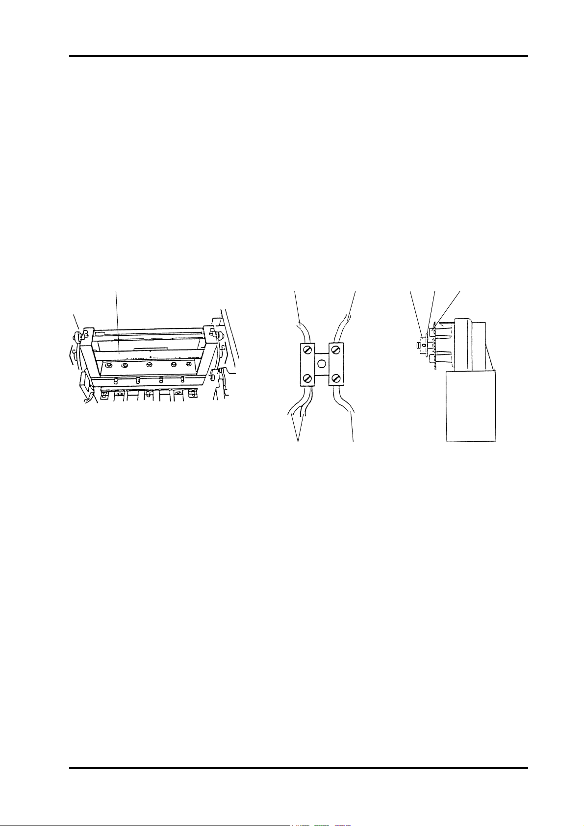
REP 3.10 Knife motor (MOT1)
REMOVAL
1. Switch off the main power and remove the power cord.
2. Remove rear cover according to REP 3.2.
3. Disconnect the wires from the motor at the terminal block (positioned on side of frame).
4. Use a 13 mm wrench to turn camshaft (1) clockwise until the knife is in lower position.
5. Remove knife chain according to REP 3.30.
6. Remove the sprocket (2) by loosening the two setscrews holding the sprocket to the
motor shaft and pull off the sprocket.
7. Remove the three screws (3) and lift out the motor.
1234
INSTALLATION / ADJUSTMENT
BLK RED
VIO
BRN
BLK
PURPOSE
The purpose is to ensure correct drive to the camshaft without any slack in the drive chain.
ADJUSTMENT
1. Mount the motor to the side frame, without tightening the screws, and connect the wires
to the terminal block according to figure.
2. Mount the sprocket (2) all the way into the clamp ring (4) and tighten the setscrews.
One of the sets screws have to be in the key-way of the shaft.
3. Tension the knife chain by moving the motor (5) and tighten the screws (3). There
should be NO slack in the knife chain.
WARNING: Stay clear from knife edge when turning camshaft and disengaging drive
chain.
Trimmer TR 85 PAGE August 2000
3.10.1
Page 13
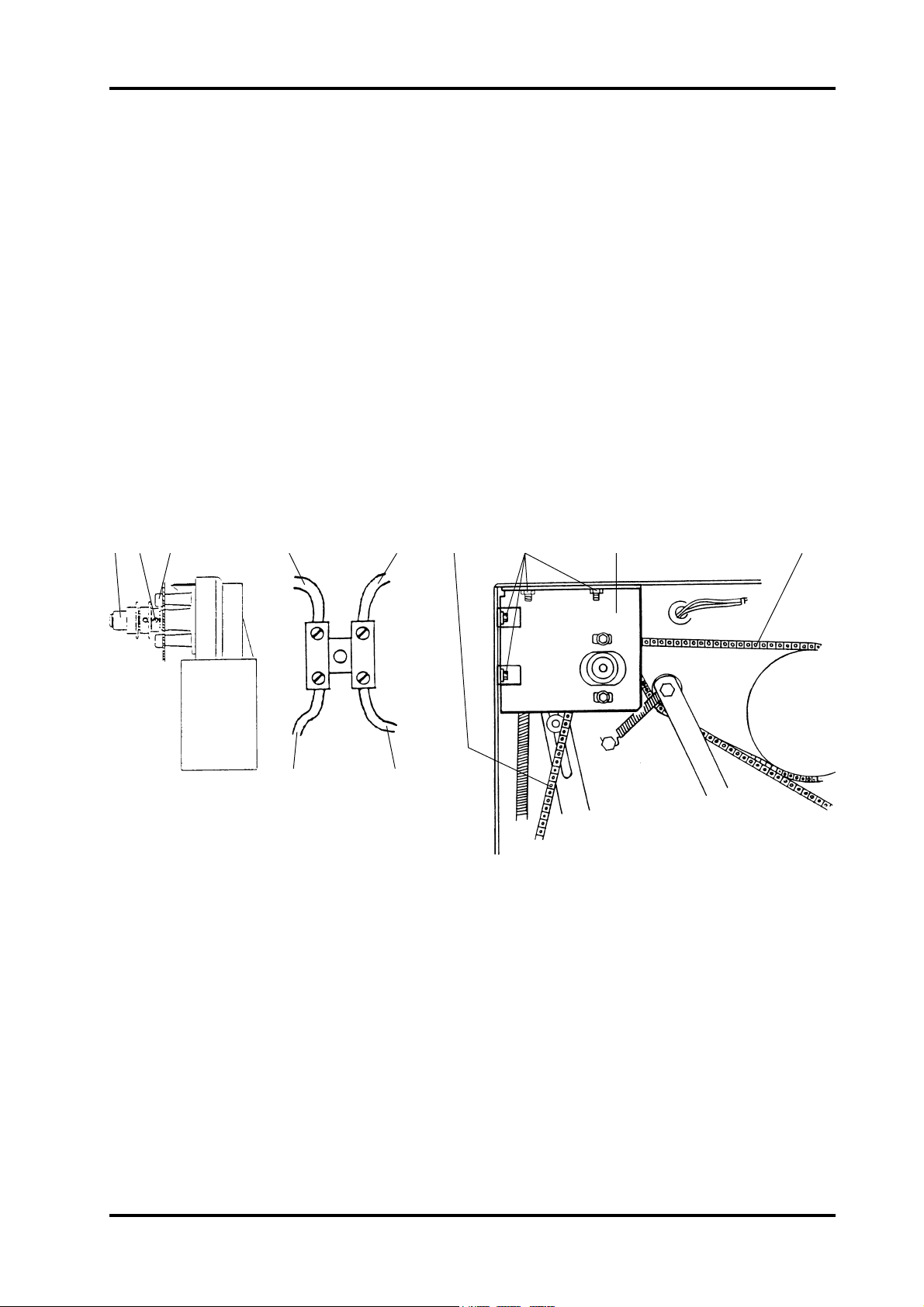
REP 3.11 Transmission motor (MOT2)
The main function on MOT 2 is main drive for feed belts.
By alter the polarity the reverse direction will function as a support motor for MOT 1
During the lower part of the cutting stroke.
REMOVAL
1. Switch off the main power and remove the power cord.
2. Remove front cover according to REP 3.1.
3. Disconnect the wires from the motor at the terminal block (fig. 2) positioned on side of
frame.
4. Remove the four screws (6).
5. Remove the support plate (7) by pulling it off the shaft assy (2).
6. Remove the transmission chain and knife support chain according to REP 3.28 and
3.29.
7. Remove the shaft assy (2) by pulling it out. The shaft assy is mounted with a wedge.
(Note the shim washers location when removing the shaft.)
8. Remove the three screws (3) and lift out the motor.
123 456 7
FIGURE 1 FIGURE 3FIGURE 2
INSTALLATION / ADJUSTMENT
PURPOSE
The purpose is to endure the correct drive without any slack in drive chains.
BLK
BLU
RED
WHT
ADJUSTMENT
1. Mount the motor to the side frame without tightening the screws (3).
2. Place the shim washer on to the motor shaft.
3. Mount the shaft assy (1) all the way into the motor hub.
4. Mount the knife support chain (4) according to fig. 3.
5. Tension the chain (4) by moving the motor and tighten the screws (3).
6. Mount the transmission chain (5) according to REP 3.28.
7. Mount the support plate (7). The bushing in the support plate can be adjusted up/down
for alignment.
8. Connect wires from motor according to fig.2.
Trimmer TR 85 PAGE August 2000
3.11.1
Page 14
REP 3.12 Adjustment motor (MOT3)
REMOVAL
1. Switch off main power and remove the power cord.
2. Remove the stop carriage according to REP 3.7.
3. Remove the return spring (2).
4. Disconnect the connector (1).
5. Loosen the four nuts (3) and remove the motor. (The motor is fitted into keyholes.)
123
INSTALLATION/ADJUSTMENT
Installation is an exact reversed procedure of removal.
CAUTION: When installing, make sure that the wires from the motor stays clear from
SOS switches when moving the carriage.
Trimmer TR 85 PAGE August 2000
3.12.1
Page 15
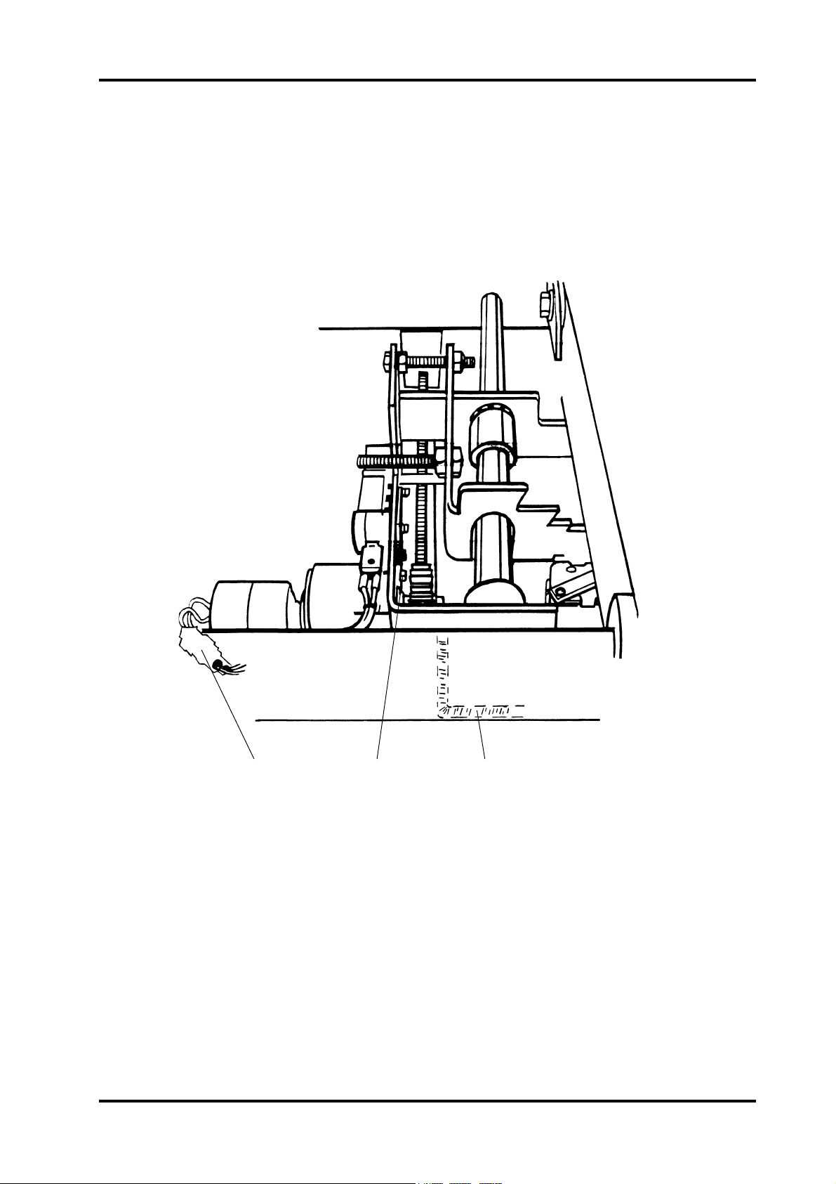
REP 3.13 Trimmer stop motor (MOT4)
REMOVAL
1. Switch off the main power and disconnect the power cord.
2. Remove the stop carriage according to REP 3.7.
3. Remove tie-wrap and disconnect the connector (1).
4. Loosen the four nuts (2) and remove the motor while lifting the plastic guide (3) off the
scored pulley (4).
3
4
2
1
5
INSTALLATION/ADJUSTMENT
PURPOSE
The purpose is to ensure that he pulley moves freely in the plastic guide.
ADJUSTMENT
1. Place the shaft (5) according to figure when mounting motor.
2. Align the pulley with the plastic guide and tighten the setscrew on to the cut out part of
the shaft.
NOTE: Motor is fitted into keyholes.
Trimmer TR 85 PAGE August 2000
3.13.1
Page 16

REP 3.14 Infeed switch (SW1)
The function of the switch is to set a control time to check if the books are too long for the
adjusted cutting margin or is miss folded.
REMOVAL
1. Switch off the main power and remove the power cord.
2. Open top cover.
3. Remove scrap paper bin.
4. Remove protective cover according to REP 3.5.
5. Disconnect the connector (1).
6. Loosen the two 7mm nuts (2) holding the switch bracket (3).
7. Lift out switch bracket (3) and remove the switch.
23 1
INSTALLATION/ADJUSTMENT
ADJUSTMENT
The switch should activate when inserting one 80gsm offset paper.
Check that no part of the switch is over the paper path when switcharm is in fully down
position. Check that the switch arm does not touch the wheel on in feed shaft when not
activated.
Trimmer TR 85 PAGE August 2000
3.14.1
Page 17

REP 3.15 Control switch infeed, upper shaft (SW2)
REMOVAL
1. Switch off the main power and disconnect the power cord.
2. Remove rear cover according to REP 3.2.
3. Disconnect the wires from the switch.
4. Remove the two screws (1) and lift out the switch.
1
INSTALLATION/ADJUSTMENT
ADJUSTMENT
1. The micro switch should trip when roller is 1-3mm above lower position (measured
while closing).
2. Connect the wires according to the drawing.
Trimmer TR 85 PAGE August 2000
3.15.1
Page 18

REP 3.16 Stop carriage switch, lower position (SW4)
REMOVAL
1. Switch off the main power and remove the power cord.
2. Remove the stop carriage according to REP 3.7.
3. Disconnect the wires from the switch.
4. Remove the two screws (1).
1
VIO
BLK
2-3 mm
INSTALLATION/ADJUSTMENT
ADJUSTMENT
1. The micro switch should activate when the stop fork is 2-3mm from the stop carriage
plate (2) according to fig. 2.
2. Connect the wires according to fig. 2.
Trimmer TR 85 PAGE August 2000
3.16.1
Page 19

REP 3.17 Stop carriage switch, upper position (SW5)
REMOVAL
1. Switch off the machine and disconnect the power cord.
2. Remove the stop carriage according to REP 3.7.
3. Disconnect the two wires from the switch.
4. Remove the screws (1).
12BLK GRN
INSTALLATION/ADJUSTMENT
PURPOSE
The purpose is to ensure correct position of the trimmer stop.
ADJUSTMENT
1. The micro switch should activate just before top position of the trimmer stop (2).
2. Connect the wires according to figure.
Trimmer TR 85 PAGE August 2000
3.17.1
Page 20

REP 3.18 Interlock switch (SW6 & 7)
REMOVAL
1. Switch off the main power and remove the power cord.
2. Open top cover.
3. Loosen the two screws (1) and remove the interlock assy. The interlock assy. is fitted
into key holes on the inside of the upper cover, outfeed side.
4. Disconnect the wires.
1
2
INSTALLATION/ADJUSTMENT
ADJUSTMENT
1. Connect jumper wire (2) to the middle pins on both switches.
2. Connect the orange and red wire to the two lower pins.
3. Mount the interlock switches into the keyholes and tighten the screws (1).
4. Remove rear cover according to REP 3.2.
5. Check interlock function by measuring resistance between red and orange wire on
terminal block, mounted on side frame next to PWB. Value should be less than 0,5
ohms with top cover closed. There should be no connection when top cover is open.
NOTE: Make sure that service switch is in “off” position when checking interlock
switches.
Trimmer TR 85 PAGE August 2000
3.18.1
Page 21

REP 3.19 Control switch outfeed compressing bracket (SW8)
SW8 function is to unable running of the machine with the compressing bracket in
Upper position.
REMOVAL
1. Switch off the main power and disconnect the power cord.
2. Remove the rear cover according to REP 3.2 and open the top cover.
3. Disconnect the wires from the switch.
4. Remove the two screws (1) and lift out the switch and insulating plate.
BRN
WHT
INSTALLATION/ADJUSTMENT
ADJUSTMENT
1. The micro switch should activate when the middle compressing bracket is 2-8mm from
upper lock position.
2. Connect the wires according to figure above.
NOTE: Fit nut plate onto top screw while holding other end of nut plate. Then swing nut
plate to correct position and fit the other screw.
Trimmer TR 85 PAGE August 2000
3.19.1
Page 22

REP 3.20 Start switch (SOS10)
REMOVAL
1. Switch off the main power switch and disconnect the power cord.
2. Remove the stop carriage according to REP 3.7.
3. Note position of connectors and disconnect them.
4. Remove screws and washers (1) while holding SOS with a pair of pliers.
5. Lift out SOS between trimmer stop and stop carrier.
1
INSTALLATION/ADJUSTMENT
INSTALLATION
1. Note diode mark on top of SOS, before mounting.
2. Mount the SOS with the diode mark turned as indicated in the drawing.
3. Connect the SOS according to the drawing.
4. Remove rear cover according to REP3.2.
5. Connect power cord and switch on main power.
6. Connect a V-meter between TP3 on PCB PL89-1 and common, select DC voltage.
7. Press the switch activator manually until it is flush with the trimmer stop, the sensor is
now blocked, the value should be less than 1 volt.
8. With the optical path clear, the value should be more then 14 volt.
CAUTION: The pins on the SOS are fragile, do not use excessive force when mounting.
Trimmer TR 85 PAGE August 2000
3.20.1
Page 23

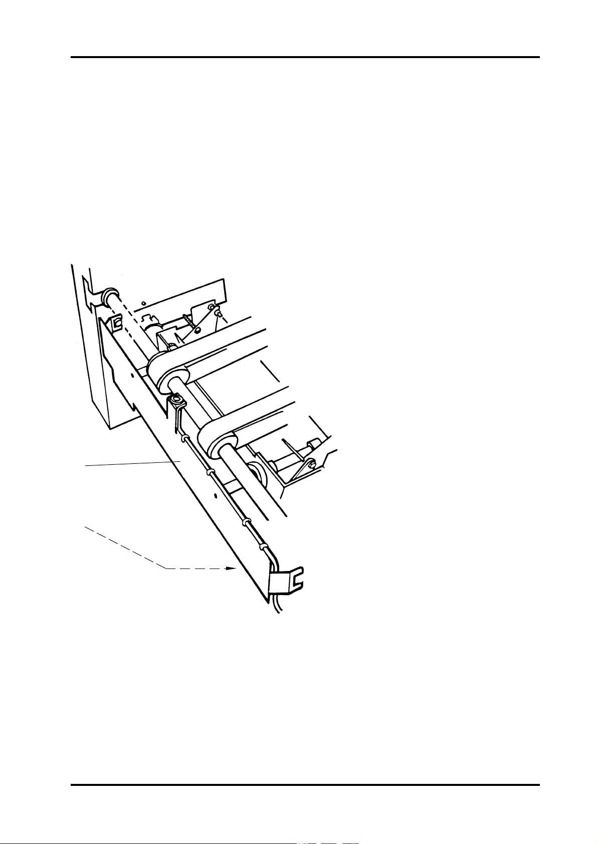
REP 3.21 Outfeed LED & sensor (LED1 & PT1)
REMOVAL
Switch off the main power and remove the power cord.
Remove sensor, fig. 1.
1. Pull the connector (1) off the pins from the sensor.
2. Remove the nut (2).
Remove LED, fig. 2.
1. Remove lower cover out feed according to REP 3.5.
2. Remove the stop carriage according to REP 3.8.
3. Pull the connectors off the pins from the LED (3).
4. Remove the nut (4).
BLK
(–)
1
2
INSTALLATION/ADJUSTMENT
4
5
3
BLK
(–)
PURPOSE
The purpose is to ensure that the correct output sensor voltage is obtained.
ADJUSTMENT
1. With the optical path from the LED to sensor clear, check that there is more than 10
VDC measured between TP4 on PCB PL89-1 and common. With the path blocked,
the voltage should be less than 1 VDC.
2. Move the sensor bracket (5) to obtain the correct voltage.
Trimmer TR 85 PAGE August 2000
3.21.1
Page 24

REP 3.22 Scrap paper bin LED (LED2)
REMOVAL
Switch off the main power and remove the power cord.
1. Remove scrap paper bin.
2. Pull the connector (1) off the pins from the LED.
3. Remove the 10mm nut and remove LED assy (2) from LED bracket (3).
12 3
INSTALLATION/ADJUSTMENT
PURPOSE
The purpose is to ensure that the correct sensor voltage is obtained.
ADJUSTMENT
1. Mount the LED assy in bracket.
2. Connect short pin on LED with blue wire on connector (ground).
3. Remove rear cover according to REP 3.2.
4. Connect the power cord and switch on the main power.
5. Connect a V-meter between TP6 and common on PCB PL89-1. the value should be
min. 8 VDC with the optical path to the sensor clear. With the light beam blocked, the
voltage should be max. 3.5 VDC. Adjust on trimmer TR1.
NOTE: Colours on wires can also be brown and black. Black is equal to blue.
WARNING: Avoid direct light on SOS sensors.
It may cause knife motor to start when power is on.
Trimmer TR 85 PAGE August 2000
3.22.1
Page 25

REP 3.23 Scrap paper bin sensor (PR1)
REMOVAL
1. Switch off the main power switch and disconnect the power cord.
2. Remove the scrap paper bin.
3. Pull the connector 1 off the pins of the photoreceiver.
4. Remove the photoreceiver assy by removing the two 6mm nuts located behind the
plate 2.
1
INSTALLATION/ADJUSTMENT
Installation is an exact reversed procedure of removal.
NOTE: After installing check adjustment of sensor according to REP 3.22.
Trimmer TR 85 PAGE August 2000
3.23.1
Page 26

REP 3.24 Knife
REMOVAL
1. Switch off the main power switch and disconnect the power cord.
2. Remove the belt stacker.
3. Lift off the TR85 from the SR85.
4. Lift the outfeed compressor assembly to upright position.
5. Remove the upper infeed cover.
6. Remove protective cover according to REP 3.5.
WARNING: Stay clear from upper knife. The knife edge may cause serious injuries. Use
the safety block (14) to put between lower knife and upper knife beam as
much of the time as possible throughout this REP.
Upper knife
7. Place the safety block (14) between lower knife and upper knife beam.
NOTE: The safety block is located inside the rear cover by the interlock bypass switch.
8. Remove knife protection plate (7) by removing the three screws (2).
9. Move transport protection from the new to the old knife or use the transport protection supplied in the Trimmer installation kit.
10. Release the set clamp by releasing the E-clip on the middle plunger.
11. Remove the six screws (4) with the cup spring washers.
NOTE: When removing screws the nuts (7) will fall down through the cut-out in bottom
of knife beam.
12. Lift out the upper knife.
Lower knife
7. Remove the four screws (11) in the middle
with the washers.
8. Remove the two screws (11) at each end of
the knife with cup spring washers.
9. Lift out the lower knife.
INSTALLATION
Upper knife
1. Move transport protection from the old to the
new knife.
2. Clean and apply grease on guide bars (6)
and side guides (3).
3. Fit knife onto guide bars.
Apply grease on the cup spring washers closest to the
knife.
Mount screws (4).
4. Remove transport protection and mount it on the old
knife.
5. Mount knife protection plate (7).
6. Mount the set clamp.
1
2
3
4
5
6
7
Upper knife Lower knife
8
9
10
Lower knife
1. Place the lower knife onto the lower knife beam.
2. Apply grease on all washers.
3. Mount the two screws (11) at each end of the knife with cup spring washers.
4. Mount the four screws (11) in the middle with the washers.
Trimmer TR 85 PAGE August 2000
3.24.1
Page 27

REP 3.24 Knife, continues
ADJUSTMENT
1. Turn the six mounting screws (4) so there is no tension and no play between cup spring
washers and upper knife.
Then turn the mounting screws (4) one revolution clockwise.
2. Loosen the nuts (9) and turn the three adjustment screws (10) fully counter clockwise.
Loosen the six mounting screws (11) on lower knife.
Push the lower knife against the bracket (8).
11
10 9 8
3. Use the safety block (14) to put between lower knife and upper knife beam as much of
the time as possible throughout this adjustment.
4. Use a feeler gauge and check that the space (12) between upper knife and the two red
marked screws in the middle (1) is 0.50 mm.
Adjust the space if necessary on the two outer adjustment screws and nuts (1).
FIGURE 1
1
4
0.50 mm
Trimmer TR 85 PAGE August 2000
3.24.2
12
Page 28

REP 3.24 Knife, continues
13
14
5. Lower the upper knife to the bottom position by turning crank shaft (13) using a 13 mm
wrench.
Caution: When bringing the upper knife down make sure it does not touch the lower
knife.
6. Push in the lower knife against the upper knife a couple of times on both ends to make
sure it is against the upper knife at the whole cutting area.
7. Raise the upper knife to the top position by turning crank shaft (13).
8. First tighten the screws (11) a little according to the sequence A-F Figure 1.
Then tighten a little harder to finally fully tighten the screws according to the sequence.
9. Turn the adjustment screws (10) so they touches the lower knife.
10. Slowly and carefully without paper lower the upper knife to the bottom position by turning crank shaft (13). If the upper knife touches the lower knife, back up the upper knife
and start over from step 2.
NOTE: Look through the cut out in the side frame while turning crank shaft.
11. Make a two sheet folded (or staple and folded) A3 (11“x17“) 80 gsm set and place it in
cutting position.
Trim the set by turning crank shaft (13).
NOTE: Use the SR85 to staple and fold the required sets.
12. If the set is not correctly cut on one of the ends, loosen the five mounting screws (11) on
that end and keep the one mounting screw tightened at the good end.
Turn the adjustment screw (10) on the bad end 1/36 revolution or 10°. See figure 2.
Repeat step 8 and 9, then return to this step until it cuts clean on the sets both ends.
13. Make a 15 sheet folded (or staple and folded) A3 (11“x17“) 80 gsm set
and place it in cutting position.
Trim the set by turning crank shaft (13).
Repeat step 12.
14. Make a 20 sheet folded (or staple and folded) A3 (11“x17“) 80 gsm
set
and place it in cutting position.
Trim the set by turning crank shaft (13).
Repeat step 12.
FIGURE 2
Trimmer TR 85 PAGE August 2000
3.24.3
Page 29

REP 3.24 Knife, continues
15. If the set is not correctly cut in the middle, loosen the four mounting screws (11) in the
middle and keep the mounting screws tightened at the ends.
Turn the adjustment screw (10) in the middle 1/36 revolution or 10°. See figure 2.
Repeat step 8 and 9, then return to this step until it cuts the set all clean on 20 folded
sheets.
NOTE: As guidance you can trim a 25 sheet set to clearer see if the result of the adjust-
ments are correct.
16. If the set is not correctly cut on one of the ends after step 15, loosen the adjustment
screw (10) in the middle and start over from step 12.
17. Tighten the lock nuts (9).
18. Return the machine to operational condition.
CAUTION: If the knife/knifes has been damaged, they have to be replaced or sharpened
even if a correct result is obtained because of shortened life time.
NOTE: When the upper knife becomes dull it is possible to sharpen it.
The upper knife can be sharpened until it is 70 mm wide at the shorter end.
70 mm
Trimmer TR 85 PAGE August 2000
3.24.4
Page 30

REP 3.25 Infeed shaft
If this action is due to old or broken o-rings, skip item 9-10.
If removing drive shaft sprocket is intended, do this before removing E-clip.
REMOVAL
1. Switch off main power switch and remove power cord.
2. Remove front and rear cover according to REP 3.1 and 3.2
3. Remove transmission chain (1) according to REP 3.28.
4. Remove springs (2) from infeed linkage (3) on both sides.
5. Remove screws holding compressing shaft (4) to infeed linkage.
6. Move all o-rings to front end of shafts and lift out compressing shaft.
7. Remove rear E-clip on drive shaft (5) and push shaft into bearing in rear side frame.
8. Remove o-rings from drive shaft.
9. Remove sprocket (6) from drive shaft and remove infeed linkage and washers.
10. Push/Pull rear bearing out of side frame and lift out shaft.
1
4
5
6
3
2
INSTALLATION/ADJUSTMENT
PURPOSE
The purpose is to ensure that the compressing shaft is aligned with paper path.
INSTALLATION
1. Fit shaft and rear bearing into side frame and fit o-rings on shafts.
2. Mount E-clip, washers, infeed linkage and sprocket on drive shaft.
3. Mount infeed linkage on compressing shaft, make sure that shaft is aligned with paper
path and tighten locknuts on screws.
4. Fit springs on screws and mount transmission chain.
Trimmer TR 85 PAGE August 20003.25.1
Page 31

REP 3.26 Lower outfeed belts
REMOVAL
1. Switch the TR85 to A3 (11”X17”) position.
2. Switch off the main power switch and disconnect the power cord.
3. Remove lower cover, outfeed side according to REP 3.4.
4. Open top cover and remove deck plate according to REP 3.6.
5. Remove transmission chain from lower out feed shaft according to REP 3.28.
6. Remove E-clip at rear side frame bearing on out feed shaft.
7. Loosen the two screws (1) holding the adjustable out feed shaft (2) to knife beam
brackets(3).
8. Push/pull out feed shaft out of bearing in front side frame.
9. Remove one of the screws holding the adjustable shaft and remove the lower out feed
belts (4).
12 34
INSTALLATION/ADJUSTMENT
PURPOSE
The purpose is to ensure correct out feed by equal tension of the out feed belts.
INSTALLATION
1. Fit belts on rollers.
2. Fit out feed shaft into bearing and mount E-clip and transmission chain.
3. Fit belts on rollers, tension belts and tighten screws on adjustable shaft.
4. Mount deck plate and lower out feed cover.
CAUTION: Avoid damaging the support rollers on deck plate when removed.
Trimmer TR 85 PAGE August 2000
3.26.1
Page 32

REP 3.27 Upper outfeed belts
REMOVAL
1. Switch off the main power switch and disconnect the power cord.
2. Remove belt stacker and remove front and rear cover according to REP 3.1 and 3.2.
3. Remove springs (7) and six of the screws holding upper out feed cover (top pair remains).
4. Open top cover and tilt upper out feed cover according to fig. 1.
5. Remove E-clip, spring bracket (1), plastic washers and needle bearings (2) from compressing shaft.
6. Remove E-clips (6) at outer compressing brackets and push/pull out shaft.
7. Remove transmission chain from sprocket on upper out feed shaft according to REP
3.32.
8. Remove E-clips next to bearing 839 in side frames and pull bearings out of side frame.
9. Remove out feed compressing assy.
10. Loosen the two screws (4) and remove the upper feed belts (5).
6
7
1
2
3
FIGURE 1 FIGURE 2
INSTALLATION/ADJUSTMENT
PURPOSE
The purpose is to ensure correct out feed by equal tension of the out feed belts.
5
4
5
6
INSTALLATION
1. Tension the out feed belts and tighten the screws.
2. Insert compressing assy into TR85, fit bearings into side frames and continue in reversed order compared to removal.
CAUTION: Avoid damaging the support rollers on deck plate when mounting compress-
ing assy.
Trimmer TR 85 PAGE August 2000
3.27.1
Page 33

REP 3.28 Transmission chain
REMOVAL
1. Switch off the main power and remove the power cord.
2. Remove front cover according to REP 3.1.
3. Lift off chain tensioner (1) from transmission chain (2).
4. Lift off chain from sprocket on upper out feed shaft.
5. Lift off chain from sprocket on lower out feed shaft.
6. Remove chain.
12
INSTALLATION/ADJUSTMENT
INSTALLATION
Install chain as in figure.
CAUTION: Make sure that chain lock is in right direction.
Trimmer TR 85 PAGE August 2000
3.28.1
Page 34

REP 3.29 Knife support chain
REMOVAL
1. Switch off the main power switch and remove the power cord.
2. Remove front cover according to REP 3.1.
3. Remove transmission chain according to REP 3.28.
4. Remove chain tension spring (1) and flip tensioner (2) over to crank shaft sprocket (3).
5. Loosen the three screws (4) holding MOT 2 1-2 turns and push the motor towards the
crankshaft.
6. Lift the knife support chain off the motor sprocket and remove chain.
4
5
1
2
3
INSTALLATION/ADJUSTMENT
INSTALLATION
1. Mount knife support chain on to crankshaft sprocket.
2. Mount chain on motor sprocket.
3. Tension the chain by moving the motor and tightening the screws.
4. Mount transmission chain according to REP 3.28.
CAUTION: Make sure that chain locks is in right direction. There should be no slack in
chain.
Trimmer TR 85 PAGE August 2000
3.29.1
Page 35

REP 3.30 Knife chain
REMOVAL
WARNING: Remove the safety block (1) from the interlock bypass bracket and place it
between the knife beams, or rotate the upper knife beam to the down position, to prevent
knife from falling.
1. Switch of the main power switch and remove the power cord.
2. Remove rear cover according to REP 3.2.
3. Disconnect front panel extension from front panel (2).
4. Loosen the three screws (3) holding knife motor 1-2 turns, and push motor towards the
crankshaft.
5. Lift the knife chain off the motor sprocket (4) and remove chain.
12345
INSTALLATION/ADJUSTMENT
INSTALLATION
1. Mount knife chain on to crankshaft sprocket (5).
2. Mount chain on motor sprocket.
3. Tension the chain by moving the motor and tightening the screws.
4. Remove safety block from knife beams and place it on the bypass bracket.
CAUTION: Make sure that the chain locks in its right direction. There should be no slack
in chain.
Trimmer TR 85 PAGE August 2000
3.30.1
Page 36

EDI 3.31 Test points
The test points can be used to verify components function.
Any common ground can be used as a negative connection.
Test points 1-6 are numbered from left to right.
Not activated Activated
TP1 Turning of stop carriage (SOS on PCB) 14-15 VDC <2 VDC
TP2 Exit sensor signal from SR85 >14 VDC
TP3 Signal from start sensor SOS 10 >14 VDC <1VDC
TP4 Out feed sensor LED1/PT1 >9 VDC
TP5 End position for stop carriage (SOS on PCB) 14-15 VDC <2VDC
TP6 Scrap bin sensor PR1 (Adjust on trimmer) 8.5-10 VDC
TP7 Knife home position sensor (SOS on PCB) 14-15 VDC <2VDC
TP8 Start of transmission motor (SOS on PCB) 14-15 VDC <2VDC
TP9 11”/A4 sensor (SOS on PCB) 14-15 VDC <2VDC
TP10 14” sensor (SOS on PCB) 14-15 VDC <2VDC
TP11 17”/A3 sensor (SOS on PCB) 14-15 VDC <2VDC
Trimmer TR 85 PAGE August 2000
3.31.1
Page 37

Page 38

FIP 3.33 Fault isolating procedure
GUIDELINES
The fault isolating procedure is showing the operating sequence of the trimmer from switching on for a
specific job to stacking of sets as a reference.
Follow the below guide to systematically locate information in the fault isolating procedure.
SEQUENCE OF OPERATION -Were in the operating sequence does the problem occur?
OBSERVED FAULT -What is the observed fault?
POSSIBLE CAUSE -What are the possible causes for the problem to occur?
FAULT ISOLATION/REPAIR -Guidelines and reference for corrective actions.
Trimmer TR 85 PAGE August 2000
3.33.1
Page 39

FIP 3.33 Fault isolating procedure
SEQUENCE OF OPERATION
Trimmer switched on.
OBSERVED FAULT
No machine initialisation.
Belts running continousely.
Trimmer knife cycling continousely.
POSSIBLE CAUSE
Secondary fuse in trimmer.
24 VDC supply to PCB 89-1.
Primary circuit from stapler
folder 220/115 Vollts.
Main PCB defective.
Phototransistor/LED in
stapler folder defective.
Start signal circuit stapler
folder to trimmer interrupted.
Main PCB defective.
Knife position indicator
misadjusted.
Knife home position
sensor defective.
FAULT/ISOLATING REPAIR
Located at the transformer
Check for 30 VDC at connector J1 pin
C12 and common ground on PCB 89-1.
Check voltage at power cord from
stapler folder.
Replace PCB 89-1 see REP 3.8.
Check test point TP2 on PCB 89-1 see
EDI 3.31.
Check connection of interface cable.
Replace PCB 89-1 see REP 3.8.
Adjust according to REP 3.8.
Check test point TP7 see EDI 3.31.
Main PCB defective.
Jam indication printer.
Trimmer TR 85 PAGE August 2000
Interlock switches on top
cover defective.
Interface cable not connected.
3.33.2
Replace PCB 89-1 see REP 3.8.
Replace/adjust SW6, SW7
see REP 3.18.
Connect interface cable.
Page 40

FIP 3.33 Fault isolating procedure
SEQUENCE OF OPERATION
Set up procedure.
Paper transport in stapler folder.
OBSERVED FAULT
Format setting inoperative.
Jam indication trimmer.
POSSIBLE CAUSE
PTC recistor on main PCB activated
(stop carriage has to activate and
reverse from end switch in two
seconds).
Insufficient connection on
stop carriage.
Slotted optical switches
on PCB defective.
Stop carriage motor MOT 3
defective.
Main PCB defective.
Control switch SW2 defective/
misadjusted.
Compressing brackets remaining in
upper jam/clearance position.
Control switch compressing brackets
SW8 defective/misadjusted.
FAULT/ISOLATING REPAIR
Switch off stapler folder for five seconds
M/C will regain operative mode when
switched on.
Check connection of stop carriage.
Check test points TP5,9,10 and 11
see EDI 3.31.
Check for app. 24 VDC at J1 pin C8 and
J1 pin C6.
Replace PCB 89-1 see REP 3.8.
Check according to REP 3.15.
Check compressing brackets.
Check according to REP 3.19.
Infeed switch SW1 defective/
misadjusted.
Trimmer TR 85 PAGE August 2000
3.33.3
Check according to REP 3.14.
Page 41

FIP 3.33 Fault isolating procedure
SEQUENCE OF OPERATION
Paper transport in stapler folder cont.
Infeed trimmer.
Set entering belt transport.
OBSERVED FAULT
Scrap paper bin full indication.
Belt, transport not running.
Skew cutting.
Position of cut variating.
POSSIBLE CAUSE
Scrap paper bin full.
LED2/PR1 defective/misadjusted.
Main PCB defective.
Photo transistor, outfeed stapler folder
defective.
Transmisssion motor MOT2
defective.
Main PCB defective.
Transmission defective.
Incorrect belt tension.
Incorrcet belt tension.
FAULT/ISOLATING REPAIR
Empty scrap paper bin.
Check voltage on PR1 see REP 3.22.
Replace PCB 89-1 see REP 3.8.
Check voltage on test point TP2 see EDI
3.31.
Check for 24 VDC on motor MOT2.
Check for 24 VDC on connector J2 pin 1
and 2 see EDI 3.32.
Check for loose hardware.
See REP 3.26 and 3.27 for adjustment.
See REP 3.26 and 3.27 for adjustment.
Incorrect position of stop carriage
switches.
Mechanical obstacles.
Incorrect position of cut.
Trimmer TR 85 PAGE August 2000
Incorrect position of stop carriage indicator.
Slotted optical switches defective.
3.33.4
See REP 3.16 and 3.17 for adjustment.
Grease, oil, burrs etc. on paper path.
Adjust indicator on stop carriage so that
the cutting margin is 4-5mm.
Check test points TP9-11 see EDI 3.31.
Page 42

FIP 3.33 Fault isolating procedure
SEQUENCE OF OPERATION
Set entering belt transport cont.
Set arrives at the trimmer stop.
OBSERVED FAULT
Incorrect position of cut cont.
Trimmer stop not in upper position.
Set does not activate start switch
SOS10.
No knife operation despite switch actuation.
POSSIBLE CAUSE
Main PCB defective.
Off-line mode selected on front panel.
Stop carriage switch SW5
defective.
Trimmer stop motor MOT4 defective.
Main PCB defective.
Low drive on infeed belts.
Mecanical obstacles.
Switch actuator misadjusted.
SOS10 defective.
Main PCB defective.
FAULT/ISOLATING REPAIR
Replace PCB 89-1 see REP 3.8.
Select trimme mode.
See REP 3.17 for repair.
Check for DC voltage on connector J1 pin
8A and common ground on PCB 89-1.
See REP 3.13 for repair.
Replace PCB 89-1 see REP 3.8.
Clean/tension infeed belts.
Grease, oil, burrs etc. on paper path.
Adjust according to REP 3.20.
Check/replace according to REP 3.20.
Check for 24 VDC at connector J2 pin 2
and common ground on PCB 89-1 / replace PCB 89-1 see REP 3.8.
Knife motor MOT1 defective.
Trimmer TR 85 PAGE August 2000
3.33.5
Check for 24 VDC at motor / replace according to REP 3.10.
Page 43

FIP 3.33 Fault isolating procedure
SEQUENCE OF OPERATION
Set arrives at trimmer stop cont.
Stop, transport belts.
Knife, stroke down.
OBSERVED FAULT
Jam indication and direct
outfeed of the sets.
Belts does not stop.
Marks on sheets.
Trimmer stop remaining in upper position.
POSSIBLE CAUSE
Infeed switch SW1 misadjusted/defective.
Mechanical obstacles in paper transport.
Start switch SOS10 defective.
Main PCB defective.
Voltage on outfeed phototransistor
PL8 to low.
Stop signal to MOT 2 interrupted.
Feeding belts dirty.
Loose connectors on stop carriage.
Stop carriage switch, lower position
SW4 defective/misadjusted.
FAULT/ISOLATING REPAIR
Check/adjust according to REP 3.14.
Time from actuating SW1 to start switch
SOS10 to long, see previous section “set
entering belt transport”.
Check replace according to REP 3.20.
Replace PCB89-1 see REP 3.8.
Check voltage on test point 2 see EDI
3.31.
Replace PCB 89-1 see REP 3.8.
Clean feeding belts.
Check connectors.
Check/replace SW 4 according to REP
3.16.
Trimmer stop motor MOT4 defective.
Main PCB defective.
Trimmer TR 85 PAGE August 2000
3.33.6
Check for 24 VDC on connector J1 pin
8A and common ground on PCB 89-1.
Replace PCB 89-1 see REP 3.8.
Page 44

FIP 3.33 Fault isolating procedure
SEQUENCE OF OPERATION
Cutting.
Cutting stroke upwards.
Outfeed.
OBSERVED FAULT
Knife jams.
Degraded cutting performance.
Knife does not stop, double action.
Transport belts does not start.
Trimmer stop does not reach upper
position.
POSSIBLE CAUSE
Set to thick.
Loose hardware.
Dull knife.
Dull knifes.
Knifes misadjusted.
Knife positione indicator misadjusted.
Time out, dull knife indication on front
panel.
Stop carriage switch SW5 upper
position,defected/misadjusted.
Main PCB defective.
FAULT/ISOLATING REPAIR
More than specified maximum Qty of
sheets.
Check sprockets for knife action.
Sharpen/replace knifes See REP 3.24.
Sharpen/replace knifes.See REP 3.24.
Check adjustments of knifes.See REP
3.24.
See REP 3.8 for adjustment.
See previous section “cutting”.
Check replace SW5 according to REP
3.17.
Replace PCB 89-1 see REP 3.8.
Sets coming out skew on belt stacker.
Trimmer TR 85 PAGE August 2000
Not enough friction on feed belts.
3.33.7
Clean/tension feed belts.
Page 45

FIP 3.33 Fault isolating procedure
SEQUENCE OF OPERATION
Belt stacker operation.
OBSERVED FAULT
Conveyor belt does not run.
POSSIBLE CAUSE
Belt stacker not connected.
Outfeed sensor defective/misadjusted.
(jam indication on front panel)
Belt stacker motor defective.
Main PCB defective.
FAULT/ISOLATING REPAIR
Connect beltstacker / check connector.
Check voltage at TP4 see EDI 3.31.
Check for 24 VDC at belt stacker motor.
Check for 24 VDC at connector J1 pin
A10 and common ground on PCB 89-1.
Trimmer TR 85 PAGE August 2000
3.33.8
Page 46

MAI 3.34 Preventive Maintenance
Note: All INSTRUCTIONS are referring to the Trimmer TR 85 Service Manual.
The REFERENCE column is referring to the Spare parts list of Model TR85.
CHECK POINT INSTRUCTION REFERENCE 250000 500000
All machine, Paper paths etc. Use a vacuum cleaner, Clean Clean
towels and brushes to
clean the machine from
paper dust. Use an
alcohol to clean from ink.
Interlock switch (SW6 & 7) Check the function of the Check Check
switches, adjust according
to REP 3.19. Make sure
that both switches is
activated when the Lid is
closed.
Infeed switch (SW1) Check the function of the Page 1.9 Check Check
switch, adjust according Item 3
to REP 3.15
Control switch in feed, upper Check function of the Page 1.5 Check Check
shaft (SW2) switch, check adjustment Item 7
according to REP 3.16.
Infeed belts (4 pcs) Use a rubber reactivator Page 1.13 Clean Clean
alcohol fluid to clean the Item 3
infeed belts. Check for
wear, if worn replace.
Transmission chain Apply grease between Page 1.7 Oil Oil
idler wheel and shaft. Item 12
Check for wear, if worn
replace. Replace every
1000 000.
Trnsmission chain tensioner Apply grease between Page 1.7 Grease/ Grease/
idler wheel and shaft. Item 24 Check Check
Check for wear, if worn
replace. Check adj.
according to REP 3.32.
Replace every 1000 000.
Knife chian (1 pce) / Apply chain oil. Check Page 1.5 & 1.7 Oil Oil
Knife support chain (1 pce) for wear, if worn replace. Item 15 & 20
Replace every 1000 000.
Scrap bin full sensor / LED Use compressed air to Page 1.9&1.21 Clean Clean
clean the sensor and LED. Item 2&14
Adjust according to REP
3.23.
Trimmer TR 85 PAGE August 2000
3.34.1
Page 47

MAI 3.34 Preventive Maintenance, continues
CHECK POINT INSTRUCTION REFERENCE 125000 250000
Upper transport belt (2pcs) Use a rubber reactivator Page 1.15 Clean Clean
alcohol fluid to clean the Item 7
transport belts. Check the
tension of the belts, adjust
by loosen the two screws
holding the big idler wheel
(the idler wheel closest to
the knife), stretch the belt
and tighten the screws.
Check for wear if worn
replace.
Lower transport belt (2pcs) Use a rubber reactivator Page 1.17 Clean Clean
alcohol fluid to clean the Item 5
transport belts. Check for
wear, if worn replace.
frame.
Slotted optical switch (SOS 10) Use compressed air to Page 1.21 Clean Clean
clean the sensor. Adjust Item 4
the sensor according to
REP 3.21.
Low position microswitch (SW4) Check function of the Page 1.21 Check Check
switch, adjust according Item 8
to REP 3.17.
Top position microswitch (SW5) Check function of the Page 1.21 Check Check
switch, adjust according Item 9
to REP 3.18.
Gear rack Apply grease on format Page 1.21 Grease Grease
adjustment gear rack Item 19&20
and on the gear.
Outfeed sensor & LED Use compressed air to Page 1.11 Clean Clean
(PT1 & LED 1) clean the sensor and the Item 4&5
LED. Adjust according to
REP 3.22.
FINAL CHECK POINTS
Trimming result check Run a 22 sheets booklet Check Check/
of 80-gsm paper to check Replace
the trimming result. If the
trimming result is poor,
replace the knifes.
Trimmer TR 85 PAGE August 2000
3.34.2
 Loading...