

Page 1

Model TH-C1
(Machine Code: B156/B220)
SERVICE MANUAL
10 February 2005
Subject of change
Page 2

Trademarks
Microsoft®, Windows®, and MS-DOS® are registered trademarks of Microsoft
Corporation in the United States and /or other countries.
PostScript® is a registered trademark of Adobe Systems, Incorporated.
PCL® is a registered trademark of Hewlett-Packard Company.
Ethernet® is a registered trademark of Xerox Corporation.
PowerPC® is a registered trademark of International Business Machines
Corporation.
Other product names used herein are for identification purposes only and may be
trademarks of their respective companies. We disclaim any and all rights involved
with those marks.
Symbols and Abbreviations
This manual uses several symbols.
Symbol What it means
☛
Refer to section number
!
See Core Tech Manual for details
"
Screw
#
Connector
$
E-ring
%
Clip ring
Long Edge Feed (LEF)Short Edge Feed (SEF)
Page 3

i
TABLE OF CONTENTS
1. INSTALLATION .......................................................................... 1-1
1.1 INSTALLATION REQUIREMENTS ...........................................................1-1
1.1.1 ENVIRONMENT ...............................................................................1-1
1.1.2 MACHINE LEVEL.............................................................................1-1
1.1.3 POWER REQUIREMENTS ..............................................................1-2
1.1.4 SPACE REQUIREMENTS................................................................1-2
1.2 COPIER (B156/B220)................................................................................1-3
1.2.1 POWER SOCKETS FOR PERIPHERALS .......................................1-3
1.2.2 INSTALLATION FLOW CHART........................................................1-4
1.2.3 ACCESSORY CHECK......................................................................1-5
1.2.4 INSTALLATION PROCEDURE ........................................................1-6
1.3 PAPER TRAY UNIT (B456).....................................................................1-13
1.3.1 ACCESSORY CHECK....................................................................1-13
1.3.2 INSTALLATION PROCEDURE ......................................................1-13
1.4 LCT (B457)..............................................................................................1-17
1.4.1 ACCESSORY CHECK....................................................................1-17
1.4.2 INSTALLATION PROCEDURE ......................................................1-17
1.5 AUTO REVERSE DOCUMENT FEEDER (B810)....................................1-21
1.5.1 ACCESSORY CHECK....................................................................1-21
1.5.2 INSTALLATION PROCEDURE ......................................................1-21
1.6 INTERCHANGE UNIT (B481) .................................................................1-24
1.6.1 ACCESSORY CHECK....................................................................1-24
1.6.2 INSTALLATION PROCEDURE ......................................................1-25
1.7 1 BIN TRAY UNIT (B480)........................................................................1-26
1.7.1 ACCESSORY CHECK....................................................................1-26
1.7.2 INSTALLATION PROCEDURE ......................................................1-27
1.8 SHIFT TRAY (B510)................................................................................1-30
1.8.1 ACCESSORY CHECK....................................................................1-30
1.8.2 INSTALLATION PROCEDURE ......................................................1-30
1.9 BY-PASS FEED UNIT (B490) .................................................................1-33
1.9.1 ACCESSORY CHECK....................................................................1-33
1.9.2 INSTALLATION PROCEDURE ......................................................1-33
1.10 DUPLEX UNIT (B509)...........................................................................1-35
1.10.1 ACCESSORY CHECK..................................................................1-35
1.10.2 INSTALLATION PROCEDURE ....................................................1-36
1.11 BRIDGE UNIT (B482)............................................................................1-38
1.11.1 ACCESSORY CHECK..................................................................1-38
1.11.2 INSTALLATION PROCEDURE ....................................................1-38
1.12 1000-SHEET FINISHER (B408)............................................................1-42
1.12.1 ACCESSORY CHECK..................................................................1-42
1.12.2 INSTALLATION PROCEDURE ....................................................1-43
1.13 500-SHEET FINISHER (B458) ..............................................................1-46
1.13.1 ACCESSORY CHECK..................................................................1-46
1.13.2 INSTALLATION PROCEDURE ....................................................1-47
1.14 PLATEN COVER INSTALLATION ........................................................1-49
Page 4

ii
1.15 PRINTER OPTIONS..............................................................................1-50
1.15.1 POSTSCRIPT 3 (B769) ................................................................1-50
1.15.2 FILE FORMAT CONVERTER (B609)...........................................1-51
1.15.3 IEEE1394 INTERFACE (B581) ....................................................1-52
UP Mode Settings for IEEE 1394........................................................1-53
SP Mode Settings for IEEE 1394........................................................1-53
1.15.4 IEEE 1284 (B679).........................................................................1-54
Installation Procedure .........................................................................1-54
1.15.5 IEEE802.11B (G813)....................................................................1-55
UP Mode Settings for Wireless LAN ...................................................1-57
SP Mode Settings for IEEE 802.11b Wireless LAN ............................1-58
1.15.6 BLUETOOTH (B736)....................................................................1-59
1.15.7 CHECKING THE CONNECTIONS ...............................................1-60
1.16 DATA OVERWRITE SECURITY UNIT (B735)......................................1-61
ACCESSORY CHECK........................................................................1-61
Seal Check and Removal ...................................................................1-61
Installation Procedure .........................................................................1-62
1.17 KEY COUNTER INSTALLATION ..........................................................1-64
1.18 ANTI-CONDENSATION HEATER.........................................................1-66
1.19 TRAY HEATER ..................................................................................... 1-68
1.20 TRAY HEATER (OPTIONAL PAPER TRAY UNIT) ...............................1-70
1.21 TRAY HEATER (OPTIONAL LCT) ........................................................1-72
2. PREVENTIVE MAINTENANCE................................................... 2-1
2.1 MAIN UNIT ................................................................................................2-1
2.1.1 OVERVIEW ......................................................................................2-1
2.1.2 WASTE TONER BOTTLES..............................................................2-2
2.1.3 PM TABLE........................................................................................2-3
2.2 OPTIONAL UNIT PM TABLE ....................................................................2-6
3. REPLACEMENT AND ADJUSTMENT........................................ 3-1
3.1 SPECIAL TOOLS ......................................................................................3-1
3.2 FILTERS....................................................................................................3-1
3.3 SCANNER UNIT........................................................................................3-2
3.3.1 EXPOSURE GLASS.........................................................................3-2
3.3.2 APS SENSORS................................................................................3-2
3.3.3 LENS BLOCK ASSEMBLY...............................................................3-3
3.3.4 EXPOSURE LAMP STABILIZER......................................................3-5
3.3.5 SCANNER LAMP .............................................................................3-5
3.3.6 SCANNER I/O BOARD.....................................................................3-8
3.3.7 SCANNER MOTOR..........................................................................3-8
3.3.8 FRONT SCANNER WIRE ................................................................3-8
3.3.9 REAR SCANNER WIRE................................................................. 3-11
3.4 LASER UNIT ........................................................................................... 3-13
3.4.1 CAUTION DECAL LOCATION .......................................................3-13
3.4.2 LASER UNIT ..................................................................................3-14
Adjusting for Image Skew ...................................................................3-16
D-Phase Adjustment...........................................................................3-17
Laser Beam Pitch Adjustment.............................................................3-18
Page 5

iii
3.4.3 POLYGONAL MIRROR MOTOR AND LSD ...................................3-19
3.5 DEVELOPMENT UNIT ............................................................................ 3-20
3.6 PHOTOCONDUCTOR UNIT (PCU) ........................................................3-21
3.6.1 PCU ASSEMBLY............................................................................3-21
3.6.2 WASTE TONER BOTTLES............................................................3-24
3.6.3 CHARGE CORONA UNIT, GRID, WIRE, AND CLEANER.............3-25
3.6.4 CHARGE CORONA WIRE CLEANER MOTOR.............................3-27
3.6.5 OPC BELT CLEANING UNIT .........................................................3-27
3.6.6 IMAGE TRANSFER BELT CLEANING UNIT .................................3-27
3.7 PAPER TRANSFER UNIT.......................................................................3-28
3.7.1 VERTICAL TRANSPORT UNIT......................................................3-28
3.7.2 TRANSFER ROLLER.....................................................................3-28
3.8 FUSING/PAPER EXIT.............................................................................3-29
3.8.1 FUSING UNIT.................................................................................3-29
3.8.2 OIL SUPPLY UNIT .........................................................................3-29
3.8.3 OIL SUPPLY PAD ..........................................................................3-30
3.8.4 CLEANING ROLLER AND FUSING SPONGE ROLLER ...............3-30
3.8.5 OILING ROLLER AND OIL SUPPLY ROLLER ..............................3-31
3.8.6 FUSING LAMPS.............................................................................3-32
When installing the fusing lamps ........................................................3-32
3.8.7 FUSING INNER UNIT.....................................................................3-33
3.8.8 PRESSURE ROLLER THERMOFUSE...........................................3-33
3.8.9 HOT ROLLER STRIPPERS ...........................................................3-34
3.8.10 FUSING BELT UNIT AND PRESSURE ROLLER UNIT...............3-34
3.8.11 PRESSURE ROLLER, PRESSURE ROLLER GEAR,
AND CLEANING ROLLER ..........................................................3-35
3.8.12 PRESSURE ROLLER THERMISTOR..........................................3-36
3.8.13 OIL ABSORBERS.........................................................................3-37
3.8.14 FUSING ENTRANCE AND TRANSFER BELT SENSORS ..........3-38
3.8.15 PAPER EXIT/OVERFLOW SENSORS.........................................3-39
3.9 PAPER FEED AND TRANSPORT ..........................................................3-41
3.9.1 FEED ROLLER AND FRICTION PAD............................................3-41
3.9.2 REGISTRATION SENSOR.............................................................3-42
3.9.3 PAPER FEED SENSOR 1..............................................................3-45
3.9.4 PAPER NEAR-END SENSORS .....................................................3-45
3.9.5 PAPER FEED SENSOR 2..............................................................3-46
3.9.6 PAPER END SENSOR 1................................................................3-47
3.9.7 PAPER END SENSOR 2................................................................3-47
3.10 ELECTRICAL COMPONENTS..............................................................3-48
3.10.1 EXHAUST FAN AND I/O BOARD.................................................3-48
3.10.2 BICU BOARD AND CONTROLLER BOARD................................3-49
3.10.3 HDD..............................................................................................3-50
3.10.4 HIGH VOLTAGE SUPPLY BOARD.............................................. 3-51
3.10.5 POWER SUPPLY UNIT................................................................3-52
3.11 DRIVE UNITS........................................................................................3-53
3.11.1 DEVELOPMENT CLUTCHES ......................................................3-53
K Development Units ..........................................................................3-53
C, Y and M Development Units...........................................................3-53
3.11.2 DEVELOPMENT MOTORS..........................................................3-54
Page 6

i
v
3.11.3 MAIN MOTOR ..............................................................................3-54
3.11.4 PCU GEAR BOX ..........................................................................3-55
3.11.5 FUSING UNIT MOTOR ................................................................3-55
3.11.6 PAPER FEED CLUTCH 1 ............................................................3-56
3.11.7 PAPER FEED MOTOR.................................................................3-56
3.11.8 PAPER FEED CLUTCH 2 ............................................................3-57
3.11.9 REGISTRATION CLUTCH ...........................................................3-57
3.11.10 OIL PUMP ..................................................................................3-58
3.12 COPY ADJUSTMENT ...........................................................................3-59
3.12.1 PRINTING ....................................................................................3-59
Registration - Leading Edge/Side-to-Side...........................................3-59
Blank Margin.......................................................................................3-60
Main Scan Magnification.....................................................................3-60
3.12.2 SCANNING...................................................................................3-61
Scanner Sub-Scan Magnification........................................................3-61
Scanner Leading Edge and Side-to-Side Registration........................3-61
Main Scan Dot Position Correction ..................................................... 3-62
3.12.3 ARDF IMAGE ADJUSTMENT ......................................................3-63
ARDF Side-to-Side and Leading Edge Registration ...........................3-63
ARDF Skew Adjustment .....................................................................3-64
3.13 COLOR ADJUSTMENT.........................................................................3-65
3.13.1 AUTO COLOR CALIBRATION (ACC) ..........................................3-65
3.13.2 PRINTER GAMMA CORRECTION ..............................................3-66
Copy Mode .........................................................................................3-66
Printer Mode .......................................................................................3-70
3.14 SCANNER WHITE LEVEL ADJUSTMENT ...........................................3-72
White Level Check..............................................................................3-72
White Level Adjustment ......................................................................3-72
3.15 TOUCH SCREEN CALIBRATION.........................................................3-75
3.16 CHECKING THE BREAKER SWITCH ..................................................3-76
3.16.1 BREAKER ....................................................................................3-76
4. TROUBLESHOOTING ................................................................ 4-1
4.1 SERVICE CALL.........................................................................................4-1
4.1.1 SERVICE CALL CONDITIONS ........................................................4-1
4.1.2 SC TABLE ........................................................................................4-3
4.2 SELF-DIAGNOSTIC MODE ....................................................................4-22
4.2.1 OVERVIEW ....................................................................................4-22
4.2.2 DETAILED SELF-DIAGNOSTICS ..................................................4-23
4.3 IMAGE TEST MODE ...............................................................................4-24
4.3.1 OVERVIEW ....................................................................................4-24
4.3.2 VPU TEST ......................................................................................4-24
SP4-907-1: VPU Test Pattern: R ........................................................4-24
SP4-907-2: VPU Test Pattern: G ........................................................4-24
SP4-907-3: VPU Test Pattern: B ........................................................4-24
4.3.3 IPU TEST .......................................................................................4-24
4.3.4 GAVD TEST ...................................................................................4-24
4.4 ELECTRICAL COMPONENT DEFECTS ................................................4-25
4.4.1 SENSORS ......................................................................................4-25
Page 7

v
4.4.2 SWITCHES.....................................................................................4-27
4.4.3 BLOWN FUSE CONDITIONS ........................................................4-27
4.5 CHECK POINTS FOR IMAGE PROBLEMS AT REGULAR INTERVALS .. 4-28
4.6 SKEWED IMAGES..................................................................................4-29
4.7 TRAPEZOID IMAGES.............................................................................4-29
4.8 PARALLELOGRAM IMAGES..................................................................4-30
4.9 CHECKING THE IMAGE WITH THE TRIMMING PATTERN..................4-31
4.10 CORRECTING THE IMAGES ............................................................... 4-32
4.10.1 FLOWCHART...............................................................................4-32
4.10.2 ACTION........................................................................................4-33
Adjusting for Image Skew ...................................................................4-36
5. SERVICE TABLES...................................................................... 5-1
5.1 SERVICE PROGRAM MODE....................................................................5-1
5.1.1 SERVICE PROGRAM MODE OPERATION.....................................5-1
Starting the SP mode............................................................................5-1
Quitting the SP mode............................................................................5-1
SP Mode Touch Screen........................................................................5-2
Copy Window for Test Printing .............................................................5-3
Working on SP Mode Menus ................................................................5-3
Service Mode Lock/Unlock ...................................................................5-4
5.1.2 SP MODE TABLE.............................................................................5-5
SP1-XXX: (Feed) ..................................................................................5-5
SP2-XXX: (Drum)..................................................................................5-9
SP3-XXX: (Process) ...........................................................................5-18
SP4-XXX: (Scanner) ...........................................................................5-22
SP5-XXX: (Mode) ...............................................................................5-30
SP6-XXX: (Peripherals) ......................................................................5-54
5. SP MODE .................................................................................. 5-56
5.1 SERVICE PROGRAM MODE..................................................................5-56
5.1.1 DUMMY ..........................................................................................5-56
5.1.2 DUMMY ..........................................................................................5-56
SP7-XXX: (Data Log)..........................................................................5-57
SP8-xxx: Data Log2............................................................................5-66
5. SP MODE .................................................................................. 5-99
5.1 SERVICE PROGRAM MODE..................................................................5-99
5.1.1 DUMMY ..........................................................................................5-99
5.1.2 DUMMY ..........................................................................................5-99
5.1.3 TEST PATTERN PRINTING (SP5-955-1) ....................................5-100
5.1.4 INPUT CHECK .............................................................................5-101
Main Machine Input Check (SP5-803) ..............................................5-101
Table 1: Tray 1 and 2 Paper Size .....................................................5-104
Table 2: By-pass Tray Paper Size ....................................................5-104
Table 3: Optional Paper Tray Unit Paper Size ..................................5-104
Table 4: Optional Paper Tray Unit Paper Near End..........................5-104
ARDF Input Check (SP6-007)...........................................................5-105
Finisher Input Check (SP6-117)........................................................5-106
Page 8

vi
5.1.5 OUTPUT CHECK .........................................................................5-107
Main Machine Output Check (SP5-804) ...........................................5-107
ARDF Output Check (SP6-008)........................................................5-110
Finisher Output Check (SP6-118).....................................................5-110
5.1.6 SMC DATA LISTS (SP5-990).......................................................5-111
5.1.7 ORIGINAL JAM HISTORY DISPLAY ...........................................5-111
Total Count .......................................................................................5-111
Details on the Most Recent Jams .....................................................5-111
5.1.8 COPY JAM HISTORY DISPLAY ..................................................5-112
Total Count .......................................................................................5-112
Details on the Most Recent Jams .....................................................5-112
5.1.9 MEMORY ALL CLEAR (SP5-801)................................................5-113
Using an SD card..............................................................................5-113
Without Using a Flash Memory Card ................................................5-114
5.2 PRINTER SERVICE MODE ..................................................................5-115
5.2.1 SERVICE MODE TABLE..............................................................5-115
Service Table Key.............................................................................5-115
5.2.2 SP MODES RELATED TO THE PRINTER CONTROLLER .........5-117
5.3 SCANNER SERVICE MODE.................................................................5-118
5.3.1 SCANNER PROGRAM MODE TABLE.........................................5-118
SP1-XXX (System and Others).........................................................5-118
SP2-XXX (Scanning-image quality) ..................................................5-118
5.3.2 APS OUTPUT DISPLAY (SP4-301) .............................................5-119
5.4 PROGRAM DOWNLOAD......................................................................5-120
5.4.1 FIRMWARE ..................................................................................5-120
5.4.2 NVRAM DATA UPLOAD/DOWNLOAD ........................................5-121
Uploading NVRAM Data (SP5-824)..................................................5-121
Downloading NVRAM Data (SP5-825) ............................................. 5-122
5.5 SOFTWARE RESET .............................................................................5-123
5.6 SYSTEM SETTINGS AND COPY SETTING RESET............................5-123
5.6.1 SYSTEM SETTING RESET .........................................................5-123
5.6.2 COPIER SETTING RESET ..........................................................5-124
5.7 USER TOOLS .......................................................................................5-125
5.7.1 HOW TO ENTER USER TOOLS..................................................5-125
UP Mode Initial Screen: User Tools/Counter Display .......................5-125
System Settings................................................................................5-125
Copier/Document Server Features ...................................................5-125
Printer, Facsimile, Scanner Settings.................................................5-125
Inquiry...............................................................................................5-125
Counter.............................................................................................5-126
5.8 DIP SWITCHES.....................................................................................5-126
5.9 SD CARD APPLICATION MOVE ..........................................................5-127
Overview...........................................................................................5-127
Move Exec ........................................................................................5-128
Undo Exec ........................................................................................5-128
5.10 USING THE DEBUG LOG...................................................................5-129
5.10.1 SWITCHING ON AND SETTING UP SAVE DEBUG LOG .........5-129
5.10.2 RETRIEVING THE DEBUG LOG FROM THE HDD...................5-132
5.10.3 RECORDING ERRORS MANUALLY .........................................5-133
Page 9

vii
5.10.4 NEW DEBUG LOG CODES .......................................................5-134
SP5857-015 Copy SD Card-to-SD Card: Any Desired Key .............5-134
SP5857-016 Create a File on HDD to Store a Log ..........................5-134
SP5857-017 Create a File on SD Card to Store a Log ....................5-134
6. DETAILED SECTION DESCRIPTIONS ...................................... 6-1
6.1 OVERVIEW ...............................................................................................6-1
6.1.1 MECHANICAL COMPONENTS........................................................6-1
6.1.2 PAPER PATH...................................................................................6-2
6.1.3 DRIVE COMPONENTS....................................................................6-3
Layout...................................................................................................6-3
Drive Power Path..................................................................................6-4
6.1.4 ELECTRICAL COMPONENTS.........................................................6-5
Scanner Unit .........................................................................................6-5
Image Transfer .....................................................................................6-6
Paper Path............................................................................................6-7
Development Units................................................................................6-8
Boards ..................................................................................................6-9
6.2 BOARD STRUCTURE.............................................................................6-10
6.2.1 BLOCK DIAGRAM..........................................................................6-10
6.2.2 CONTROLLER ...............................................................................6-12
6.3 COPY PROCESS....................................................................................6-14
6.4 PROCESS CONTROL ............................................................................6-16
6.4.1 OVERVIEW ....................................................................................6-16
6.4.2 PROCESS CONTROL STEPS.......................................................6-16
Six Steps.............................................................................................6-16
When is Process Control Done? ......................................................... 6-16
Supplementary Information on Process Control .................................6-17
6.5 SCANNING..............................................................................................6-19
6.5.1 OVERVIEW ....................................................................................6-19
6.5.2 SCANNER DRIVE ..........................................................................6-20
Book Mode..........................................................................................6-20
ARDF Mode ........................................................................................6-20
6.5.3 ORIGINAL SIZE DETECTION........................................................6-21
6.6 IMAGE PROCESSING ............................................................................6-23
6.6.1 OVERVIEW ....................................................................................6-23
6.6.2 SBU BLOCK DIAGRAM .................................................................6-24
Signal Processing ...............................................................................6-24
A/D Conversion...................................................................................6-24
White Level Correction........................................................................6-24
Others.................................................................................................6-24
Black Level Correction........................................................................6-25
VPU Test Mode ..................................................................................6-25
6.6.3 IMAGE PROCESSING ...................................................................6-26
Shading Correction .............................................................................6-26
Picture Element (Dot Position) Correction ..........................................6-26
Scan Line Correction ..........................................................................6-26
Scanner Gamma Correction (RGB Gamma Correction).....................6-27
Filtering ...............................................................................................6-27
Page 10

viii
ADS (Auto Image Density Selection) ..................................................6-27
Image Separation................................................................................6-28
ACS (Auto Color Selection) ................................................................6-28
Color Conversion ................................................................................6-29
Main Scan Magnification.....................................................................6-29
Printer Gamma Correction..................................................................6-30
Error Diffusion.....................................................................................6-32
6.7 PHOTOCONDUCTOR UNIT (PCU) ........................................................6-33
6.7.1 OVERVIEW ....................................................................................6-33
6.7.2 CHARGE CORONA UNIT ..............................................................6-34
Power Supply......................................................................................6-34
Grid and Wire Cleaning.......................................................................6-34
Quenching ..........................................................................................6-36
6.7.3 OPC BELT DRIVE..........................................................................6-36
6.7.4 OPC BELT CLEANING UNIT .........................................................6-37
Bottle Detection ..................................................................................6-37
Waste Toner Collection.......................................................................6-37
Drive ...................................................................................................6-38
6.7.5 IMAGE TRANSFER BELT UNIT.....................................................6-38
Drive ...................................................................................................6-38
Belt Mark Detection.............................................................................6-39
Transfer Roller ....................................................................................6-39
6.7.6 IMAGE TRANSFER BELT CLEANING UNIT .................................6-40
Image Transfer Belt Cleaning .............................................................6-40
Waste Toner Collection.......................................................................6-40
Set Switch and Full Sensor.................................................................6-40
Contact Mechanism ............................................................................6-41
Power Supply......................................................................................6-42
Drive ...................................................................................................6-42
6.8 LASER EXPOSURE................................................................................6-43
6.8.1 OVERVIEW ....................................................................................6-43
6.8.2 POLYGON MIRROR MOTOR UNIT...............................................6-44
Speed .................................................................................................6-44
6.8.3 SYNCHRONIZATION DETECTOR ................................................6-44
6.8.4 LD UNIT..........................................................................................6-44
6.8.5 LD SAFETY SWITCH.....................................................................6-45
Front Door...........................................................................................6-45
Circuit..................................................................................................6-45
Operation Panel Display and Switch Mechanism ...............................6-46
6.9 DEVELOPMENT .....................................................................................6-47
6.9.1 OVERVIEW ....................................................................................6-47
6.9.2 DEVELOPMENT UNIT ...................................................................6-48
Replacing Units...................................................................................6-48
Distinguishing the development unit with the one for the B051 series ....6-48
Memory chip .......................................................................................6-48
6.9.3 TONER SUPPLY MECHANISM.....................................................6-49
Drive ...................................................................................................6-49
Rollers and Agitators...........................................................................6-50
Shutter ................................................................................................6-50
Page 11

ix
6.9.4 TONER END DETECTION.............................................................6-51
Mechanism .........................................................................................6-51
Toner Near-End Detection..................................................................6-51
Toner End Detection...........................................................................6-52
Toner End Recovery...........................................................................6-52
6.9.5 DEVELOPMENT UNIT CONTACT MECHANISM..........................6-53
Mechanism .........................................................................................6-53
Reverse Rotation ................................................................................6-54
6.9.6 POWER SOURCE..........................................................................6-55
Development, Toner Supply, and Doctor Rollers................................6-55
Doctor Roller.......................................................................................6-55
6.10 PAPER FEED........................................................................................6-56
6.10.1 OVERVIEW ..................................................................................6-56
Transport Speed .................................................................................6-57
Friction Pad.........................................................................................6-57
6.10.2 DRIVE MECHANISM....................................................................6-57
Feed and Vertical Transport ............................................................... 6-57
Registration.........................................................................................6-57
6.10.3 PAPER LIFT.................................................................................6-58
Lift Mechanism....................................................................................6-58
Paper End/Near-End Detection ..........................................................6-58
6.10.4 PAPER SIZE DETECTION...........................................................6-59
Mechanism .........................................................................................6-59
Switch Pattern.....................................................................................6-59
6.11 PAPER TRANSFER AND SEPARATION..............................................6-60
6.11.1 OVERVIEW ..................................................................................6-60
Jammed Paper Release .....................................................................6-60
Image Transfer and Paper Separation................................................6-60
6.11.2 CONTACT/SEPARATION MECHANISM .....................................6-61
Timing.................................................................................................6-61
Mechanism .........................................................................................6-61
6.11.3 POWER SUPPLY.........................................................................6-62
Circuit..................................................................................................6-62
Paper Transfer Roller Bias..................................................................6-62
Discharge Plate ..................................................................................6-62
Temperature/Humidity Control............................................................6-62
Roller Cleaning ...................................................................................6-63
6.12 IMAGE FUSING AND PAPER EXIT......................................................6-64
6.12.1 OVERVIEW ..................................................................................6-64
6.12.2 DRIVE...........................................................................................6-65
6.12.3 FUSING UNIT COMPONENTS ....................................................6-66
Fusing Belt..........................................................................................6-66
Heating Roller Lamp and Pressure Roller Lamp.................................6-66
Fusing Bias .........................................................................................6-67
Fusing Unit SCs..................................................................................6-67
6.12.4 OIL SUPPLY.................................................................................6-68
Oil Supply ...........................................................................................6-68
Oil Supply ...........................................................................................6-69
Oil End Detection and Recovery.........................................................6-70
Page 12

x
6.12.5 TEMPERATURE CONTROL ........................................................6-71
6.12.6 ENERGY SAVER MODES ...........................................................6-72
Overview............................................................................................. 6-72
Panel Off Mode...................................................................................6-73
Low Power Mode ................................................................................6-74
Auto Off Mode.....................................................................................6-75
6.12.7 PAPER EXIT ................................................................................6-76
Drive ...................................................................................................6-76
Paper Jam Detection ..........................................................................6-76
6.12.8 PAPER OVERFLOW DETECTION ..............................................6-76
6.13 PRINT DATA PROCESSING ................................................................6-77
6.13.1 RPCS DRIVER .............................................................................6-77
6.13.2 PCL5C DRIVER............................................................................6-77
6.13.3 PS3 DRIVER ................................................................................6-78
CMS (Color Management System) .....................................................6-78
Gray Correction ..................................................................................6-78
BG/UCR (Black Generation/Under Color Removal)............................6-78
Gamma Correction..............................................................................6-78
Toner Limitation..................................................................................6-79
Dither Processing and ROP/RIP.........................................................6-79
6.14 FILE FORMAT CONVERTER (MLB).....................................................6-80
6.15 DATA OVERWRITE SECURITY UNIT (B735)......................................6-81
6.15.1 AUTO ERASE MEMORY .............................................................6-81
Types of Data Overwritten and Not Overwritten .................................6-81
Overwrite timing..................................................................................6-81
SPECIFICATIONS
1. GENERAL SPECIFICATIONS (MAIN UNIT)....................................... SPEC-1
2.1 SYSTEM COMPONENTS ........................................................... SPEC-3
2.2 OPTIONAL EQUIPMENT ............................................................ SPEC-6
ARDF ..............................................................................................Spec-6
Bridge Unit ......................................................................................Spec-6
By-pass Tray Unit ...........................................................................Spec-7
Duplex Unit .....................................................................................Spec-7
Interchange Unit .............................................................................Spec-7
LCT.................................................................................................Spec-8
Paper Tray Unit...............................................................................Spec-8
Shift Tray Unit .................................................................................Spec-8
1-Bin Tray Unit................................................................................Spec-9
500-Sheet Finisher..........................................................................Spec-9
1000-sheet Finisher ......................................................................Spec-10
Upper Tray....................................................................................Spec-10
Lower Tray....................................................................................Spec-10
Page 13

10 February 2005 INSTALLATION REQUIREMENTS
1-1
Installation
1. INSTALLATION
1.1 INSTALLATION REQUIREMENTS
1.1.1 ENVIRONMENT
1. Temperature Range:
10°C to 32°C (50°F to 89.6°F) (humidity to be 54% at
32°C, 89.6°F)
2. Humidity Range:
15% to 80% Rh (temperature to be 27°C, 80.6°F at
80%)
3. Ambient Illumination: 2000 lux or less (keep the machine out of direct
sunlight.)
4. Ventilation: Air turnover of more than 30 m3/hr/person or more
5. Ambient Dust: Less than 0.10 mg/m3 (2.7 x 10
– 6
oz/yd3)
6. Avoid exposing the machine to sudden temperature changes, which include:
1) Direct cool air from an air conditioner
2) Direct heat from a heater
7. Avoid installing the machine in areas that may be exposed to corrosive gas.
8. Install the machine at a location lower than 2,000 m (6,500 ft.) above sea level.
9. Install the machine on a strong, level base.
10. Avoid installing the machine in areas that may be subjected to strong vibration.
1.1.2 MACHINE LEVEL
Front to back: Within 5 mm (0.2") of level
Right to left: Within 5 mm (0.2") of level
Page 14
INSTALLATION REQUIREMENTS 10 February 2005
1-2
1.1.3 POWER REQUIREMENTS
!CAUTION
1. Insert the plug firmly in the outlet.
2. Avoid using an outlet extension plug or cord.
3. Ground the machine.
1. Input voltage level: 120 V, 60 Hz, More than 12 A
220 ∼ 240 V, 50/60 Hz, More than 8 A
110 V, 50/60 Hz, More than 13A
2. Permissible voltage fluctuation: ±10%
3. Do not put or place anything on the power cord.
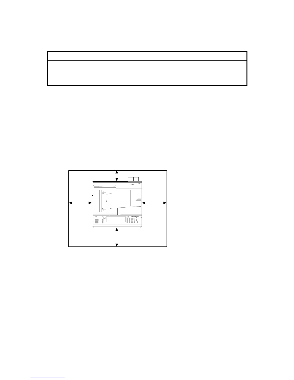
1.1.4 SPACE REQUIREMENTS
B156I501.WMF
A
: Over 100 mm (4")
B: Over 100 mm (4")
C: Over 550 mm (22")
D: Over 750 mm (29.6")
A C
B
D
Page 15
10 February 2005 COPIER (B156/B220)
1-3
Installation
1.2 COPIER (B156/B220)
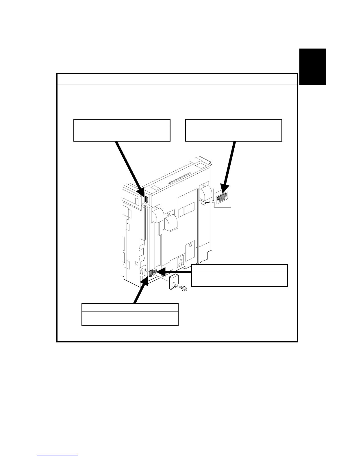
1.2.1 POWER SOCKETS FOR PERIPHERALS
!CAUTION
Rating voltage for peripherals.
Make sure to plug the cables into the correct sockets.
B156I502.WMF
1. ADF
1. Rating voltage output connector
for accessory Max. DC24 V
2. Finisher
1. Rating voltage output connector
for accessory Max. DC24 V
3. By-pass Tray
1. Rating voltage output connector
for accessory Max. DC24 V
4. Duplex Unit
1. Rating voltage output connector
for accessory Max. DC24 V
Page 16
COPIER (B156/B220) 10 February 2005
1-4
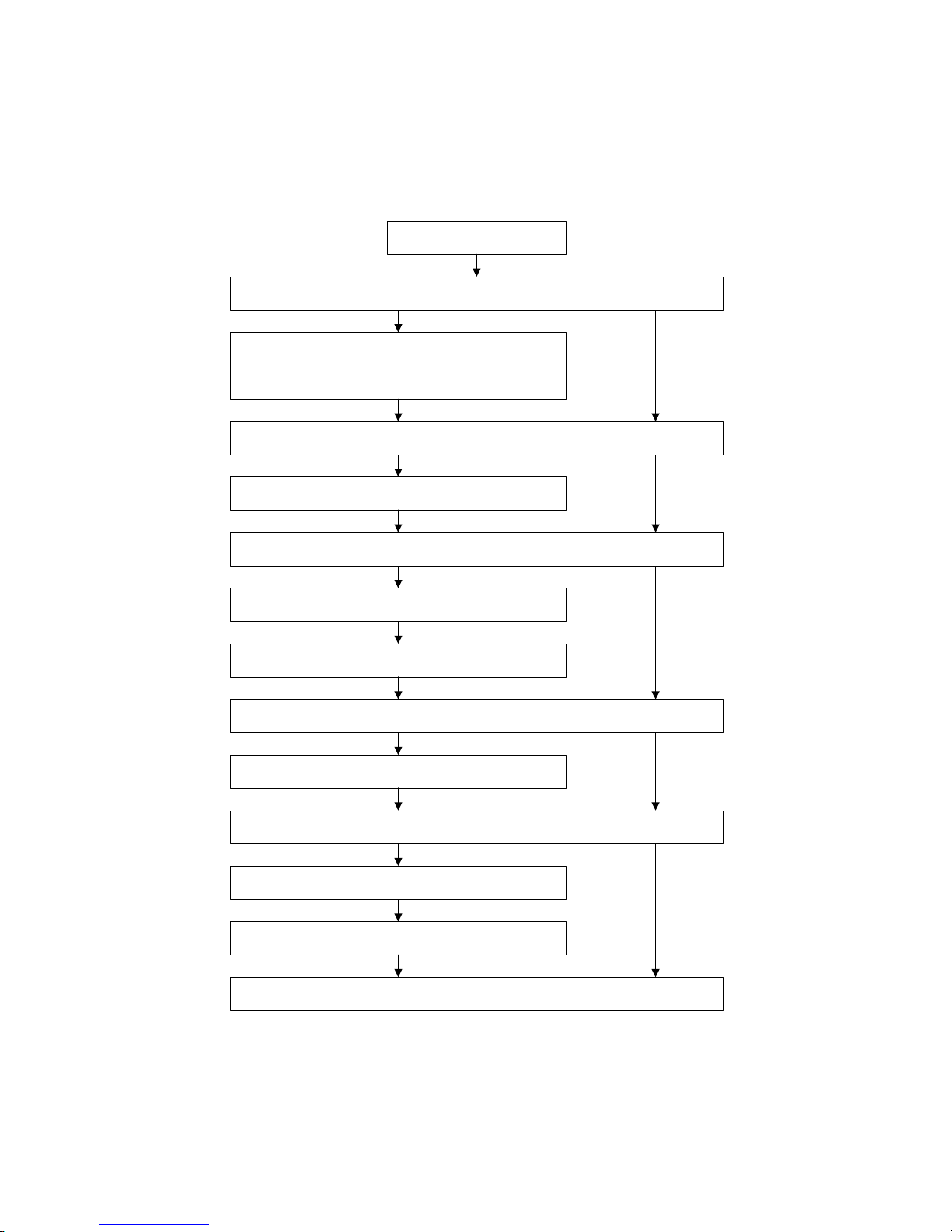
1.2.2 INSTALLATION FLOW CHART
The following flow chart shows how to install the optional units more efficiently.
Unpack the copier
Place the copier on the Paper Tray Unit or LCT
Install the Paper Tray Unit or LCT
Install the copier
Install the By-pass Tray
Yes No
Yes No
Install the Interchange Unit
Install the Duplex Unit and/or 1-bin Tray Unit
Yes No
Install the Shift Tray
Yes No
Install the Bridge Unit
Install the Finisher
Yes No
Does the user require the Paper Tray Unit, LCT, or Finisher?
Does the user require the By-pass Tray?
Install the ARDF or Platen Cover (if required)
Does the user require the Duplex Unit and/or 1-bin Tray Unit ?
Does the user require the Shift Tray?
Does the user require the Finisher?
Yes
B156I503.WMF
Page 17

10 February 2005 COPIER (B156/B220)
1-5
Installation
1.2.3 ACCESSORY CHECK
Check the quantity and condition of the accessories in the box against the following
list:
No. Description Q’ty
1 Paper Tray Decal 1
2 Model Name Decal 1
3 NECR 1
4 Factory Data Sheet 1
5 Filter Duct 3
6 Filter 3
7 Caution Decal – Power/Paper 1
8 Decal – Copy prohibition 1
9 Manual Holder 1
10 Operating Instructions – System Setting 1
11 Operating Instructions – Copy Reference 1
12 Operating Instructions – Printer 2
13 Operating Instructions – Security 1
14 Instruction Procedure Sheet 1
15 Sheet – Notes for User 1
16 Screw for Manual Holder 2
17 Stamp 1
18 Cloth (ADF Standard version only) 1
19 Cloth Holder (ADF Standard version only) 1
Page 18
COPIER (B156/B220) 10 February 2005
1-6
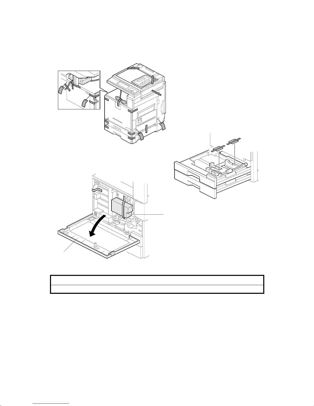
1.2.4 INSTALLATION PROCEDURE
!CAUTION
Unplug the machine power cord before starting the following procedure.
If the optional paper tray or the optional LCT will be installed at the same time,
place the copier on the paper tray unit or the LCT first, then install the copier and
the other options.
NOTE: Keep the shipping retainers after installing the machine. They will be
reused when the machine is moved to another location in the future.
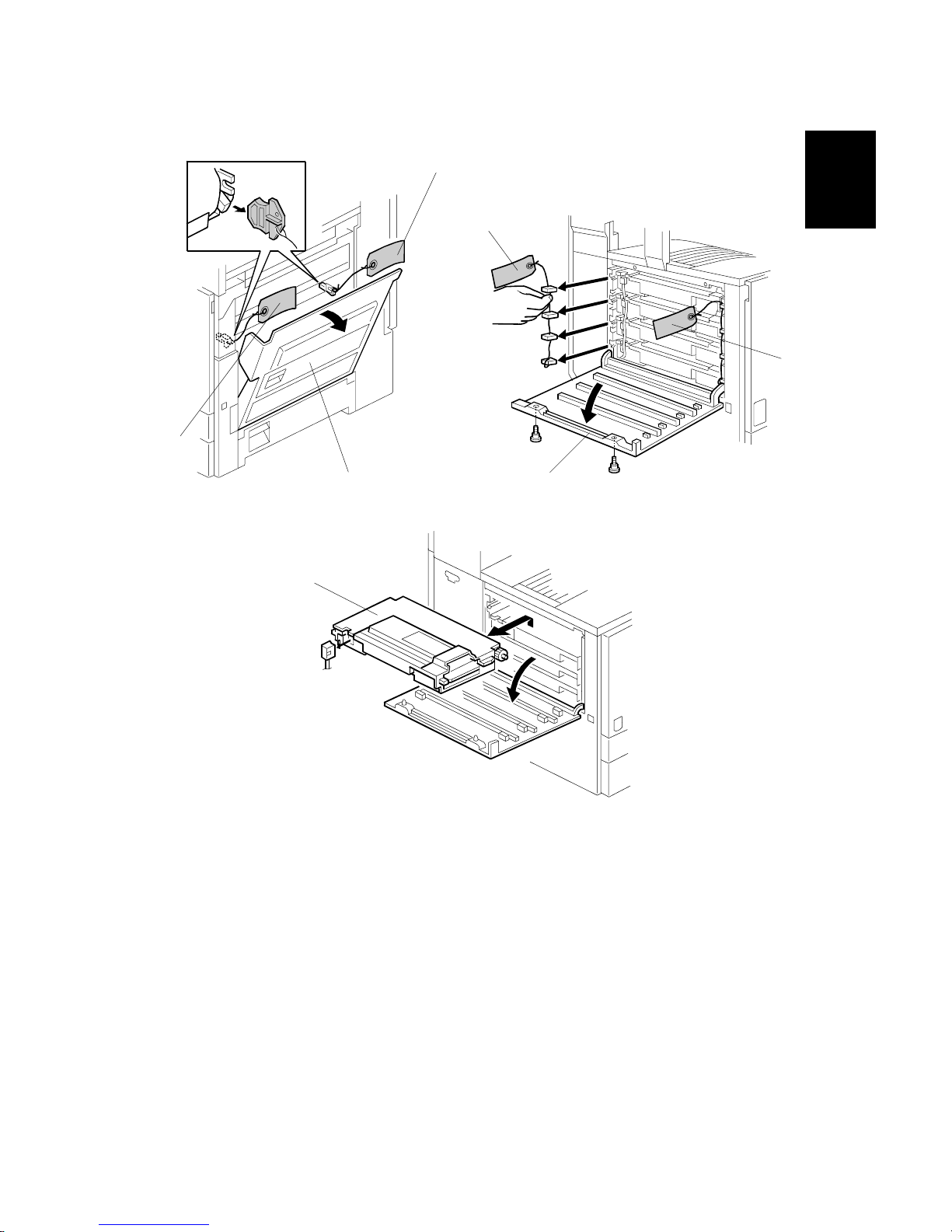
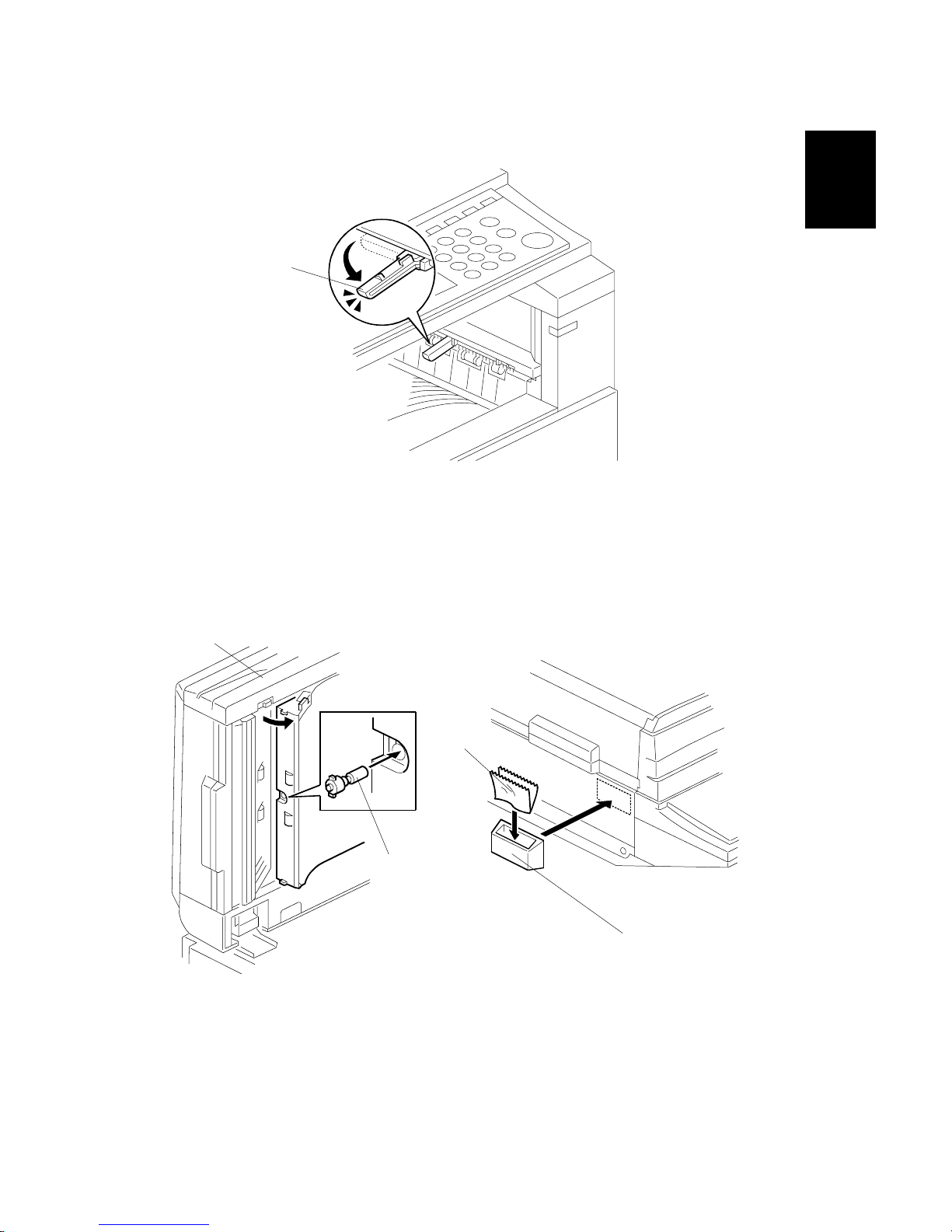
1. Remove the tapes.
2. Open the front cover [A] and remove the shipping retainer [B].
B156I504.WMF
B156I505.WMF
B156I506.WMF
[A]
[B]
Page 19
10 February 2005 COPIER (B156/B220)
1-7
Installation
3. Open the right cover [A], and remove the red tags [B].
4. Open the left cover [C] (! x 2), and remove the red tags [D].
5. Pull out all development units [E] (" x 1 each).
B156I509.WMF
B156I507.WMF
B156I508.WMF
[C]
[D]
[D]
[A]
[B]
[B]
[E]
Page 20
COPIER (B156/B220) 10 February 2005
1-8
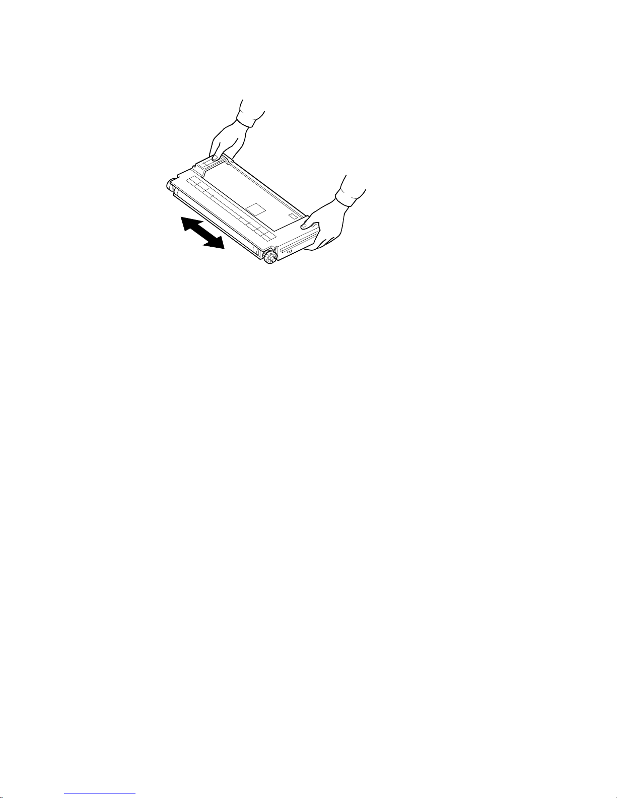
6. Keep the development unit level and shake the development unit about 10
times from side to side.
NOTE: 1) Do not touch the development roller or the development roller gear.
2) Use caution not to drop the cartridge or to damage it.
3) If the cartridge has not been shaken well, the machine takes a
longer time to initialize the development unit, or an error message or
SC350 is displayed. When either of them is displayed, turn the main
switch off and on.
B156I511.WMF
Page 21
10 February 2005 COPIER (B156/B220)
1-9
Installation
7. Reinstall the development units, and close the left cover.
NOTE: A white line or band may appear on one end of the paper if a
development unit is incorrectly installed. To correct this, pull out the
development unit partially (about 30 mm) and slowly reinstall it.
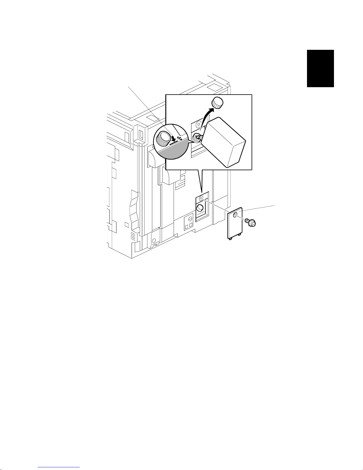
8. Remove the oil tank cover [A] (1 clip), and fill the oil tank to the maximum line.
NOTE: Do not fill the oil tank past the arrow [B].
B156I513.WMF
[A]
[B]
Page 22
COPIER (B156/B220) 10 February 2005
1-10
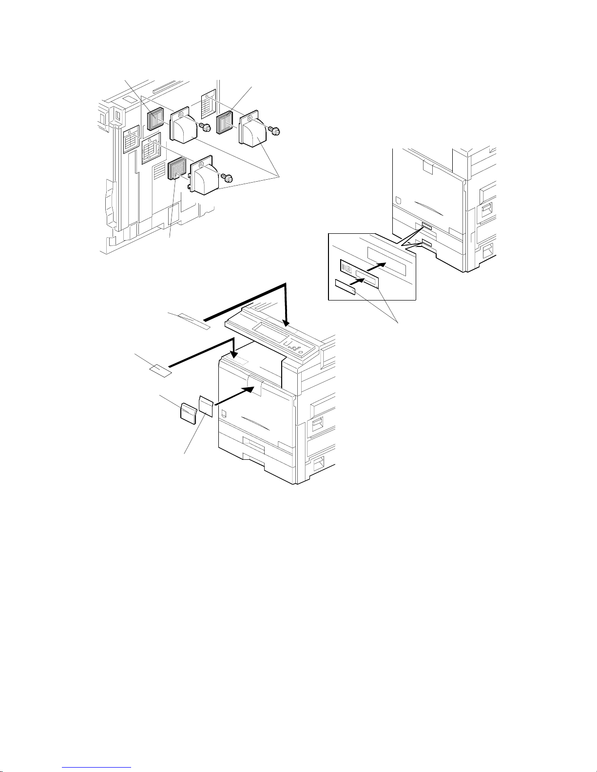
9. Install the filters [A] and ducts [B] as shown.
10. Attach the appropriate model name decal [C] with cover [D] to the front cover.
11. Attach the caution decal [E] to the tray. Attach the copy prohibition decal [F] to
the top.
12. Pull the paper tray out, and adjust the side guides and end guide to match the
paper size.
NOTE: To move the side guides, first pull out the tray fully, then push down the
green lock at the rear inside the tray.
13. Attach the appropriate paper tray number decals [J] to the paper trays.
NOTE: Paper tray number decals are also used for the optional paper tray or
the optional LCT. Keep any remaining decals for use with these
optional units.
B156I514.WMF
B156I516.WMF
B156I515.WMF
[A]
[B]
[A]
[A]
[J]
[C]
[D]
[E]
[F]
Page 23
10 February 2005 COPIER (B156/B220)
1-11
Installation
14. If the optional bridge unit will not be installed: Swing the sensor feeler [A]
out.
15. Install the optional ARDF (EU model only) or the optional platen cover (see
ARDF Installation or Platen Cover Installation).
16. Install the stamp cartridge [B] if the ARDF [C] was installed.
17. Attach the cloth holder [D] to the left side of the scanner as shown. Then put
the cloth [E] in the cloth holder if the ARDF was installed.
B156I517.WMF
B502I006.WMF
B810I504.WMF
[A]
[B]
[C]
[D]
[E]
Page 24
COPIER (B156/B220) 10 February 2005
1-12
18. Plug in the machine and turn the main power switch on. The machine
automatically performs the initialization procedure. After this has finished, the
Start button LED turns green.
19. Make copies of image samples (text, photo, and text/photo modes).
20. Perform Automatic Color Calibration (ACC).
NOTE: Since this machine has been subject to color adjustment using
Automatic Color Calibration (ACC) at the factory, there is no need to
make automatic color calibration again if the customer is satisfied with
the image sample. If the customer is not satisfied, do the following.
1) Print the ACC test pattern (UP mode – Maintenance – ACC – Start).
2) Place the printout on the exposure glass.
3) Place 10 sheets of white paper on top of the test chart. Then, close
the ADF or platen cover.
4) Press “Start Scanning” on the LCD panel. The machine performs the
ACC.
21. If you want to enable the Ethernet NIB function, set SP5-985-001 to “1: enable”.
If you want to enable the USB function, set SP5-985-002 to “1: enable”.
NOTE: The defaults are “0: disabled”.
22. Make sure that the sample image has been copied normally.
23. Remove the double-sided tape from
the manual holder. Then attach it [A] to
the left side of the copier (! x 2).
NOTE: When you install the 1,000-Sheet
Finisher (B408), attach the manual
holder a different location.
B156I532.WMF
[A]
Page 25

10 February 2005 PAPER TRAY UNIT (B456)
1-13
Installation
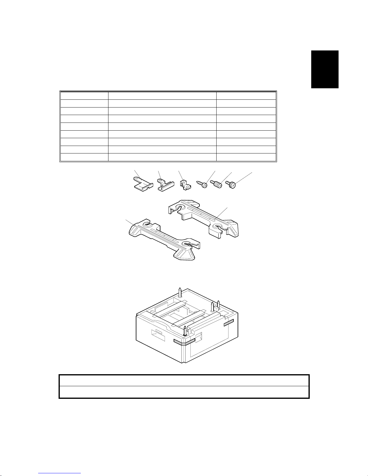
1.3 PAPER TRAY UNIT (B456)
1.3.1 ACCESSORY CHECK
Check the quantity and condition of the accessories against the following list.
No. Description Q’ty
1 Right Stand Bracket 1
2 Left Stand Bracket 1
3 Securing Bracket 2
4 Front Stand 1
5 Rear Stand 1
6 Screw – M4x10 4
7 Knob Screw 2
8 Stepped Screw 2
1.3.2 INSTALLATION PROCEDURE
!CAUTION
Unplug the machine power cord before starting the following procedure.
1. Remove the strips of tape.
B456I001.WMF
B456I002.WMF
1 2 3
4 5
6 7 8
Page 26
PAPER TRAY UNIT (B456) 10 February 2005
1-14
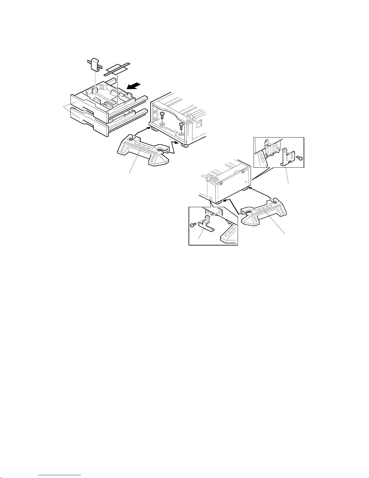
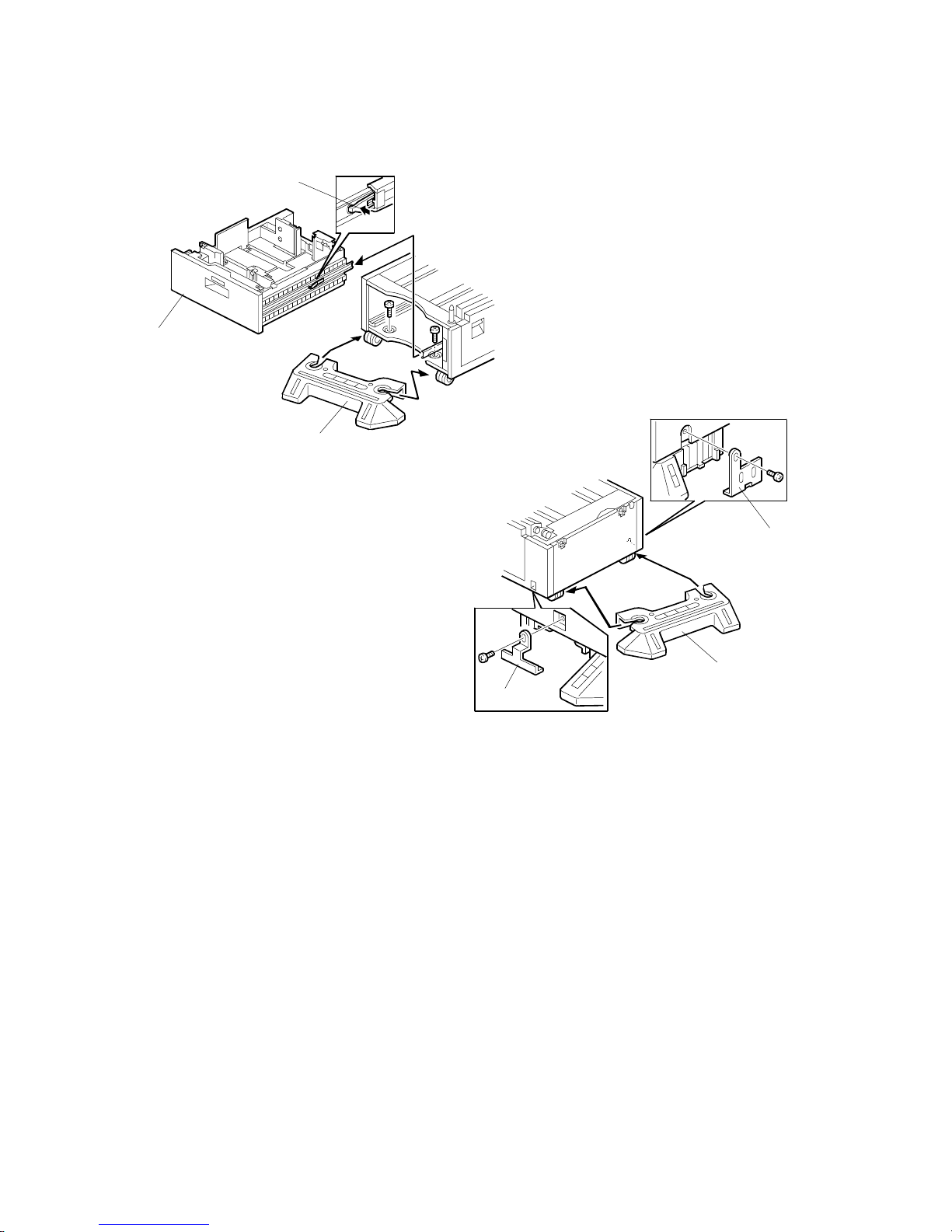
2. Remove the paper trays [A] from the paper tray unit and remove the shipping
retainers.
3. Install the front stand [B] (! x2).
4. Install the rear stand [C].
5. Attach the two stand brackets [D] (! x1 each).
B456I103.WMF
B456I104.WMF
[A]
[B]
[D]
[C]
[D]
Page 27
10 February 2005 PAPER TRAY UNIT (B456)
1-15
Installation
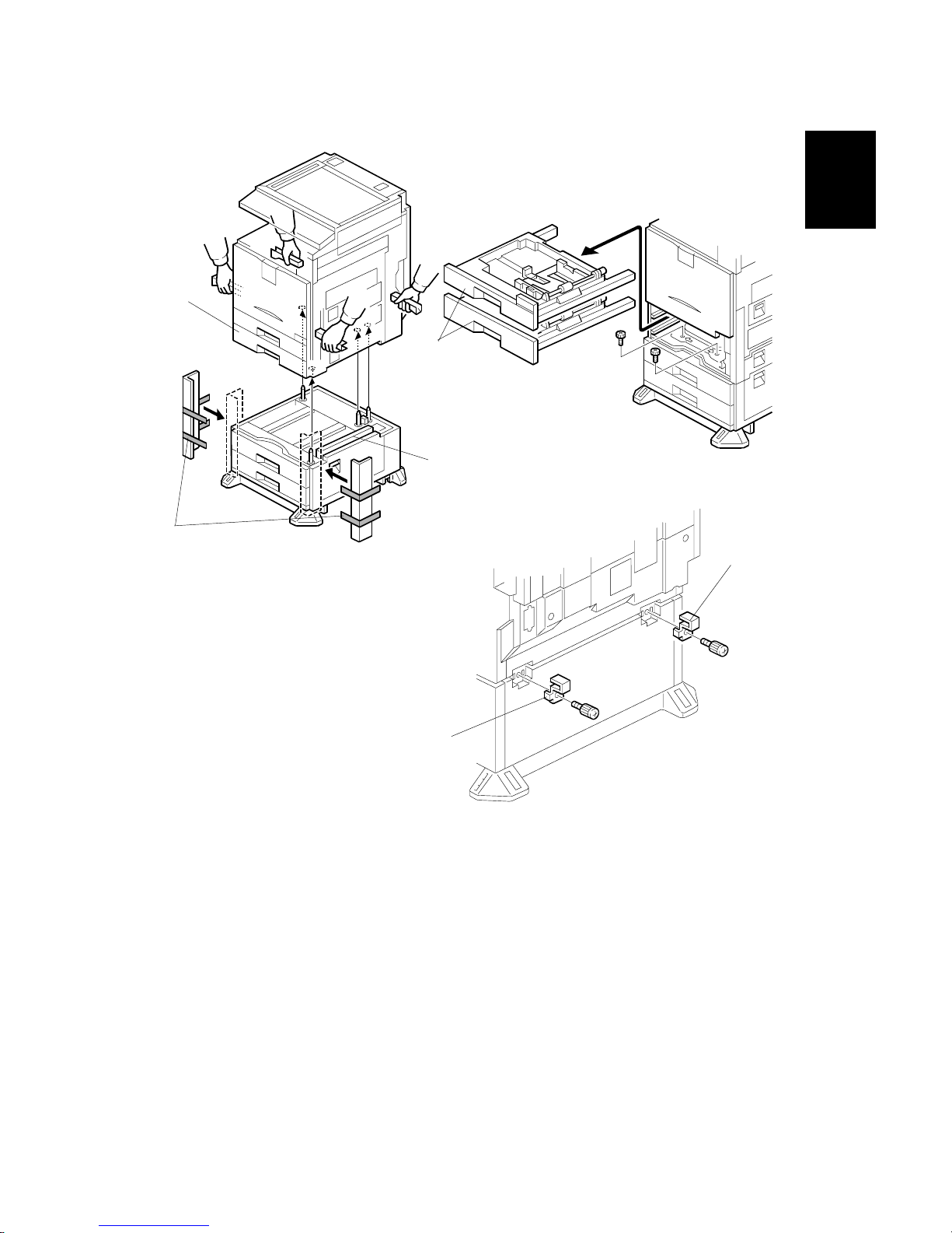
6. Attach the cardboard guides [A] to each side of the paper tray unit [B].
7. Set the copier [C] on the paper tray unit [B]. Use the cardboard guides.
8. Remove the cardboard guides from the paper tray unit.
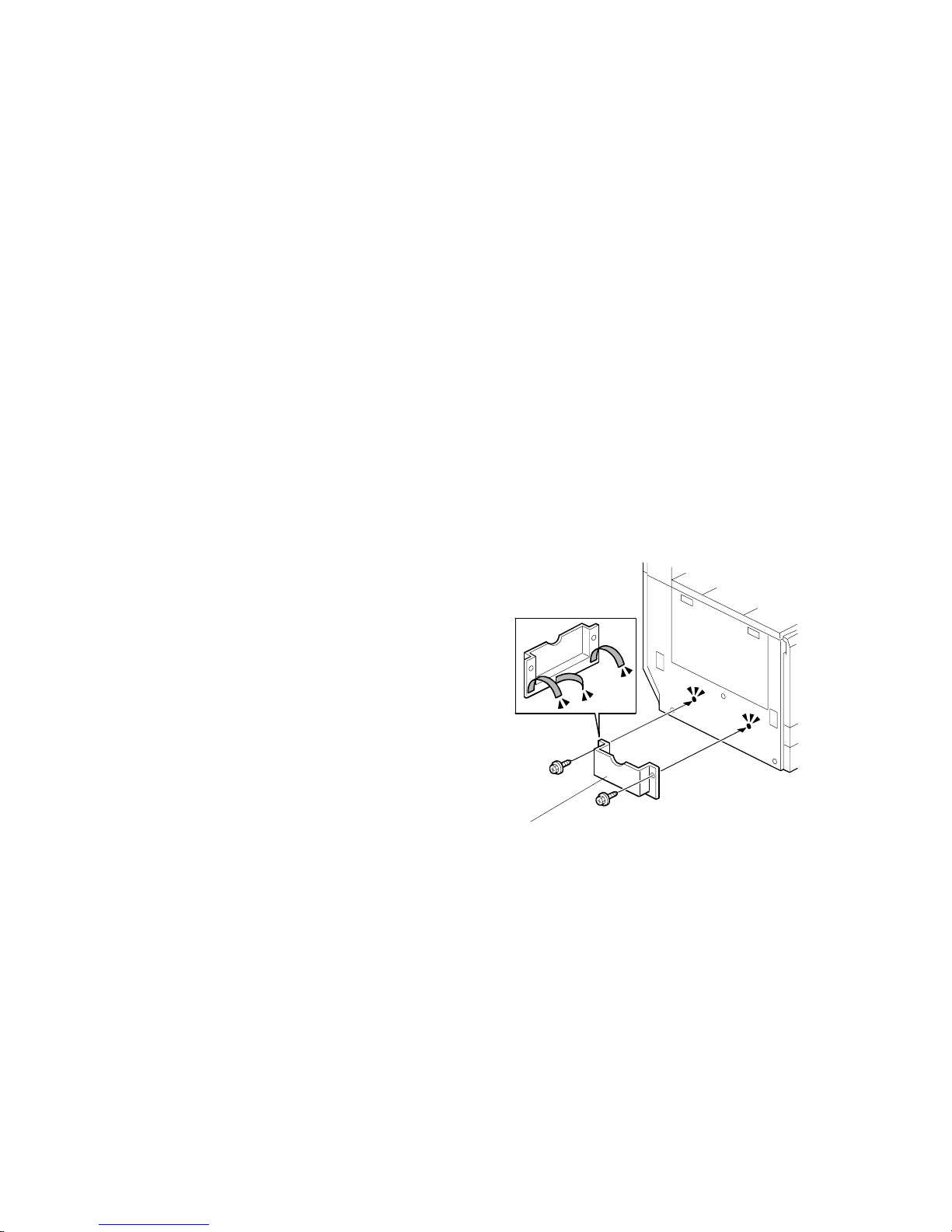
9. Remove the paper trays [D] from the copier and secure the paper tray unit
(! x2).
10. Attach a securing bracket [E] to each side of the paper tray unit, as shown
(! x1 each).
B456I215.WMF
B456I106.WMF
B456I212.WMF
[A]
[B]
[D]
[E]
[E]
[C]
Page 28
10 February 2005
1-16
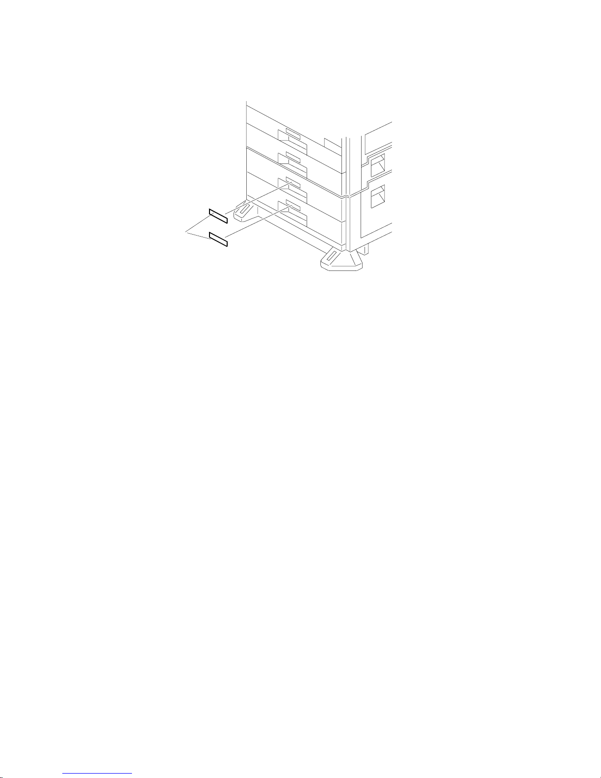
11. Reinstall the paper trays and attach the appropriate paper tray number decal
[A] to the paper tray.
NOTE: The paper tray number decal is in the accessory box for the main
copier.
12. Load paper into the paper trays.
13. Turn on the main switch.
14. Check the machine’s operation and copy quality.
B456I004.WMF
[A]
Page 29
10 February 2005 LCT (B457)
1-17
Installation
1.4 LCT (B457)
1.4.1 ACCESSORY CHECK
Check the quantity and condition of the accessories against the following list.
No. Description Q’ty
1 Right Stand Bracket 1
2 Left Stand Bracket 1
3 Securing Bracket 2
4 Front Stand 1
5 Rear Stand 1
6 Screw – M4x10 4
7 Knob Screw 2
8 Stepped Screw 2
1.4.2 INSTALLATION PROCEDURE
!CAUTION
Unplug the machine power cord before starting the following procedure.
1. Remove the strips of tape.
B457I007.WMF
B457I001.WMF
1
2 3
4
5
6
7 8
Page 30
LCT (B457) 10 February 2005
1-18
2. While pressing the stopper [A] attached to the guide rail, pull out the large
capacity tray [B].
3. Install the front stand [C] (! x2).
4. Install the rear stand [D].
5. Attach the two stand brackets [E] (! x1 each).
B457I003.WMF
B457I104.WMF
[A]
[B]
[E]
[D]
[E]
[C]
Page 31

10 February 2005 LCT (B457)
1-19
Installation
6. Attach the cardboard guides [A] to each side of the LCT [B].
7. Set the copier [C] on the LCT [B]. Use the cardboard guides.
8. Remove the cardboard guides from the LCT.
9. Remove the paper trays [D] from the copier and secure the LCT (! x2).
10. Attach a securing bracket [E] to each side of the LCT, as shown (! x1 each).
B456I215.WMF
B457I152.WMF
B457I156.WMF
[A]
[B]
[D]
[E]
[E]
[C]
Page 32

LCT (B457) 10 February 2005
1-20
11. Reinstall the paper trays and attach the appropriate paper tray number decal
[A] to the LCT.
NOTE: The paper tray number decal is in the accessory box for the main
copier.
12. Load paper into the LCT.
13. Turn on the main switch.
14. Check the machine’s operation and copy quality.
B457I005.WMF
[A]
Page 33

10 February 2005 AUTO REVERSE DOCUMENT FEEDER (B810)
1-21
Installation
1.5 AUTO REVERSE DOCUMENT FEEDER (B810)
1.5.1 ACCESSORY CHECK
Check the quantity and condition of the accessories against the following list.
No. Description Q’ty
1 Scale Guide 1
2 DF Exposure Glass 1
3 Stud Screw 2
4 Knob Screw 2
5 Original Size Decal 2
6 Screwdriver Tool 1
7 Cloth 1
8 Holder 1
1.5.2 INSTALLATION PROCEDURE
!CAUTION
Unplug the copier power cord before starting the following procedure.
1. Remove the strips of tape.
B386I500.WMF
B386I101.WMF
1
2
4
5
3
6
7
8
Page 34

AUTO REVERSE DOCUMENT FEEDER (B810) 10 February 2005
1-22
2. Remove the left scale [A] (! x 2).
3. Peel off the backing [B] of the double-sided tape attached to the glass holder.
4. Place the DF exposure glass [C] on the glass holder.
NOTE: When installing the DF exposure glass, make sure that the white point
[D] is on the lower front side of the glass, as shown.
5. Peel off the backing [E] of the double-sided tape attached to the rear side of the
scale guide [F], then install the scale guide [F] (! x 2 removed in step 2).
6. Install two stud screws [G].
7. Mount the DF on the copier, then slide the DF to the front as shown.
8. Secure the DF unit with two screws [H].
9. Connect the cable [I] to the copier.
B386I107.WMF
B386I108.WMF
[H]
[I]
[H]
[A]
[B]
[C]
[D]
[E]
[F]
[G]
[G]
Page 35

10 February 2005 AUTO REVERSE DOCUMENT FEEDER (B810)
1-23
Installation
10. Peel off the platen sheet [A] and place it on the exposure glass.
11. Line up the rear left corner of the platen sheet flush against corner [B] on the
exposure glass.
12. Close the ARDF.
13. Attach the appropriate scale decal [C] as shown.
14. Turn the main power switch on. Then check if the document feeder works
properly.
15. Make a full size copy. Check that the registrations (side-to-side and leading
edge) and image skew are correct. If they are not, adjust the registrations and
image skew (refer to Replacements and Adjustments – Copy Adjustments).
B386I110.WMF
B386I111.WMF
B386I501.WMF
[A]
[B]
[C]
Page 36

INTERCHANGE UNIT (B481) 10 February 2005
1-24
1.6 INTERCHANGE UNIT (B481)
1.6.1 ACCESSORY CHECK
Check the quantity and condition of the components against the following list.
No. Description Q’ty
1 Interchange Unit 1
B481I101.WMF
Page 37

10 February 2005
1-25
Installation
1.6.2 INSTALLATION PROCEDURE
!CAUTION
Unplug the copier power cord before starting the following procedure.
1. Remove all tapes.
2. Open the right cover [A] of the copier.
3. Open cover [B] and remove it.
4. Remove the connector cover [C] (! x1).
5. Open the cover [D] of the interchange unit.
6. Install the interchange unit [E] (" x1).
NOTE: Take care not to pinch the harness at the front side.
7. Secure the interchange unit with the knob screws [F].
8. Reinstall the connector cover [G] which was removed in step 4 (! x 1).
B481I103.WMF
B481I102.WMF
[A]
[B]
[C]
[D][E]
[F]
[F]
[G]
Page 38

1 BIN TRAY UNIT (B480) 10 February 2005
1-26
1.7 1 BIN TRAY UNIT (B480)
1.7.1 ACCESSORY CHECK
Check the quantity and condition of the components against the following list.
No. Description Q’ty
1 1-Bin Tray Unit 1
2 Tray 1
3 Sub-Tray 1
4 Tray Guide 1
5 Shield Mylar 1
6 Sub Paper Guide 1
7 Paper Guide 1
8 Tapping Screw M3x8 2
B480I101.WMF
1
2
3
4
5
6
7
8
Page 39

10 February 2005 1 BIN TRAY UNIT (B480)
1-27
Installation
1.7.2 INSTALLATION PROCEDURE
!CAUTION
Unplug the copier power cord before starting the following procedure.
NOTE: Before installing this 1-bin tray unit, the optional interchange unit
(B481) must be installed.
1. Remove all tapes.
2. If the optional bridge unit has been installed, open the right jam removal cover
[A] of the bridge unit.
If the optional bridge unit is not installed, skip this step.
B480I107.WMF
[A]
Page 40

1 BIN TRAY UNIT (B480) 10 February 2005
1-28
3. Peel off the backing of the double-sided tape attached to the shield mylar [A].
Then attach the shield mylar to the 1-bin unit, as shown.
4. If the front right cover [B] is installed, remove it (! x1).
5. Remove the cover [C].
6. Install the 1-bin tray unit [D] (! x1).
7. Disconnect the connector [E] and remove the LED board [F].
B480I108.WMF
B480I102.WMF
B480I103.WMF
[A]
[B]
[C]
[D]
[E]
[F]
Page 41

10 February 2005 1 BIN TRAY UNIT (B480)
1-29
Installation
8. Install the LED board [A] on the front right cover (! x1).
9. Reinstall the front right cover [B] (" x2, ! x1).
10. Peel off the backing of the double-sided tape attached to the paper guide [C].
Then attach the paper guide to the underside of the scanner unit as shown.
11. Peel off the backing of the double-sided tape attached to the sub paper guide
[D]. Then attach the sub paper guide to the underside of the scanner unit as
shown.
12. Install the tray guide [E].
13. Install the tray [F].
14. Install the sub-tray [G].
15. Turn on the main power switch and check the 1-bin tray unit operation.
B480I109.WMF
B480I104.WMF
B480I106.WMF
[A]
[B]
[C]
[D]
[E]
[F]
[G]
Page 42

SHIFT TRAY (B510) 10 February 2005
1-30
1.8 SHIFT TRAY (B510)
1.8.1 ACCESSORY CHECK
Check the quantity and condition of the components against the following list.
No. Description Q’ty
1 Shift Tray Unit 1
2 Paper Guide - Large 1
3 Paper Guide - Small 2
4 Stepped Screw 1
5 Core 1
1.8.2 INSTALLATION PROCEDURE
!CAUTION
Unplug the copier power cord before starting the following procedure.
1. Remove all tapes (see the diagram at the top of the page).
2. Remove the covers [A] (! x1).
3. Replace screw [B] with a stepped screw [C].
4. Install the large paper guide [D] and two small paper guides [E], as shown.
B510I111.WMF
B510I102.WMF
[A]
[D]
[E]
[E]
1
2
3
4
[B]
[C]
5
Page 43

10 February 2005 SHIFT TRAY (B510)
1-31
Installation
5. Remove the connector cover [A] (! x 1).
6. Remove the rear cover [B] (! x2).
7. Pass the harnesses [C] through the opening [D], and install the shift tray unit
[E], as shown.
NOTE: 1) Set the shift tray on the stepped screw.
2) The shift tray must be installed under the paper guides [F] installed
in step 4.
B510I103.WMF
B510I211.WMF
[D]
[C]
[B]
[E]
[F]
[A]
Page 44

SHIFT TRAY (B510) 10 February 2005
1-32
8. Remove the screws [A]. (! x 6)
9. Remove the SD-card slot cover [B]. (! x 1)
10. Open the controller box [C].
11. Connect the harness [D], as shown.
12. Attach the harnesses with clamps [E]. Then attach the core [F].
NOTE: Make sure that the core [F] does not cause damage to the harnesses.
13. Assemble the machine.
14. Turn on the main power switch.
15. Check the shift tray operation.
B510I201.WMF
B510I202.WMF
B510I203.WMF
[A]
[A] [B]
[C]
[D]
[E]
[F]
Page 45

10 February 2005 BY-PASS FEED UNIT (B490)
1-33
Installation
1.9 BY-PASS FEED UNIT (B490)
1.9.1 ACCESSORY CHECK
Check the quantity and condition of the components against the following list.
No. Description Q’ty
1 By-pass Tray Unit 1
2 Tapping Screw 3
3 Decal 1
1.9.2 INSTALLATION PROCEDURE
!CAUTION
Unplug the copier power cord before starting the following procedure.
1. Remove all tapes (see the diagram at the top of the page).
2. Remove the entrance cover [A] (!x 2).
B490I001.WMF
B490I113.WMF
1
2
3
[A]
Page 46

BY-PASS FEED UNIT (B490) 10 February 2005
1-34
3. Install the by-pass tray unit [A] (! x3, " x1).
4. Attach the decal [B] as shown.
5. Turn the main power switch on and check the by-pass tray function.
6. Go into the SP mode. Change these SP settings.
SP1003
Default
(No By-pass tray)
By-pass tray
installed
001 0 2
002 –2 0
003 –2 0
004 0 2
Make a copy from the by-pass tray. Then check the registration.
B490I114.WMF
B490I002.WMF
[A]
[B]
Page 47

10 February 2005 DUPLEX UNIT (B509)
1-35
Installation
1.10 DUPLEX UNIT (B509)
1.10.1 ACCESSORY CHECK
Check the quantity and condition of the accessories against the following list.
No. Description Q’ty
1 Duplex Unit 1
2 Upper Bracket 1
3 Rear Holder Bracket 1
4 Front Holder Bracket 1
5 Clip 2
6 Tapping Screw – M4x6 3
7 Tapping Screw – M3x6 1
B509I101.WMF
1
2
3
4
5
6
7
Page 48

DUPLEX UNIT (B509) 10 February 2005
1-36
1.10.2 INSTALLATION PROCEDURE
!CAUTION
Unplug the copier power cord before starting the following procedure.
NOTE: Before installing the duplex unit, the optional interchange unit (B481)
must be installed.
1. Remove all tapes (see the previous page).
2. Remove five covers [A] (! x1).
3. Install three brackets [B] (! x1 each – M4x6).
B509I102.WMF
B509I103.WMF
[A]
[A]
[A]
[B]
[B]
Page 49

10 February 2005 DUPLEX UNIT (B509)
1-37
Installation
4. Set the duplex unit [A] on the brackets [B] (1 clip).
5. Attach the link [C] to the shaft [D] and secure it with the clip.
6. Remove the connector cover [E] (! x1).
7. Connect the cable [F] and secure the grounding wire [G] (! x1).
8. Install the connector cover.
9. Turn on the main power switch and check the duplex unit function.
B509I104.WMF
B509I105.WMF
[A]
[B]
[C]
[D]
[B]
[F]
[E]
[G]
Page 50

BRIDGE UNIT (B482) 10 February 2005
1-38
1.11 BRIDGE UNIT (B482)
1.11.1 ACCESSORY CHECK
Check the quantity and condition of the accessories against the following list.
No. Description Q’ty
1 Bridge Unit 1
2 Rear Joint Bracket 1
3 Front Joint Bracket 1
4 Knob Screw 1
5 Screw – M3x6 1
6 Screw – M4x14 4
7 Core 1
1.11.2 INSTALLATION PROCEDURE
!CAUTION
Unplug the copier power cord before starting the following procedure.
1. Remove all tapes.
2. If the sensor feeler [A] is out, fold it away into the machine.
B482I151.WMF
B482I500.WMF
[A]
1
2
3
4
5 6
7
Page 51

10 February 2005 BRIDGE UNIT (B482)
1-39
Installation
3. Remove the front right cover [A] (! x1).
4. Remove two covers [B] (! x1 each).
5. Remove the connector cover [C] (! x 1).
6. Remove the rear cover [D] (! x2).
7. Pass the harnesses [E] through the opening [F], and install the bridge unit [G]
(! x2).
8. Reinstall the front right cover.
B482I102.WMF
B482I103.WMF
B482I209.WMF
[A]
[B]
[B]
[E]
[F]
[G]
[D]
[C]
Page 52

BRIDGE UNIT (B482) 10 February 2005
1-40
9. Remove the screws [A] (! x 6).
10. Remove the SD-card slot cover [B] (! x 1).
11. Open the controller box [C].
B482I207.WMF
B482I208.WMF
[A]
[A]
[B]
[C]
Page 53

10 February 2005 BRIDGE UNIT (B482)
1-41
Installation
12. Connect the harnesses [A], as shown.
13. Attach the harnesses with clamps [B].
14. Attach the core [C].
NOTE: Make sure that the core does not cause damage to the harnesses.
15. Reinstall the rear cover.
16. When the finisher (Machine code:
B408) will be installed, attach the
front joint bracket [D] and rear joint
bracket [E] (! x2 each).
17. Install the optional finisher (refer to the
finisher installation procedure).
B482I206.WMF
B482I105.WMF
[A]
[C]
[B]
[E]
[D]
Page 54

1000-SHEET FINISHER (B408) 10 February 2005
1-42
1.12 1000-SHEET FINISHER (B408)
1.12.1 ACCESSORY CHECK
Check the quantity and condition of the accessories against the following list.
No. Description Q’ty
For
B022/B027/B031/
B089/B093/B097
For
B051/B052/
B156/B220
For
B079/B082/
B135/B138
1 Front Joint Bracket 1
!
---
!
2 Rear Joint Bracket 1
!
--- ---
3 Rear Joint Bracket 1 --- ---
!
4 Grounding Plate 1
!
---
!
5 Copy Tray 1
! ! !
6 Staple Position Decal 1
! ! !
7 Screw - M4 x 14 4 ! (Use 3) --- ! (Use 4)
8 Knob Screw - M4 x 10 1
! ! !
9 Screw - M3 x 8 1
!
---
!
10 Knob Screw - M3 x 8 1
! ! !
! = Necessary, --- = Not necessary
B408I502.WMF
1
2
3
4
5
8
9
6
7
10
Page 55

10 February 2005 1000-SHEET FINISHER (B408)
1-43
Installation
1.12.2 INSTALLATION PROCEDURE
!CAUTION
Unplug the main machine power cord before starting the following
procedure.
NOTE: The following options must be installed before installing this finisher.
- Bridge Unit (B482)
- Paper Tray Unit (B456) or LCT (B457)
Also, the optional adjustment table (B488) is required.
1. Unpack the finisher and remove the tapes.
B408I102.WMF
B408I103.WMF
[A]
Page 56

1000-SHEET FINISHER (B408) 10 February 2005
1-44
2. Unpack the adjustment table (B488).
3. Set the finisher [A] on the adjustment table [B] and secure the finisher
(! x 1).
4. Install the grounding plate [C] which is in the accessory box for the adjustment
table (! x 2).
5. Open the front door [D], then pull the locking lever [E].
6. Align the finisher on the joint brackets, and lock it in place by pushing the
locking lever.
7. Secure the locking lever (1 knob screw - M3 x 8) and close the front door.
8. Install the copy tray [F] (1 knob screw - M4 x 10).
9. Connect the finisher cable [G] to the main machine.
B408I114.WMF
B408I152.WMF
[D]
[E]
[F]
[G]
[A]
[B]
[C]
Page 57

10 February 2005 1000-SHEET FINISHER (B408)
1-45
Installation
10. Attach the staple position decal [A] to the ARDF as shown.
11. Turn on the main power switch and check the finisher operation.
B408I501.WMF
[A]
Page 58

500-SHEET FINISHER (B458) 10 February 2005
1-46
1.13 500-SHEET FINISHER (B458)
1.13.1 ACCESSORY CHECK
Check the quantity and condition of the accessories against the following list.
No. Description Q’ty
1 Unit Holder 1
2 Entrance Guide 1
3 Shift Tray 1
4 Snap Ring 2
5 Knob Screw 2
B458I102.WMF
1
2
3
4
5
Page 59

10 February 2005 500-SHEET FINISHER (B458)
1-47
Installation
1.13.2 INSTALLATION PROCEDURE
!CAUTION
Unplug the main machine power cord before starting the following
procedure.
NOTE: Before installing the 500-sheet finisher, the optional bridge unit (B482)
must be installed.
1. Unpack the finisher and remove the tapes.
2. Install the entrance guide [A].
3. Remove the holder cover [B]. Then install the unit holder [C] (2 screws).
4. Re-install the holder cover [B].
B458I101.WMF
B458I103.WMF
[A]
[B]
[C]
Page 60

500-SHEET FINISHER (B458) 10 February 2005
1-48
5. Install the 500-sheet finisher [A] (" x1).
6. Install the output tray [B] as shown (2 snap rings).
7. Turn on the main power switch and check the finisher operation.
B458I104.WMF
B458I105.WMF
[A]
[B]
Page 61

10 February 2005 PLATEN COVER INSTALLATION
1-49
Installation
1.14 PLATEN COVER INSTALLATION
1. Install the platen cover [A] (! x 2).
2. Peel off the platen sheet [B] and place it on the exposure glass.
3. Line up the rear left corner of the platen sheet flush against corner [C] on the
exposure glass.
4. Gently close the platen cover.
B156I518.WMF
B156I519.WMF
[A]
[B]
[C]
Page 62

PRINTER OPTIONS 10 February 2005
1-50
1.15 PRINTER OPTIONS
1.15.1 POSTSCRIPT 3 (B769)
!CAUTION
Unplug the main machine’s power cord before starting the following
procedure.
1. Remove the SD-card cover [A] from the machine (! x 1).
2. Make sure that the printed face [B] of the SD card points to the rear of the
machine. Then push it slowly into SD-card slot 2 until you hear a click.
3. Attach the slot cover (! x 1).
4. Attach the “Adobe PostScript 3” decal to the front cover.
B769I001.WMF
[A]
[B]
Page 63

10 February 2005 PRINTER OPTIONS
1-51
Installation
1.15.2 FILE FORMAT CONVERTER (B609)
!CAUTION
Disconnect the main machine’s power cord before you start this procedure.
1. Remove the slot cover [A] from I/F Card Slot A (! x 2).
2. Install the file-format-converter board [B] (Knob-screw x 2).
NOTE: Use a screwdriver when you tighten the knob-screws. Do not tighten
them manually. It can cause this board to disconnect from the machine.
B609I001.WMF
[A]
[B]
Page 64

PRINTER OPTIONS 10 February 2005
1-52
1.15.3 IEEE1394 INTERFACE (B581)
!CAUTION
Unplug the main machine power cord before starting the following
procedure.
NOTE: You can only install one of these network interfaces at the same time: IEEE
802.11b (Wireless LAN), IEEE1284 (Parallel/Centronics), IEEE1394
(FireWire), or Bluetooth.
1. Remove the slot cover [A] from I/F Card Slot B (! x 2).
2. Install the FireWire board [B] (Knob-screw x 2).
NOTE: Use a screwdriver when you tighten the knob-screws. Do not tighten
them manually. It can cause this board to disconnect from the machine.
B581I001.WMF
[A]
[B]
Page 65

10 February 2005 PRINTER OPTIONS
1-53
Installation
UP Mode Settings for IEEE 1394
Enter the UP mode. Then do the procedure below to perform the initial interface
settings for IEEE 1394. These settings take effect every time the machine is
powered on.
1. Press the “User Tools/Counter”key.
2. On the touch panel, press “System Settings”.
3. Press “Interface Settings”.
4. Press “IEEE1394”.
5. Press the following soft keys on the touch panel. Then select the following
settings:
• “IP Address”
Select the “AUTO-Obtain (DHCP) ” or “Specify”. When you select “Specify”,
you can set the IP Address and Subnet Mask manually.
• “IP over 1394”
Enable or disable this setting as required. This setting enables IP over 1394
as the default setting for the printing method.
• “SCSI Print”
Enable or disable this setting as required. This setting enables SCSI Print as
the default setting for the printing method.
• “Bi-directional SCSI Print”
Switch bi-directional printing on or off for SCSI print.
SP Mode Settings for IEEE 1394
The following SP commands can be set for IEEE 1394.
SP No. Name Function
5839 004 Host Name Sets the name of the device used on the network.
Example: RNPXXXXXXXXXX
5839 007 Cycle Master Enables or disables cycle master function of the IEEE
1394 standard bus.
5839 008 BCR Mode Sets the BCR (Broadcast Channel Register) setting for
the Auto Node operation for the standard IEEE1394 bus
for when IRM is not in use. The following three settings
are available: “Standard,” “IRM Color Copy,” and
“Always Effective.”
5839 009 IRM 1394a
Check
Determines whether an IRM check for IEEE 1394a is
conducted for the Auto Node when IRM is not used.
5839 010 Unique ID Enables the “Node_Unique_Id” setting for enumeration
on the standard IEEE 1394 bus.
5839 011 Logout Determines how successive initiator login requests are
handled during login in for SBP-2.
5839 012 Login Enables or disables exclusive login for SBP-2.
5839 013 Login MAX Sets the limit for the number of logins for SBP-2. Range:
1 ~ 62.
Page 66

PRINTER OPTIONS 10 February 2005
1-54
1.15.4 IEEE 1284 (B679)
Installation Procedure
!CAUTION
Disconnect the main machine’s power cord before you start this procedure.
NOTE: You can only install one of these network interfaces at the same time: IEEE
802.11b (Wireless LAN), IEEE1284 (Parallel/Centronics), IEEE1394
(FireWire), Bluetooth.
1. Remove the slot cover [A] from I/F Card Slot B (! x 2).
2. Install the interface board [B] (Knob-screw x 2).
NOTE: Use a screwdriver when you tighten the knob-screws. Do not tighten
them manually. It can cause this board to disconnect from the machine.
B679I001.WMF
[A]
[B]
Page 67

10 February 2005 PRINTER OPTIONS
1-55
Installation
1.15.5 IEEE802.11B (G813)
!CAUTION
Unplug the main machine power cord before starting the following
procedure.
NOTE: You can only install one of the following network interfaces at the same
time: IEEE 802.11b (Wireless LAN), IEEE1284 (Parallel/Centronics),
IEEE1394 (FireWire), Bluetooth.
1. Remove the slot cover [A] from I/F Card Slot B (! x 2).
2. Attach the wireless LAN board [B] to the controller board (Knob-screw x 2).
NOTE: Use a screwdriver when you tighten the knob-screws. Do not tighten
them manually. It can cause this board to disconnect from the machine.
3. Install the wireless LAN card [C]. The printed side must point to the front of the
machine.
4. Attach the antenna cap [D].
G813I001.WMF
[A]
[B]
[C]
[D]
Page 68

PRINTER OPTIONS 10 February 2005
1-56
If wireless LAN reception is not very good, install the extended antenna.
5. Remove the wireless LAN card [A] from the machine.
6. Remove the standard antenna [B] from the wireless LAN card.
7. Install the extended antenna [C] on the LAN card, as shown.
NOTE: The antenna jack must be at the bottom end.
8. Twine the extended-antenna wires seven or eight times.
9. Peel off the backing of the double-sided tape attached to the antenna, and stick
the antenna on the machine.
B529I008.WMF
[A]
[B]
[C]
Page 69

10 February 2005 PRINTER OPTIONS
1-57
Installation
UP Mode Settings for Wireless LAN
Enter the UP mode. Then do the procedure below to perform the initial interface
settings for IEEE 802.11b. These settings take effect every time the machine is
powered on.
NOTE: You cannot use the wireless LAN if you use Ethernet.
1. Press the “User Tools/Counter” key.
2. On the touch panel, press “System Settings”.
NOTE: The Network I/F (default: Ethernet) must be set for either Ethernet or
wireless LAN.
3. Select “Interface Settings” → “Network” (tab) → “Network I/F Setting”
4. Press “IEEE 802.11b”. Only the wireless LAN options show.
5. Communication Mode. Select either “802.11 Ad hoc”, “Ad hoc” or
“Infrastructure”.
6. SSID Setting. Enter the SSID setting. (The setting is case sensitive.)
7. Channel. You need this setting when Ad Hoc Mode is selected.
Range: 1 ~ 14 (default: 11)
NOTE: The allowed range for the channel settings may vary for different
countries.
8. WEP (Encryption) Setting. The WEP (Wired Equivalent Privacy) setting is
designed to protect wireless data transmission. The same WEP key is required
on the receiving side in order to unlock encoded data. There are 64 bit and 128
bit WEP keys.
WEP:
Selects “Active” or “Inactive”. (“Inactive” is default.)
Range of Allowed Settings:
64 bit 10 characters
128 bit 26 characters
9. Transmission Speed. Press the Next button to show more settings. Then
select the transmission speed for the mode: Auto, 11 Mbps, 5.5 Mbps, 2 Mbps,
1 Mbps (default: Auto). This setting should match the distance between the
closest machine or access point. This depends on which mode is selected.
NOTE: For the Ad Hoc Mode, this is the distance between the machine and
the closest PC in the network. For the Infrastructure Mode, this is the
distance between the machine and the closest access point.
11 Mbps 140 m (153 yd.)
5.5 Mbps 200 m (219 yd.)
2 Mbps 270 m (295 yd.)
1 Mbps 400 m (437 yd.)
Page 70

PRINTER OPTIONS 10 February 2005
1-58
10. Press “Return to Default” to initialize the wireless LAN settings.
Press “Yes” to initialize the following settings:
• Transmission mode
• Channel
• Transmission Speed
• WEP
• SSID
• WEP Key
SP Mode Settings for IEEE 802.11b Wireless LAN
The following SP commands and UP modes can be set for IEEE 802.11b
SP No. Name Function
5840 006 Channel MAX Sets the maximum range of the channel settings for the
country.
5840 007 Channel MIN Sets the minimum range of the channels settings
allowed for your country.
5840 011 WEP Key Select Used to select the WEP key (Default: 00).
UP mode Name Function
SSID Used to confirm the current SSID setting.
WEP Key Used to confirm the current WEP key setting.
WEP Mode Used to show the maximum length of the string that can
be used for the WEP Key entry.
Page 71

10 February 2005 PRINTER OPTIONS
1-59
Installation
1.15.6 BLUETOOTH (B736)
!CAUTION
Disconnect the main machine’s power cord before you start this procedure.
NOTE: You can only install one of these network interfaces at the same time: IEEE
802.11b (Wireless LAN), IEEE1284 (Parallel/Centronics), IEEE1394
(FireWire), Bluetooth.
1. Remove the slot cover [A] from I/F Card Slot B (! x 2).
2. Install the Bluetooth board [B] (Knob-screw x 2).
NOTE: Use a screwdriver when you tighten the knob-screws. Do not tighten
them manually. It can cause this board to disconnect from the machine.
3. Install the Bluetooth card [C] in the slot of the Bluetooth board.
4. Attach the antenna cap [D].
B736I001.WMF
[A]
[B]
[C]
[D]
Page 72

PRINTER OPTIONS 10 February 2005
1-60
1.15.7 CHECKING THE CONNECTIONS
1. Plug in the power cord and turn on the main switch.
2. Enter the printer user mode and print the configuration page.
(User Tools/ Printer Settings/ List Test Print/ Config. Page)
The same data can also be printed using the printer service mode.
(“Print Summary”: SP1-004)
All installed options are listed in the “System Reference” column.
Page 73

10 February 2005 DATA OVERWRITE SECURITY UNIT (B735)
1-61
Installation
1.16 DATA OVERWRITE SECURITY UNIT (B735)
ACCESSORY CHECK
Check the quantity and condition of these accessories.
Description Q’ty
1. SD Card..............................................................................1
2. Operation Instructions (CD-ROM) ......................................1
Seal Check and Removal
!CAUTION
Before you start the installation, you must check the box seals to make
sure that they were not removed after the items were sealed in the box at
the factory.
1. Check the box seals [A] on each corner of the box.
• Make sure that a tape is attached to each corner.
• The surfaces of the tapes must be blank. If you see “VOID” on the tapes, do
not install the components in the box.
2. If the surfaces of the tapes do not show “VOID”, remove them from the corners
of the box.
3. When you remove each seal, the “VOID” marks [B] can be seen. In this
condition, they cannot be attached to the box again.
B735I901.WMF
B735I903.WMF
[B]
[A]
Page 74

DATA OVERWRITE SECURITY UNIT (B735) 10 February 2005
1-62
Installation Procedure
!CAUTION
The machine must always be turned off and its power cord disconnected
before you do this procedure.
NOTE: You must install the data overwrite protection unit in SD Card slot 2. But,
the postscript option for this machine is also installed in SD Card slot 2.
Because of this, you must do the SD Card Appli move procedure first (☛
5.9) if the postscript option is installed and you want to install the Data
Overwrite Security unit. Move the Data Overwrite Security application (slot
3) to the SD Card that contains the Printer/Scanner application (slot 1).
1. If the machine is on, turn off the main power switch.
2. Disconnect the network cable.
3. Turn the main power switch on.
4. Do the “Copy SPs” in the table below.
SP No. SP Name Set To:
5871-001 HDD Function Disable 1 (On)
5967-001 Copy Server Set Function 1 (Off)
5846-090 USC Settings - Plain Data Forbidden 1 (Check)
5836-001 Capture Setting – Capture Function 1 (On)
5. Do the “Printer SP” in the table below.
SP No. SP Name Set To:
1006-001 Sample/Locked Print 1 (On)
Page 75

10 February 2005 DATA OVERWRITE SECURITY UNIT (B735)
1-63
Installation
6. Turn the operation switch and
main power switch off.
7. Remove the slot cover [A] (! x 1).
8. Turn the SD-card face [B] to the
rear of the machine. Then push it
slowly into slot 2 until you hear a
click.
9. Connect the network cable, if the
NIB option is installed.
10. Turn the main power switch on.
11. Go into the SP mode. Do SP5878 and push ‘EXECUTE’.
12. Go out of the SP mode, turn the
operation switch off, then turn the
main power switch off.
13. Turn the machine power on.
14. Go into the User Tools mode, and select System Settings> Administrator
Tools> Auto Erase Memory Setting> On.
15. Go out of the User Tools mode.
16. Check the display and make sure that the overwrite erase icon [A] is displayed.
17. Make a Sample Copy.
18. Check the overwrite erase icon.
• The icon [C] changes to [D] when job data is stored in the hard disk.
• The icon goes back to its usual shape [E] after this function has completed a
data overwrite operation to the hard disk.
19. Remove the Document Server and Scanner key-tops, and replace them with
the blank key-tops that are supplied with the kit.
B735I001.WMF
B735I905.WMF
CopiesTotalOrigi
.
010
09/09/2003 14:13
B735I904.WMF
[C]
[D] [E]
[A]
[B]
Page 76

KEY COUNTER INSTALLATION 10 February 2005
1-64
1.17 KEY COUNTER INSTALLATION
!CAUTION
Unplug the main machine power cord before starting the following
procedure.
1. Remove the connector cover [A] (! x 1).
2. Remove the rear cover [B] (! x 2).
3. Remove the upper right cover [C] (! x 2).
4. Remove the cap [D].
5. Install the bracket [E] (! x 2).
6. Connect the cable [F] to the I/O board and route it as shown.
NOTE: If the cable is installed correctly, the length [G] is about 140 mm.
B156I520.WMF
B156I524.WMF
B156I552.WMF
[B]
[C]
[D]
[E]
[F]
[A]
[G]
Page 77

10 February 2005 KEY COUNTER INSTALLATION
1-65
Installation
7. Hold the key counter plate nuts [A] on the inside of the key counter bracket [B]
and insert the key counter holder [C].
8. Secure the key counter holder to the bracket (! x 2).
9. Install the key counter cover [D] (! x 2).
10. Install the stepped screw [E].
11. Connect the cable [F].
12. Hook the key counter holder assembly [G] onto the stepped screw and secure
it (! x 1).
13. The restricted access control for the key counter is enabled by the Copier UP
mode.
B156I526.WMF
B156I527.WMF
[A]
[B]
[C]
[D]
[E]
[F]
[G]
Page 78

ANTI-CONDENSATION HEATER 10 February 2005
1-66
1.18 ANTI-CONDENSATION HEATER
!CAUTION
Unplug the main machine power cord before starting the following
procedure.
1. Remove the connector cover [A] (! x 1).
2. Remove the rear cover [B] (! x 2).
3. Remove the lower rear cover [C] (! x 2).
4. Remove the oil tank [D].
NOTE: Hang the left oil pipe [E] in the notch [F] in the controller box. Then, oil
does not fall from the pipe to the floor.
5. Connect the two connectors [G].
6. Install the oil tank at its initial position.
NOTE: When you install the oil tank, make sure that the position of the mark
[H] on the oil pipe is as shown in the diagram above. If you do not do
this, the oil is not correctly supplied to the fusing unit.
B156I620.WMF
B156I531.WMF
[B]
[A]
[C]
[D]
[G]
[H]
[F]
[E]
Page 79

10 February 2005 ANTI-CONDENSATION HEATER
1-67
Installation
7. Remove the rear scale [A] (! x 3), left scale [B] (! x 2), and exposure glass
[C].
NOTE: When installing the exposure glass, make sure that the mark [D] is
positioned at the rear left corner, as shown.
8. Install the anti-condensation heater [E] (! x 2, " x 1).
9. Reinstall the exposure glass and the scales.
B156I528.WMF
B156I529.WMF
[A]
[B]
[C]
[D]
[E]
Page 80

TRAY HEATER 10 February 2005
1-68
1.19 TRAY HEATER
!CAUTION
Unplug the main machine power cord before starting the following
procedure.
1. Remove the connector cover [A] (! x 1).
2. Remove the rear cover [B] (! x 2).
3. Remove the lower rear cover [C] (! x 2).
4. Slide out the 1st and 2nd paper trays.
5. Pass the connector [D] through the opening [E].
6. Install the tray heater assembly [F](! x 1).
B156I620.WMF
B156I530.WMF
[B]
[D]
[E]
[F]
[A]
[C]
Page 81

10 February 2005 TRAY HEATER
1-69
Installation
7. Remove the oil tank [A].
NOTE: Hang the left oil pipe [B] in the notch [C] in the controller box. Then, oil
does not fall from the pipe to the floor.
8. Connect the two connectors [D].
9. Install the oil tank at its initial position.
NOTE: When you install the oil tank, make sure that the position of the mark
[E] on the oil pipe is as shown in the diagram above. If you do not do
this, the oil is not correctly supplied to the fusing unit.
10. Connect the heater cable to the ac cable [F].
11. Reassemble the machine.
B156I531.WMF
B156I551.WMF
[A]
[D]
[E]
[F]
[C]
[B]
Page 82

TRAY HEATER (OPTIONAL PAPER TRAY UNIT) 10 February 2005
1-70
1.20 TRAY HEATER (OPTIONAL PAPER TRAY UNIT)
!CAUTION
Unplug the main machine power cord before starting the following
procedure.
1. Remove the connector cover [A] (! x 1).
2. Remove the rear cover for the main machine [B] (! x 2).
3. Remove the lower rear cover [C] (! x 2).
4. Remove the joint brackets [D] (! x 1 each).
5. Remove the rear cover for the optional paper tray unit [E] (! x 2).
6. Slide out the paper trays from the optional paper tray unit.
B456I620.WMF
B456I502.WMF
[B]
[E]
[D]
[D][A]
[C]
Page 83

10 February 2005 TRAY HEATER (OPTIONAL PAPER TRAY UNIT)
1-71
Installation
7. Pass the connector [A] through the opening [B].
8. Install the tray heater [C] (! x 1).
9. Connect the heater connector [D] to the cable [E].
10. Remove the oil tank [F].
NOTE: Hang the left oil pipe [G] in the notch [H] in the controller box. Then, oil
does not fall from the pipe to the floor.
11. Install the clamp [I].
NOTE: Make sure that the ac cable [J] from the main machine goes behind the
bracket [K].
12. Connect the cable to the ac cable [J]. Then attach the cable with the clamp.
13. Install the oil tank and the rear covers.
NOTE: When you install the oil tank, make sure that the position of the mark
[L] on the oil pipe is as shown in the diagram above. If you do not do
this, the oil is not correctly supplied to the fusing unit.
B456I201.WMF
B456I292.WMF
[A]
[B]
[C]
[E]
[F]
[H]
[D]
[J]
[I]
[K]
[L]
[G]
Page 84

TRAY HEATER (OPTIONAL LCT) 10 February 2005
1-72
1.21 TRAY HEATER (OPTIONAL LCT)
!CAUTION
Unplug the main machine power cord before starting the following
procedure.
1. Remove the connector cover [A] (! x 1).
2. Remove the rear cover for the main machine [B] (! x 2).
3. Remove the lower rear cover [C] (! x 2).
4. Remove the joint brackets [D] (! x 1 each).
5. Remove the rear cover for the optional LCT [E] (! x 2).
6. Slide out the paper tray [F] from the optional LCT.
7. Push stopper [G] on the right slide rail and remove the paper tray.
B457I620.WMF
B457I502.WMF
B457I501.WMF
[E]
[D]
[D]
[B]
[F]
[G]
[A]
[C]
Page 85

10 February 2005 TRAY HEATER (OPTIONAL LCT)
1-73
Installation
8. Pass the connector [A] through the opening [B].
9. Install the tray heater [C] (! x 1).
10. Connect the heater connector [D] to the cable [E].
11. Remove the oil tank [F].
NOTE: Hang the left oil pipe [G] in the notch [H] in the controller box. Then, oil
does not fall from the pipe to the floor.
12. Install the clamp [I].
NOTE: Make sure that the ac cable [J] from the main machine goes behind the
oil bracket [K].
13. Connect the cable to the ac cable [J]. Then attach the cable with the clamp.
14. Install the oil tank and the rear covers.
NOTE: When you install the oil tank, make sure that the position of the mark
[L] on the oil pipe is as shown in the diagram above. If you do not do
this, the oil is not correctly supplied to the fusing unit.
B457I251.WMF
B457I291.WMF
[A] [B]
[C]
[D]
[E]
[F] [I]
[J]
[H]
[K]
[L]
[G]
Page 86

10 Februry 2005 MAIN UNIT
2-1
Preventive
Maintenance
2. PREVENTIVE MAINTENANCE
2.1 MAIN UNIT
2.1.1 OVERVIEW
B156P501.WMF
Oil supply unit
PCU
Fusing subunit
Charge corona unit
Page 87

MAIN UNIT 10 February 2005
2-2
2.1.2 WASTE TONER BOTTLES
IMPORTANT: You must remove toner from the waste toner bottles during each service
call.
B156P502.BMP
B156P503.BMP
O/B waste
toner bottle
T/B waste
toner bottle
Page 88

10 Februry 2005 MAIN UNIT
2-3
Preventive
Maintenance
2.1.3 PM TABLE
After replacing a part, reset the PM counter for that part (SP 7-804).
Abbreviations: Clean, Inspect, Oil replenishment, Replace, Emergency Maintenance
Optical System
Prints Developments
70K 80K 120K 70K 120K 240K
EM Remarks
White plate C Optical cloth
1st mirror C Optical cloth
2nd mirror C Optical cloth
3rd mirror C Optical cloth
Front/rear rails C Damp/dry cloth
Exposure glass C C Glass cleaner
Dust shield glass
(laser optics unit)
C C
Optical cloth and dry
cloth
APS sensors C Dry cloth
Around the PCU
Prints Developments
70K 80K 120K 50K 120K 240K
EM Remarks
Charge corona unit
R
Replace as whole units
or individual parts
(listed below).
PCU R
T/B waste toner bottle R C Empty the bottle
ID sensor C Blower brush
O/B waste toner bottle C R C Empty the bottle
Components Parts of the Charge Corona Unit
Prints Developments
70K 80K 120K 50K 120K 240K
EM Remarks
Charge Corona Wire R
Charge Corona Grid R
Charge Corona Cleaner R
Development Unit
Prints Developments
70K 80K 120K 60K 120K 240K
EM Remarks
Development unit-C R
Development unit-M R
Development unit-Y R
Development unit-K
R
Refer to the PM
counter for each unit.
Do SP 3-929 after you
replace a development
unit (see section 3.5
for details).
(
Not reclaimed at the
reclamation center)
Page 89

MAIN UNIT 10 February 2005
2-4
Paper Feed System
Prints Developments
70K 80K 120K 75K 120K 240K
EM Remarks
Idle roller (registration) C Damp/dry cloth
Registration sensor C Damp/dry cloth
Transport guide C Damp/dry cloth
Feed roller (main unit) R
Vertical transport roller C Damp/dry cloth
Friction pad (main unit) R
Fusing Unit
Prints Developments
60K 80K 120K 75K 120K 240K
EM Remarks
Fusing subunit R
Oil supply unit
R
Replace as whole units
or individual parts
(listed below).
Thermistor I
Fusing oil O
.Components Parts of the Fusing Sub Unit and Oil Supply Unit
Prints Developments
60K 80K 120K 75K 120K 240K
EM Remarks
Oil supply pad
R
I, C See Note 1
Sponge roller
R I, C See Note 1
Fusing cleaning roller
R
Rear oil absorber R
Front oil absorber
R
Front oil tank absorber
R
Long oil tank absorber
R
Rear oil tank absorber
R
Fusing cover absorber
R
Oil supply roller
R
I, C See Note 1
Oiling roller
R
I, C See Note 1
Pressure cleaning roller
R
Fusing belt unit
R
I, C See Note 1
Pressure roller
R
Pressure roller strippers
R
Idle gear – 28Z/35Z
R
Gear – 47Z
R
Front spring plate
R
Rear spring plate
R
Note 1: Carefully remove paper dust and toner (for example, with a dry cloth).
Page 90

10 Februry 2005 MAIN UNIT
2-5
Preventive
Maintenance
Filters
Prints Developments
70K 80K 120K 75K 120K 240K
EM Remarks
Exhaust filters R
Ozone filter R
Others
Prints Developments
70K 80K 120K 75K 120K 240K
EM Remarks
Breaker
Check the function
once a year. See
section 3.16.
By-pass Tray Unit
Prints Developments
70K 80K 120K 75K 120K 240K
EM Remarks
Feed roller R
Pickup roller R
Separation roller R
Friction pad C Damp cloth
Page 91

OPTIONAL UNIT PM TABLE 10 February 2005
2-6
2.2 OPTIONAL UNIT PM TABLE
Abbreviations: Clean, Inspect, Oil replenishment, Replace, Emergency Maintenance
Duplex Unit
Prints Developments
70K 80K 120K 75K 120K 240K
EM Remarks
Idle roller (inverter) C Damp/dry cloth
Idle roller
(vertical transport)
C
Damp/dry cloth
Auto-reverse Document Feeder
Prints Developments
70K 80K 120K 75K 120K 240K
EM Remarks
Pickup roller R
Feed belt R
Separation roller R
Stamp I
ADF exposure glass C C Damp/dry cloth
Platen cover C C Damp/dry cloth
Paper Tray Unit
Prints Developments
70K 80K 120K 75K 120K 240K
EM Remarks
Pickup roller R
Feed roller R
Separation roller R
Large Capacity Tray
Prints Developments
70K 80K 120K 75K 120K 240K
EM Remarks
Pickup roller R
Feed roller R
Separation roller R
Page 92

10 February 2005 SPECIAL TOOLS
3-1
Replacement
Adjustment
3. REPLACEMENT AND ADJUSTMENT
CAUTION
Turn off the main power switch and unplug the machine before beginning
any of the procedures in this section.
NOTE: This manual uses the following symbols.
: See or Refer to : Screws : Connector : Clip ring
: E-ring
3.1 SPECIAL TOOLS
Part Number Description Q’ty
A0069104 Scanner Positioning Pin (4 pcs/set) 1
B6456700 SD Card 1
B6456800 USB SD Card Adapter 1
A0929503 C4 Color Test Chart (3 pcs/set) 1
C4019503 20X Magnification Scope 1
3.2 FILTERS
1. Filter covers [B, D, and E]
2. Exhaust filters [A, C, G, and I]
3. Filter holder [F]
4. Ozone filter [H]
B156R819.WMF
[A]
[B]
[C]
[D]
[E]
[F]
[G]
[H]
[I]
Page 93

SCANNER UNIT 10 February 2005
3-2
3.3 SCANNER UNIT
3.3.1 EXPOSURE GLASS
1. Rear scale [A] ( x 3)
2. Left scale [B] ( x 2)
NOTE: After replacing the left scale,
adjust the scanner white level
( 3.14).
3. Exposure glass [C]
NOTE: When reassembling, position the
glass marker [D] at the rear-left
corner.
3.3.2 APS SENSORS
1. Exposure glass ( 3.3.1)
2. Original length sensor 1 [A]
( x 1, x 1)
3. Original length sensor 2 [B]
( x 1, x 1)
4. Original width sensor [C]
( x 1, x1)
B156R222.WMF
B156R223.WMF
[A]
[B]
[C]
[A]
[C]
[B]
[D]
Page 94

10 February 2005 SCANNER UNIT
3-3
Replacement
Adjustment
3.3.3 LENS BLOCK ASSEMBLY
1. Exposure glass ( 3.3.1)
2. Rear cover ( 3.4.2)
3. Scanner right cover [A] ( x 2)
4. Inner cover [B] ( x 4)
5. Lens block assembly [C]
( x 4, x 4)
NOTE: Do not remove the paint-
locked screws.
6. After reassembling, input the data
in accordance with the data sheet
included in the spare SBU unit (
SP4-540).
Refer to the diagram on the next
page.
• Row No. 1: Numbers 1 to 6 –
please ignore
• Row No. 2: Numbers 7 to 10 –
please store in the following SP
modes
7: SP 4-540-001
8: SP 4-540-002
9: SP 4-540-003
10: SP 4-540-004
• Row No. 3: Numbers 11 to 14 – please store in the following SP modes
11: SP 4-540-021
12: SP 4-540-022
13: SP 4-540-023
14: SP 4-540-024
• Before inputting the number, check whether it is + or – (look at the data
sheet), then input a +ve or –ve number accordingly.
7. Check the registrations ( SP4-010/011 Chapter 3, Copy adjustments)
NOTE: After replacing the left scale, adjust the scanner white level ( 3.14).
B156R004.WMF
B156R224.WMF
[B]
[C]
[A]
Page 95

SCANNER UNIT 10 February 2005
3-4
B156R999.JPG
Page 96

10 February 2005 SCANNER UNIT
3-5
Replacement
Adjustment
3.3.4 EXPOSURE LAMP STABILIZER
1. Rear cover ( 3.4.2)
2. Exposure lamp stabilizer bracket [A]
( x 2, x 2)
3. Exposure lamp stabilizer [B] ( x 2)
3.3.5 SCANNER LAMP
1. Exposure glass ( 3.3.1)
2. Rear cover ( 3.4.2)
3. Operation panel [A]
( x 5, x 1)
4. Scanner right cover [B] ( x 2)
5. Scanner left cover [C] ( x 1)
6. Scanner rear cover [D] ( x 1)
7. Left frame [E] ( x 2)
8. Front frame [F] ( x 5)
B156R007.WMF
B156R002.WMF
B156R225.WMF
[A]
[B]
[C]
[F]
[E]
[D]
[A]
[B]
Page 97

SCANNER UNIT 10 February 2005
3-6
9. Scanner I/O board ( 3.3.6)
10. Rear frame with the rear rail frame [A]
( x 8, x 1)
11. Lamp guard [B] ( x 2)
12. Release the cable holder [C].
13. Pulley [D]
NOTE: Use caution not to
bend the pulley guides.
14. Push down the part [E]
15. Slide out the scanner lamp [F]
NOTE: After replacing the
scanner lamp, adjust
the scanner white level
( 3.14).
B156R103.WMF
B156R101.WMF
[B]
[F]
[D]
[E]
[C]
[A]
Page 98

10 February 2005 SCANNER UNIT
3-7
Replacement
Adjustment
16. Disconnect the connector [A].
17. Remove the paper length sensor [B]
( x 1).
18. Remove the scanner lamp cable (
[C] with a screw).
19. Remove the cable guide [D].
Reassembling
• When you install the scanner lamp,
make sure that the binding [E] is set as
shown. Also, make sure that the cable
that has a black tube is installed on the
cable guide as shown [F].
• The cable must not be loose. Move the
clamp [G] to adjust the tension in the
cable.
B156R102.WMF
NG
OK
B156R104.WMF
[A]
[B]
[C]
[D]
[F]
[G]
[E]
Page 99

SCANNER UNIT 10 February 2005
3-8
3.3.6 SCANNER I/O BOARD
1. Scanner right cover and scanner
rear cover ( 3.3.5)
2. Scanner I/O board [A]
( x 6, x 7)
3.3.7 SCANNER MOTOR
1. Scanner I/O board ( 3.3.6)
2. Scanner motor [A] ( x 2, Spring x 1)
3. Timing belt [B]
3.3.8 FRONT SCANNER WIRE
1. Front frame ( 3.3.5)
2. To make reassembly easy, slide the
first scanner to the right
( Reassembling the Front Scanner
Wire).
3. Front scanner wire clamp [A]
4. Front scanner wire bracket [B]
( x 1)
5. Front scanner wire and scanner drive
pulley [C] ( x 1)
B156R006.WMF
B156R008.WMF
B156R226.WMF
[A]
[A]
[B]
[A]
[B]
[C]
Page 100

10 February 2005 SCANNER UNIT
3-9
Replacement
Adjustment
Reassembling the Front Scanner Wire
1. Pass the end with the ball [A] through
the left square hole from the front.
2. Position the center ball [B] in the
middle of the notch, as shown by the
arrow.
3. Pass the ball end [A] through the
notch on the right.
4. Wind the end with the ring [C]
clockwise three times; wind the ball
end [A] counterclockwise five times.
NOTE: The two red marks [D] should
meet when you have done
this.
5. Stick the wire to the pulley with tape,
so you can easily handle the pulley
and wire during installation.
6. Install the drive pulley on the
shaft [E].
NOTE: Do not screw the pulley
onto the shaft yet.
7. Insert the ball end into the slit [F],
with the end going via the rear
track of the left pulley [G] and
the rear track of the movable
pulley [H].
B156R227.WMF
B156R228.WMF
[E]
[F]
[G]
[H]
[A]
[B]
[C]
[D]
 Loading...