

Ricoh TH-C1b, TH-C1c Service Manual

Model TH-C1
(Machine Code: B156/B220)
SERVICE MANUAL
10 February 2005
Subject of change

Trademarks
Microsoft®, Windows®, and MS-DOS® are registered trademarks of Microsoft
Corporation in the United States and /or other countries.
PostScript® is a registered trademark of Adobe Systems, Incorporated.
PCL® is a registered trademark of Hewlett-Packard Company.
Ethernet® is a registered trademark of Xerox Corporation.
PowerPC® is a registered trademark of International Business Machines
Corporation.
Other product names used herein are for identification purposes only and may be
trademarks of their respective companies. We disclaim any and all rights involved
with those marks.
Symbols and Abbreviations
This manual uses several symbols.
Symbol What it means
☛
Refer to section number
!
See Core Tech Manual for details
"
Screw
#
Connector
$
E-ring
%
Clip ring
Long Edge Feed (LEF)Short Edge Feed (SEF)

i
TABLE OF CONTENTS
1. INSTALLATION .......................................................................... 1-1
1.1 INSTALLATION REQUIREMENTS ...........................................................1-1
1.1.1 ENVIRONMENT ...............................................................................1-1
1.1.2 MACHINE LEVEL.............................................................................1-1
1.1.3 POWER REQUIREMENTS ..............................................................1-2
1.1.4 SPACE REQUIREMENTS................................................................1-2
1.2 COPIER (B156/B220)................................................................................1-3
1.2.1 POWER SOCKETS FOR PERIPHERALS .......................................1-3
1.2.2 INSTALLATION FLOW CHART........................................................1-4
1.2.3 ACCESSORY CHECK......................................................................1-5
1.2.4 INSTALLATION PROCEDURE ........................................................1-6
1.3 PAPER TRAY UNIT (B456).....................................................................1-13
1.3.1 ACCESSORY CHECK....................................................................1-13
1.3.2 INSTALLATION PROCEDURE ......................................................1-13
1.4 LCT (B457)..............................................................................................1-17
1.4.1 ACCESSORY CHECK....................................................................1-17
1.4.2 INSTALLATION PROCEDURE ......................................................1-17
1.5 AUTO REVERSE DOCUMENT FEEDER (B810)....................................1-21
1.5.1 ACCESSORY CHECK....................................................................1-21
1.5.2 INSTALLATION PROCEDURE ......................................................1-21
1.6 INTERCHANGE UNIT (B481) .................................................................1-24
1.6.1 ACCESSORY CHECK....................................................................1-24
1.6.2 INSTALLATION PROCEDURE ......................................................1-25
1.7 1 BIN TRAY UNIT (B480)........................................................................1-26
1.7.1 ACCESSORY CHECK....................................................................1-26
1.7.2 INSTALLATION PROCEDURE ......................................................1-27
1.8 SHIFT TRAY (B510)................................................................................1-30
1.8.1 ACCESSORY CHECK....................................................................1-30
1.8.2 INSTALLATION PROCEDURE ......................................................1-30
1.9 BY-PASS FEED UNIT (B490) .................................................................1-33
1.9.1 ACCESSORY CHECK....................................................................1-33
1.9.2 INSTALLATION PROCEDURE ......................................................1-33
1.10 DUPLEX UNIT (B509)...........................................................................1-35
1.10.1 ACCESSORY CHECK..................................................................1-35
1.10.2 INSTALLATION PROCEDURE ....................................................1-36
1.11 BRIDGE UNIT (B482)............................................................................1-38
1.11.1 ACCESSORY CHECK..................................................................1-38
1.11.2 INSTALLATION PROCEDURE ....................................................1-38
1.12 1000-SHEET FINISHER (B408)............................................................1-42
1.12.1 ACCESSORY CHECK..................................................................1-42
1.12.2 INSTALLATION PROCEDURE ....................................................1-43
1.13 500-SHEET FINISHER (B458) ..............................................................1-46
1.13.1 ACCESSORY CHECK..................................................................1-46
1.13.2 INSTALLATION PROCEDURE ....................................................1-47
1.14 PLATEN COVER INSTALLATION ........................................................1-49

ii
1.15 PRINTER OPTIONS..............................................................................1-50
1.15.1 POSTSCRIPT 3 (B769) ................................................................1-50
1.15.2 FILE FORMAT CONVERTER (B609)...........................................1-51
1.15.3 IEEE1394 INTERFACE (B581) ....................................................1-52
UP Mode Settings for IEEE 1394........................................................1-53
SP Mode Settings for IEEE 1394........................................................1-53
1.15.4 IEEE 1284 (B679).........................................................................1-54
Installation Procedure .........................................................................1-54
1.15.5 IEEE802.11B (G813)....................................................................1-55
UP Mode Settings for Wireless LAN ...................................................1-57
SP Mode Settings for IEEE 802.11b Wireless LAN ............................1-58
1.15.6 BLUETOOTH (B736)....................................................................1-59
1.15.7 CHECKING THE CONNECTIONS ...............................................1-60
1.16 DATA OVERWRITE SECURITY UNIT (B735)......................................1-61
ACCESSORY CHECK........................................................................1-61
Seal Check and Removal ...................................................................1-61
Installation Procedure .........................................................................1-62
1.17 KEY COUNTER INSTALLATION ..........................................................1-64
1.18 ANTI-CONDENSATION HEATER.........................................................1-66
1.19 TRAY HEATER ..................................................................................... 1-68
1.20 TRAY HEATER (OPTIONAL PAPER TRAY UNIT) ...............................1-70
1.21 TRAY HEATER (OPTIONAL LCT) ........................................................1-72
2. PREVENTIVE MAINTENANCE................................................... 2-1
2.1 MAIN UNIT ................................................................................................2-1
2.1.1 OVERVIEW ......................................................................................2-1
2.1.2 WASTE TONER BOTTLES..............................................................2-2
2.1.3 PM TABLE........................................................................................2-3
2.2 OPTIONAL UNIT PM TABLE ....................................................................2-6
3. REPLACEMENT AND ADJUSTMENT........................................ 3-1
3.1 SPECIAL TOOLS ......................................................................................3-1
3.2 FILTERS....................................................................................................3-1
3.3 SCANNER UNIT........................................................................................3-2
3.3.1 EXPOSURE GLASS.........................................................................3-2
3.3.2 APS SENSORS................................................................................3-2
3.3.3 LENS BLOCK ASSEMBLY...............................................................3-3
3.3.4 EXPOSURE LAMP STABILIZER......................................................3-5
3.3.5 SCANNER LAMP .............................................................................3-5
3.3.6 SCANNER I/O BOARD.....................................................................3-8
3.3.7 SCANNER MOTOR..........................................................................3-8
3.3.8 FRONT SCANNER WIRE ................................................................3-8
3.3.9 REAR SCANNER WIRE................................................................. 3-11
3.4 LASER UNIT ........................................................................................... 3-13
3.4.1 CAUTION DECAL LOCATION .......................................................3-13
3.4.2 LASER UNIT ..................................................................................3-14
Adjusting for Image Skew ...................................................................3-16
D-Phase Adjustment...........................................................................3-17
Laser Beam Pitch Adjustment.............................................................3-18

iii
3.4.3 POLYGONAL MIRROR MOTOR AND LSD ...................................3-19
3.5 DEVELOPMENT UNIT ............................................................................ 3-20
3.6 PHOTOCONDUCTOR UNIT (PCU) ........................................................3-21
3.6.1 PCU ASSEMBLY............................................................................3-21
3.6.2 WASTE TONER BOTTLES............................................................3-24
3.6.3 CHARGE CORONA UNIT, GRID, WIRE, AND CLEANER.............3-25
3.6.4 CHARGE CORONA WIRE CLEANER MOTOR.............................3-27
3.6.5 OPC BELT CLEANING UNIT .........................................................3-27
3.6.6 IMAGE TRANSFER BELT CLEANING UNIT .................................3-27
3.7 PAPER TRANSFER UNIT.......................................................................3-28
3.7.1 VERTICAL TRANSPORT UNIT......................................................3-28
3.7.2 TRANSFER ROLLER.....................................................................3-28
3.8 FUSING/PAPER EXIT.............................................................................3-29
3.8.1 FUSING UNIT.................................................................................3-29
3.8.2 OIL SUPPLY UNIT .........................................................................3-29
3.8.3 OIL SUPPLY PAD ..........................................................................3-30
3.8.4 CLEANING ROLLER AND FUSING SPONGE ROLLER ...............3-30
3.8.5 OILING ROLLER AND OIL SUPPLY ROLLER ..............................3-31
3.8.6 FUSING LAMPS.............................................................................3-32
When installing the fusing lamps ........................................................3-32
3.8.7 FUSING INNER UNIT.....................................................................3-33
3.8.8 PRESSURE ROLLER THERMOFUSE...........................................3-33
3.8.9 HOT ROLLER STRIPPERS ...........................................................3-34
3.8.10 FUSING BELT UNIT AND PRESSURE ROLLER UNIT...............3-34
3.8.11 PRESSURE ROLLER, PRESSURE ROLLER GEAR,
AND CLEANING ROLLER ..........................................................3-35
3.8.12 PRESSURE ROLLER THERMISTOR..........................................3-36
3.8.13 OIL ABSORBERS.........................................................................3-37
3.8.14 FUSING ENTRANCE AND TRANSFER BELT SENSORS ..........3-38
3.8.15 PAPER EXIT/OVERFLOW SENSORS.........................................3-39
3.9 PAPER FEED AND TRANSPORT ..........................................................3-41
3.9.1 FEED ROLLER AND FRICTION PAD............................................3-41
3.9.2 REGISTRATION SENSOR.............................................................3-42
3.9.3 PAPER FEED SENSOR 1..............................................................3-45
3.9.4 PAPER NEAR-END SENSORS .....................................................3-45
3.9.5 PAPER FEED SENSOR 2..............................................................3-46
3.9.6 PAPER END SENSOR 1................................................................3-47
3.9.7 PAPER END SENSOR 2................................................................3-47
3.10 ELECTRICAL COMPONENTS..............................................................3-48
3.10.1 EXHAUST FAN AND I/O BOARD.................................................3-48
3.10.2 BICU BOARD AND CONTROLLER BOARD................................3-49
3.10.3 HDD..............................................................................................3-50
3.10.4 HIGH VOLTAGE SUPPLY BOARD.............................................. 3-51
3.10.5 POWER SUPPLY UNIT................................................................3-52
3.11 DRIVE UNITS........................................................................................3-53
3.11.1 DEVELOPMENT CLUTCHES ......................................................3-53
K Development Units ..........................................................................3-53
C, Y and M Development Units...........................................................3-53
3.11.2 DEVELOPMENT MOTORS..........................................................3-54

i
v
3.11.3 MAIN MOTOR ..............................................................................3-54
3.11.4 PCU GEAR BOX ..........................................................................3-55
3.11.5 FUSING UNIT MOTOR ................................................................3-55
3.11.6 PAPER FEED CLUTCH 1 ............................................................3-56
3.11.7 PAPER FEED MOTOR.................................................................3-56
3.11.8 PAPER FEED CLUTCH 2 ............................................................3-57
3.11.9 REGISTRATION CLUTCH ...........................................................3-57
3.11.10 OIL PUMP ..................................................................................3-58
3.12 COPY ADJUSTMENT ...........................................................................3-59
3.12.1 PRINTING ....................................................................................3-59
Registration - Leading Edge/Side-to-Side...........................................3-59
Blank Margin.......................................................................................3-60
Main Scan Magnification.....................................................................3-60
3.12.2 SCANNING...................................................................................3-61
Scanner Sub-Scan Magnification........................................................3-61
Scanner Leading Edge and Side-to-Side Registration........................3-61
Main Scan Dot Position Correction ..................................................... 3-62
3.12.3 ARDF IMAGE ADJUSTMENT ......................................................3-63
ARDF Side-to-Side and Leading Edge Registration ...........................3-63
ARDF Skew Adjustment .....................................................................3-64
3.13 COLOR ADJUSTMENT.........................................................................3-65
3.13.1 AUTO COLOR CALIBRATION (ACC) ..........................................3-65
3.13.2 PRINTER GAMMA CORRECTION ..............................................3-66
Copy Mode .........................................................................................3-66
Printer Mode .......................................................................................3-70
3.14 SCANNER WHITE LEVEL ADJUSTMENT ...........................................3-72
White Level Check..............................................................................3-72
White Level Adjustment ......................................................................3-72
3.15 TOUCH SCREEN CALIBRATION.........................................................3-75
3.16 CHECKING THE BREAKER SWITCH ..................................................3-76
3.16.1 BREAKER ....................................................................................3-76
4. TROUBLESHOOTING ................................................................ 4-1
4.1 SERVICE CALL.........................................................................................4-1
4.1.1 SERVICE CALL CONDITIONS ........................................................4-1
4.1.2 SC TABLE ........................................................................................4-3
4.2 SELF-DIAGNOSTIC MODE ....................................................................4-22
4.2.1 OVERVIEW ....................................................................................4-22
4.2.2 DETAILED SELF-DIAGNOSTICS ..................................................4-23
4.3 IMAGE TEST MODE ...............................................................................4-24
4.3.1 OVERVIEW ....................................................................................4-24
4.3.2 VPU TEST ......................................................................................4-24
SP4-907-1: VPU Test Pattern: R ........................................................4-24
SP4-907-2: VPU Test Pattern: G ........................................................4-24
SP4-907-3: VPU Test Pattern: B ........................................................4-24
4.3.3 IPU TEST .......................................................................................4-24
4.3.4 GAVD TEST ...................................................................................4-24
4.4 ELECTRICAL COMPONENT DEFECTS ................................................4-25
4.4.1 SENSORS ......................................................................................4-25

v
4.4.2 SWITCHES.....................................................................................4-27
4.4.3 BLOWN FUSE CONDITIONS ........................................................4-27
4.5 CHECK POINTS FOR IMAGE PROBLEMS AT REGULAR INTERVALS .. 4-28
4.6 SKEWED IMAGES..................................................................................4-29
4.7 TRAPEZOID IMAGES.............................................................................4-29
4.8 PARALLELOGRAM IMAGES..................................................................4-30
4.9 CHECKING THE IMAGE WITH THE TRIMMING PATTERN..................4-31
4.10 CORRECTING THE IMAGES ............................................................... 4-32
4.10.1 FLOWCHART...............................................................................4-32
4.10.2 ACTION........................................................................................4-33
Adjusting for Image Skew ...................................................................4-36
5. SERVICE TABLES...................................................................... 5-1
5.1 SERVICE PROGRAM MODE....................................................................5-1
5.1.1 SERVICE PROGRAM MODE OPERATION.....................................5-1
Starting the SP mode............................................................................5-1
Quitting the SP mode............................................................................5-1
SP Mode Touch Screen........................................................................5-2
Copy Window for Test Printing .............................................................5-3
Working on SP Mode Menus ................................................................5-3
Service Mode Lock/Unlock ...................................................................5-4
5.1.2 SP MODE TABLE.............................................................................5-5
SP1-XXX: (Feed) ..................................................................................5-5
SP2-XXX: (Drum)..................................................................................5-9
SP3-XXX: (Process) ...........................................................................5-18
SP4-XXX: (Scanner) ...........................................................................5-22
SP5-XXX: (Mode) ...............................................................................5-30
SP6-XXX: (Peripherals) ......................................................................5-54
5. SP MODE .................................................................................. 5-56
5.1 SERVICE PROGRAM MODE..................................................................5-56
5.1.1 DUMMY ..........................................................................................5-56
5.1.2 DUMMY ..........................................................................................5-56
SP7-XXX: (Data Log)..........................................................................5-57
SP8-xxx: Data Log2............................................................................5-66
5. SP MODE .................................................................................. 5-99
5.1 SERVICE PROGRAM MODE..................................................................5-99
5.1.1 DUMMY ..........................................................................................5-99
5.1.2 DUMMY ..........................................................................................5-99
5.1.3 TEST PATTERN PRINTING (SP5-955-1) ....................................5-100
5.1.4 INPUT CHECK .............................................................................5-101
Main Machine Input Check (SP5-803) ..............................................5-101
Table 1: Tray 1 and 2 Paper Size .....................................................5-104
Table 2: By-pass Tray Paper Size ....................................................5-104
Table 3: Optional Paper Tray Unit Paper Size ..................................5-104
Table 4: Optional Paper Tray Unit Paper Near End..........................5-104
ARDF Input Check (SP6-007)...........................................................5-105
Finisher Input Check (SP6-117)........................................................5-106

vi
5.1.5 OUTPUT CHECK .........................................................................5-107
Main Machine Output Check (SP5-804) ...........................................5-107
ARDF Output Check (SP6-008)........................................................5-110
Finisher Output Check (SP6-118).....................................................5-110
5.1.6 SMC DATA LISTS (SP5-990).......................................................5-111
5.1.7 ORIGINAL JAM HISTORY DISPLAY ...........................................5-111
Total Count .......................................................................................5-111
Details on the Most Recent Jams .....................................................5-111
5.1.8 COPY JAM HISTORY DISPLAY ..................................................5-112
Total Count .......................................................................................5-112
Details on the Most Recent Jams .....................................................5-112
5.1.9 MEMORY ALL CLEAR (SP5-801)................................................5-113
Using an SD card..............................................................................5-113
Without Using a Flash Memory Card ................................................5-114
5.2 PRINTER SERVICE MODE ..................................................................5-115
5.2.1 SERVICE MODE TABLE..............................................................5-115
Service Table Key.............................................................................5-115
5.2.2 SP MODES RELATED TO THE PRINTER CONTROLLER .........5-117
5.3 SCANNER SERVICE MODE.................................................................5-118
5.3.1 SCANNER PROGRAM MODE TABLE.........................................5-118
SP1-XXX (System and Others).........................................................5-118
SP2-XXX (Scanning-image quality) ..................................................5-118
5.3.2 APS OUTPUT DISPLAY (SP4-301) .............................................5-119
5.4 PROGRAM DOWNLOAD......................................................................5-120
5.4.1 FIRMWARE ..................................................................................5-120
5.4.2 NVRAM DATA UPLOAD/DOWNLOAD ........................................5-121
Uploading NVRAM Data (SP5-824)..................................................5-121
Downloading NVRAM Data (SP5-825) ............................................. 5-122
5.5 SOFTWARE RESET .............................................................................5-123
5.6 SYSTEM SETTINGS AND COPY SETTING RESET............................5-123
5.6.1 SYSTEM SETTING RESET .........................................................5-123
5.6.2 COPIER SETTING RESET ..........................................................5-124
5.7 USER TOOLS .......................................................................................5-125
5.7.1 HOW TO ENTER USER TOOLS..................................................5-125
UP Mode Initial Screen: User Tools/Counter Display .......................5-125
System Settings................................................................................5-125
Copier/Document Server Features ...................................................5-125
Printer, Facsimile, Scanner Settings.................................................5-125
Inquiry...............................................................................................5-125
Counter.............................................................................................5-126
5.8 DIP SWITCHES.....................................................................................5-126
5.9 SD CARD APPLICATION MOVE ..........................................................5-127
Overview...........................................................................................5-127
Move Exec ........................................................................................5-128
Undo Exec ........................................................................................5-128
5.10 USING THE DEBUG LOG...................................................................5-129
5.10.1 SWITCHING ON AND SETTING UP SAVE DEBUG LOG .........5-129
5.10.2 RETRIEVING THE DEBUG LOG FROM THE HDD...................5-132
5.10.3 RECORDING ERRORS MANUALLY .........................................5-133

vii
5.10.4 NEW DEBUG LOG CODES .......................................................5-134
SP5857-015 Copy SD Card-to-SD Card: Any Desired Key .............5-134
SP5857-016 Create a File on HDD to Store a Log ..........................5-134
SP5857-017 Create a File on SD Card to Store a Log ....................5-134
6. DETAILED SECTION DESCRIPTIONS ...................................... 6-1
6.1 OVERVIEW ...............................................................................................6-1
6.1.1 MECHANICAL COMPONENTS........................................................6-1
6.1.2 PAPER PATH...................................................................................6-2
6.1.3 DRIVE COMPONENTS....................................................................6-3
Layout...................................................................................................6-3
Drive Power Path..................................................................................6-4
6.1.4 ELECTRICAL COMPONENTS.........................................................6-5
Scanner Unit .........................................................................................6-5
Image Transfer .....................................................................................6-6
Paper Path............................................................................................6-7
Development Units................................................................................6-8
Boards ..................................................................................................6-9
6.2 BOARD STRUCTURE.............................................................................6-10
6.2.1 BLOCK DIAGRAM..........................................................................6-10
6.2.2 CONTROLLER ...............................................................................6-12
6.3 COPY PROCESS....................................................................................6-14
6.4 PROCESS CONTROL ............................................................................6-16
6.4.1 OVERVIEW ....................................................................................6-16
6.4.2 PROCESS CONTROL STEPS.......................................................6-16
Six Steps.............................................................................................6-16
When is Process Control Done? ......................................................... 6-16
Supplementary Information on Process Control .................................6-17
6.5 SCANNING..............................................................................................6-19
6.5.1 OVERVIEW ....................................................................................6-19
6.5.2 SCANNER DRIVE ..........................................................................6-20
Book Mode..........................................................................................6-20
ARDF Mode ........................................................................................6-20
6.5.3 ORIGINAL SIZE DETECTION........................................................6-21
6.6 IMAGE PROCESSING ............................................................................6-23
6.6.1 OVERVIEW ....................................................................................6-23
6.6.2 SBU BLOCK DIAGRAM .................................................................6-24
Signal Processing ...............................................................................6-24
A/D Conversion...................................................................................6-24
White Level Correction........................................................................6-24
Others.................................................................................................6-24
Black Level Correction........................................................................6-25
VPU Test Mode ..................................................................................6-25
6.6.3 IMAGE PROCESSING ...................................................................6-26
Shading Correction .............................................................................6-26
Picture Element (Dot Position) Correction ..........................................6-26
Scan Line Correction ..........................................................................6-26
Scanner Gamma Correction (RGB Gamma Correction).....................6-27
Filtering ...............................................................................................6-27

viii
ADS (Auto Image Density Selection) ..................................................6-27
Image Separation................................................................................6-28
ACS (Auto Color Selection) ................................................................6-28
Color Conversion ................................................................................6-29
Main Scan Magnification.....................................................................6-29
Printer Gamma Correction..................................................................6-30
Error Diffusion.....................................................................................6-32
6.7 PHOTOCONDUCTOR UNIT (PCU) ........................................................6-33
6.7.1 OVERVIEW ....................................................................................6-33
6.7.2 CHARGE CORONA UNIT ..............................................................6-34
Power Supply......................................................................................6-34
Grid and Wire Cleaning.......................................................................6-34
Quenching ..........................................................................................6-36
6.7.3 OPC BELT DRIVE..........................................................................6-36
6.7.4 OPC BELT CLEANING UNIT .........................................................6-37
Bottle Detection ..................................................................................6-37
Waste Toner Collection.......................................................................6-37
Drive ...................................................................................................6-38
6.7.5 IMAGE TRANSFER BELT UNIT.....................................................6-38
Drive ...................................................................................................6-38
Belt Mark Detection.............................................................................6-39
Transfer Roller ....................................................................................6-39
6.7.6 IMAGE TRANSFER BELT CLEANING UNIT .................................6-40
Image Transfer Belt Cleaning .............................................................6-40
Waste Toner Collection.......................................................................6-40
Set Switch and Full Sensor.................................................................6-40
Contact Mechanism ............................................................................6-41
Power Supply......................................................................................6-42
Drive ...................................................................................................6-42
6.8 LASER EXPOSURE................................................................................6-43
6.8.1 OVERVIEW ....................................................................................6-43
6.8.2 POLYGON MIRROR MOTOR UNIT...............................................6-44
Speed .................................................................................................6-44
6.8.3 SYNCHRONIZATION DETECTOR ................................................6-44
6.8.4 LD UNIT..........................................................................................6-44
6.8.5 LD SAFETY SWITCH.....................................................................6-45
Front Door...........................................................................................6-45
Circuit..................................................................................................6-45
Operation Panel Display and Switch Mechanism ...............................6-46
6.9 DEVELOPMENT .....................................................................................6-47
6.9.1 OVERVIEW ....................................................................................6-47
6.9.2 DEVELOPMENT UNIT ...................................................................6-48
Replacing Units...................................................................................6-48
Distinguishing the development unit with the one for the B051 series ....6-48
Memory chip .......................................................................................6-48
6.9.3 TONER SUPPLY MECHANISM.....................................................6-49
Drive ...................................................................................................6-49
Rollers and Agitators...........................................................................6-50
Shutter ................................................................................................6-50

ix
6.9.4 TONER END DETECTION.............................................................6-51
Mechanism .........................................................................................6-51
Toner Near-End Detection..................................................................6-51
Toner End Detection...........................................................................6-52
Toner End Recovery...........................................................................6-52
6.9.5 DEVELOPMENT UNIT CONTACT MECHANISM..........................6-53
Mechanism .........................................................................................6-53
Reverse Rotation ................................................................................6-54
6.9.6 POWER SOURCE..........................................................................6-55
Development, Toner Supply, and Doctor Rollers................................6-55
Doctor Roller.......................................................................................6-55
6.10 PAPER FEED........................................................................................6-56
6.10.1 OVERVIEW ..................................................................................6-56
Transport Speed .................................................................................6-57
Friction Pad.........................................................................................6-57
6.10.2 DRIVE MECHANISM....................................................................6-57
Feed and Vertical Transport ............................................................... 6-57
Registration.........................................................................................6-57
6.10.3 PAPER LIFT.................................................................................6-58
Lift Mechanism....................................................................................6-58
Paper End/Near-End Detection ..........................................................6-58
6.10.4 PAPER SIZE DETECTION...........................................................6-59
Mechanism .........................................................................................6-59
Switch Pattern.....................................................................................6-59
6.11 PAPER TRANSFER AND SEPARATION..............................................6-60
6.11.1 OVERVIEW ..................................................................................6-60
Jammed Paper Release .....................................................................6-60
Image Transfer and Paper Separation................................................6-60
6.11.2 CONTACT/SEPARATION MECHANISM .....................................6-61
Timing.................................................................................................6-61
Mechanism .........................................................................................6-61
6.11.3 POWER SUPPLY.........................................................................6-62
Circuit..................................................................................................6-62
Paper Transfer Roller Bias..................................................................6-62
Discharge Plate ..................................................................................6-62
Temperature/Humidity Control............................................................6-62
Roller Cleaning ...................................................................................6-63
6.12 IMAGE FUSING AND PAPER EXIT......................................................6-64
6.12.1 OVERVIEW ..................................................................................6-64
6.12.2 DRIVE...........................................................................................6-65
6.12.3 FUSING UNIT COMPONENTS ....................................................6-66
Fusing Belt..........................................................................................6-66
Heating Roller Lamp and Pressure Roller Lamp.................................6-66
Fusing Bias .........................................................................................6-67
Fusing Unit SCs..................................................................................6-67
6.12.4 OIL SUPPLY.................................................................................6-68
Oil Supply ...........................................................................................6-68
Oil Supply ...........................................................................................6-69
Oil End Detection and Recovery.........................................................6-70

x
6.12.5 TEMPERATURE CONTROL ........................................................6-71
6.12.6 ENERGY SAVER MODES ...........................................................6-72
Overview............................................................................................. 6-72
Panel Off Mode...................................................................................6-73
Low Power Mode ................................................................................6-74
Auto Off Mode.....................................................................................6-75
6.12.7 PAPER EXIT ................................................................................6-76
Drive ...................................................................................................6-76
Paper Jam Detection ..........................................................................6-76
6.12.8 PAPER OVERFLOW DETECTION ..............................................6-76
6.13 PRINT DATA PROCESSING ................................................................6-77
6.13.1 RPCS DRIVER .............................................................................6-77
6.13.2 PCL5C DRIVER............................................................................6-77
6.13.3 PS3 DRIVER ................................................................................6-78
CMS (Color Management System) .....................................................6-78
Gray Correction ..................................................................................6-78
BG/UCR (Black Generation/Under Color Removal)............................6-78
Gamma Correction..............................................................................6-78
Toner Limitation..................................................................................6-79
Dither Processing and ROP/RIP.........................................................6-79
6.14 FILE FORMAT CONVERTER (MLB).....................................................6-80
6.15 DATA OVERWRITE SECURITY UNIT (B735)......................................6-81
6.15.1 AUTO ERASE MEMORY .............................................................6-81
Types of Data Overwritten and Not Overwritten .................................6-81
Overwrite timing..................................................................................6-81
SPECIFICATIONS
1. GENERAL SPECIFICATIONS (MAIN UNIT)....................................... SPEC-1
2.1 SYSTEM COMPONENTS ........................................................... SPEC-3
2.2 OPTIONAL EQUIPMENT ............................................................ SPEC-6
ARDF ..............................................................................................Spec-6
Bridge Unit ......................................................................................Spec-6
By-pass Tray Unit ...........................................................................Spec-7
Duplex Unit .....................................................................................Spec-7
Interchange Unit .............................................................................Spec-7
LCT.................................................................................................Spec-8
Paper Tray Unit...............................................................................Spec-8
Shift Tray Unit .................................................................................Spec-8
1-Bin Tray Unit................................................................................Spec-9
500-Sheet Finisher..........................................................................Spec-9
1000-sheet Finisher ......................................................................Spec-10
Upper Tray....................................................................................Spec-10
Lower Tray....................................................................................Spec-10

10 February 2005 INSTALLATION REQUIREMENTS
1-1
Installation
1. INSTALLATION
1.1 INSTALLATION REQUIREMENTS
1.1.1 ENVIRONMENT
1. Temperature Range:
10°C to 32°C (50°F to 89.6°F) (humidity to be 54% at
32°C, 89.6°F)
2. Humidity Range:
15% to 80% Rh (temperature to be 27°C, 80.6°F at
80%)
3. Ambient Illumination: 2000 lux or less (keep the machine out of direct
sunlight.)
4. Ventilation: Air turnover of more than 30 m3/hr/person or more
5. Ambient Dust: Less than 0.10 mg/m3 (2.7 x 10
– 6
oz/yd3)
6. Avoid exposing the machine to sudden temperature changes, which include:
1) Direct cool air from an air conditioner
2) Direct heat from a heater
7. Avoid installing the machine in areas that may be exposed to corrosive gas.
8. Install the machine at a location lower than 2,000 m (6,500 ft.) above sea level.
9. Install the machine on a strong, level base.
10. Avoid installing the machine in areas that may be subjected to strong vibration.
1.1.2 MACHINE LEVEL
Front to back: Within 5 mm (0.2") of level
Right to left: Within 5 mm (0.2") of level
INSTALLATION REQUIREMENTS 10 February 2005
1-2
1.1.3 POWER REQUIREMENTS
!CAUTION
1. Insert the plug firmly in the outlet.
2. Avoid using an outlet extension plug or cord.
3. Ground the machine.
1. Input voltage level: 120 V, 60 Hz, More than 12 A
220 ∼ 240 V, 50/60 Hz, More than 8 A
110 V, 50/60 Hz, More than 13A
2. Permissible voltage fluctuation: ±10%
3. Do not put or place anything on the power cord.
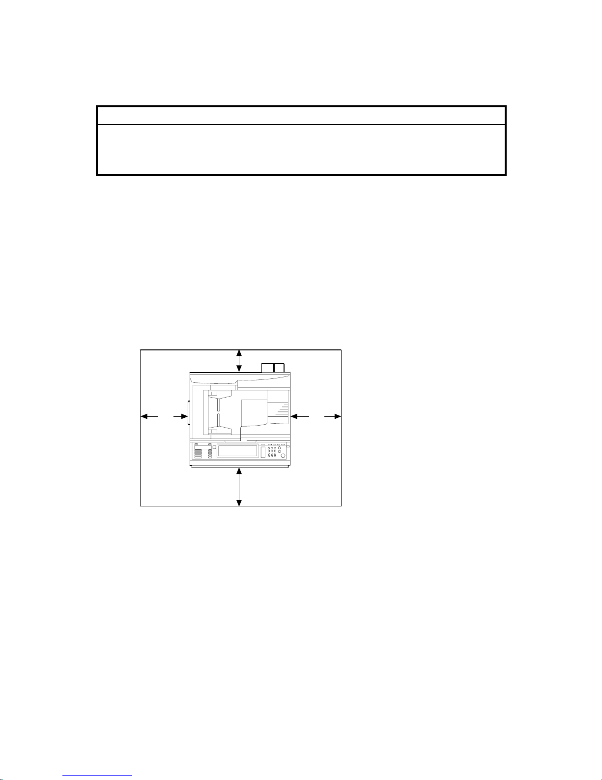
1.1.4 SPACE REQUIREMENTS
B156I501.WMF
A
: Over 100 mm (4")
B: Over 100 mm (4")
C: Over 550 mm (22")
D: Over 750 mm (29.6")
A C
B
D
10 February 2005 COPIER (B156/B220)
1-3
Installation
1.2 COPIER (B156/B220)
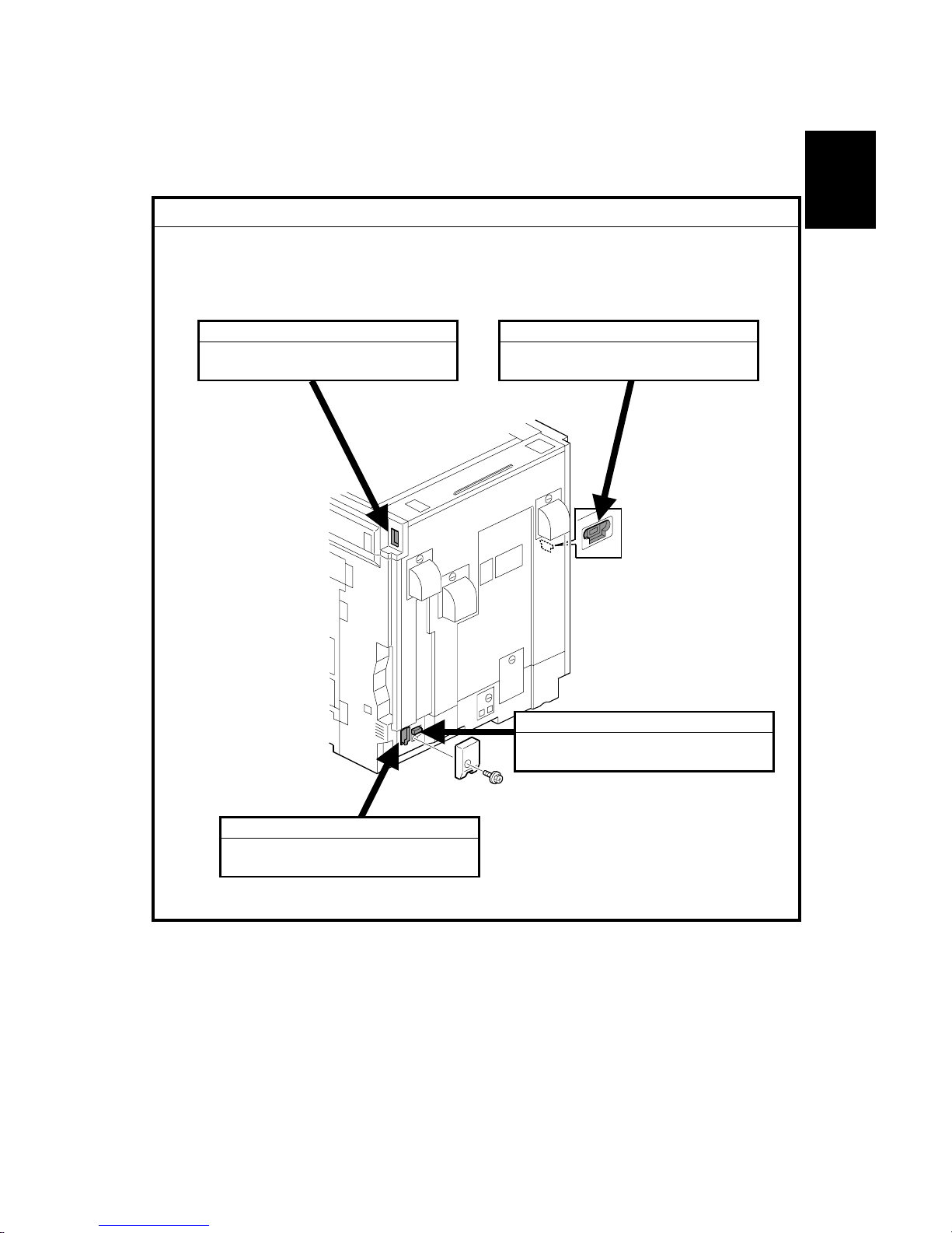
1.2.1 POWER SOCKETS FOR PERIPHERALS
!CAUTION
Rating voltage for peripherals.
Make sure to plug the cables into the correct sockets.
B156I502.WMF
1. ADF
1. Rating voltage output connector
for accessory Max. DC24 V
2. Finisher
1. Rating voltage output connector
for accessory Max. DC24 V
3. By-pass Tray
1. Rating voltage output connector
for accessory Max. DC24 V
4. Duplex Unit
1. Rating voltage output connector
for accessory Max. DC24 V
COPIER (B156/B220) 10 February 2005
1-4
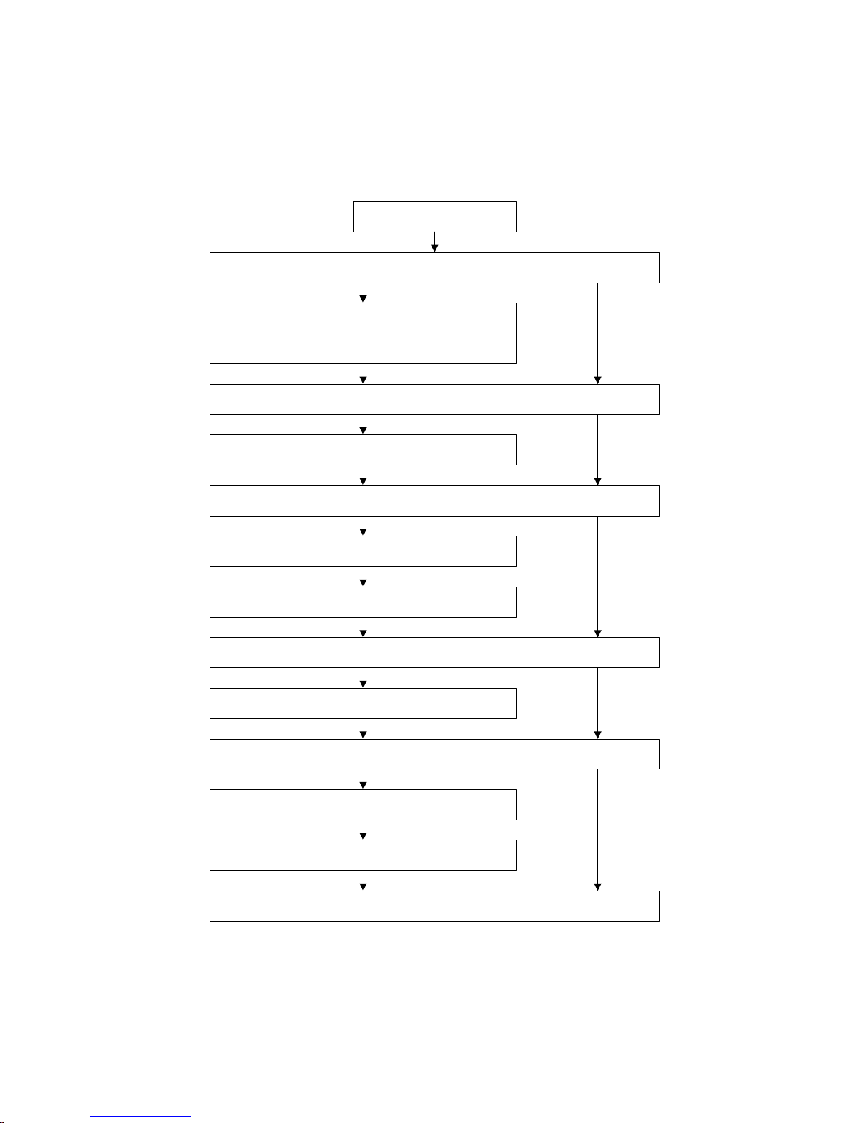
1.2.2 INSTALLATION FLOW CHART
The following flow chart shows how to install the optional units more efficiently.
Unpack the copier
Place the copier on the Paper Tray Unit or LCT
Install the Paper Tray Unit or LCT
Install the copier
Install the By-pass Tray
Yes No
Yes No
Install the Interchange Unit
Install the Duplex Unit and/or 1-bin Tray Unit
Yes No
Install the Shift Tray
Yes No
Install the Bridge Unit
Install the Finisher
Yes No
Does the user require the Paper Tray Unit, LCT, or Finisher?
Does the user require the By-pass Tray?
Install the ARDF or Platen Cover (if required)
Does the user require the Duplex Unit and/or 1-bin Tray Unit ?
Does the user require the Shift Tray?
Does the user require the Finisher?
Yes
B156I503.WMF

10 February 2005 COPIER (B156/B220)
1-5
Installation
1.2.3 ACCESSORY CHECK
Check the quantity and condition of the accessories in the box against the following
list:
No. Description Q’ty
1 Paper Tray Decal 1
2 Model Name Decal 1
3 NECR 1
4 Factory Data Sheet 1
5 Filter Duct 3
6 Filter 3
7 Caution Decal – Power/Paper 1
8 Decal – Copy prohibition 1
9 Manual Holder 1
10 Operating Instructions – System Setting 1
11 Operating Instructions – Copy Reference 1
12 Operating Instructions – Printer 2
13 Operating Instructions – Security 1
14 Instruction Procedure Sheet 1
15 Sheet – Notes for User 1
16 Screw for Manual Holder 2
17 Stamp 1
18 Cloth (ADF Standard version only) 1
19 Cloth Holder (ADF Standard version only) 1
COPIER (B156/B220) 10 February 2005
1-6
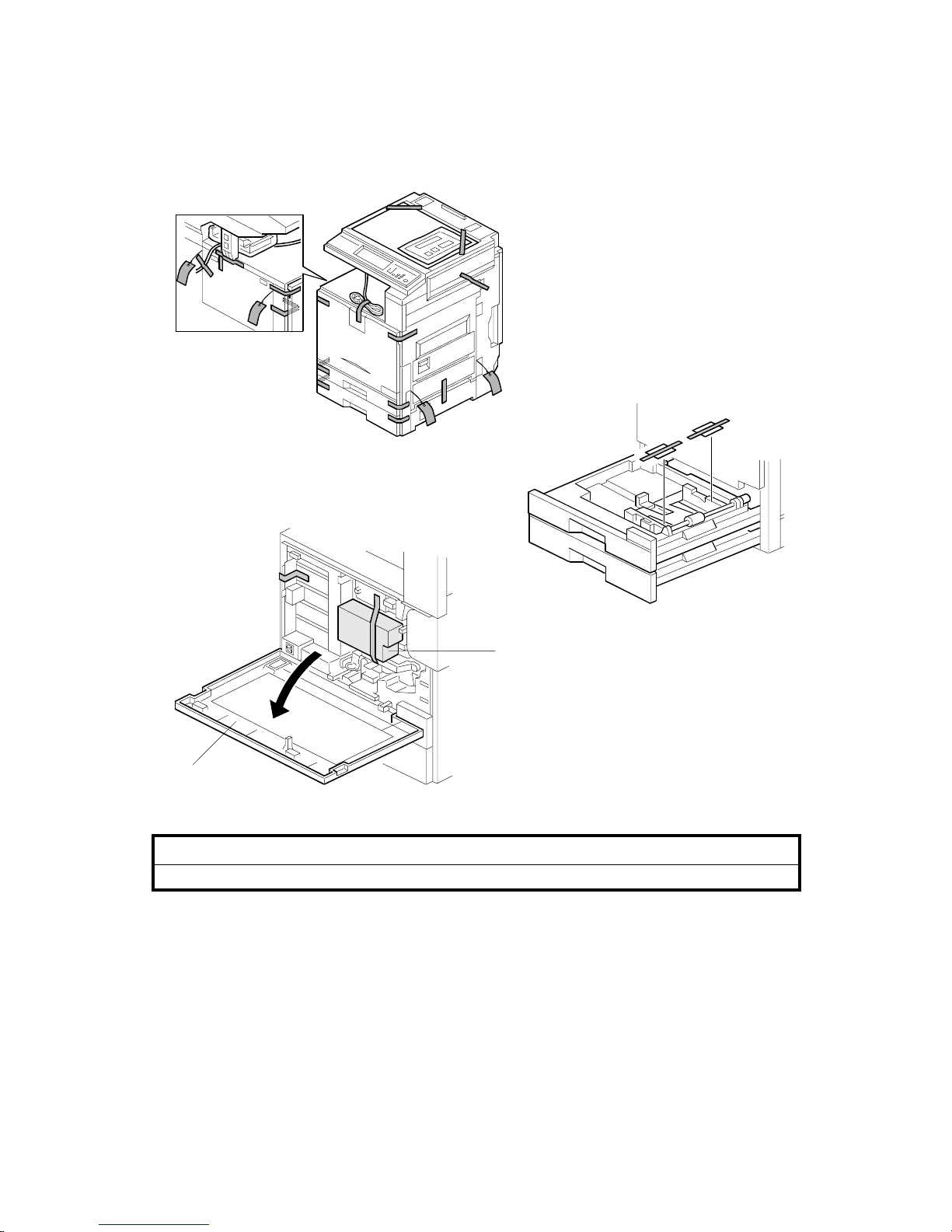
1.2.4 INSTALLATION PROCEDURE
!CAUTION
Unplug the machine power cord before starting the following procedure.
If the optional paper tray or the optional LCT will be installed at the same time,
place the copier on the paper tray unit or the LCT first, then install the copier and
the other options.
NOTE: Keep the shipping retainers after installing the machine. They will be
reused when the machine is moved to another location in the future.
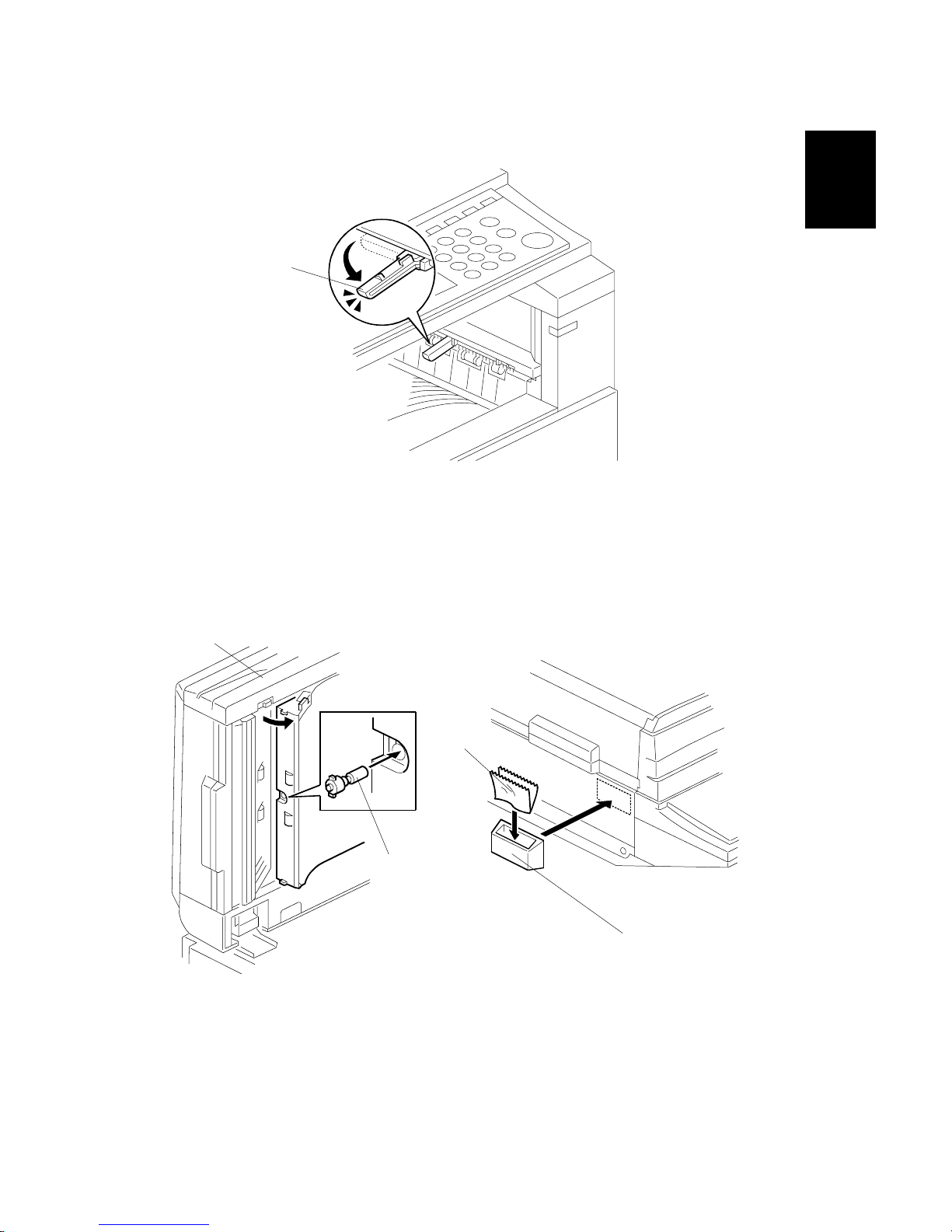
1. Remove the tapes.
2. Open the front cover [A] and remove the shipping retainer [B].
B156I504.WMF
B156I505.WMF
B156I506.WMF
[A]
[B]
10 February 2005 COPIER (B156/B220)
1-7
Installation
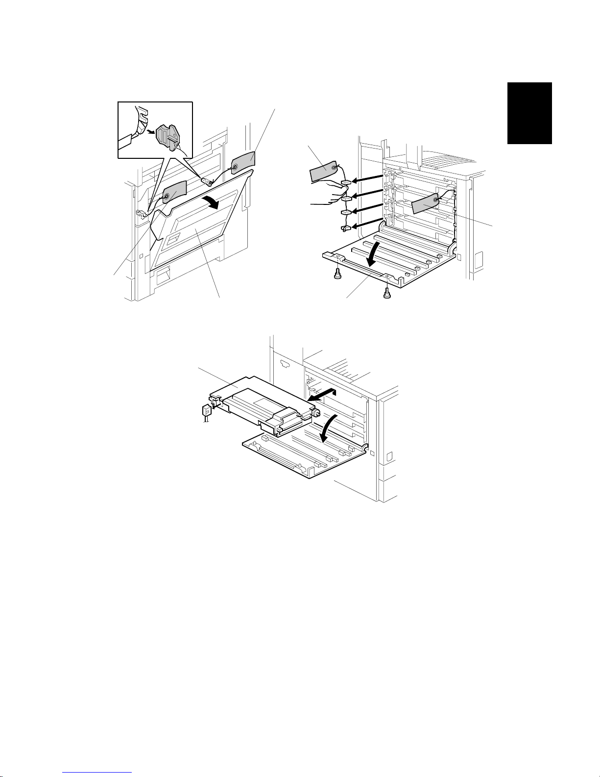
3. Open the right cover [A], and remove the red tags [B].
4. Open the left cover [C] (! x 2), and remove the red tags [D].
5. Pull out all development units [E] (" x 1 each).
B156I509.WMF
B156I507.WMF
B156I508.WMF
[C]
[D]
[D]
[A]
[B]
[B]
[E]
COPIER (B156/B220) 10 February 2005
1-8
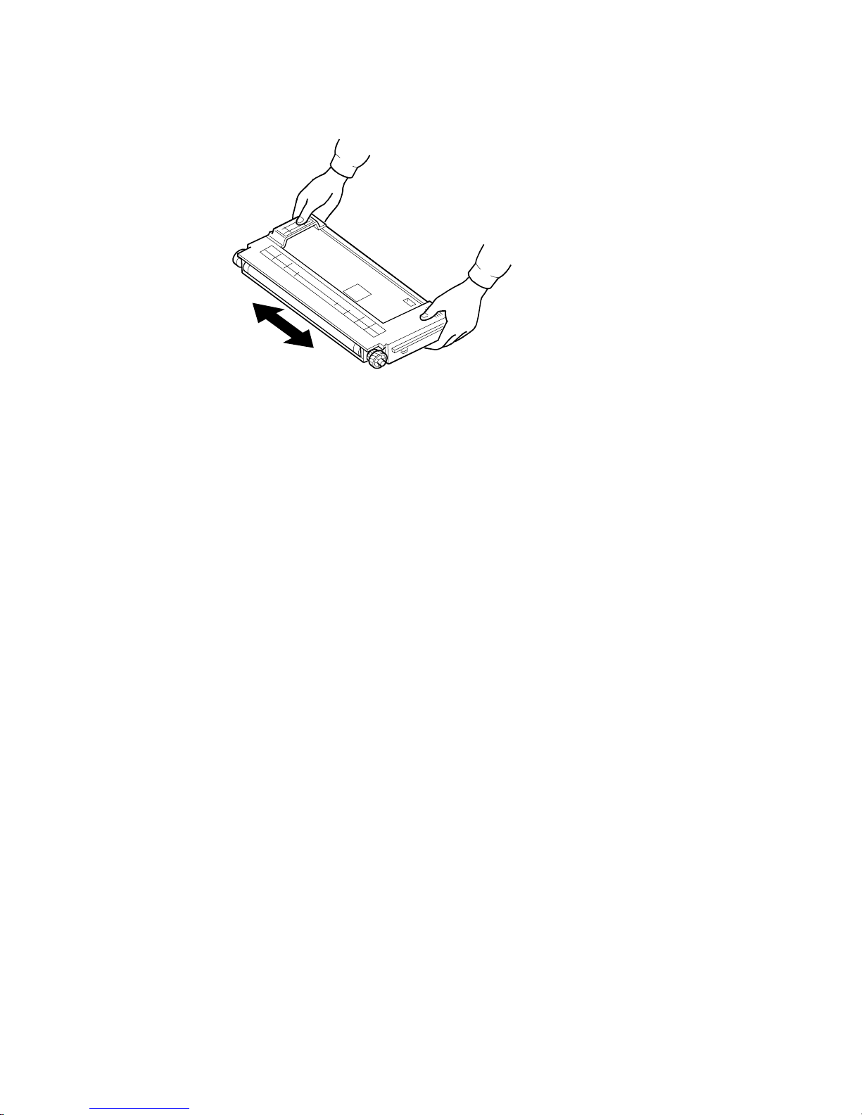
6. Keep the development unit level and shake the development unit about 10
times from side to side.
NOTE: 1) Do not touch the development roller or the development roller gear.
2) Use caution not to drop the cartridge or to damage it.
3) If the cartridge has not been shaken well, the machine takes a
longer time to initialize the development unit, or an error message or
SC350 is displayed. When either of them is displayed, turn the main
switch off and on.
B156I511.WMF
10 February 2005 COPIER (B156/B220)
1-9
Installation
7. Reinstall the development units, and close the left cover.
NOTE: A white line or band may appear on one end of the paper if a
development unit is incorrectly installed. To correct this, pull out the
development unit partially (about 30 mm) and slowly reinstall it.
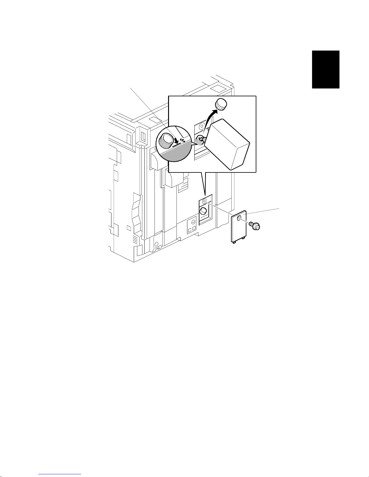
8. Remove the oil tank cover [A] (1 clip), and fill the oil tank to the maximum line.
NOTE: Do not fill the oil tank past the arrow [B].
B156I513.WMF
[A]
[B]
COPIER (B156/B220) 10 February 2005
1-10
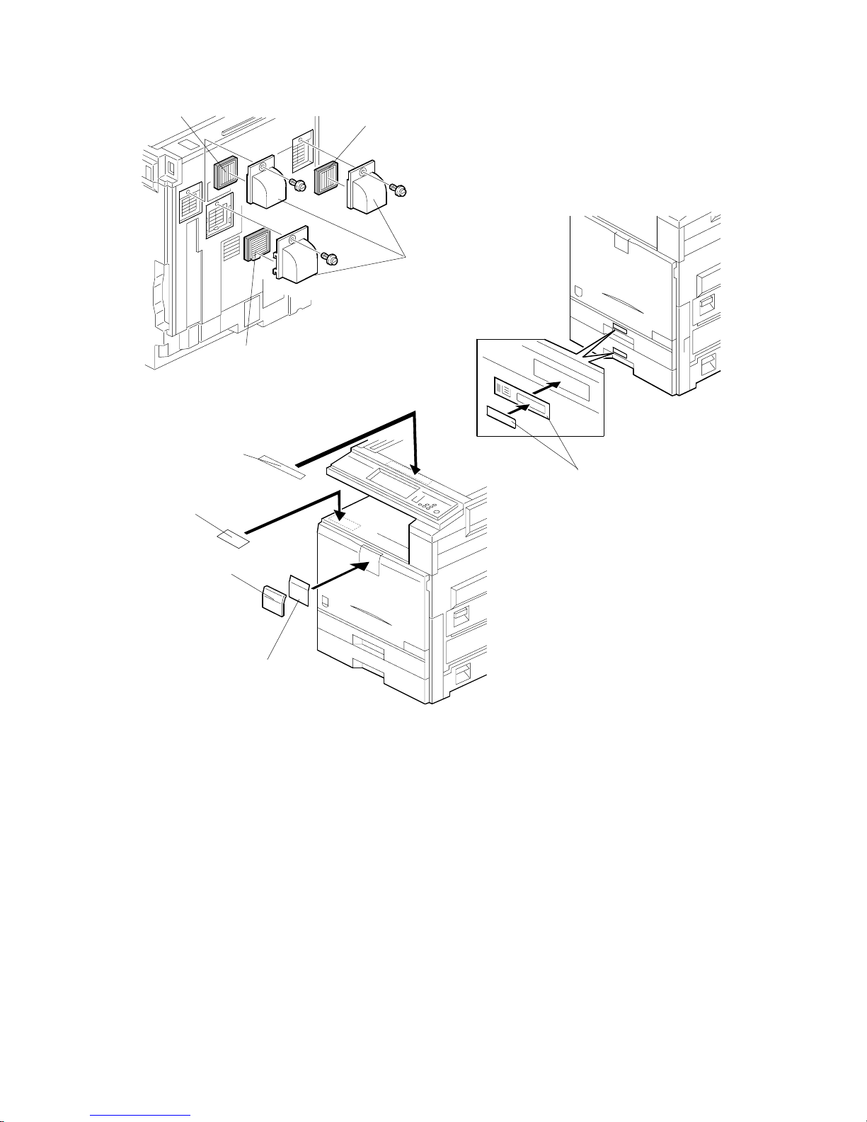
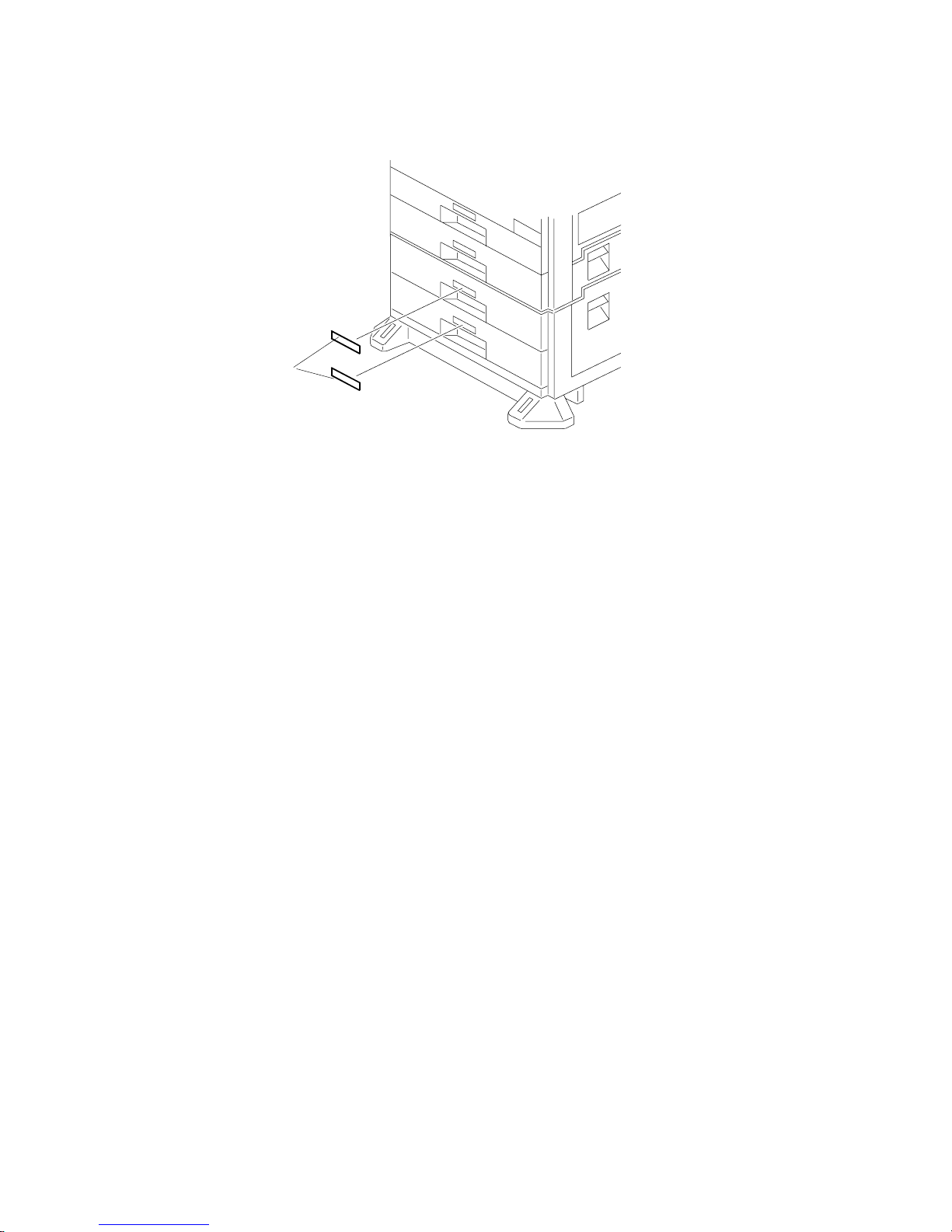
9. Install the filters [A] and ducts [B] as shown.
10. Attach the appropriate model name decal [C] with cover [D] to the front cover.
11. Attach the caution decal [E] to the tray. Attach the copy prohibition decal [F] to
the top.
12. Pull the paper tray out, and adjust the side guides and end guide to match the
paper size.
NOTE: To move the side guides, first pull out the tray fully, then push down the
green lock at the rear inside the tray.
13. Attach the appropriate paper tray number decals [J] to the paper trays.
NOTE: Paper tray number decals are also used for the optional paper tray or
the optional LCT. Keep any remaining decals for use with these
optional units.
B156I514.WMF
B156I516.WMF
B156I515.WMF
[A]
[B]
[A]
[A]
[J]
[C]
[D]
[E]
[F]
10 February 2005 COPIER (B156/B220)
1-11
Installation
14. If the optional bridge unit will not be installed: Swing the sensor feeler [A]
out.
15. Install the optional ARDF (EU model only) or the optional platen cover (see
ARDF Installation or Platen Cover Installation).
16. Install the stamp cartridge [B] if the ARDF [C] was installed.
17. Attach the cloth holder [D] to the left side of the scanner as shown. Then put
the cloth [E] in the cloth holder if the ARDF was installed.
B156I517.WMF
B502I006.WMF
B810I504.WMF
[A]
[B]
[C]
[D]
[E]
COPIER (B156/B220) 10 February 2005
1-12
18. Plug in the machine and turn the main power switch on. The machine
automatically performs the initialization procedure. After this has finished, the
Start button LED turns green.
19. Make copies of image samples (text, photo, and text/photo modes).
20. Perform Automatic Color Calibration (ACC).
NOTE: Since this machine has been subject to color adjustment using
Automatic Color Calibration (ACC) at the factory, there is no need to
make automatic color calibration again if the customer is satisfied with
the image sample. If the customer is not satisfied, do the following.
1) Print the ACC test pattern (UP mode – Maintenance – ACC – Start).
2) Place the printout on the exposure glass.
3) Place 10 sheets of white paper on top of the test chart. Then, close
the ADF or platen cover.
4) Press “Start Scanning” on the LCD panel. The machine performs the
ACC.
21. If you want to enable the Ethernet NIB function, set SP5-985-001 to “1: enable”.
If you want to enable the USB function, set SP5-985-002 to “1: enable”.
NOTE: The defaults are “0: disabled”.
22. Make sure that the sample image has been copied normally.
23. Remove the double-sided tape from
the manual holder. Then attach it [A] to
the left side of the copier (! x 2).
NOTE: When you install the 1,000-Sheet
Finisher (B408), attach the manual
holder a different location.
B156I532.WMF
[A]

10 February 2005 PAPER TRAY UNIT (B456)
1-13
Installation
1.3 PAPER TRAY UNIT (B456)
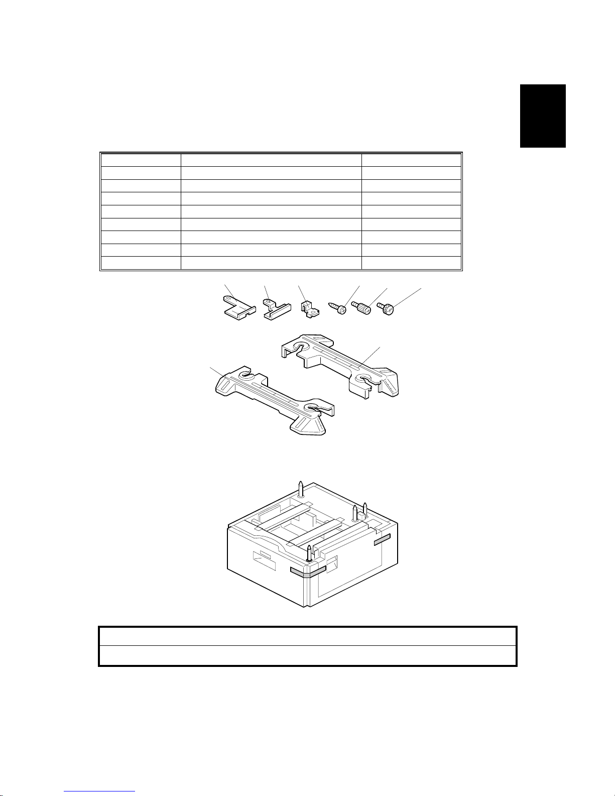
1.3.1 ACCESSORY CHECK
Check the quantity and condition of the accessories against the following list.
No. Description Q’ty
1 Right Stand Bracket 1
2 Left Stand Bracket 1
3 Securing Bracket 2
4 Front Stand 1
5 Rear Stand 1
6 Screw – M4x10 4
7 Knob Screw 2
8 Stepped Screw 2
1.3.2 INSTALLATION PROCEDURE
!CAUTION
Unplug the machine power cord before starting the following procedure.
1. Remove the strips of tape.
B456I001.WMF
B456I002.WMF
1 2 3
4 5
6 7 8
PAPER TRAY UNIT (B456) 10 February 2005
1-14
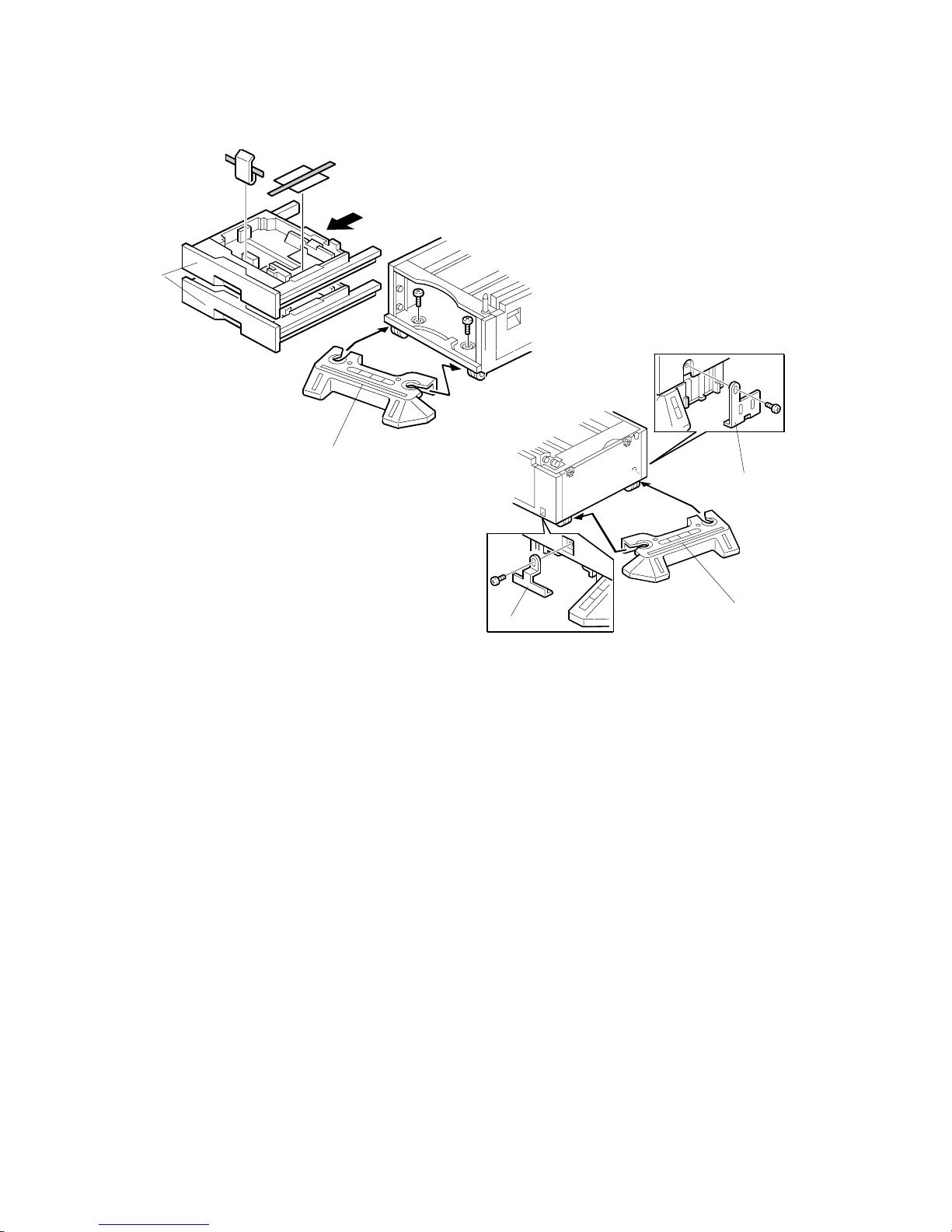
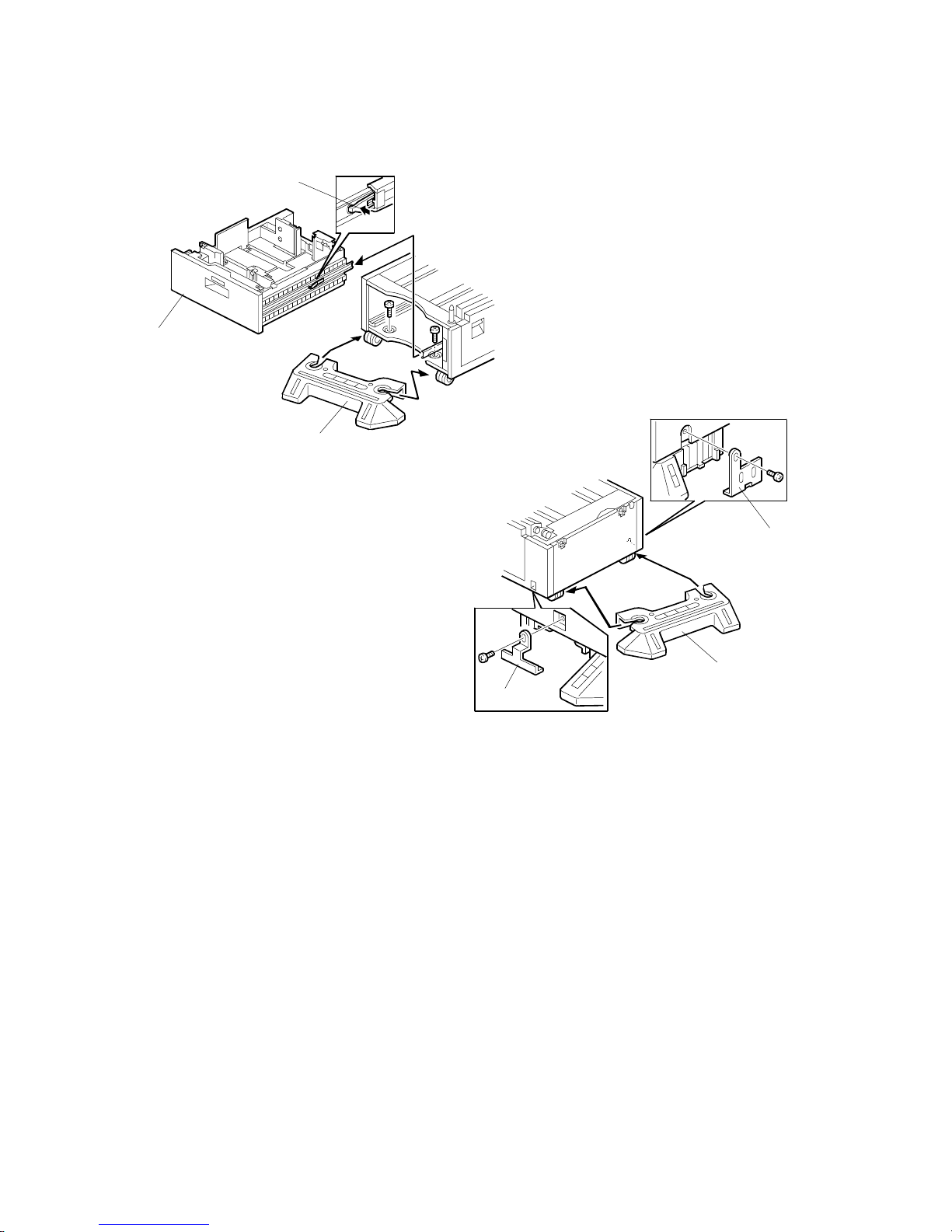
2. Remove the paper trays [A] from the paper tray unit and remove the shipping
retainers.
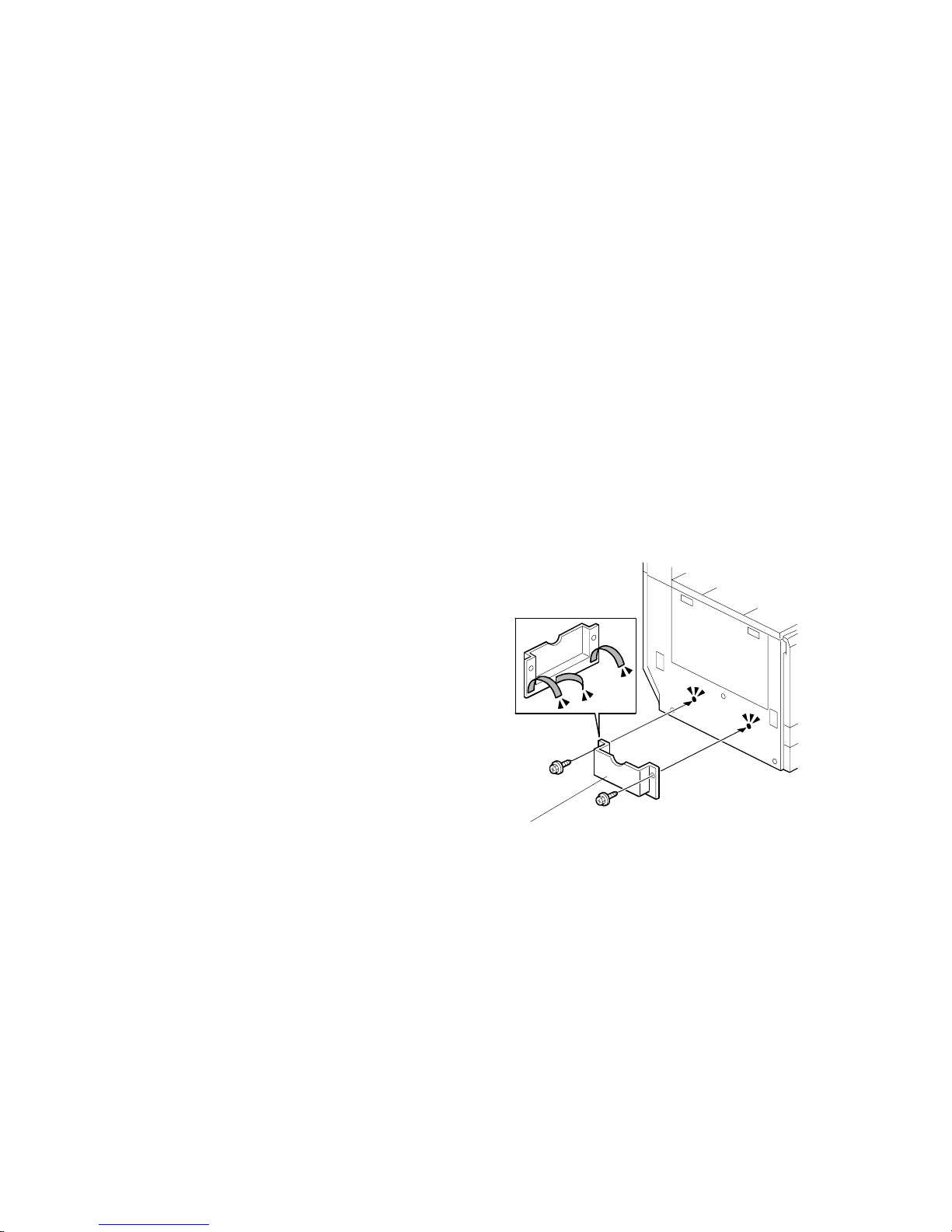
3. Install the front stand [B] (! x2).
4. Install the rear stand [C].
5. Attach the two stand brackets [D] (! x1 each).
B456I103.WMF
B456I104.WMF
[A]
[B]
[D]
[C]
[D]
10 February 2005 PAPER TRAY UNIT (B456)
1-15
Installation
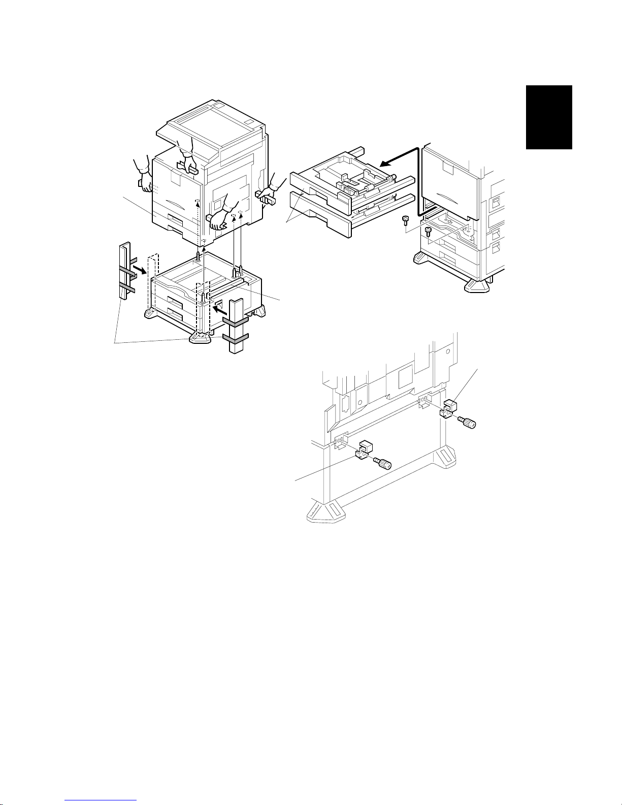
6. Attach the cardboard guides [A] to each side of the paper tray unit [B].
7. Set the copier [C] on the paper tray unit [B]. Use the cardboard guides.
8. Remove the cardboard guides from the paper tray unit.
9. Remove the paper trays [D] from the copier and secure the paper tray unit
(! x2).
10. Attach a securing bracket [E] to each side of the paper tray unit, as shown
(! x1 each).
B456I215.WMF
B456I106.WMF
B456I212.WMF
[A]
[B]
[D]
[E]
[E]
[C]
10 February 2005
1-16
11. Reinstall the paper trays and attach the appropriate paper tray number decal
[A] to the paper tray.
NOTE: The paper tray number decal is in the accessory box for the main
copier.
12. Load paper into the paper trays.
13. Turn on the main switch.
14. Check the machine’s operation and copy quality.
B456I004.WMF
[A]
10 February 2005 LCT (B457)
1-17
Installation
1.4 LCT (B457)
1.4.1 ACCESSORY CHECK
Check the quantity and condition of the accessories against the following list.
No. Description Q’ty
1 Right Stand Bracket 1
2 Left Stand Bracket 1
3 Securing Bracket 2
4 Front Stand 1
5 Rear Stand 1
6 Screw – M4x10 4
7 Knob Screw 2
8 Stepped Screw 2
1.4.2 INSTALLATION PROCEDURE
!CAUTION
Unplug the machine power cord before starting the following procedure.
1. Remove the strips of tape.
B457I007.WMF
B457I001.WMF
1
2 3
4
5
6
7 8
LCT (B457) 10 February 2005
1-18
2. While pressing the stopper [A] attached to the guide rail, pull out the large
capacity tray [B].
3. Install the front stand [C] (! x2).
4. Install the rear stand [D].
5. Attach the two stand brackets [E] (! x1 each).
B457I003.WMF
B457I104.WMF
[A]
[B]
[E]
[D]
[E]
[C]
 Loading...