

Page 1
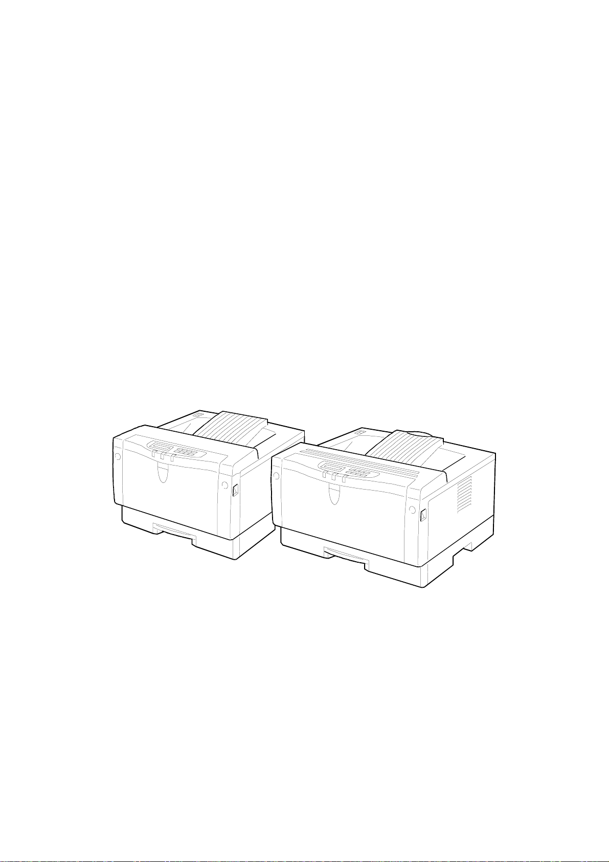
STINGER - P3/P4
SERVICE MANUAL
Subject to change
Ricoh Technical Service
March 12th 1999
Page 2

I
IMPORTANT SAFETY NOTICES
PREVENTION OF PHYSICAL INJURY
1. Before disassembling or assembling parts of the printer and peripherals,
make sure that the printer power cord is unplugged.
2. The wall outlet should be near the printer and easily accessible.
3. If any adjustment or operation check has to be made with exterior covers off
or open while the main switch is turned on, keep hands away from electrified
or mechanically driven components.
4. If a print job has started (the Data In LED has started blinking) before the
printer completes the warm-up or initializing period, keep hands away from
the mechanical and electrical components because the printer starts making
prints as soon as the warm-up period is completed.
5. The inside and the metal parts of the fusing unit become extremely hot while
the printer is operating. Avoid touching those components with your bare
hands.
HEALTH SAFETY CONDITIONS
Toner is non-toxic, but if you get it in your eyes by accident, it may cause
temporary eye discomfort. Try to remove with eye drops or flush with water as
first aid. If unsuccessful, get medical attention.
SAFETY AND ECOLOGICAL NOTES FOR DISPOSAL
1. Do not incinerate the toner cassettes. Toner dust may ignite suddenly when
exposed to an open flame.
2. Dispose of toner cassettes in accordance with local regulations. (This is a
non-toxic unit.)
3. Dispose of replaced parts in accordance with local regulations.
Page 3
LASER SAFETY
The Center for Devices and Radiological Health (CDRH) prohibits the repair of
laser-based optical units in the field. The optical housing unit can only be repaired
in a factory or at a location with the requisite equipment. The laser subsystem is
replaceable in the field by a qualified Customer Engineer. The laser chassis is not
repairable in the field. Customer engineers are therefore directed to return all
chassis and laser subsystems to the factory or service depot when replacement of
the optical subsystem is required.
WARNING
I
Use of controls, or adjustment, or performance of procedures other than
those specified in this manual may result in hazardous radiation exposure.
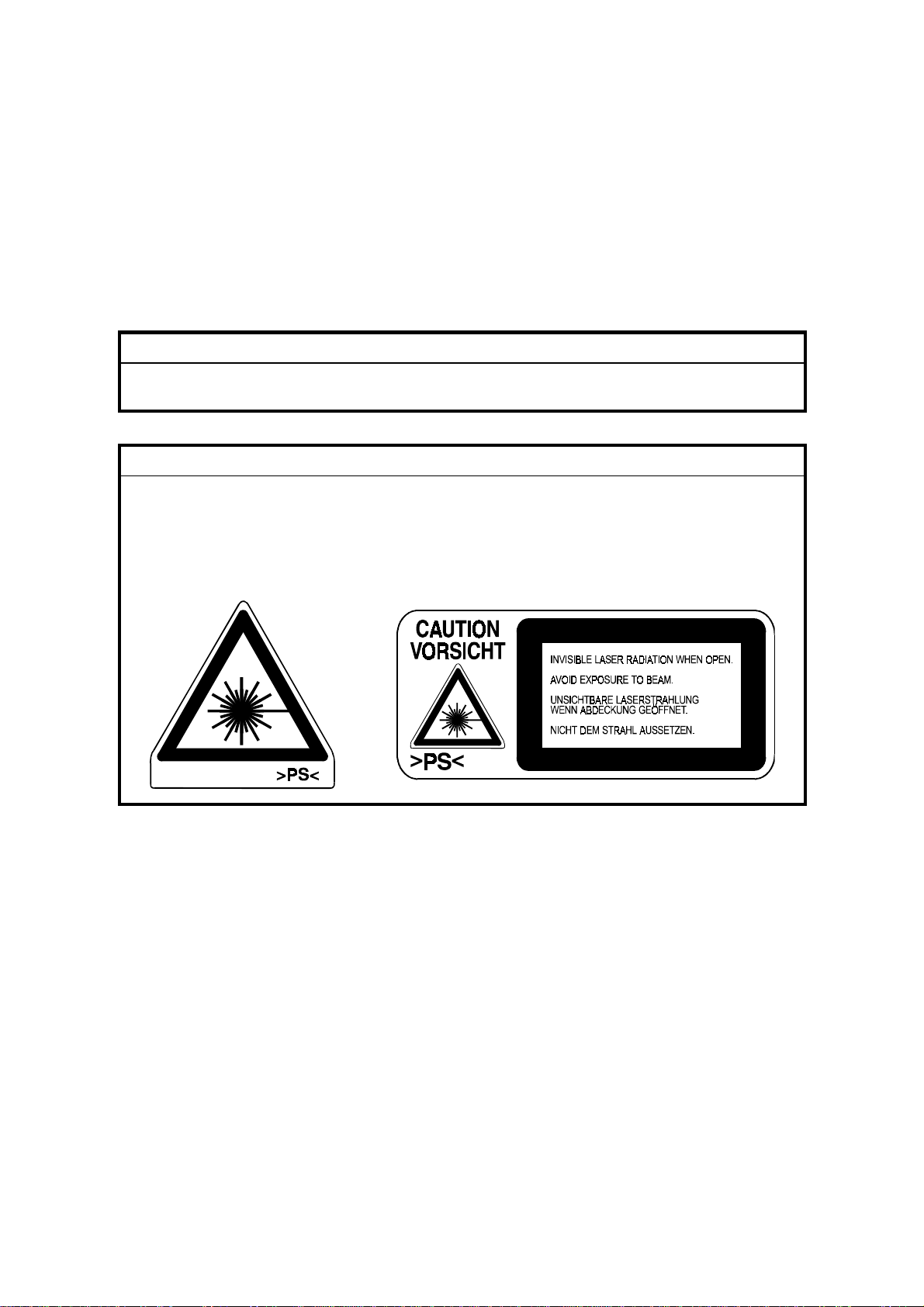
WARNING FOR LASER UNIT
I
WARNING: Turn off the main switch before attempting any of the
procedures in the Laser Unit section. Laser beams can
seriously damage your eyes.
CAUTION MARKING:
Page 4

TABLE OF CONTENTS
1. OVERALL MACH INE INFORMATION........................................1-1
1.1 SPECIFICATIONS.................................................................................... 1-1
1.2 MACHINE CONFIGURATION.................................................................. 1-5
1.3 PAPER PATH........................................................................................... 1-6
1.4 MECHANICAL COMPONENT LAYOUT................................................... 1-7
1.5 ELECTRICAL COMPONENT LAYOUT.................................................... 1-8
1.6 ELECTRICAL COMPONENT DESCRIPTIONS...................................... 1-10
1.7 PRINTING PROCESS............................................................................ 1-12
1.8 BOARD STRUCTURE............................................................................ 1-14
1.8.1 OVERVIEW ................................................................................... 1-14
1.8.2 MAJOR COMPONENTS................................................................ 1-15
1.9 COMPARISON....................................................................................... 1-16
2. DETAILED SECTION DESCRIPTIONS.......................................2-1
2.1 PRINTING................................................................................................. 2-1
2.1.1 IMAGE DATA PATH........................................................................ 2-1
2.1.2 PRINTER CONTROL BOARD......................................................... 2-2
2.1.3 IMAGE DATA PROCESSIING......................................................... 2-3
2.1.4 HOST INTERFACE.......................................................................... 2-4
2.2 LASER EXPOSURE................................................................................. 2-5
2.2.1 OVERVIEW ..................................................................................... 2-5
2.2.2 OPTICAL PATH............................................................................... 2-6
2.2.3 AUTO POWER CONTROL (APC)................................................... 2-8
2.2.4 LD SAFETY SWITCH...................................................................... 2-9
2.3 TONER CARTRIDGE............................................................................. 2-10
2.3.1 OVERVIEW ................................................................................... 2-10
2.3.2 DRIVE............................................................................................ 2-11
2.3.3 DRUM CHARGE............................................................................ 2-12
2.3.4 DEVELOPMENT............................................................................ 2-13
2.3.5 DRUM CLEANING......................................................................... 2-15
2.4 IMAGE TRANSFER AND PAPER SEPARATION.................................. 2-16
2.4.1 OVERVIEW ................................................................................... 2-16
2.4.2 TRANSFER ROLLER CLEANING................................................. 2-17
2.5 PAPER FEED......................................................................................... 2-18
2.5.1 OVERVIEW ................................................................................... 2-18
2.5.2 PAPER TRAY................................................................................ 2-20
2.5.3 BY-PASS TRAY............................................................................. 2-25
2.5.4 PAPER REGISTRATION............................................................... 2-27
2.6 IMAGE FUSING...................................................................................... 2-29
2.6.1 OVERVIEW ................................................................................... 2-29
2.6.2 FUSING......................................................................................... 2-30
2.6.3 FUSING UNIT DRIVE.................................................................... 2-30
2.6.4 PRESSURE ROLLER/PAPER EXIT.............................................. 2-31
i
Page 5

2.6.5 FUSING UNIT DRIVE RELEASE................................................... 2-31
2.6.6 NEW FUSING UNIT DETECTION (STINGER - P3 ONLY)............ 2-32
2.6.7 FUSING TEMPERATURE CONTROL........................................... 2-33
2.6.8 OVERHEAT PROTECTION........................................................... 2-35
2.6.9 ENERGY SAVER MODE............................................................... 2-36
2.7 COVER OPEN DETECTION.................................................................. 2-37
2.7.1 FRONT COVER LOCK.................................................................. 2-37
2.7.2 FRONT COVER SAFETY SWITCH............................................... 2-37
2.7.3 REMOVING THE FUSING UNIT................................................... 2-38
2.8 ENGINE CONTROL BOARD.................................................................. 2-39
2.8.1 PCB LAYOUT................................................................................ 2-39
2.8.2 DEVICES....................................................................................... 2-40
2.8.3 STRUCTURE................................................................................. 2-41
2.8.4 CONNECTION TO THE ECB........................................................ 2-42
2.9 SIGNAL TABLE...................................................................................... 2-44
2.10 PRINTER CONTROL BOARD.............................................................. 2-47
2.10.1 PCB LAYOUT.............................................................................. 2-47
2.10.2 DEVICES..................................................................................... 2-48
3. INSTALLA TION...........................................................................3-1
3.1 INSTALLATION REQUIREMENTS .......................................................... 3-1
3.1.1 ENVIRONMENT .............................................................................. 3-1
3.1.2 POWER REQUIREMENTS.............................................................. 3-1
3.2 PRINTER INSTALLATION........................................................................ 3-2
3.3 PAPER FEED UNIT INSTALLATION....................................................... 3-2
3.4 ENVELOPE FEEDER INSTALLATION.....................................................3-2
3.5 HARD DISK INSTALLATION.................................................................... 3-2
3.6 MEMORY UNIT INSTALLATION.............................................................. 3-2
3.7 NETWORK INTERFACE BOARD INSTALLATION.................................. 3-2
3.8 CHECKING THE CONNECTIONS........................................................... 3-3
3.8.1 CONNECTION BETWEEN MAIN PRINTER CONTROL BOARD
(AND RELATED OPTIONS: HDD, RAM SIMM, NIC) AND
OPTIONAL HDD & PERIPHERALS................................................. 3-3
3.8.2 CONNECTION BETWEEN PRINTER CONTROL BOARD AND
NETWORK INTERFACE BOARD.................................................... 3-6
3.8.3 PRINTING THE NETWORK INTERFACE BOARD
CONFIGURATION SHEET.............................................................. 3-6
4. SERVICE PROCEDURES AND TABLES................................... 4-1
4.1 OVERVIEW .............................................................................................. 4-1
4.2 SERVICE PROGRAM MODE................................................................... 4-2
4.2.1 ENABLING AND DISABLING SERVICE PROGRAM MODE.......... 4-2
4.2.2 SERVICE PROGRAM MODE MENU TREE.................................... 4-3
4.2.3 SERVICE MODE MENU TABLE...................................................... 4-5
4.2.4 PRINT LOG...................................................................................... 4-9
4.2.5 PRINTER ID................................................................................... 4-13
4.3 IC CARD BOOT SERVICE MODE ......................................................... 4-15
ii
Page 6

4.3.1 OVERVIEW ................................................................................... 4-15
4.3.2 ENABLING AND DISABLING IC CARD BOOT SERVICE
MODE............................................................................................ 4-15
4.3.3 IC CARD BOOT SERVICE MODE TREE...................................... 4-16
4.3.4 SERVICE MENU TABLE............................................................... 4-17
4.4 EEPROM AND NVRAM RESET PROCEDURES................................... 4-18
4.5 DOWNLOADING NEW CONTROLLER SOFTWARE ............................ 4-19
4.5.1 OVERVIEW ................................................................................... 4-19
4.5.2 DOWNLOADING NEW FIRMWARE FROM AN IC CARD............. 4-20
4.6 USER MENU.......................................................................................... 4-23
4.7 ECB TEST PATTERN............................................................................. 4-24
4.8 DIAGNOSTIC TEST MODES................................................................. 4-25
4.8.1 OVERVIEW ................................................................................... 4-25
4.8.2 POWER-UP DIAGNOSTIC MODE................................................ 4-25
4.8.3 DETAILED DIAGNOSTIC MODE.................................................. 4-26
4.8.4 DIAGNOSTIC TEST DETAILS....................................................... 4-27
5. PREVENTIVE MAINTENANCE...................................................5-1
5.1 PREVENTIVE MAINTENANCE SCHEDULE............................................ 5-1
6. REPLACEMENT A N D ADJUSTMENT........................................ 6-1
6.1 COVERS................................................................................................... 6-1
6.1.1 EXTERIOR COVER REMOVAL...................................................... 6-1
6.1.2 FRONT COVER REMOVAL............................................................ 6-2
6.1.3 CONTROL BOARD COVER REMOVAL ......................................... 6-3
6.2 FUSING UNIT........................................................................................... 6-4
6.2.1 FUSING UNIT REPLACEMENT...................................................... 6-4
6.2.2 HOT ROLLER AND FUSING LAMP REPLACEMENT .................... 6-5
6.2.3 PRESSURE ROLLER REPLACEMENT.......................................... 6-7
6.2.4 FUSING THERMOFUSE REPLACEMENT ..................................... 6-8
6.2.5 FUSING DRAWER CONNECTOR REPLACEMENT....................... 6-9
6.3 TRANSFER ROLLER............................................................................. 6-10
6.3.1 TRANSFER ROLLER REPLACEMENT ........................................ 6-10
6.4 PAPER FEED......................................................................................... 6-11
6.4.1 BY-PASS TRAY REMOVAL.......................................................... 6-11
6.4.2 BY-PASS FEED ROLLER REPLACEMENT.................................. 6-12
6.4.3 PAPER FEED ROLLER REPLACEMENT..................................... 6-15
6.4.4 RELAY ROLLER REPLACEMENT (STINGER - P4 ONLY)........... 6-17
6.4.5 FRICTION PAD REPLACEMENT.................................................. 6-18
6.4.6 TRAY PAPER FEED CLUTCH REPLACEMENT.......................... 6-19
6.5 LASER UNIT........................................................................................... 6-20
6.5.1 CAUTION DECAL LOCATIONS.................................................... 6-20
6.5.2 LASER UNIT/SHIELD GLASS REPLACEMENT........................... 6-21
6.5.3 LD UNIT/LASER SYNCHRONIZATION DETECTOR
REPLACEMENT............................................................................ 6-22
6.5.4 POLYGONAL MIRROR MOTOR REPLACEMENT....................... 6-23
6.5.5 LD UNIT/POLYGONAL MIRROR MOTOR REPLACEMENT........ 6-24
iii
Page 7

6.6 OTHERS................................................................................................. 6-25
6.6.1 TONER NEAR-END SENSOR REPLACEMENT........................... 6-25
6.6.2 MAIN MOTOR/GEAR BOX REMOVAL ......................................... 6-26
6.6.3 ENGINE CONTROL BOARD REPLACEMENT............................. 6-27
6.6.4 PRINTER CONTROL BOARD REPLACEMENT........................... 6-28
6.6.5 HIGH VOLTAGE SUPPLY BOARD............................................... 6-29
6.6.6 POWER SUPPLY UNIT REPLACEMENT..................................... 6-30
6.7 PRINT REGISTRATION ADJUSTMENT................................................ 6-31
7. TROUBLESHOOTING.................................................................7-1
7.1 OPERATOR ERRORS ............................................................................. 7-1
7.2 PRINTER ENGINE SC CODES................................................................ 7-6
7.3 DIAGNOSTIC ERROR CODES................................................................ 7-9
7.3.1 DIAGNOSTIC ERROR CODE TABLE............................................. 7-9
7.4 ELECTRICAL COMPONENT DEFECTS................................................ 7-17
7.4.1 SENSORS..................................................................................... 7-17
7.4.2 SWITCHES.................................................................................... 7-17
7.4.3 FUSES........................................................................................... 7-17
iv
Page 8

OPTION
ENVELOPE FEEDER (Machine Code: G913)
1. OVERALL INFORMATION................................................... G913-1
1.1 SPECIFICATIONS..............................................................................G913-1
1.2 MECHANICAL COMPONENT LAYOUT.............................................G913-1
2. DETAILED SECTION DESCRIPTIONS................................ G913-2
2.1 PAPER LIFT.......................................................................................G913-2
3. INSTALLA TION.................................................................... G913-3
4. REPLACEMENT AND ADJUSTMENT................................. G913-4
4.1 FRICTION PAD REPLACEMENT.......................................................G913-4
PAPER FEED UNIT (Machine Code: G914)
1. OVERALL MACH INE INFORMATION................................. G914-1
1.1 SPECIFICATIONS..............................................................................G914-1
1.1.1 STINGER - P3...........................................................................G914-1
1.1.2 STINGER - P4...........................................................................G914-1
1.2 MECHANICAL COMPONENT LAYOUT.............................................G914-2
1.3 ELECTRICAL COMPONENT LAYOUT..............................................G914-3
1.4 ELECTRICAL COMPONENT DESCRIPTION....................................G914-4
2. DETAILED SECTION DESCRIPTIONS................................ G914-5
2.1 PAPER SIZE DETECTION.................................................................G914-5
2.2 PAPER LIFT.......................................................................................G914-5
2.3 PAPER END DETECTION .................................................................G914-5
2.4 PAPER NEAR END DETECTION ......................................................G914-5
2.5 PAPER FEED.....................................................................................G914-6
3. INSTALLA TION.................................................................... G914-8
4. REPLACEMENT AND ADJUSTMENT................................. G914-9
4.1 PAPER FEED UNIT (OPTION FOR STINGER - P3)..........................G914-9
4.1.1 PAPER FEED ASSEMBLY REMOVAL .....................................G914-9
4.1.2 DRIVE ROLLER REPLACEMENT...........................................G914-10
4.1.3 PAPER FEED MOTOR REPLACEMENT................................G914-11
v
Page 9

4.1.4 PAPER FEED CLUTCH REMOVAL........................................G914-12
4.1.5 PAPER FEED UNIT BOARD/PAPER SIZE SWITCH
REPLACEMENT......................................................................G914-13
4.2 PAPER FEED UNIT (OPTION FOR STINGER - P4)........................ G914-14
4.2.1 PAPER FEED ROLLER/PAPER FEED CLUTCH
REPLACEMENT......................................................................G914-14
4.2.2 PAPER DRIVE ROLLER REPLACEMENT..............................G914-15
4.2.3 DRIVE ROLLER IDLER/FRICTION PAD REPLACEMENT.....G914-16
4.2.4 PAPER FEED MOTOR/PAPER FEED UNIT BOARD
REPLACEMENT......................................................................G914-17
NETWORK INTERFACE BOARD (Machine Code: G919)
1. OVERALL MACH INE INFORMATION................................. G917-1
1.1 SPECIFICATIONS..............................................................................G917-1
2. INSTALLATION PROCEDURE............................................ G917-2
2.1 HARDWARE INSTALLATION ............................................................G917-2
2.1.1 SERIAL NUMBER AND MAC ADDRESS..................................G917-2
2.1.2 STATUS SHEET........................................................................G917-2
2.2 PROGRAMMING NETWORK/PROTOCOL PARAMETERS..............G917-3
2.2.1 IPX NETWORK..........................................................................G917-3
2.2.2 TCP/IP NETWORK....................................................................G917-4
2.2.3 ETHERTALK (APPLETALK) NETWORK...................................G917-5
2.3 SETUP FOR VARIOUS NETWORK TYPES...................................... G917-6
2.3.1 PEER-TO-PEER NETWORK.....................................................G917-6
2.3.2 NOVELL NETWARE NETWORK...............................................G917-7
2.3.3 TCP/IP NETWORK....................................................................G917-7
3. SERVICE TABLES AND PROCEDURES ............................ G917-8
3.1 FACTORY RESET (NVRAM CLEAR).................................................G917-8
3.2 FLASH ROM UPDATE.......................................................................G917-9
3.2.1 INTRODUCTION .......................................................................G917-9
3.2.2 FLASHUP UTILITY (FOR NOVELL IPX NETWORKS)............G917-10
3.2.3 FTPDL UTILITY (FOR TCP/IP NETWORKS)..........................G917-13
4. TROUBLESHOOTIN G........................................................ G917-16
4.1 LED INDICATIONS...........................................................................G917-16
vi
Page 10

APPENDIX
1. DOWNLOADING CONTROLLER FIRMWARE...........APPENDIX-1
1.1 OVERVIEW .............................................................................. APPENDIX-1
1.1.1 IC CARD (FLASH CARD)................................................APPENDIX-1
1.1.2 PC, VIA PARALLEL PORT.............................................. APPENDIX-2
1.1.3 DIMM............................................................................... APPENDIX-2
1.1.4 RELEASING NEW CONTROLLER FIRMWARE............. APPENDIX-3
1.2 SERVICE TOOLS..................................................................... APPENDIX-4
1.2.1 OPERATION PANEL....................................................... APPENDIX-4
1.2.2 SERVICE TOOL MENUS ................................................ APPENDIX-5
1.2.3 STINGER SERVICE UTILITY (SSU)...............................APPENDIX-7
1.3 USING AN IC CARD................................................................. APPENDIX-8
1.3.1 PREPARING THE IC CARD............................................ APPENDIX-8
1.3.2 DOWNLOADING FROM THE IC CARD TO
THE PRINTER............................................................... APPENDIX-13
1.4 USING A DIMM ...................................................................... APPENDIX-14
1.4.1 PREPARING THE DIMM............................................... APPENDIX-14
1.4.2 DOWNLOADING FROM THE DIMM TO
THE PRINTER............................................................... APPENDIX-19
1.5 COPYING FROM A PC DIRECTLY........................................ APPENDIX-20
1.5.1 PREPARATION............................................................. APPENDIX-20
1.5.2 DOWNLOADING TO THE FLASH MEMORY................ APPENDIX-22
1.6 SSU TROUBLESHOOTING ................................................... APPENDIX-26
vii
Page 11

12 March 1999 SPECIFICATIONS
1. OVERALL MACHINE INFORMATION
1.1 SPECIFICATIONS
Configuration: Desktop
Print Process: Laser beam scanning & electrophotographic printing
Monocomponent toner development
Printing Speed
(600 dpi):
First Print Speed: Stinger - P3:
Resolution: True 1,200 x 1,200 dpi (available for PCL6 or PostScript)
Printer Language PCL6/PCL5e
Stinger - P3:
Maximum 20 pages per minute (A4/LT LEF)
Stinger - P4:
Maximum 14 pages per minute (A4/LT SEF)
5.5 s or less (A4/LT - LEF, standard tray)
Stinger - P4:
6.5 s or less (A4/LT - SEF, standard tray)
600 x 600 dpi
300 x 300 dpi (simulated by doubling pixel width and
height at 600 dpi resolution)
Compatible with Laser Jet 5N driver and printer.
Windows 3.1x/95/98, Windows NT4.0 drivers available.
PostScript Level II
Windows 95/98, Windows NT4.0, and Macintosh (OS
7.5 or later) PPDs are available.
Overall
Information
Printer Fonts: PCL6
35 Intellifonts
10 True Type fonts
1 Bitmap font
PS2
35 Adobe type 1 fonts
Printer Interface: Bi-directional IEEE1284 parallel x 1 (Standard)
Ethernet (100 Base-TX/10 Base-T for TCP/IP, IPX/SPX,
EtherTalk)
RS232C interface (Optional)
1-1
Page 12

SPECIFICATIONS 12 March 1999
Printing Paper Size: Stinger - P3:
Maximum A3/11" x 17"
Minimum A5 LEF - Standard Tray
B6 SEF - By-pass Tray
A5 LEF - Optional PFU
Custom paper size (PCL 6/PS): By-pass Tray
11.69" x 17" ~ 3.88" x 5.83"
(297 x 431.8 ~ 98.4 x 148 mm)
Envelope: By-pass & Envelope Feeder
Com#10, C6, DL, Monarch
Stinger - P4:
Maximum A4/LG (only A4/LT for Standard Tray)
Minimum A4/LT – Standard Tray
B6 SEF - By-pass Tray
A5 LEF - Optional PFU
Custom paper size (PCL 6/PS): By-pass Tray
8.5" x 14" ~ 3.88" x 5.83"
(216 x 355.6 ~ 98.4 x 148 mm)
Envelope: By-pass & Envelope Feeder
Com#10, C6, DL, Monarch
Printing Paper Weight: Paper tray: 60 ~ 106 g/m2, 16 ~ 28 lb
By-pass: 60 ~ 162 g/m2, 16 ~ 43 lb
Power Source: Stinger - P3:
120 V, 60 Hz: More than 8.0 A (for North America)
220 V ~ 240 V, 50/60 Hz: More than 8.0 A (for Europe)
Stinger - P4:
120 V, 60 Hz: More than 6.0 A (for North America)
220 V ~ 240 V, 50/60 Hz: More than 5.0 A (for Europe)
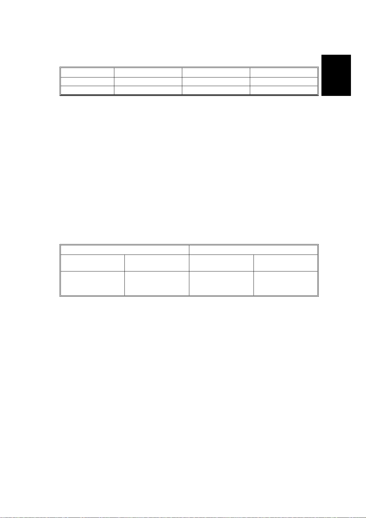
Power Consumption:
Stinger - P3 Stinger - P4
Maximum 795 W or less 600 W or less
Printing 480 W or less 380 W or less
Energy Saver 30 W or less 30 W or less
Noise Emission (All Options Installed):
Stinger - P3 Stinger - P4
Sound Power Level
Printing 64 dB or less 59 dB or less
Stand-by 48 dB or less 48 dB or less
NOTE:
The above measurements were made in accordance with ISO 9296 at
the operator position.
1-2
Page 13
12 March 1999 SPECIFICATIONS
Dimensions (Printer only):
Width Depth Height
Stinger - P3 450 mm (17.7") 420 mm (16.6") 270 mm (10.6")
Stinger - P4 360 mm (14.2") 420 mm (16.6") 270 mm (10.6")
Weight: Stinger - P3: Less than 15 kg (33 Ib.)
Stinger - P4: Less than 12 kg (27 Ib.)
Overall
Information
Warm-up Time
Less than 39 seconds: 23°C
Energy Saver Mode 30 min. is the standard setting; it can be changed with the
Job Control menu
Print Paper Capacity: Standard Tray: 250 sheets
By-pass Tray: 100 sheets
10 envelopes (Stinger - P3)
5 envelopes (Stinger - P4)
Optional Paper Feed Unit: 500 sheets x 2 (Stinger - P3)
500 sheets x 1 (Stinger - P4)
Optional Envelope Feeder: 60 envelopes
Memory:
Standard 8 MB, up to 40 MB with optional SIMM.
Toner Cartridge Information:
Stinger - P3 Stinger - P4
Pre-set
Toner Cartridge
Average
3,000 pages/crtg.;
200g
Measurement Conditions:
Commercial
Toner Cartridge
Average
14,000 pages/crtg.;
750g
1) 5% test pattern
Pre-set
Toner Cartridge
Average
3,000 pages/crtg.;
200g
Commercial
Toner Cartridge
Average
8,000 pages/crtg.;
430g
2) A4 paper
3) LEF for Stinge r - P3, SEF for Stinger - P4
4) Continuous printing
Optional Equipment:
·
A3/DLT paper feed unit (unique for Stinger - P3)
·
A4/LT paper feed unit (unique for Stinger - P3)
·
Paper feed unit (unique for Stinger - P4)
·
Envelope feeder (unique for Stinger - P3)
·
Envelope feeder (unique for Stinger - P4)
·
Network Interface Board
·
1.6 GB HDD unit (hard disk drive unit)
·
RS232 board
Output Paper Capacity: 250 sheets
1-3
Page 14

SPECIFICATIONS 12 March 1999
Utility Software
(Main frame CD-ROM):
Utility Software
(Optional Network Interface
Board):
Maintenance Kit:
·
Printer Drivers
·
PS PPD files
·
Font Manager
·
Aficio Manager
·
Operating Instructions (G031/G032 -22, -27, -29)
·
IP-P2P
·
IPXP2P
·
MAP
·
Bootpl
·
NW setup
·
NIB User’s Manual
·
Acrobat Reader
·
Fusing Unit x 1
·
Transfer Unit x 1
·
Friction Pad x 1
·
Paper Feed Roller x 3 (Stinger - P3)
·
Paper Feed Roller x 1 (Stinger - P4)
1-4
Page 15
12 March 1999 MACHINE CONFIGURATION
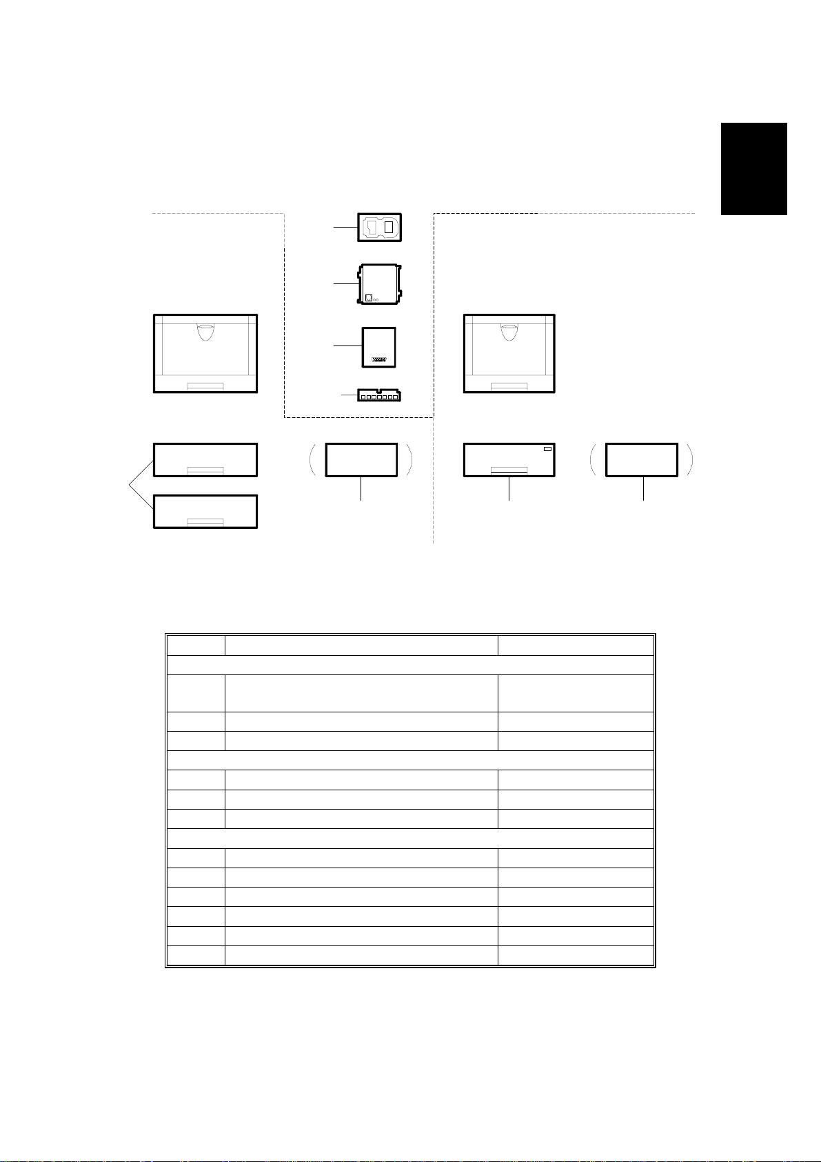
1.2 MACHINE CONFIGURATION
Internal Options
[G]
Stinger - P3
Stinger - P4
G031-17, 22, 27, 29 G032-17, 22, 27, 29
[E]
[F]
[H, I]
[A]
[B]
Overall
Information
[D][C]
G031V500.WMF
*NOTE:
No. Item Machine Code
Stinger - P3
A
B *Envelope Feeder Type 2000 G913-17
Stinger - P4
C Paper Feed Unit Type 1400 G914-57
D Envelope Feeder Type 1400 G913-57
Internal Option s
E Network Int erface Board Type 2000 G919-17
F RS232C Board Type 2000 G527-17
G Hard Disk Drive Type 2000 G690-17
H Memory Unit Type 204 (16 MB) G 688-04
Paper Feed Unit Type 2000 (A4/LT)
Paper Feed Unit Type 2000 (A3/DLT)
I Memory Unit Type 204 (32 MB) G688-05
G915-17, -27
G914-17, -27
The envelope feeder for the Stinger - P3 can only be installed in place of
the optional 2nd paper tray.
1-5
Page 16
PAPER PATH 12 March 1999
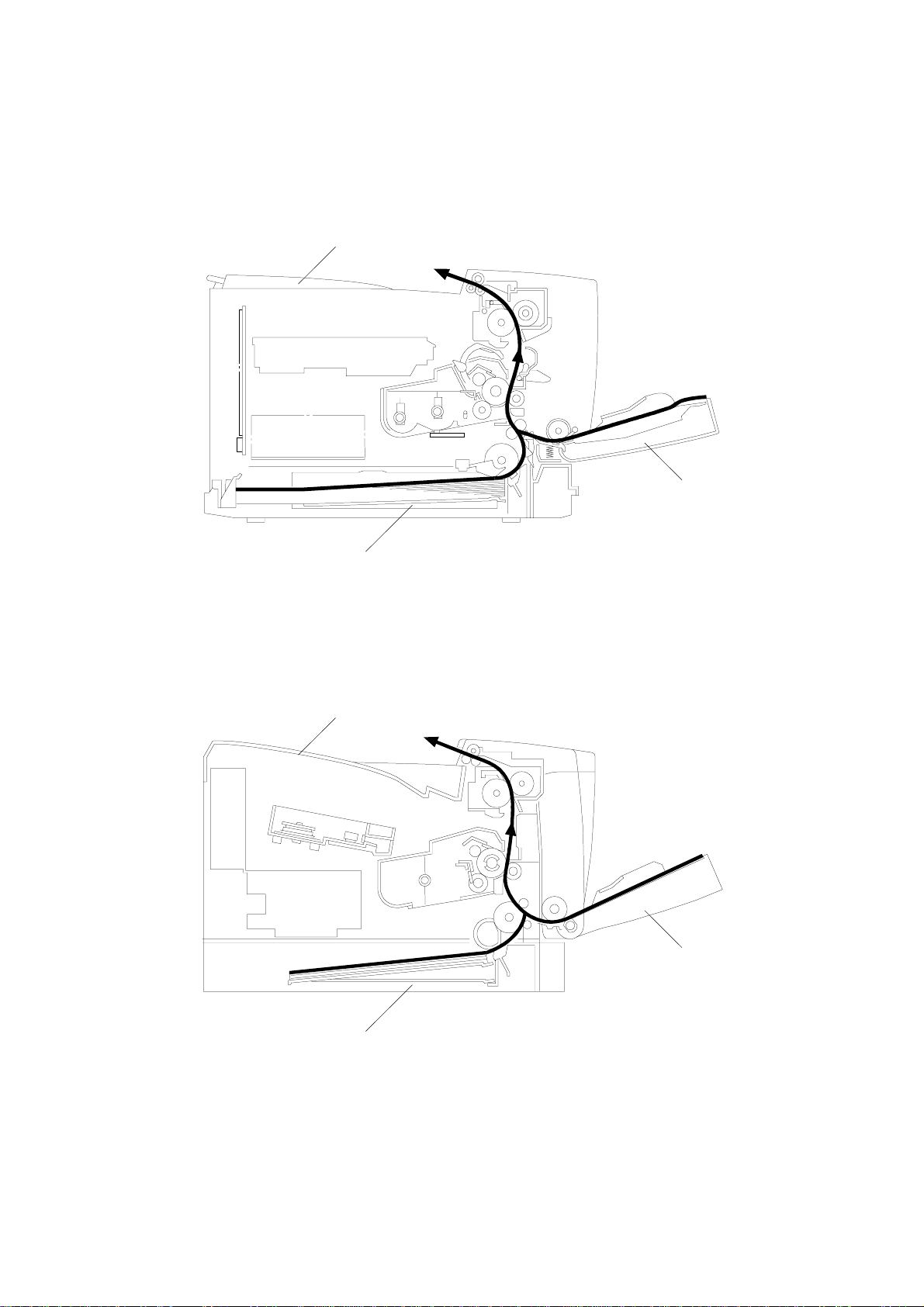
1.3 PAPER PATH
Stinger - P3
Output Tray
By-pass Tray
Stinger - P4
Paper Tray
Output Tray
G031V503.WMF
By-pass Tray
Paper Tray
G031V504.WMF
1-6
Page 17
12 March 1999 MECHANICAL COMPONENT LAYOUT
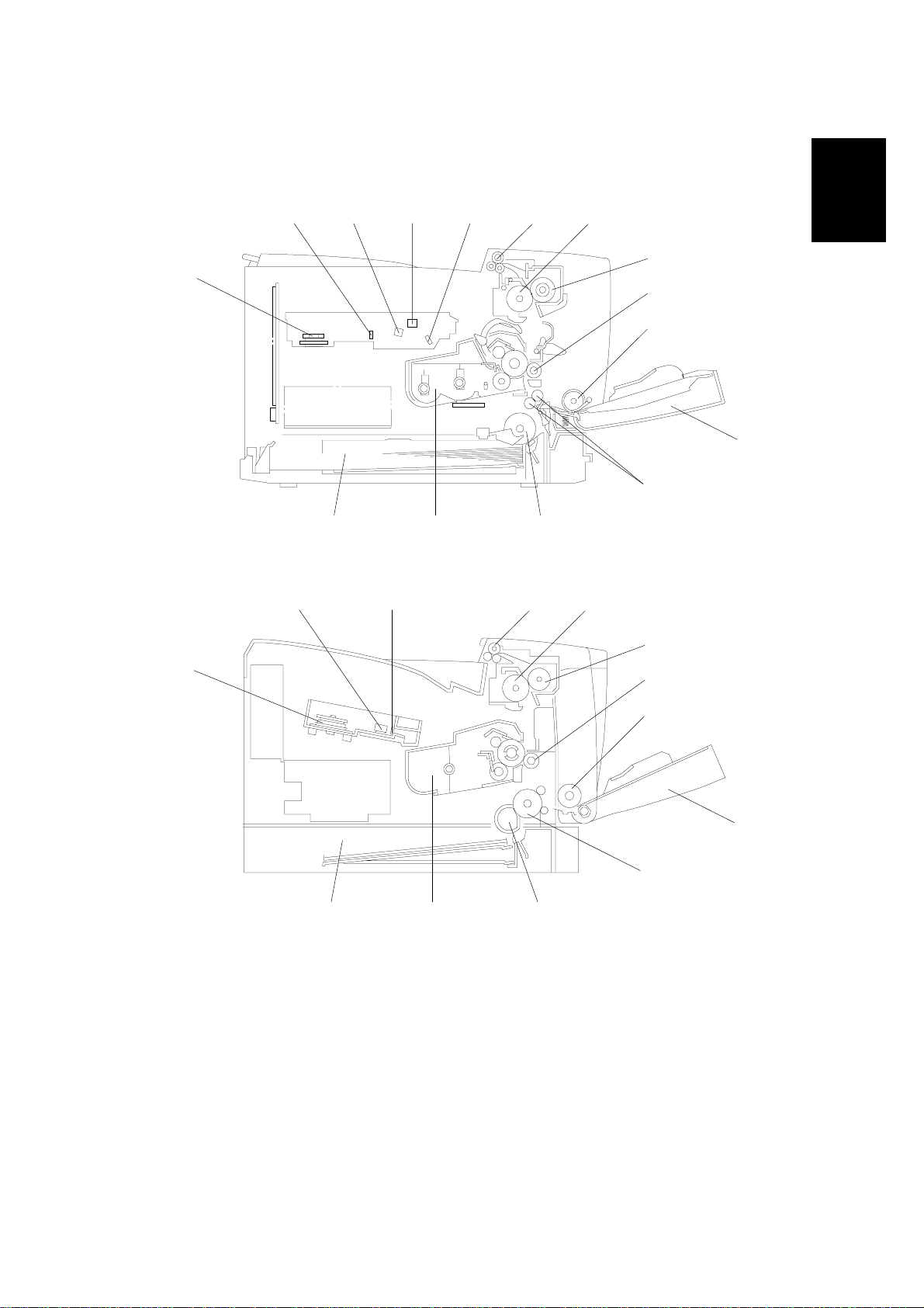
1.4 MECHANICAL COMPONENT LAYOUT
Stinger - P3
11
1312
14
15 1 2
3
4
5
6
7
Overall
Information
Stinger - P4
12
11
1. Exit Roller
2. Hot Roller
3. Pressure Roller
4. Transfer Roller
5. By-pass Feed Roller
6. By-pass Tray
7. Registration Rollers (Stinger - P3)
Relay Roller (Stinger - P4)
8. Paper Feed Roller
15 1 2
910 8
G031V505.WMF
3
4
5
7
910 8
G031V506.WMF
9. Toner Cartridge
10. Paper Tray
11. Polygonal Mirror Motor
12. 1st Mirror (Stinger - P3)
F-theta Lens (Stinger - P4)
13. Barrel Toroidal Lens (Stinger - P3)
14. F-theta Mirror (Stinger - P3)
15. Shield Glass
6
1-7
Page 18
ELECTRICAL COMPONENT LAYOUT 12 March 1999
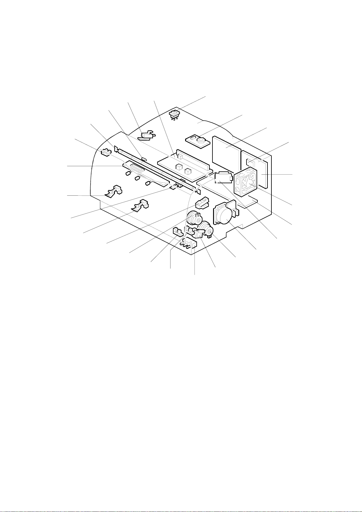
1.5 ELECTRICAL COMPONENT LAYOUT
Stinger - P3
17
16
15
18
14
19
20
13
12
21
11
22
10
23
24
25
1
2
3
4
5
6
7
8
9
G031V501.WMF
1. Laser Synchronization Detector
2. Engine Control Board
3. Exhaust Fan Motor
4. High Voltage Supply Board
5. LD Drive Board
6. Main Motor
7. Tray Paper Feed Clutch
8. By-pass Feed Solenoid
9. Tray Paper Size Switch
10. Registration Sensor
11. By-pass Tray Paper Sensor
12. Registration Clutch
13. Toner Near-end Sensor
14. Tray Paper End Sensor
15. Fusing Thermistor
16. Tray Paper Near-end Sensor
17. Control Panel Board
18. Fusing Exit Sensor
19. Fusing Lamp
20. Thermofuse
21. Front Cover Safety Switch
22. Power Supply Unit
23. Main Switch
24. Polygonal Mirror Motor
25. Printer Control Board
1-8
Page 19

12 March 1999 ELECTRICAL COMPONENT LAYOUT
Stinger - P4
18
19
20
Overall
Information
14
13
12
15
16
11
17
10
21
1
2
3
4
5
9
8
7
6
1. Engine Control Board
2. Exhaust Fan Motor
3. Power Supply Unit
4. High Voltage Supply Board
5. Main Motor
6. Tray Paper Feed Solenoid
7. By-pass Feed Solenoid
8. Toner Near-end Sensor
9. Registration Sensor
10. By-pass Tray Paper Sensor
11. Tray Paper End Sensor
G031V502.WMF
12. Fusing Exit Sensor
13. Fusing Thermistor
14. Control Panel Board
15. Fusing Lamp
16. Thermofuse
17. Front Cover Safety Switch
18. LD Drive Board
(with synchronization detector)
19. Main Switch
20. Polygonal Mirror Motor
21. Printer Control Board
1-9
Page 20
ELECTRICAL COMPONENT DESCRIPTIONS 12 March 1999
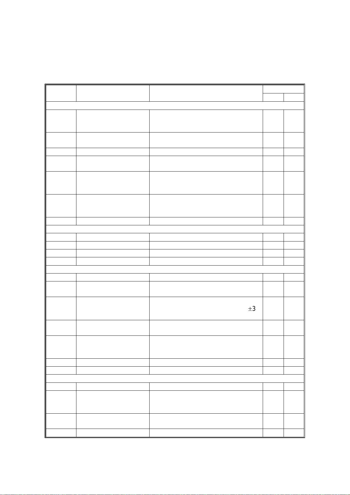
1.6 ELECTRICAL COMPONENT DESCRIPTIONS
Refer to the electrical component layout and the point-to-point diagram on the
waterproof paper in the pocket for the locations of these components.
Symbol Description Note
Printed Circuit Boards
High Voltage Supply
PCB1
PCB2
PCB3 LD Drive Board Controls the laser diode. 5 18
PCB4
PCB5
PCB6
Motors
M1 Main Drives the main body components. 6 5
M2 Polygonal Mirror Turns the polygonal mirror. 24 2 0
M3 Exhaust Fan Removes heat from the printer. 3 2
Board
Power Supply Unit
(PSU)
Control Panel Controls the display panel, LED, and
Engine Control Board
(ECB)
Printer Control Board
Supplies high voltage to the drum
charge roller, development roller, and
transfer roller.
Provides dc power to the system and
ac power to the fusing lamp.
the touch key pad.
Controls all base engine functions
either directly or through other control
boards.
Controls the PC interface, print image
processing, operation panel, and
other controller options.
Index No.
P3 P4
44
22 3
17 14
21
25 21
Sensors
S1 Fusing Exit Detects misfeeds. 18 12
S2
S3
S4
S5
S6 Toner Near-end Detects when toner is low. 13 8
Switches
SW1 Main Supplies power to the machine. 23 19
SW2
SW3
Tray Paper End Informs the CPU when the paper tray
runs out of paper.
Tray Paper Near-end
(Stinger - P3)
By-pass Tray Paper
Registration Detects the leading edge of the paper
Front Cover Safety Cuts the +5VLD and +24 V dc power
Tray Paper Size
(Stinger - P3)
Informs the CPU when the amount of
paper in the tray becomes low (50±30
sheets).
Informs the CPU when there is paper
on the by-pass tray.
to determine when to stop the paper
feed clutch, and detects misfeeds.
lines and detects whether the front
cover is open or not.
Determines the size of paper in the
paper tray, based on the dial setting.
14 11
16 —
11 10
10 9
21 17
9—
1-10
Page 21
12 March 1999 ELECTRICAL COMPONENT DESCRIPTIONS
Symbol Description Note
Index No.
P3 P4
Magnetic Clutches
MC1
MC2
Tray Paper Feed
(Stinger - P3)
Registration
(Stinger - P3)
Starts paper feed from the paper tray.
Drives the registration rollers.
7—
12 —
Solenoids
SOL1
SOL2
By-pass Feed Starts paper feed from the by-pass
tray.
Tray Paper Feed
Starts paper feed from the paper tray.
(Stinger - P4)
87
—6
Lamps
L1 Fusing Heats the hot roller. 19 15
Thermistors
TH1
Fusing Monitors the temperature of the hot
roller.
15 13
Thermofuses
TF1
Fusing
Provides back-up overheat protection
in the fusing unit.
20 16
Overall
Information
Others
LSD1
Laser Synchronization
Detector
(Stinger - P3)
Detects the laser beam at the start of
the main scan.
1—
1-11
Page 22
PRINTING PROCESS 12 March 1999
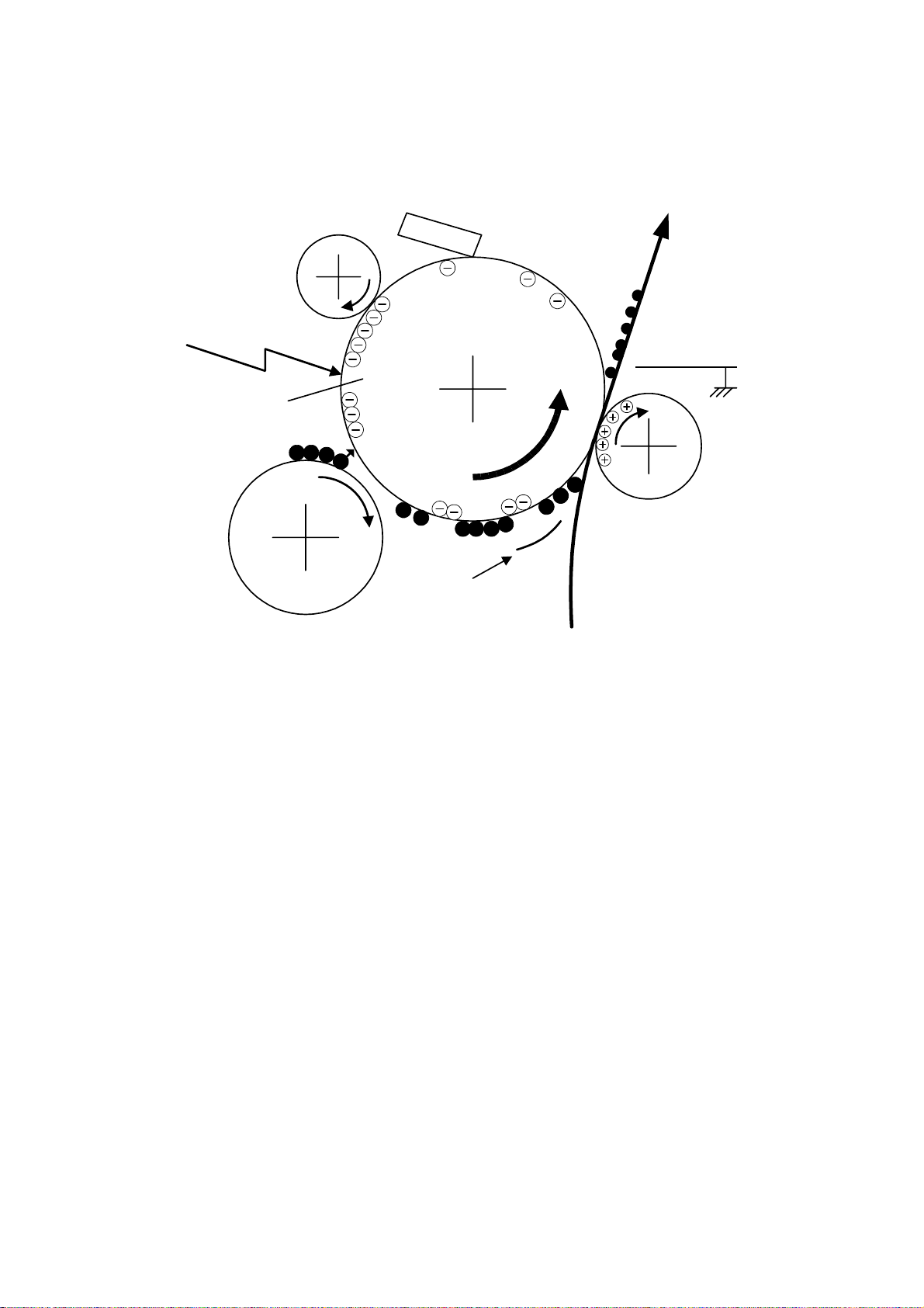
1.7 PRINTING PROCESS
6
1
OPC
–600 V
5
2
–100 V
4
3
–400 V
G031V507.WMF
Stinger - P3/4 use an all-in-one type of toner cartridge that includes the drum,
toner, development roller, charge roller and other components.
1. DRUM CHARGE
In the dark, the charge roller gives a negative charge of –600 volts to the organic
photo-conductive (OPC) drum. The charge remains on the surface of the drum
because the OPC layer has a high electrical resistance in the dark.
2. LASER EXPOSURE
The processed print image data from the engine control board (ECB) is transferred
to the drum by a laser beam, which forms an electrical latent image on the drum
surface. The areas exposed by the laser beam drop to about –100 volts.
3. DEVELOPMENT
The magnetic development brush on the development roller approaches the latent
image on the drum. The development roller gives a negative bias of –400 volts to
the toner. Toner particles jump and electrostatically attach to the areas of the drum
surface where the laser reduced the negative charge on the drum.
1-12
Page 23

12 March 1999 PRINTING PROCESS
4. IMAGE TRANSFER
Paper is fed to the area between the drum surface and the transfer roller at the
proper time for aligning the print paper and the developed image on the drum
surface. Then, the transfer roller applies a positive current to the reverse side of the
paper (the size of the current depends on the resolution and the paper size). This
pulls the toner particles from the drum surface to the paper. At the same time, the
paper is attracted to the transfer roller.
5. PAPER SEPARATION
Paper separates from the drum as a result of the electrostatic attraction between
the paper and the transfer roller. The discharge plate helps separate the paper
from the drum.
6. CLEANING
The cleaning blade removes any toner remaining on the drum surface after the
image is transferred to the paper.
7. QUENCHING
There is no quenching mechanism.
Overall
Information
1-13
Page 24
BOARD STRUCTURE 12 March 1999
g
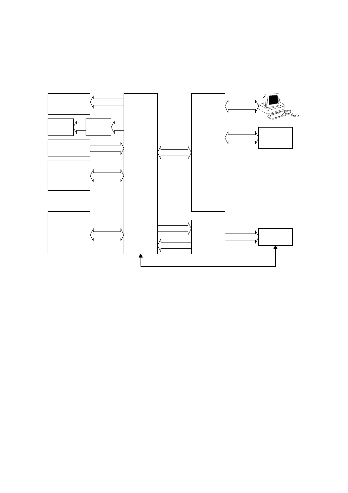
1.8 BOARD STRUCTURE
1.8.1 OVERVIEW
Motors &
Clutches
Laser
Diode
Sensors
High Voltage
Supply Board
Paper Feed
Unit
LD Drive
Board
Engine
Control
Board
(ECB)
Video I/F
+5 V/+24 V
Printer
Control
Board
Power
Supply
Unit
(PSU)
Control
Panel
Board
Fusin
Unit
G031V508.WMF
The engine control firmware controls the components connected to the engine
control board (ECB). The printer control board controls the control panel board.
The printer control board is also connected to the personal computer.
1-14
Page 25

12 March 1999 BOARD STRUCTURE
1.8.2 MAJOR COMPONENTS
1. Engine Control Board (ECB)
This is the printer engine control board. It controls the following functions:
·
Engine sequence
·
Machine control, printer engine control
·
Timing control for peripherals
·
Video control
·
Drive control for the sensors, motors, solenoids, and high voltage supply
board
·
PWM control for edge smoothing (PWM is done on the printer control board)
2. Printer Control Board
This is the machine’s main control board. It controls the following functions:
·
IEEE 1284 parallel port
·
Edge smoothing and toner saving
·
Engine control board
·
Control panel board
·
Interfacing with the HDD and NIB
3. LD Drive Board
Overall
Information
This is the laser diode drive circuit board.
4. Power Supply Unit (PSU)
Provides dc power to the system and ac power to the fusing lamp.
5. High Voltage Supply Board
Supplies high voltage to the drum charge roller, development roller, and transfer
roller.
6. Fusing Unit
Fuses toner to the paper. The fusing lamp is controlled by the ECB.
7. Control Panel Board
Controls the display panel, the LED, and the touch keypad.
1-15
Page 26
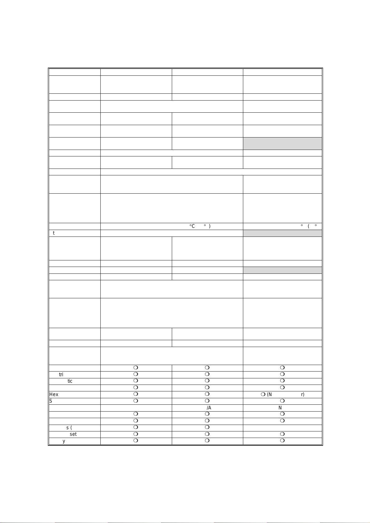
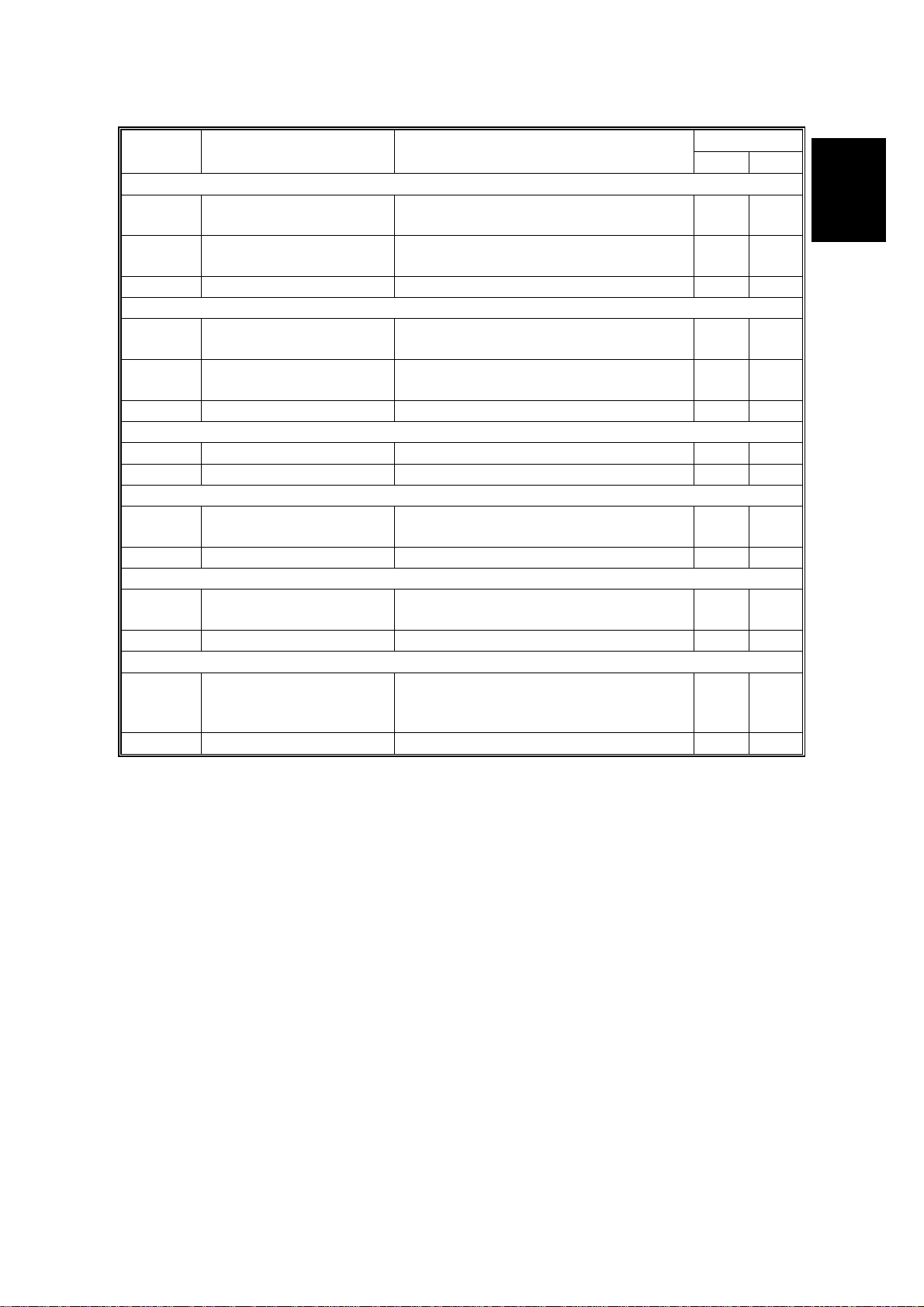
COMPARISON 12 March 1999
1.9 COMPARISON
Stinger - P3 Stinger - P4 V20
Standard Paper Tray
Standard Bypass Tray
Optional Paper Tray
Envelope Feeder 10 envelopes 5 envelopes 100 envelopes
Output Paper
Capacity
Input Paper Size
(Std./Opt. Tray)
Input Paper Size
(By-pass Tray)
First Print Speed
Duplex Printing N/A Option
Memory
(Std./Max. with Opt.)
HDD (Option) 1.6 GB
Fonts
Interface Bi-directional parallel x 1
Warm-up Time
Utilities Aficio Manager
Dimensions
(mm: W x D x H)
Weight Less than 15 kg (33 lb.) Less than 12 kg (27 lb.) Less than 44.5 kg (99 lb.)
Consumable Yield Toner Cartridge: 14 K Toner Cartridge: 8 K
PM Kit Maintenance Kit: 80 K Maintenance Kit: 60 K
Technology
Resolution True 1,200 x 1,200 dpi (PCL6/PS)
Continuous Print
Speed
Power Consumption Max. 795 W Max. 600 W Max. 950 W
Drivers PCL6/5e version : Windows 3.1x, 95(98), Windows NT 4.0
Halftoning
Electrical Sorting
Diagnostic Test Mode
Test Print
Hex Dump List
Smoothing
Rotated Sorting N/A N/A N/A
Toner Saving Mode
PDL Auto Change
Overlays (PCL)
Auto Cassette Change
Energy Saver
250 sheets
100 sheets
500 sheets x 2
250 sheets
A3/11" x 17" ~ A5 (LEF) A4 ~ A5 (LEF) A3/11" x 17" ~ A5/5.5" x 8.5" (LEF)
A3/11" x 17" ~ B6 (SEF) free:
11.69" x 17" ~ 3.88" x 5.83"
5.5 s or less
(A4/LT ~ LEF, Standard Tray)
8 MB/40 MB 8 MB/ 40 MB 8 MB/68 MB
PCL6 (35 Intellifonts, 10 True Type fonts and 1 bitmap font)
PS2 (35 Adobe type 1 fonts)
Ethernet (100 Base-Tx/10 Base-T for TCP/IP, IPX/SPX, Ether
Talk)
RS232C (Optional)
Less than 39 seconds: 23°C (73°F) Less than 60 seconds: 23°C (73°F)
450 x 420 x 270 mm
(with Std. Tray adjusted for A4)
450 x 555 x 270 mm
(with Std. Tray adjusted for A3)
Laser beam scanning & electrophotographic printing
Monocomponent development
600 x 600 dpi (PCL6/PCL5e/PS)
300 x 300 dpi (PCL5e/PS)
20 ppm (A4 SEF) 14 ppm (A4 LEF) 25 ppm (A4/LT LEF)
PS PPD: Windows 95 (98), Windows NT 4.0, Macintosh OS 7.5
or later
mm m
mm m
mm m
mm m
mm
mm m
mm m
mm m
mm
mm m
mm m
A4/LG ~ B6 (SEF) free:
8.5" x 14" ~ 3.88" x 5.83"
(A4/LT ~ SEF, Standard Tray)
360 x 420 x 270 mm
(with Std. Tray adjusted for A4)
250 sheets
100 sheets
500 sheets
6.5 s or less
500 sheets x 2 + 1,500 sheets
Standard Output Tray: 400 sheets
A3/11"x17" ~ A5/5.5" x 8.5" (SEF)
PCL5e (35 Intellifont, 10 True Type
font and 1 bitmap font)
PS2 (35 Adobe type 1 fonts)
Bi-directional parallel (Standard)
Ethernet (10 Base 2/T for
IPX/SPX, TCP/IP, Apple Talk)
Token Ring (4 Mbps, 16 Mbps for
IPS/SPX, TCP/IP, Apple Talk)
530 x 625 x 472 mm
(with by-pass tray closed, without
the optional paper tray unit, without
options)
Laser beam scanning &
electrophotographic printing
Dualcomponent development
600 dpi, 400 dpi (available when
the PostScript option is installed),
300 dpi (simulated by doubling
pixel width and height at 600 dpi
resolution)
PCL version : Windows 3.1xx, 95,
Windows NT 3.51/4.0 (PCL & PS
version: Macintosh)
250 sheets
100 sheets
External Tray: 100 sheets
m
(N/A from Driver)
N/A
1-16
Page 27
12 March 1999 PRINTING
2. DETAILED SECTION DESCRIPTIONS
2.1 PRINTING
2.1.1 IMAGE DATA PATH
Drum
LD Unit
LD Drive
Board
ECB
PC AT
Compatible
Parallel
Gate
Array
Printer Control Board
Macintosh
Ethernet
NIB
Optional Bus I/F
CN.
ROCKY W
G031D502.WMF
The printer control board receives the print data from the host computer (AT
compatible Windows PC or Macintosh).
·
For the Stinger - P3, the printer control board has two OBI (Optional Bus
Interface) connectors to connect a network interface board (NIB), RS232C
interface, or HDD unit.
·
For the Stinger - P4, the printer control board has one OBI connector.
Detailed
Descriptions
The printer control board generates the print image data and sends it with
commands to the ECB (Engine Control Board).
The printer control board contains the image processing ASIC (ROCKY W). The
ROCKY W ASIC controls the image processing, IEEE1284 interface, DRAM, edge
smoothing, and toner saving. (ASIC: Application Specific Integrated Circuit)
The ECB contains a gate array. The gate array controls LD print timing control and
the serial interface to the printer control board.
Finally, the ECB sends the video data to the LD drive board.
2-1
Page 28
PRINTING 12 March 1999
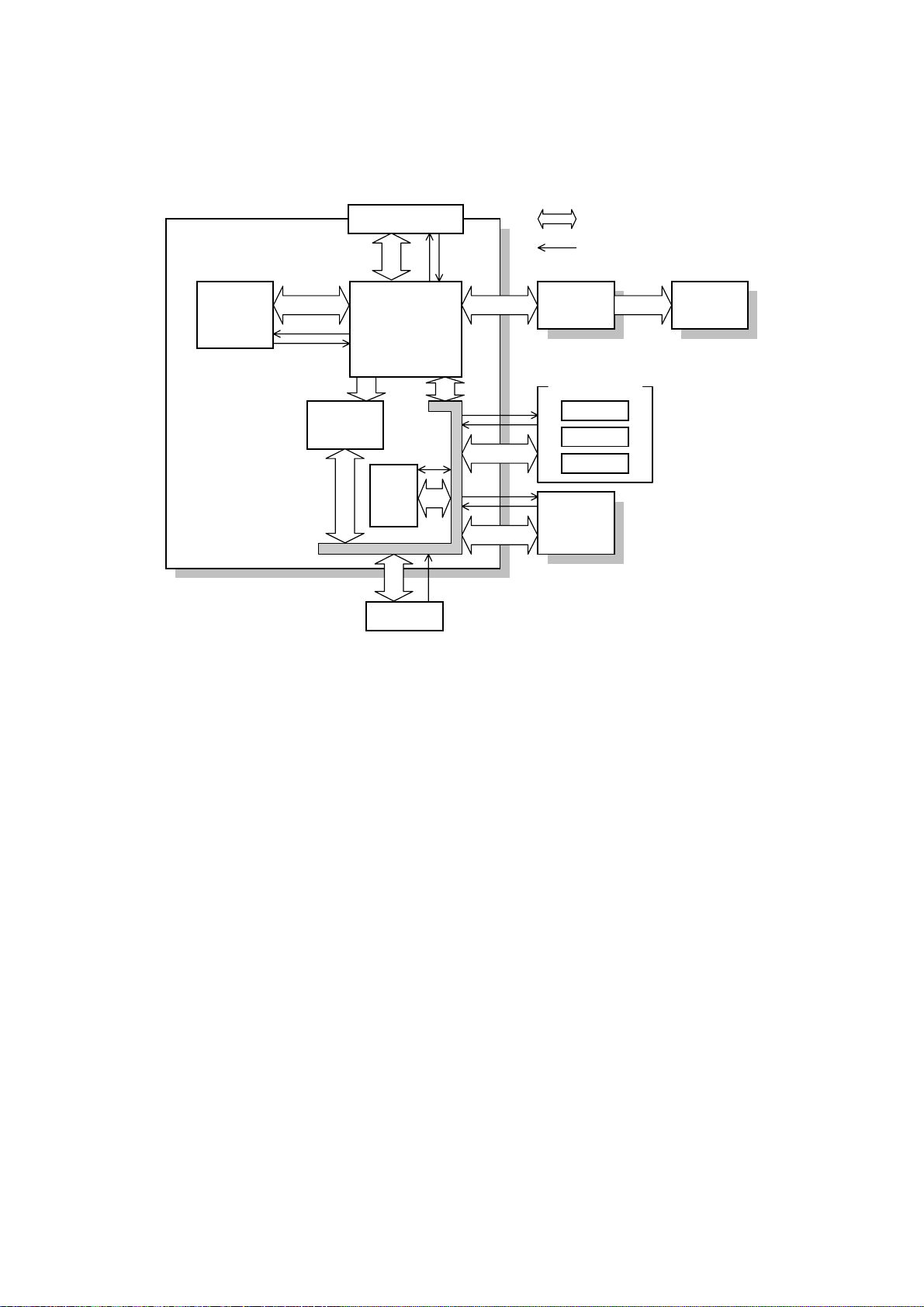
2.1.2 PRINTER CONTROL BOARD
CPU
Printer
Control Board
Parallel I/F
ROCKY W
Resident
DRAM
32-bit Data
Address/Command
ECB LD Unit
(ASIC)
Option Board
NIB
HDD
RS232C
Code
ROM
DIMM
SIMM
G031D503.WMF
The printer control board receives the print data from the computer through the
parallel cable or network interface board.
The printer control board contains the CPU (which is a 64-bit RISC processor), the
ROCKY W ASIC, 8 MB of resident DRAM for main memory, and a 8 MB code
ROM.
A SIMM card can be installed for extra DRAM memory and a DIMM card can be
connected for service purposes (firmware upgrade).
The control board controls the following to produce the print image data.
1) IEEE1284 parallel port interface
2) Control panel
3) Edge smoothing and toner saving
4) Engine control board
5) Interfacing with the HDD, NIB, and RS232C board.
2-2
Page 29
12 March 1999 PRINTING
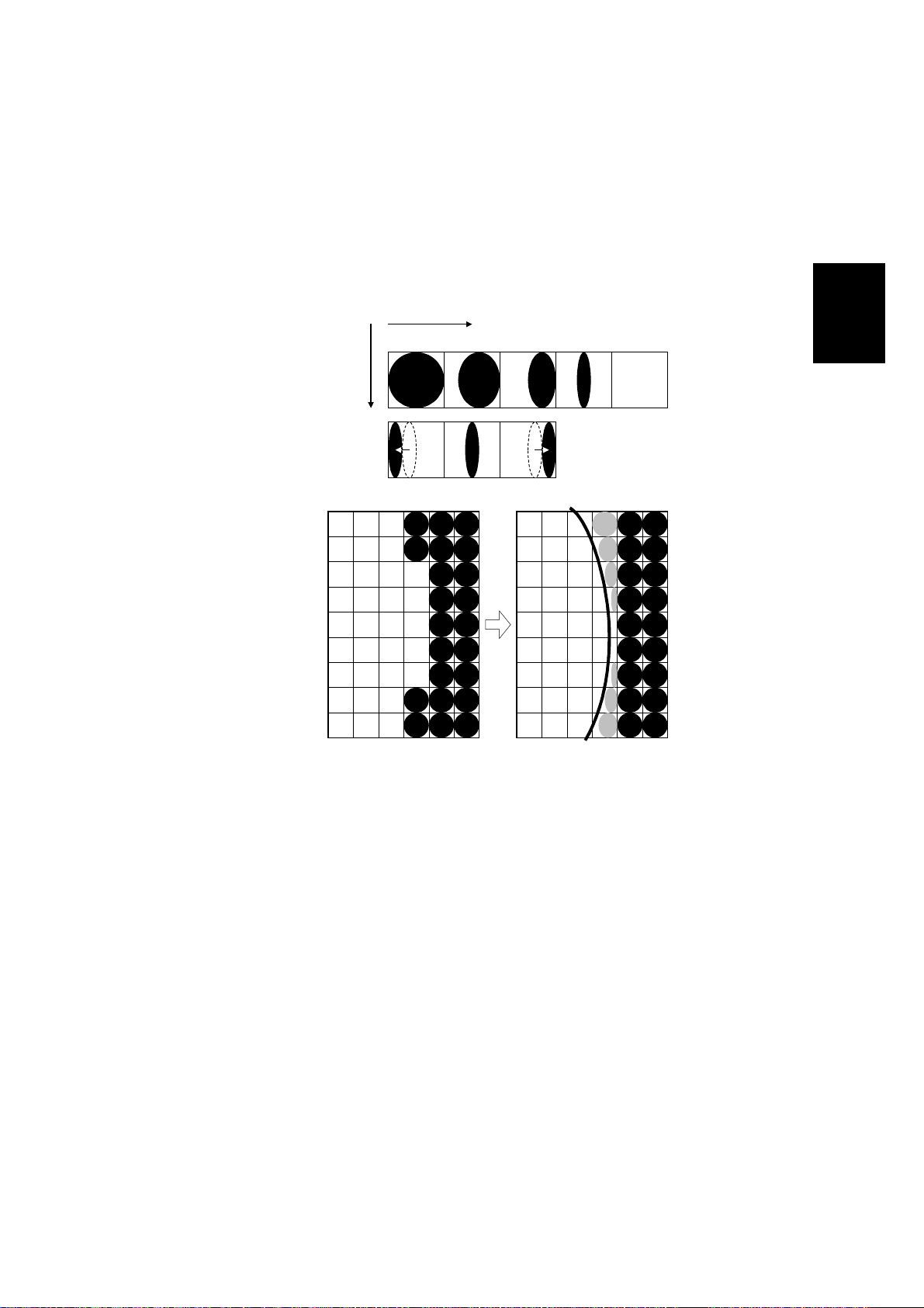
2.1.3 IMAGE DATA PROCESSIING
Edge smoothing and toner saving are performed by an ASIC (ROCKY W). The
edge smoothing and toner saving modes can be switched on/off with the machine’s
control panel or the printer driver.
Edge Smoothing
Fig. A
Fig. B
Fig. C
Sub Scan
Direction
Main Scan Direction
4/4 3/4 2/4 1/4 0
G031D504.WMF
Detailed
Descriptions
Jagged edges on characters as shown in the above illustration are reduced using
edge smoothing. Edge smoothing changes the laser pulse duration and position for
certain pixels.
Fig. A shows the four possible pulse durations, and Fig. B shows how the laser
pulse can be in one of three positions within the pixel. Fig. C shows an example of
how edge smoothing is used.
Edge smoothing is not done for 1,200-dpi printing.
Toner Saving Mode
Toner saving is done by reducing the number of black dots in the printed image. An
8 x 8 matrix filter is used.
As a result, less toner is used to create the latent image on the drum and black
areas print as gray.
The printer driver prevents edge smoothing and toner saving mode from being
used at the same time.
2-3
Page 30

PRINTING 12 March 1999
2.1.4 HOST INTERFACE
Bi-directional Parallel Interface
G031D505.WMF
A 36-pin bi-directional parallel interface connector (female) is used.
The bi-directional parallel interface on the controller works in three modes;
Compatible, Nibble and ECP modes. These modes are standardized by IEEE
1284.
2-4
Page 31

12 March 1999 LASER EXPOSURE
2.2 LASER EXPOSURE
2.2.1 OVERVIEW
This machine uses a laser diode to produce electrostatic images on an OPC drum.
The laser diode unit converts image data from the ECB into laser pulses, and the
optical components direct these pulses to the drum.
Exposure of the drum by the laser beam creates the latent image. The laser beam
makes the main scan while drum rotation controls the sub scan.
Stinger - P3 Stinger - P4
Strength of the beam output 5 mW 5 mW
Strength of the beam on the drum 0.636 mW 0.43 mW
Printing Binary (2 bits/pixel) Binary (2 bits/pixel)
There are two polygon motor speeds:
Detailed
Descriptions
-
Stinger - P3
Resolution (dpi) Modes Motor Speed (rpm) Data Frequency (MHz)
600 300/600 dpi printing 22478.22 22.0926
1,200 1,200 dpi printing 22478.22 44.1851
-
- Stinger - P4 -
Resolution (dpi) Modes Motor Speed (rpm) Data Frequency (MHz)
600 300/600 dpi printing 22377.62 15.0528
1,200 1,200 dpi printing 22377.62 30.1056
Differences between 1,200 dpi and 600 dpi printing
To produce 1,200 dpi, the machine uses a di ffere nt data frequency for the main
scan and a different line speed for the sub scan, compared with 600 dpi printing.
For 1,200 dpi printing, the polygon motor works at the same speed as for 600 dpi
printing but the data frequency is twice as fast as in 600 dpi printing.
The paper at 1,200 dpi is fed at half the speed used for 600 dpi, as follows.
600 dpi printing 1,200 dpi printing
Paper feed line speed 92 mm/s 46 mm/s
The beam diameter for 1,200 dpi printing is the same as for 600 dpi printing.
2-5
Page 32

LASER EXPOSURE 12 March 1999
2.2.2 OPTICAL PATH
Stinger - P3
Stinger - P4
[H]
[G]
[A]
[F]
[A]
[J]
[B]
[E]
[C]
[K]
[D]
G031D506.WMF
[C]
[A]: Polygonal Mirror
[B]: Cylindrical Lenses
[C]: LD Drive Board
[D]: Drum
[E]: LD Shutter
[F]: F-Theta Mirror
[I]
[B]
[E]
[D]
G031D507.WMF
[G]: BTL (Barrel Toroidal Lens)
[H]: 1st Mirror
[I]: F-theta Lens
[J]: Laser Synchronization Detector
[K]: Shield Glass
[J]
[K]
2-6
Page 33

12 March 1999 LASER EXPOSURE
The optical path from the laser diode to the drum is shown on the previous page.
The LD drive board [C] outputs the laser beam to the polygonal mirror [A] through
the cylindrical lenses [B], which focus the laser beam.
Stinger - P3
The laser beam goes to the F-theta mirror [F], 1st mirror [H] and BTL [G]. Then, the
beam reaches the drum [D] through the shield glass [K].
The beam reflected by the polygonal mirror writes the pixels of the latent image on
the drum. The F-theta mirror [F] ensures constant intervals between the pixels. The
BTL [G] corrects for irregularities in the polygonal mirror faces.
The laser synchronization detector [J] synchronizes the start of the main scan.
Stinger - P4
The Stinger - P4 has a shorter beam path than the Stinger - P3.
The beam which is reflected by the polygonal mirror goes to the F-theta lens [I].
The beam reaches the drum [D] through the shield glass [K]. The F-theta lens [I]
does the functions of both the F-theta [F] mirror and the BTL [G].
The LD drive board for the Stinger - P4 contains the laser synchronization detector.
Detailed
Descriptions
2-7
Page 34

LASER EXPOSURE 12 March 1999
2.2.3 AUTO POWER CONTROL (APC)
LD Drive Board
5V
APC
VIDEO
DPI select
LD OFF
CN1-7
VCC
LD Driver
LD
PD
G031D508.WMF
To prevent the intensity of the laser beam from changing because of temperature,
the machine monitors the laser beam with a photodiode (PD). The PD is enclosed
in the laser diode. The PD passes an electrical current to the LD driver IC and this
IC adjusts its output level to keep the laser diode output constant.
The laser diode power level is adjusted on the production line. Do not touch the
variable resistors on the LD unit in the field.
2-8
Page 35

12 March 1999 LASER EXPOSURE
g
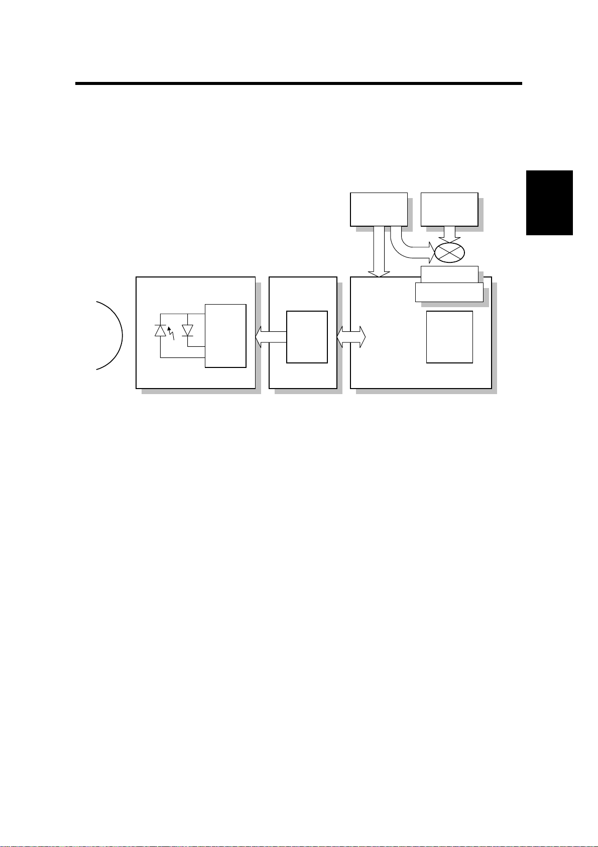
2.2.4 LD SAFETY SWITCH
Power Supply
Unit
CN104-1
+24V
CN103-2CN103-1
Front Cover
Safety Switch
Engine Control
Board
Voltage
ulator
Re
LD Drive Board
CN7-7 CN1-7CN16-1
LD Driver
LD
PD
G031D500.WMF
Front Cover Safety Switch
To ensure that the laser beam does not inadvertently switch on during servicing,
there is a safety switch located at the front cover. The switch is on the LD 24 V line.
Detailed
Descriptions
Mechanical Laser Shutter
When the toner cartridge is removed, the laser shutter is released and this
interrupts the laser beam.
2-9
Page 36

TONER CARTRIDGE 12 March 1999
2.3 TONER CARTRIDGE
2.3.1 OVERVIEW
[A]
[B]
[C]
[D]
[E]
[H][I]
[G] [F]
G031D509.WMF
The toner cartridge consists of the components shown above. The toner cartridge
contains the OPC drum and the toner cassette, and includes the mechanisms for
drum charge, development, and cleaning. The drum is 30 mm in diameter.
[A]: Charge Roller
[B]: Cleaning Blade
[C]: OPC Drum
[D]: Transfer Roller
[E]: Transfer Blade
The main motor drives the rollers in the toner cartridge. The charge roller [A]
charges the drum [C]. Monocomponent toner is used. The cleaning blade [B]
cleans the drum surface.
[F]: Development Roller
[G]: Mixing Blade
[H]: Toner Near-end Sensor
[I]: Agitator
2-10
Page 37

12 March 1999 TONER CARTRIDGE
2.3.2 DRIVE
[A]
[B]
[D]
[C]
G031D510.WMF
The main motor [B] drives the drum [C], the development roller [A], and agitators
[D] through a series of gears. The main motor speed is controlled by the engine
control board (ECB).
Detailed
Descriptions
When a new ca rtridge is installed, the machine clears the near-end condit i on if the
toner near-end sensor detects that there is sufficient toner.
There is no counter for the toner cartridge.
2-11
Page 38

TONER CARTRIDGE 12 March 1999
2.3.3 DRUM CHARGE
[A]
[B]
[E]
[C]
[D]
G031D511.WMF
This machine uses a drum charge roller system instead of a scorotron corona wire
system to charge the drum. The drum charge roller [A] always contacts the surface
of the drum [E] because of the charge roller pressure springs [C], and gives a
negative charge to the drum surface. While the drum is rotating, the drum charge
roller also turns because of friction between the roller and the drum.
The drum charge roller system generates less ozone than a scorotron corona wire
charge system. Due to this, there is no ozone filter in the machine.
The high voltage supply board applies voltage to the drum charge roller through
the charge roller terminal [B], charge roller pressure spring [C], and the charge
roller bushing [D]. Both ac and dc are applied.
Before the laser starts to write to the drum, the charge roller receives –600Vdc and
2 kV peak-to-peak 1 kHz ac from the high voltage supply board. This gives the
drum surface a uniform negative charge of -600 V.
The dc and ac are continually supplied during the printing job. This gives the drum
surface a uniform –600 V charge wherever it passes the charge roller.
At the end of the job, the dc is set to 0 V, but the ac stays on. While the drum
rotates past the charge roller, the ac brings the charge on the drum surface to a
uniform 0 V.
The toner cartridge has no cleaning pad, temperature control, or contact
mechanism for the drum charge roller (the material of the drum charge roller allows
a simple mechanism). The drum charge roller is part of the toner cartridge, so
when the toner runs out, the drum charge roller is changed at the same time. This
happens before the drum charge roller gets dirty.
2-12
Page 39

12 March 1999 TONER CARTRIDGE
2.3.4 DEVELOPMENT
Overview
[F]
[A]
[G]
[B]
[E]
[D] [C]
G031D509.WMF
This machine uses monocompo nent to ner . The Sting er - P3 has two agitators [F] in
the toner cartridge(shown above). The Stinger - P4 has one agitator.
Detailed
Descriptions
The agitator(s) [F] and the mixing blade [D] mix the toner in the toner cartridge and
transport it to the development roller [C]. Friction between the transported toner
and the doctor blade [A] gives the toner a negative charge.
Internal permanent magnets in the development roller attract the toner to the
development roller sleeve. The doctor blade trims the toner to the desired
thickness on the development roller sleeve. The development roller does not
contact the drum [G]. There is a small gap between the toner on the surface of the
development roller sleeve and the drum. Toner jumps across this gap to develop
the latent image.
The development bias consists of ac and dc components. The ac component
improves the transfer of toner.
The transfer blade [B] is charged to the same voltage as the development bias.
This helps to keep the toner on the drum.
The toner near-end sensor [E] is located under the toner cartridge.
2-13
Page 40

TONER CARTRIDGE 12 March 1999
Toner Near-End Sensor
The toner near-end sensor monitors the toner concentration by checking the
magnetic field strength.
When the reading goes down to a threshold value, the machine enters the nearend condition. There is no toner end condition (the user replaces the cartridge
when the print quality has become unacceptable). The threshold value cannot be
changed.
No adjustment is required after the sensor is replaced.
Toner Supply
The toner in the toner cartridge is mixed by the agitator(s) and mixing blade. The
toner near-end sensor is not used to control toner supply. When the machine is
turned on or the front cover is closed, the agitator(s) and the mixing blade rotate to
mix the toner for a brief period.
Development Bias
The high voltage supply unit gives the development roller a charge of –400 V dc
and an ac component of 1.8 kVp-p 1.8 kHz ac is also used. To prevent toner from
transferring to non-image areas on the drum, the development bias is different for
image areas and non-image areas.
2-14
Page 41

12 March 1999 TONER CARTRIDGE
2.3.5 DRUM CLEANING
[D]
[A]
[B]
[C]
Detailed
Descriptions
G031D512.WMF
The cleaning blade [A] removes any toner remaining on the drum after the image is
transferred to the paper. The toner remaining on the drum is scraped off by the
cleaning blade and transferred to the collection area. The mylar sheet [B] prevents
the toner from dropping out of the cleaning unit.
The toner cartridge in the commercial toner cartridge has a toner collection coil [C]
and scraper [D]. These improve the collection of waste toner.
There is no toner recycling mechanism.
2-15
Page 42

IMAGE TRANSFER AND PAPER SEPARATION 12 March 1999
2.4 IMAGE TRANSFER AND PAPER SEPARATION
2.4.1 OVERVIEW
[C]
[A]
[B]
G031D513.WMF
The machine uses a transfer roller [A] which touches the surface of the drum [B].
The high voltage supply unit supplies a positive current to the transfer roller. A
feedback circuit inside the machine automatically keeps the transfer current
constant.
The current depends on the paper size. For A3 paper in the Stinger - P3, 7mA is
supplied, and for A4 paper in the Stinger - P4, 6mA is supplied (for 600 dpi
resolution in both of these cases).
The transfer roller attracts the toner from the drum onto the paper.
Drive from the drum through a gear drives the transfer roller.
The discharge plate [C] and the curvature of the drum helps the paper to separate
from the drum. The discharge plate is connected to ground.
2-16
Page 43

12 March 1999 IMAGE TRANSFER AND PAPER SEPARATION
2.4.2 TRANSFER ROLLER CLEANING
If the paper size is smaller than the printed image, or if a paper jam occurs during
printing, toner may be transfered to the roller surface. To prevent this toner from
transferring to the back side of the printouts, the transfer roller has to be cleaned
before the next printing run.
During transfer roller cleaning, the high voltage supply unit supplies a negative
cleaning bias to the transfer roller. The negatively charged toner on the transfer
roller is then transferred back to the drum. Then a positive cleaning bias is applied
to the transfer roller to push back to the drum any toner which was positively
charged by the transfer roller.
The machine goes through the cleaning mode in the following conditions:
·
After a printer jam has been cleared.
·
Just after the power is switched on.
·
After 10 sheets of paper have been printed and the print job has finished.
Detailed
Descriptions
2-17
Page 44

PAPER FEED 12 March 1999
2.5 PAPER FEED
2.5.1 OVERVIEW
Stinger - P3
[C]
[D]
[B]
[A] [E]
There is a paper tray [A] and a by-pass tray [B].
The paper tray holds 250 sheets. The by-pass tray can hold 100 sheets of paper.
The paper feed roller [C] drives the top sheet of paper from the paper tray to the
registration rollers [D].
The paper tray has a friction pad [E] which allows only one sheet to feed at a time.
When the paper tray is closed af ter the paper is loaded, the paper size actuator
(behind the paper size indicator, which is located at the front right of the tray)
pushes the tray paper size switch. This informs the CPU what paper size is loaded
in the tray and that the tray is in place.
The tray can be extended manually to hold paper longer than A4/Letter size.
G031D514.WMF
2-18
Page 45

12 March 1999 PAPER FEED
Stinger - P4
[B]
Detailed
Descriptions
[D]
[C]
[A] [E]
G031D515.WMF
There is a paper tray [A] and a by-pass tray [B].
The paper tray holds 250 sheets. The by-pass tray can hold 100 sheets of paper.
The paper feed roller [C] drives the top sheet of paper from the paper tray to the
relay roller [D]. Then the relay roller feeds the paper to the registration area.
The paper tray has a friction pad [E] which allows only one sheet to feed at a time.
This machine does not have a paper size switch. So, before printing, the user must
register the paper size in the paper tray at the printer’s operation panel.
The built-in tray can only hold A4 or letter size paper.
2-19
Page 46

PAPER FEED 12 March 1999
2.5.2 PAPER TRAY
Stinger - P3
Tray Extension
The tray can be extended manuall y
to hold paper longer than A4/Letter
size. The default setting of the tray
length is for short paper. To use
longer paper, release the catches
[A] at both sides, then extend the
tray and re-lock the catches.
The paper sizes in the table given
below can be used.
Tray mode Possible Paper Sizes
Short
(default)
Long
A5 Landscape, B5 Landscape, A4 Landscape, 7
8
" x 11" Landscape, 8
1/2
" x 13" Portrait, 8" x 13" Portrait, 8
8
1/2
Portrait, B4 Portrait, A3 Portra it, 11" x 17" Portr ait
[A]
" x 11" Portrait, A4 Portrait
1/2
" x 13" Portrait, 8
1/4
1/4
" x 10
G031D516.WMF
" Landscape,
1/2
" x 14"
1/2
Bottom Plate Lift
The tray bottom plate [B] is connected
to the cassette arms [C] by springs
[D]. When the cassette is put in the
machine, the slopes of the guide
blocks [E] on the machine lift the
cassette arms up and the springs
keep the stack of paper at the correct
height. When the paper is used up,
the springs pull the tray bottom plate
up as shown in the picture.
[E]
[D]
[B]
[C]
G031D517.WMF
2-20
Page 47

12 March 1999 PAPER FEED
Paper Feed Drive
[E]
[F]
[A]
[B]
[C]
[D]
Detailed
Descriptions
G031D518.WMF
The main motor drives the pick-up an d fe ed mec hanism. The tray paper feed clutc h
[A] transfers drive from the main motor to the paper feed roller [B].
This machine uses a feed roller and friction pad mechanism. The friction pad [C]
only allows the top sheet to feed. Therefore, during paper feed, the top sheet of
paper is separated from the stack and fed to the registration rollers [D].
When the paper actuates the registration sensor [E], the tr ay paper feed clutch
turns off. When the paper reaches a certain position, the registration clutch [F]
turns on to transfer drive from the main motor to the registration rollers. Then the
registration rollers feed the paper to the transfer area.
2-21
Page 48

PAPER FEED 12 March 1999
Paper Size Detection
The paper size switch [A] includes
three sensors (microswitches). The
sensors are actuated by actuators on
[C]
[D]
[A]
a dial [B] behind the paper size
indicator plate.
Each paper size has its own actuator,
with a unique combination of notches.
To determine the paper size, the CPU
reads which switches have been
turned off by the actuator.
[B]
The CPU disables paper feed from a
tray if the paper size cannot be
G031D519.WMF
detected. If the paper size actuator is
broken, or if there is no tray installed, the printer control board recognizes that the
paper tray is not installed.
When the paper size actuator is at the "]" mark, the paper tray can be set up to
accommodate one of a wider range of paper sizes by using a user tool at the
machine’s operation panel.
Models Switch Location
North America Europe Left Center Right
8
" x 14" Portrait A5 Landscape On On On
1/2
A4 Landscape A4 Landscape On Off Off
8
" x 11" Portrait A4 Portrait On On Off
1/2
]]
8
" x 13" Portrait 8
1/2
8
" x 11" Landscape 8
1/2
11" x 17" Portrait A3 Portrait Off Off On
" x 13" Portrait Off On Off
1/2
" x 11" Landscape On Off On
1/2
Off On On
On: Pushed Off: Not Pushed
Paper End Detection
When the paper tray runs out of paper, the feeler of the tray paper end sensor
drops into the cutout in the tray bottom plate and this activates the paper end
sensor [C].
Paper Near End Detection
When almost 50 sheets are left on the tray, th e tray bottom pla te pushes up the
feeler of the tray paper near end sensor [D]. However, there is no indication on the
printer’s operation panel; the signal is only for use by the host computer.
2-22
Page 49

12 March 1999 PAPER FEED
Stinger - P4
Bottom Plate Lift
[C]
[A]
[B]
Detailed
Descriptions
G031D520.WMF
The tray bottom plate is connected to the cassette arm [A] by the spring [B]. When
the cassette is put in the machine, the slope of the guide block [C] on the machine
lifts the cassette arm up and the spring lifts up the bottom plate.
2-23
Page 50

PAPER FEED 12 March 1999
Paper Feed Drive
[B]
[D]
[E]
[F]
[C]
[G]
[A]
[I]
[H]
G031D521.WMF
The main motor drives the pick-up and feed mechanism through the paper pick-up
drive gear [D].
To pick up paper, the tray paper feed solenoid [A] turns on and the gear stopper [B]
comes off the paper feed roller gear [C]. This gear does not move immediately,
because the gap in the teeth prevent it from engaging the drive gear [D]. It is first
turned clockwise by a spring until its teeth engage with the drive gear, which now
drives the paper feed roller [E].
At the same time, the cam behind the paper feed roller gear moves the stopper
release lever [G], and this releases the bottom plate stopper [H]. The bottom plate
can then lift the top of the paper stack to the correct height for paper feed.
This machine uses a feed roller and friction pad mechanism. The friction pad [F]
only allows the top sheet to feed to the relay roller [I].
After one turn, the paper feed roller gear stops because the part of the gear without
teeth is now back at the starting position, opposite the pick-up drive gear. The gear
stopper and bottom plate stopper also return to their previous positions
Then the relay rollers feed the paper to the transfer area.
NOTE:
If the gear stopper comes off the paper feed roller gear as a result of shock
or vibration and paper is placed in the tray, the machine starts to feed
paper as soon as it is turned on. To fix this problem, remove all paper from
the paper tray then turn on the machine.
Paper End Detection
This is the same as for the Stinger - P3. There is no near-end detection.
2-24
Page 51

12 March 1999 PAPER FEED
2.5.3 BY-PASS TRAY
Stinger - P3
[A]
[B]
[F]
[G]
[C]
G031D522.WMF
[D]
Detailed
Descriptions
[E]
G031D523.WMF
When paper is placed on the tray, the by-pass tray paper feeler [A] is pushed up
and the actuator leaves the by-pass tray paper sensor [B].
After image processing in the printer control board, the CPU energizes the by-pass
feed solenoid and the by-pass feed roller [C] starts to feed paper to the registration
roller [D]. The by-pass feed roller has two cams [E] and these cams release the bypass tray bottom plate to press the stack of paper against the by-pass feed roller.
This machine uses a feed roller and friction pad mechanism, with drive from the
main motor transmitted when the by-pass feed clutch turns on. The friction pad
only allows the top sheet to feed to the registration rollers.
When the pa per leading edge activates the registration sensor [F], th e registration
clutch [G] turns on.
2-25
Page 52

PAPER FEED 12 March 1999
Stinger - P4
[A]
[B]
G031D524.WMF
[C]
[D]
[E]
G031D525.WMF
When paper is placed on the tray, the by-pass tray paper sensor [A] activates.
After image processing in the printer control board, the CPU energizes the by-pass
feed solenoid [B] and the by-pass feed roller [C] starts to feed paper to the relay
roller [D]. The by-pass feed roller cam [E] releases the by-pass tray bottom plate to
press the stack of paper against the by-pass feed roller.
This machine uses a feed roller and friction pad mechanism, with drive from the
main motor transmitted when the by-pass feed clutch turns on. The friction pad
only allows the top sheet to feed to the relay roller.
2-26
Page 53

12 March 1999 PAPER FEED
2.5.4 PAPER REGISTRATION
Stinger - P3
[B]
[A]
[D]
Detailed
Descriptions
[C]
G031D518.WMF
Main motor rotation is transmitted to the registration clutch gear [A].
The registration sensor [B] is just before the registration rollers [C].
When the pa per leading edge activates the registration sensor, the registration
clutch [D] turns off and the registration rollers stop turning. However, the tray paper
feed roller clutch stays on for a bit longer. This delay allows time for the paper to
press against the registration rollers and buckle slightly to correct skew. The
registration clutch energizes at the proper time to align the paper with the image on
the drum. The registration rollers feed the paper to the image transfer section.
The registration sensor is also used for paper misfeed detection.
2-27
Page 54

PAPER FEED 12 March 1999
Stinger - P4
[A]
[B]
G031D526.WMF
The registration sensor [A] is just after the relay roller [B]. However, this machine
has no registration roller.
A certain time after the paper leading edge activates the registration sensor, the
CPU starts to write the latent image on the drum.
The registration sensor is also used for paper misfeed detection.
2-28
Page 55

12 March 1999 IMAGE FUSING
2.6 IMAGE FUSING
2.6.1 OVERVIEW
8 9
10
7
Detailed
Descriptions
6
1
5
2
34
G031D527.WMF
The fusing unit consists of the following parts.
1. Pressure Roller Release Lever
2. Pressure Spring
3. Fusing Lamp
4. Fusing Thermistor
5. New Fusing Unit Detector (Stinger
6. Hot Roller
7. Exit Roller
8. Fusing Exit Sensor
9. Hot Roller Strippers
10. Pressure Roller
P3 only)
2-29
Page 56

IMAGE FUSING 12 March 1999
2.6.2 FUSING
[D]
[A]
[C]
[B]
G031D528.WMF
After the image has been transferred, the paper enters the fusing unit. The image
is fused to the paper by applying heat and pressure through the combination of hot
roller [A], the fusing lamp [B], and the pressure roller.
The CPU monitors the hot roller temperature through the fusing thermistor [C] that
is in contact with the hot roller surface. The thermofuse [D] protects the fusing unit
from overheating.
2.6.3 FUSING UNIT DRIVE
[B]
[A]
G031D529.WMF
The main motor drives the hot roller [A] through a train of gears.
The hot roller drives the exit roller [B] through a gear.
2-30
Page 57

12 March 1999 IMAGE FUSING
2.6.4 PRESSURE ROLLER/PAPER EXIT
[C]
[A]
[B]
G031D530.WMF
During printing, the pressure roller [A] is pressed against the hot roller [B] by
springs.
Detailed
Descriptions
The hot roller strippers [C] separate the paper from the hot roller and direct it to the
exit roller. Then the exit roller feeds the paper to the paper tray.
2.6.5 FUSING UNIT DRIVE RELEASE
[A]
G031D531.WMF
When the pressure roller release levers [A] are pushed down, the pressure roller
moves away so that jammed paper can be removed.
2-31
Page 58

IMAGE FUSING 12 March 1999
2.6.6 NEW FUSING UNIT DETECTION (STINGER - P3 ONLY)
[D]
[C]
[A]
[B]
G031D532.WMF
The fusing unit in the Stinger - P3 maintenance kit has this detection mechanism
(the fusing unit obtained as a service part does not). When the fusing unit has been
replaced, the CPU detects the new unit and automatically removes the “Replace
Maintenance Kit” from the display and resets the maintenance counter.
NOTE:
The Stinger - P4 doesn’t have this mechanism, so after replacing the fusing
unit, clear the “Replace Maintenance Kit” status using the “User Menu –
Maintenance – PM Clear” procedure.
There are two terminals [A] at the rear left side of the fusing unit. Before
installation, these terminals are in contact [C]. When the machine is turned on after
installing the new fusing unit, the projection on the ring [B] attached to the left end
of the hot roller disconnects the terminals [D]. When the CPU detects the change in
the signal from these terminals from ‘shorted’ to ‘open’, the CPU recognizes that a
new fusing unit has been installed and it then resets the counter and the display.
2-32
Page 59

12 March 1999 IMAGE FUSING
2.6.7 FUSING TEMPERATURE CONTROL
(°C)
200
standby [A]
170
100
printing [B]
Detailed
Descriptions
Main SW on
2 minutes
G031D533.WMF
When the main switch turns on, the CPU turns on the fusing lamp. When the
thermistor detects the ‘ready to print’ temperature (170°C), the machine can start to
print at any time. The lamp stays on until the thermistor detects the standby
temperature [A]. Then, the CPU maintains this temperature using on-off control. To
start printing, the CPU raises the temperature to the printing temperature [B] and
maintains it as shown on the next page.
In energy saver mode, the fusing lamp is off.
2-33
Page 60

IMAGE FUSING 12 March 1999
The CPU controls the temperature as shown in the following tables to keep the
fusing lamp at the appropriate temperature for each condition.
Stinger - P3
Condition
Ready to print 170°C 170°C
Standby mode 185°C 175°C
Normal paper 195°C 185°CPrinting
(600 dpi)
Printing
(1,200 dpi)
Thick paper (> 155 g/m², 41 lb) 195°C 195°C
Normal paper
Thick paper (> 155 g/m², 41 lb) 165°C 160°C
*: After 26 seconds at 1,200 dpi using normal paper, the temperature is reduced.
Power on
Within 2 minutes
165°C ® 160°C * 160°C ® 155°C *
®
®
After 2 minutes
Stinger - P4
Condition
Ready to print 170°C 170°C
Standby mode 175°C 165°C
Normal paper 185°C 175°CPrinting
(600 dpi)
Printing
(1,200 dpi)
Thick paper (> 155 g/m², 41 lb) 185°C 185°C
Normal paper
Thick paper (> 155 g/m², 41 lb) 150°C 145°C
Power on
Within 2 minutes
150°C ® 145°C * 145°C ® 140°C *
®
®
After 2 minutes
*: After 15 seconds at 1,200 dpi using normal paper, the temperature is reduced.
2-34
Page 61

12 March 1999 IMAGE FUSING
[B]
[A]
G031D528.WMF
The fusing temperature is controlled using the fusing thermistor [A].
Detailed
Descriptions
The CPU checks the output from the fusing thermistor once a second. The CPU
compares the current and previous temperature, then decides the power-on ratio
for the next second. To maintain the target temperature, the CPU controls the
fusing lamp power-on ratio as shown in the following table.
Current minus Target
Previous minus Current
Over –3°C
Within –3°C
0 100% 60% 60% 40% 0%
Within +3°C
Over +3°C
Over –3
Ratio (%): The proportion of time that the fusing lamp power is on
°°C Within –3
100% 60% 60% 60% 0%
100% 60% 60% 40% 0%
100% 60% 60% 40% 0%
100% 60% 0% 0% 0%
°°C
0
Within +3
°°COver +3
2.6.8 OVERHEAT PROTECTION
If the hot roller temperature becomes greater than 230°C for more than 1 second,
the CPU cuts off the power to the fusing lamp. At this time, SC543 will be
generated.
°°C
Even if the thermistor overheat protection fails, there is a thermofuse in series with
the common ground line of the fusing lamp. If the temperature of the thermofuse
[B] reaches 169°C, the thermofuse opens, removing power from the fusing lamp.
At this time, the printer stops operating.
2-35
Page 62

IMAGE FUSING 12 March 1999
2.6.9 ENERGY SAVER MODE
When the machine is not used, the energy saver feature reduces power
consumption by switching off the fusing lamp.
Entering Energy Saver Mode
Energy saver mode starts after the machine has been idle for a certain time. This
time is specified by the user. The following choices are available.
·
Off (energy saver mode never activates)
·
15 minutes
·
30 minutes (default)
·
1 hour
·
2 hours
·
3 hours
This feature is adjusted using the Job Control menu at the printer’s operation
panel.
NOTE:
When the machine is in energy saver mode, the CPU turns off the fusing
lamp. Therefore, the time from the print start command to the start of
printing is longer than in normal standby mode.
Leaving Energy Saver Mode
The machine leaves energy saver mode when one of the following happens.
·
Print command received from the PC
·
Front cover opened and closed
·
Paper tray pulled out and replaced
·
Any operation panel keys pressed
2-36
Page 63

12 March 1999 COVER OPEN DETECTION
2.7 COVER OPEN DETECTION
2.7.1 FRONT COVER LOCK
[A]
[B]
G031D534.WMF
Detailed
Descriptions
There is a hook [A] at the front and rear of the machine. When the front cover is
closed, the hooks catch the lock levers [B].
To open the front cover, push the cover open levers at both sides of the front
cover.
2.7.2 FRONT COVER SAFETY SWITCH
[C]
[B]
[A]
G031D535.WMF
When the user opens the front cover, the safety switch release lever [A] moves and
the safety switch release cam [B] rotates as shown in the picture. Then the front
cover safety switch [C] turns off.
If the front cover safety switch turns off, the +24V line from PSU to ECB is cut. As a
result, the power for the LD driver is cut.
2-37
Page 64

COVER OPEN DETECTION 12 March 1999
2.7.3 REMOVING THE FUSING UNIT
[C]
[A] [D]
[E]
[B]
G031D536.WMF
When the fusing unit is not in the machine [A], the stopper [B] blocks the safety
switch release lever [C]. Therefore, the front cover cannot be closed.
When the fu sing unit is installed properly [D], the projection on the fusing unit [E]
lifts up the stopper. Therefore, the safety switch release lever can pass and the
front cover can be closed.
2-38
Page 65

12 March 1999 ENGINE CONTROL BOARD
y
2.8 ENGINE CONTROL BOARD
2.8.1 PCB LAYOUT
CN3
EPROM
CN4
TB1
CN1
CN6CN8CN10
CN7CN9
Gate
Arra
EEPROM SRAM
Detailed
Descriptions
CN11 CN5
CN12 CN13 CN14
CN15
CPU
H8/3002
CN16
I/F
Engine
CN2
G031D540.WMF
2-39
Page 66

ENGINE CONTROL BOARD 12 March 1999
2.8.2 DEVICES
The engine control board controls the printer engine system.
Devices Functions
16-bit microprocessorCPU
Internal RAM: 512 bits
Gate Array (GAZELLE)
EPROM 128 K engine firmware ROM
EEPROM Service maintenance informat ion (counter s, regist ration,
SRAM 32 KB
TB1 The test pattern will be printed when TB1 is shorted.
Serial communication control for I/F controller
Laser printing control
Power width modulation (PWM) timer.
LD driver sample hold function
Pattern generation
Fusing unit control timer
I/O port
etc.) 1 kbit
2-40
Page 67

12 March 1999 ENGINE CONTROL BOARD
g
2.8.3 STRUCTURE
Optional
Laser
Diode
Paper
Feed
Unit
EPROM
SRAM
EEPROM
Motors
Clutches
Fan
Motor
Clutch
Sensors
Sync.
Detector
LD Drive
Board
ECB
Address/Data
Bus
Driver
Driver
+5VS
XTL: 16MHz
CPU
(H8/3002)
GAZELLE
(Video & I/O)
Regulator
Thermistor
Sensors
Video I/F
Fusing Control
+5V
+24V
Fusin
Unit
Printer
Control
Board
Sensors
High
Voltage
Supply
Unit
PSU
Detailed
Descriptions
G031D541.WMF
2-41
Page 68

ENGINE CONTROL BOARD 12 March 1999
2.8.4 CONNECTION TO THE ECB
ECB
Registration Sensor
By-pass Paper End
Sensor
CN3
CN1 Printer Control Board
1st Tray Paper End
Sensor
*Paper Near-end
Sensor
*1st Tray Paper Size
Sensor
Toner Near-end
Sensor
Fusing Unit
LD Drive Board
*Laser Synch.
Detector
Polygon Motor
2nd/3rd PFU
CN4
CN5
CN6
CN7
CN8
CN9
CN15
CN12
PSUCN16
High Voltage Supply
Unit
Exhaust Fan MotorCN14
*Registration ClutchCN13
By-pass Feed
Solenoid
Paper Feed ClutchCN11
Main MotorCN10
* The Stinger - P4 does not use the following:
1) 1st paper size sensor
2) Paper near end sensor
3) Laser synchronization detector board (It is on the LD drive board.)
4) Registration clutch
2-42
G031D542.WMF
Page 69

12 March 1999 ENGINE CONTROL BOARD
CN Description
CN1
Supplies +5 V to the printer control board. Also passes the video, engine
control, and the serial data signals
CN3 Signals from the registration sensor and by-pass paper end sensor
st
CN4
Signals from the 1
P3, also from the 1
tray paper size and paper end sensors. For the Stinger –
st
tray paper near-end sensor
CN5 Signal from the toner near-end sensor
Signals from the fusing unit thermistor (hot roller temperature) and the fusing
CN6
exit sensor
Determines whether a 120 V or 200 V fusing unit is installed
Automatic laser power control signal, video signal
Polygon motor on/off and rotation speed control
CN7
Detects the polygon motor lock condition.
Signal from the laser synchronization detector (The detector is built into the LD
drive board in the Stinger - P4.)
CN8/9
Signals from the sensors in the optional paper feed units. Control for the
clutches and motors
CN10 Main motor on/off control, and main motor lock detection
CN11 Turns the 1st tray paper feed clutch/solenoid on/off
CN12 Turns the by-pass tray solenoid on/off
CN13 Turns the registration clutch on/off (only used for Stinger - P3)
CN14 Turns the fan motor on/off and controls the fan motor speed.
CN15 Controls the charge voltage, development bias, and transfer roller bias.
+5 V and +24 V from the PSU. The interlock switch cuts the +24 V when the
CN16
front cover is opened.
Controls the fusing unit safety relay
Turns the power to the fusing unit on/off.
Detailed
Descriptions
2-43
Page 70

SIGNAL TABLE 12 March 1999
2.9 SIGNAL TABLE
CN Signal I/O Description
CN1-A1 GND
CN1-A2 GND
CN1-A3 +5V
CN1-A4 N.C
CN1-A5 FGATE O Sub scan data printing area signal
CN1-A6 PPRDY O Printing ready
CN1-A7 /RDY O Printing enable
CN1-A8 /SBSY O Enables communication with the controller
CN1-A9 /SCLK O Synchronization clock for serial communication
with the controller
CN1-A10 /STS O Serial status to the controller
CN1-B1 /VI DEO I Video data
CN1-B2 G ND
CN1-B3 +5V
CN1-B4 +5V
CN1-B5 /BD O Main scan synchronization signal.
CN1-B6 CPRDY I Controller power ready
CN1-B7 /PRI NT I Pr inting request
CN1-B8 /CBSY I Enables communication from the controller
CN1-B9 /CCLK I Synchronization clock for serial communication
from the controller
CN1-B10 /CMD I Serial command from the controller
CN2-1 +5V
CN2-2 /RXD I Designer use only
CN2-3 /TXD O Designer use only
CN2-4 GND
CN3-1 GND
CN3-2 /REGST I Registrat ion sensor signal
CN3-3 +5V
CN3-4 GND
CN3-5 MPEND I By-pass tray paper end signal
CN3-6 +5V
CN4-1 GND
CN4-2 FPEND I 1st tray paper end signal
CN4-3 GND
CN4-4 /FPNE I 1st tray paper near-end signal
CN4-5 FPS0 I 1st tray paper size signal
CN4-6 FPS1 I 1st tray paper size signal
CN4-7 GND
CN4-8 FPS2 I 1st tray paper size signal
CN5-1 GND
CN5-2 /TEND I Toner near-end condition
CN5-3 N.C
CN5-4 +5V
CN6-1 GND
CN6-2 /FSET0 I Fusing unit 100V/200V selection
P3 P4
2-44
Page 71

12 March 1999 SIGNAL TABLE
CN Signal I/O Description
CN6-3 /FSET1 I Fusing unit 100V/200V selection
CN6-4 /FSET2 I Fusing unit 100V/200V selection
CN6-5 +5V
CN6-6 FTEMP I Fusing unit temperat ure detection ( analog)
CN6-7 GND
CN6-8 /EXIT I Fusing exit sensor
CN6-9 +5V
P3 P4
CN7-1 +24V I
CN7-2 GND
CN7-3 XSMSTA O Polygon motor on signal
CN7-4 /SMLOK I Polygon motor lock signal
CN7-5 SMCK O Polygon mot or clock signal
CN7-6 CHLDP O LD power signal (L: 600, H: 1200)
CN7-7 +5VS
CN7-8 APCSH O LD drive signal
CN7-9 GND
CN7-10 /VD O LD on signal
CN7-11 GND
CN7-12 /LD EN O LD drive enable signal
CN7-13 /DETP I Main scan synchronization signal
CN7-14 +5V
CN7-15 GND
CN8-1 +24V
CN8-2 GND
CN8-3 GND
CN8-4 +5V
CN8-5 SNDCK O 2nd PFU motor lock
CN8-6 XSNDFD O 2nd PFU motor on
CN8-7 XSNDCL O 2nd PFU paper end clutch on
CN8-8 SPSEN I 2nd PFU paper feed sensor
CN8-9 EPEND I 2nd PFU paper end detection
CN8-10 /OTSET I 2nd PFU paper detection
CN9-1 CHG2 O 2nd/3rd PFU sensor select
CN9-2 OPS0 I PFU paper size sensor signal
CN9-3 OPS1 I PFU paper size sensor signal
CN9-4 OPS2 I PFU paper size sensor signal
CN9-5 TRDCK O 3rd PFU paper feed motor lock
CN9-6 /TRDFD O 3rd PFU motor on
CN9-7 /TRDCL O 3rd PFU paper feed clutch on
CN9-8 TPSEN I 3rd PFU paper feed sensor
/FCSET I No cassette signal for 1st tray (P4)
CN9-9 OPNE0 I PFU paper near end condition
CN9-10 OPNE1 I PFU paper near end condition
CN9-11 OPS0 I PFU paper size detection
CN9-12 OPS1 I PFU paper size detection
CN9-13 OPS2 I PFU paper size detection
CN9-14 OPEND I PFU paper end detection
CN9-15 XOTSET I PFU paper detection
Detailed
Descriptions
2-45
Page 72

SIGNAL TABLE 12 March 1999
CN Signal I/O Description
CN10-1 CHMMS I Main motor speed signal (H: 600, L: 1,200)
CN10-2 HMLOK I Main motor lock signal
CN10-3 /MMTR O Main mot o r on signal
CN10-4 GND
CN10-5 GND
CN10-6 +24V
CN10-7 +24V
CN11-1 +24V
CN11-2 /FSTCL O 1st tr ay paper feed clutch enable
CN12-1 +24V
CN12-2 /MLTSOL O By-pass tray paper feed solenoid enable
P3
CN13-1 +24V
CN13-2 /REGCL O Registration clutch enable
CN14-1 +24V
CN14-2 /FAN O Fan motor enable
CN15-1 N.C
CN15-2 N.C
CN15-3 CVFB I Transfer roller bias feedback signal
CN15-4 TCCFB I Transfer roller bias feedback current
CN15-5 MCVFB I Charge voltage feedback signal
CN15-6 BIUFB I Development bias feedback signal
CN15-7 /MCAC O Charge ac on
CN15-8 /BIAC O Development bias ac on
CN15-9 TCPWM- O Transfer roller char ge (-) PWM signal
CN15-10 TCPWM+ O Transfer roller charge (+) PWM signal
CN15-11 MCPWM O Charge roller PWM signal
CN15-12 BIPWM O Development bias PWM signal
CN15-13 GND
CN15-14 +24V
CN16-1 +24V
CN16-2 GND
CN16-3 +5V
CN16-4 GND
CN16-5 /FURLY O Fusing relay enable
CN16-6 /HEAT O Fusing lamp on
CN17-1 +24V
CN17-2 /FULRY Fusing relay on (Factory use)
2-46
Page 73

12 March 1999 PRINTER CONTROL BOARD
2.10 PRINTER CONTROL BOARD
2.10.1 PCB LAYOUT
Stinger - P3
Option Bus (CN3)
I/F
Engine
Panel
Control
Stinger - P4
EEPROM
Centronics I/F
DIP
SW
CPU
ASIC
Flash
ROM
Option Bus (CN2)
Flash
ROM
DIMM SLOT
Detailed
Descriptions
RAM
RAM
SIMM Connector
RAM
RAM
G031D538.WMF
Font
I/F
Engine
Option Bus (CN2)
Flash
ROM
ROM
EEPROM
Panel
Control
Centronics I/F
Flash
ROM
DIMM SLOT
DIP
SW
2-47
CPU
ASIC
RAM
RAMRAMRAM
SIMM Connector
G031D539.WMF
Page 74

PRINTER CONTROL BOARD 12 March 1999
2.10.2 DEVICES
Devices Description
CPU 133MHz VR4310
ASIC: ROCKY W
Code ROM Flash ROM (8 MB) 32 bit
DRAM 8 MB (16 Mbit DRAM x 4)
EEPROM 2 KB (NVRAM)
Centronics I/F Bi-directional parallel interface (standardized by IEEE1284)
OPTION I/F
Optional RAM I/F SIMM x 1 slot, 16 MB or 32 MB SIMM
DIMM I/F 1 slot
DIP SW
Memory map control
Reset signal
DRAM control
DMA control
FCI control (edge smoothing, toner saving)
Interrupt control
Engine serial communication control
Interval control
Centronics I/F
I/O port
P3: 2 slots
RS232C
Ethernet (100 Base-Tx, 10 Base-T)
Hard disk drive
IC Card adapter for up-dating controller firmware (CN3)
P4: 1 slot
Ethernet (100 Base-Tx, 10 Base-T)
Hard disk drive
IC Card adapter for up-dating controller firmware
1234
– OFF –
SW No. Setting Description
1
2 Not used
3 Not used
4 Not used
OFF Booting from Flash ROM
ON Booting from IC card
2-48
G031D537.WMF
Page 75

12 March 1999 INSTALLATION REQUIREMENTS
3. INSTALLATION
3.1 INSTALLATION REQUIREMENTS
3.1.1 ENVIRONMENT
1. Temperature Range: 10°C to 32°C (50°F to 89.6°F)
2. Humidity Range: 15% to 80% RH
3. Ambient Illumination: Less than 1,500 lux (do not expose to direct sunlight.)
4. Ventilation: Room air should turn over at least 3 times/hr/person
5. Ambient Dust: Less than 0.10 mg /m3 (2.7 x 10⁻⁶ oz/yd3)
6. Avoid areas which are exposed to sudden temperature changes. This includes:
1) Areas directly exposed to cool air from an air conditioner.
2) Areas directly exposed to heat from a heater.
7. Do not place the machine in an area where it will be exposed to corrosive
gases.
Installation
8. Do not install the machine at any location over 2,000 m (6,500 ft.) above sea
level.
9. Place the machine on a strong and level base. (Inclination on any side should
be no more 5 mm.)
10. Do not place the machine where it may be subjected to strong vibrations.
3.1.2 POWER REQUIREMENTS
I
CAUTION
1. Make sure that the wall outlet is near the machine and easily accessible.
2. Make sure the plug is firmly inserted in the outlet.
3. Avoid multi-wiring.
4. Be sure to ground the machine.
1. Input voltage level: Stinger - P3
120 V, 60 Hz: More than 8.0 A (for North America)
220 V ~ 240 V, 50/60 Hz: More than 8.0 A (for Europe)
Stinger - P4
120 V, 60 Hz: More than 6.0 A (for North America)
220 V ~ 240 V, 50/60 Hz: More than 5.0 A (for Europe)
2. Permissible voltage fluctuation : 5%
3. Do not set anything on the power cord.
3-1
Page 76

PRINTER INSTALLATION 12 March 1999
3.2 PRINTER INSTALLATION
See the “Quick Installation Guide” sheet that comes with the printer.
3.3 PAPER FEED UNIT INSTALLATION
See the “Installing the Paper Feed Unit” section in the Operating Instructions.
3.4 ENVELOPE FEEDER INSTALLATION
See the “Installing the Envelope Feeder” section in the Operating Instructions.
3.5 HARD DISK INSTALLATION
See the “Hard Disk Installation” sheet that comes with the option.
3.6 MEMORY UNIT INSTALLATION
See the “Installing the Memory Unit” se ction in the Operating Instructions.
3.7 NETWORK INTERFACE BOARD INSTALLATION
See the “Installing the Network Interface Board” section in the Operating
Instructions.
3-2
Page 77

12 March 1999 CHECKING THE CONNECTIONS
3.8 CHECKING THE CONNECTIONS
3.8.1 CONNECTION BETWEEN MAIN PRINTER CONTROL
BOARD (AND RELATED OPTIONS: HDD, RAM SIMM, NIC)
AND OPTIONAL HDD & PERIPHERALS
G031/032-17
G031I501.WMF
Installation
G031/032-22, -27, -29
G031I502.WMF
Please refer to the key names and locations in the above illustration.
1. Plug in the power cord and turn on the main switch. Then “Ready” is displayed.
2. Press the “Menu” key to enter the Main Menu.
3. Press the “Arrow” key to select List Print.
4. Press the “Enter” key to enter the List Print menu.
5. Press the “Enter” key twice to print the System Config. page.
NOTE:
For more detailed information about the machine operation panel settings,
refer to the Operating Instructions.
3-3
Page 78

CHECKING THE CONNECTIONS 12 March 1999
An example of the configuration page follows.
Model Name
Reference
Firmware Version 2.23.22
Engine Version 1.1
Pages Printed 123456
Maintenance Counter 43456
Total Installed RAM 36 MB
Hard Disk 815 MB
Network Card Ethernet
DIMM Card Attached
Paper Input
Tray Priority Tray 1
Tray Locking None
Tray Size
By-pass Tray Letter 8
Tray 1 Letter 8
Tray 2 Letter 8
Tray 3 Letter 8
Thick Paper Off
1/2
1/2
1/2
1/2
Configuration Page
Host Interface
Print Language Auto
Network Setup
IP Address 133.139.211.6
Subnet Mask 255.255.255.0
Gateway Address 133.139.211.1
RS232C Setup
Baud Rate 9,600
Parity None
Flow Control Xon/Xoff
Data Bits 8
Stop Bits 1
DTR Polarity High
x 11
x 11
x 11
x 11
Print Quality
Edge Smoothing Off
Resolution 1,200 dpi
Image Density Normal
Toner Saving O n
System
Copies 1
Jam Recovery O n
I/O Timeout 30 seconds
Energy Saver 30 minutes
Auto Continue Off
Page Protect O n
PCL Menu
Orientation Portrait
Form Length 60
Font Source Internal
Font Number 0
Font Height 12.00
Font Pitch 10.00
Symbol Set Roman 8
PostScript
PostScript Version 72.103
Print PS Errors off
Ethernet
Software Version 5.01
Hardware Address 00:00:C9:00:00:07:82
Novell (IPX/SPX)
Pserver Name RDP-000123
Frame Type 802.2
TCP/IP
IP Address 133.139.211.6
Gateway 133.139.211.1
Subnet Mask 255.255.255.0
3-4
G031I500.WMF
Page 79

12 March 1999 CHECKING THE CONNECTIONS
Model Name
Reference
Firmware Version 2.23.22
Engine Version 1.1
Pages Printed 123456
Maintenance Counter 43456
Total Installed RAM 36 MB
Hard Disk 815 MB
Network Card Ethernet
DIMM Card Attached
G031I500.WMF
The maintenance counter [C] shows the main motor work time counter (the unit is
5000 seconds).
Check the following:
·
For the main printer control board, check that the machine prints the
configuration page fully.
·
For the RAM SIMM, confirm that “Total Installed RAM” [D] on the printout
shows the size of the module just installed, plus 8 Mbytes (the base memory
on the board).
[A]
[B]
[C]
[D]
[E]
[F]
[G]
Installation
·
For the hard disk, confirm that “Hard Disk” [E] printed on the configuration
page shows the size of the hard disk.
·
For the NIB, confirm that “Network Card” [F] printed on the configuration
page shows the type of network card.
·
For the PCL version of the printer control board, check “Firmware Version”
[A].
·
For the software version of the engine control board, check “Engine Version”
[B].
If there are any problems with the above check items, reinstall the printer controller
and other options. Then set up the machine again and test it again.
3-5
Page 80

CHECKING THE CONNECTIONS 12 March 1999
3.8.2 CONNECTION BETWEEN PRINTER CONTROL BOARD
AND NETWORK INTERFACE BOARD
There are three ways to check the connection between the main printer control
board and the network interface board.
·
Check that the configuration page includes Ethernet settings.
·
Check the “NIB Setup” menu in the Host Interface menu on the machine’s
operation panel.
·
Print out the Network Interface Board Configuration Sheet with the network
information (see below).
3.8.3 PRINTING THE NETWORK INTERFACE BOARD
CONFIGURATION SHEET
NOTE:
1. Install the network interface board.
2. Turn on the main switch and wait for a few minutes.
3. The configura tion sheet will be printed automatically.
NOTE:
If any problem occurs during the above steps, reinstall the NIB and other options,
then set the machine up again and test it again.
The NIB configuration sheet will be printed out once just after turning on for
the first time when the NIB is installed.
If the printer does not print the network interface board configuration sheet,
check the NIB setup menu in the Host Interface menu (user program
mode). If this menu is not displayed, the NIB is not connected properly.
3-6
Page 81

12 March 1999 OVERVIEW
4. SERVICE PROCEDURES AND TABLES
4.1 OVERVIEW
There are three service menus with this machine.
·
Service Program Mode: This contains most of the field procedures, and is
covered in section 4.2
·
IC Card Boot Service Mode: Most of these features are covered in the Appendix,
which describes procedures that are mainly for use in the service station.
·
Service Tool Menu: This is also covered in the Appendix.
Operation panel
Please refer to the illustration for the key names and their locations.
G031M501.WMF
G031M506.WMF
Tables
Service
4-1
Page 82

SERVICE PROGRAM MODE 12 March 1999
4.2 SERVICE PROGRAM MODE
I
CAUTION
Before accessing the service menu, do the following:
Confirm that there is no print data in the printer buffer (the Data In LED
must not be lit or blinking).
If there is some data in the buffer, wait until all data has been printed.
4.2.1 ENABLING AND DISABLING SERVICE PROGRAM MODE
Enabling the Service Mode
1. Turn the machine on while pressing the “On Line” key and “Escape” key
together until the service mode menu appears on the display.
2. When the machine goes into the service mode, all LEDs are lit .
3. Use the “arrow” keys to scroll through the menu listing. To select an item, press
the “Enter” key. Then the sub-menu will appear.
4. To return to the 1st level menu, press the “Escape” key several times.
NOTE:
If the “On Line” key and “Escape” key are not pressed together while
turning on, the service mode menu will not be available.
Disabling the Service Mode
There are two ways to exit the service mode.
1. Turning off and on
1) Turn off the machine.
2) Wait for a few seconds and then turn it on again. The user mode menu will
appear.
2. “Form Feed” key and “Escape” key
1) Press the “Form Feed” key and “Escape” key together.
2) Wait a few seconds. The machine exits service mode automati cal ly.
3) The printer starts to initialize.
4-2
Page 83

12 March 1999 SERVICE PROGRAM MODE
4.2.2 SERVICE PROGRAM MODE MENU TREE
The following diagram shows the service mode menu tree.
SERVICE MODE
MAIN SCAN
SUB SCAN
PRINT LOG
ROM VERSION
COUNTER & CLEAR
FUSER ERROR CLEAR
EEPROM CLEAR
OUTPUT CHECK
PRODUCT NAME
Enter #
Enter #
BY-PASS TRAY
TRAY 1
TRAY 2
TRAY 3 (P3)
NORMAL FEED
TRAY 1
TRAY 2
TRAY 3
BY-PASS TRAY
ENGINE
CONTROLLER
NETWORK ROM
TOTAL PRINT
PAPER FEED ROLLER
TRANSFER ROLLER
FUSER COUNT
ERROR LOG COUNT
CLEAR
CLEAR
MAIN MOTOR ON
1,200 DPI MOTOR ON
POLYGON MOTOR ON
LASER ENABLE
CHARGER ON
1,200 DPI CHARGER ON
DEVELOPMENT BIAS ON
1,200 DPI DEVELOPMENT BIAS ON
REGISTRATION CLUTCH ON (Stinger - P3)
BY-PASS SOLENOID ON
FEED CLUTCH ON (Stinger - P3)
FEED SOLENOID ON (Stinger - P4)
2ND FEED CLUTCH ON
2ND FEED MOTOR ON
3RD FEED CLUTCH ON (Stinger - P3)
3RD FEED MOTOR ON (Stinger - P3)
FAN MOTOR ON
NAME 1
NAME 2
NAME 3
NAME 4
Enter #
Enter #
–0.3 ~ +0.3
Stinger - P3 –0.3 ~ +0.3
Stinger - P4 –0.2 ~ +0.2
STATUS
CLEAR
REGISTERED
Tables
Service
DIAG. CLEAR
STATUS & SETTINGSERIAL NUMBER
CLEAR
Service Mode Submenu
G031M500.WMF
4-3
Page 84

SERVICE PROGRAM MODE 12 March 1999
Accessing the Required Program
Select each program level in sequence.
1. Scroll through the 1st level programs using the “Up/Down arrow” keys. Then
press the “Enter” key.
2. Scroll through the items in the next lowest level using the “Up/Down arrow”
keys. To go back to a higher level, press the “Escape” key.
Inputting a Value or Setting for a Service Program
1. Enter the required program mode as explained above.
NOTE:
2. Select the required setting using the “Up/Down arrow” keys, then press the
“Enter” key.
NOTE:
3. Exit service mode.
The setting appearing initially on the display is the current setting.
The previous value remains if the “Enter” key is not pressed.
4-4
Page 85

12 March 1999 SERVICE PROGRAM MODE
g
g
4.2.3 SERVICE MODE MENU TABLE
In the Function column, comments are in italics.
Menu Level
Level 1 Level 2
Main Scan
Sub Scan Normal Feed Leading Edge
Counter
Clear
Tray 1 Side-to-side
Registration
(Feed from
Paper Tray 1)
Tray 2
Tray 3
(Stinger - P3)
By-pass Tray Side-to-Side
Total Print Total Print &
Side-to- Side
Registration
(Feed from Tray
2 - Optional
Paper Feed
Unit)
Side-to-side
Registration
(Feed from
Paper Tray 3 Optional Paper
Feed Unit)
Registration
(Feed from
Bypass Tray)
Registration
(Normal
Printing)
Counter Reset
Function Settings
Adjusts the printing side-to-side
registration from paper tray 1 using
the frame on the Print Log.
Use the “s/t” keys to increase or
decrease. See “Replacement and
Adjustment - Print Registration
Adjustments” for details.
Adjusts the printing side-to-side
registration from paper tray 2 using
the frame on the Print Log.
Use the “s/t” keys to increase or
decrease. See “Replacement and
Adjustment - Print Registration
Adjustments” for details.
Adjusts the printing side-to-side
registration from paper tray 3 using
the frame on the Print Log.
Use the “s/t” keys to increase or
decrease. See “Replacement and
Adjustment - Print Registration
Adjustments” for details.
Adjusts the printing side-to-side
registration from the bypass tray
using the frame on the Print Log.
Use the “s/t” keys to increase or
decrease. See “Replacement and
Adjustment - Print Registration
Adjustments” for details.
Adjusts the printing leading edge
registration using the frame on the
Print Log.
Use the “s/t” keys to increase or
decrease. See “Replacement and
Adjustment - Print Registration
Adjustments” for details.
Views and resets the total print
counter.
To view the counter, press the
“Enter” key then press the
“Escape” key.
To reset the counter, press the
“Enter” key again after the counter
is displayed.
–0.3 ~ +0.3 mm
0.1 mm/step
–0.3 ~ +0.3 mm
0.1 mm/step
–0.3 ~ +0.3 mm
0.1 mm/step
–0.3 ~ +0.3 mm
0.1 mm/step
–0.3 ~ +0.3 mm
for Stin
–0.2 ~ +0.2 mm
for Stin
0.1 mm/step
er - P3
er - P4
Tables
Service
4-5
Page 86

SERVICE PROGRAM MODE 12 March 1999
Menu Level
Level 1 Level 2
Counter
Clear
EEPROM
Clear
Fusing
Error Clear
ROM
Version
Paper Feed
Transfer
Roller
Fusing Fusing Counter
Error Log &
Counter
Engine ROM Version
Controller
Network
ROM
Paper Feed
Roller Counter
& Reset
Transfer Roller
Counter &
Reset
& Reset
Error Log/
Counter &
Reset
Memory All
Clear on Engine
Control Board
Clear the Fuser
Error
Display (ECB)
F/W Version
Display (Main
Control Board)
NIB Firmware
version Display
Function Settings
Views and resets the paper feed
counter.
To view the counter, press the
“Enter” key then press the
“Escape” key.
To reset the counter, press the
“Enter” key again after the counter
is displayed.
Views and resets the transfer roller
counter.
To view the counter, press the
“Enter” key then press the
“Escape” key.
To reset the counter, press the
“Enter” key again after the counter
is displayed.
Views and resets the fusing
counter.
To view the counter, press the
“Enter” key then press the
“Escape” key.
To reset the counter, press the
“Enter” key again after the counter
is displayed.
Views and resets the error log list
and the error log counters.
To view the log and counters,
press the “Enter” key then press
the “Escape” key.
To clear the log and counters,
press the “Enter” key again after it
is displayed.
Resets all software counters. Also,
resets all adjustment settings and
log entries.
Normally, this service mode
should not be used.
Resets a fusing unit error.
Prints the print logPrint Log
To print the log sheet, select the
s/t
tray using the “
” keys then
press the “Enter” key.
See the “Print Log” section for
details.
Displays the Engine Control Board
ROM version.
Displays the main printer control
board firmware version.
Displays the NIB firmware version.
Up to ten errors
are registered.
These are the
same as the
‘Error Logging’
entries on the
Print Log.
4-6
Page 87

12 March 1999 SERVICE PROGRAM MODE
Menu Level
Level 1 Level 2
Output
Check
Product
Name
Main Motor
1,200 dpi
Motor
Polygon
Motor
Laser Enable
Charger ON
1,200 dpi
Charger ON
Development
Bias ON
1,200 dpi
Development
Bias ON
Registration
Clutch ON
(Stinger - P3)
By-pass
Solenoid ON
Feed Clutch
ON
(Stinger - P3)
Feed
Solenoid ON
(Stinger - P4)
2nd Feed
Clutch ON
2nd Feed
Motor ON
3rd Feed
Clutch ON
(Stinger - P3)
3rd Feed
Motor ON
(Stinger - P3)
Fan Motor
Note:
1. The product name is stored in the NVRAM on the controller
board.
2. Macintosh printers use the product name as a printer name.
3. When the IC Card boot menu NVRAM clear is done, store the
product name again.
4. User settings stored in the NVRAM are reset when the product
name is changed.
Model Name
Function Settings
To check the outputs, press the
“Enter” key. Press the “Enter” key
again to stop the check.
The menu will go back to level 2
when the “Escape” key is pressed.
Note:
1. OK/NG are not displayed.
2. To prevent mechanical or
electrical damage, do not keep
an electrical component on for a
long time.
Charger: Charge roller
Select the product namePlug and P lay
Use the “s/t” keys to select t he
name. This name is used for the
plug and play name and is
indicated on the top of
configuration page and print log.
Tables
Service
4-7
Page 88

SERVICE PROGRAM MODE 12 March 1999
Menu Level
Level 1 Level 2
Serial
Number
Note:
1. The serial number is stored in the NVRAM on the controller
board.
2. The printer ID is checked during font downloading.
3. Store the same number when the NVRAM is cleared with the IC
card boot menu.
4. The product number of the controller board is used as the printer
ID and stored in the factory.
See the “Printer ID” section how to store the serial number.
Clear
Printer ID
Setting
Diagnostic Error
Log Clear
Function Settings
Views and stores the printer ID
To view the printer ID, press the
“Enter” key.
Normally, the printer ID should
not be changed.
Clear the diagnostic error log.Diag.
To clear the log, press the “Enter”
key.
4-8
Page 89

12 March 1999 SERVICE PROGRAM MODE
4.2.4 PRINT LOG
Sample
An example of the print log follows.
PRINT LOG 98877669-MODEL NAME
ROM version
Engine ROM version : V1.10
Controller ROM version : V1.00
Network ROM version : V5.32
Register Setting
Sub Scan (-3.0 mm to +3.0 mm)
Normal Feed : -0.5
Main Scan (-3.0 mm to +3.0 mm)
By-pass Tray : +0.5
Tray 1 : +1.0 A4 [2/2]
Tray 2 : +1.0 DLTR [1/4]
Tray 3 : +1.0 FREE [2/4]
Transition : Normal
Density : Light 2
Total Print Count : 1 [Unit: 1 page]
Motor Work Time : 0 [Unit: 5000 sec]
Paper Feed Roller Counter : 0 [Unit: 5000 sec]
Transfer Roller Counter : 0 [Unit: 5000 sec]
Fuser Counter : 0 [Unit: 5000 sec]
Error Logging
1. Paper Feed Jam : 00000010 [Unit: 200 pages]
2. :
3. :
4. :
5. :
6. :
7. :
8. :
9. :
10. :
[A]
[B]
[C]
[D]
[E]
[F]
[G]
[H]
[I]
Tables
Service
Diagnostic Error Logging
1. OPTION DIMM : 0 X 1010
2. OPTION NIC : 0 X 1301
3. ASIC P1284 : 0 X 0902
4. OPTION NIC : 0 X 1301
5. ASIC P1284 : 0 X 0902
6. ASIC P1284 : 0 X 0902
7. :
8. :
9. :
10. :
4-9
[J]
[K]
G031M508.WMF
Page 90

SERVICE PROGRAM MODE 12 March 1999
Printing the Log Sheet
To print the log sheet, do the following.
1. Turn on the machine while pressing the “On Line” key and “Escape” key
together to enter the service mode.
NOTE:
2. Use the “arrow” keys until “PRINT LOG” appears. Then press the “Enter” key.
3. Use the “arrow” keys to select the appropriate tray then press the “Enter” key.
For the key locations, see “Enabling and Disabling Service Program
Mode”.
Items on the Log Sheet
[A]: Serial Number and Model Name (Printer ID)
The serial number and model name are stored in the NVRAM on the printer control
board. The Printer ID consists of the serial number and the model name together.
- Serial Number -
The 8-digit serial number is stored in the factory. Each printer control board has a
serial number and it is printed on the PCB.
Normally, when the printer control board is changed, the NVRAM on the board is
removed and then installed on the new board. In this case, do not change the
serial number (the machine’s Printer ID must never be changed, regardless of the
printer control board serial number). After clearing the NVRAM or replacing the
NVRAM, the original number must be stored again, using ‘Serial Number’ in
service program mode.
See the “Printer ID” section for the purpose of the printer ID and how to store it.
- Model Name -
The model name is the same as the product name input with service program
mode. The model name is stored in the factory and is used for the “plug and play”
name. Normally, the product name does not have to be changed in the field. After
clearing the NVRAM or replacing the NVRAM, restore the model name using
‘Product Name’ in service program mode.
NOTE:
If the NVRAM was cleared and the product name was lost, when the log sheet is
printed, “?????” is marked on the log print.
When the model name is restored by service program mode in the field,
the NVRAM will be partially cleared (user settings such as print quality
settings and system settings on the configuration sheet are reset).
Refer to the “IC Card Boot Service Menu” section for how to reset the NVRAM.
[B]: Engine ROM version
The engine control board firmware version. This firmware can only be updated by
replacing the EPROM on the engine control board.
4-10
Page 91

12 March 1999 SERVICE PROGRAM MODE
[C]: Controller ROM version
The printer control board firmware version. The controller firmware consists of PCL
firmware, PostScript firmware and diagnostic firmware. The controller ROM version
changes when one or more of these is updated.
The controller firmware version is stored in the NVRAM on the printer control
board. Only the controller firmware can be installed by the IC card, DIMM card and
downloading from PC. The engine firmware and NIB firmware cannot be installed
using these methods.
[D]: Network ROM version
The NIB firmware version. The firmware can be updated with utility soft ware on a
PC connected to the NIB through the network.
[E]: Sub Scan/Main Scan
Registration has been adjusted in the factory. The settings are stored in the
EEPROM on the ECB. When the EEPROM is cleared with service program mode
or is replaced in the field, the settings go to the defaults. Before clearing or
replacing the EEPROM, note the current values, then re-input them afterwards.
[F]: Tray paper status
This shows the paper size and amount of paper remaining. The remaining paper is
showed in 2 steps (for the 1
st
tray) or 4 steps (for the 2nd and 3rd trays). “0/4” means
no paper and “4/4” means the tray is full.
[G]: Transition/Density
This shows the transfer current and image density settings in the engine board.
These are user settings, and they go to normal when the EEPROM is cleared.
[H]: Counters
These counters can be reset using counter clear in the service program mode
menu, except for the motor work time. All counters are cleared when the EEPROM
is cleared.
The motor work time, paper feed roller counter, transfer roller counter, and fusing
unit counter are counted by the main motor rotation. The counters go up by one
every 5,000 seconds of motor working time.
These counters (except the motor work time) can be checked on the display using
the service program mode. To see the motor work time, look at “Maintenance
Counter” on the configuration page.
Tables
Service
The paper feed roller counter, transfer roller counter and fuser counter are
automatically reset when new fusing unit in the Maintenance KIT is installed
(Stinger - P3).
When the P M clear is performed by user menu, these counters are reset.
4-11
Page 92

SERVICE PROGRAM MODE 12 March 1999
[I]: Error Logging
The ten latest engine errors are logged. The counters go up every 200 prints. For
example, if the counter shows 10, the error occurred somewhere between print
numbers 2,000 and 2,199.
The errors included here are:
·
Paper Feed Jam
·
Transport Jam
·
Paper Exit Jam
·
Fuser Reload Error (could not return to the ‘ready to print’ temperature)
·
Fuser Heater High Error
·
Fuser Heater Low Error
·
Synchronizing Pulse Error (for the laser)
·
Polygon Motor Error
·
Main Motor Error
·
High Voltage Error (high voltage power supply)
The log is stored in the EEPROM and can be cleared using counter clear in the
service program mode menu.
[J]: Diagnostic Error Logging
The ten latest errors are logged. The log is stored in the NVRAM and can be
cleared by ‘Diag clear’ in the service p rogram mode menu. When the printer contro l
board is replaced and the old NVRAM is installed on the new board, the diagnostic
errors should be cleared because these errors occurred with the old printer control
board.
e.g. 0 x 1010
Error code (see section 7 for details of the codes).
Means that the following is a hex number.
[K]: Print Log Frame
This frame is drawn a sixth of an inch (4.2 mm) from the paper edges. The
registration is adjusted in the factory. If the registration has drifted, adjust the sub
scan or the main scan (see “Replacement and Adjustment - Print Registration
Adjustment”).
4-12
Page 93

12 March 1999 SERVICE PROGRAM MODE
4.2.5 PRINTER ID
Overview
The user can buy fonts and install them in the printer hard disk. The font software
uses the printer ID to prevent the fonts from being downloaded to several printers
illegally. The fonts must be downloaded to one printer only.
The original printer ID is stored in the NVRAM on the printer control board in the
factory. The serial number of the printer control board is used for the ID. When the
printer control board is replaced in the field, the old NVRAM is installed on the new
board. In this case, the printer ID does not need to be restored.
When the NV RAM is cleared or changed because of a hardware problem, the
original printer ID must be restored.
Restoring the Printer ID
The printer ID can be stored using the service program mode as follows.
1. Turn on the printer while pressing the “Online” key and
“Escape” key together to enter the service menu.
NOTE:
For the key locations, see “Enabling and
Disabling Service Program Mode”.
Use the “arrow” key.
Press the “Enter” key.
An 8-digit numeral appears.
2. Press the “Online” key, “Form feed”, “Menu” key, and
“Up arrow” key at the same time
A cursor will appear under the 1st digit.
Service Mode:
1. Main Scan
G031M528.WMF
Service Mode:
10. Serial Number
G031M510.WMF
Serial Number:
80900082
G031M511.WMF
Serial Number:
8
0900082
Tables
Service
4-13
G031M512.WMF
Page 94

SERVICE PROGRAM MODE 12 March 1999
3. Use the “arrow” key to change the number and press
the “Enter” key to store the displayed number.
NOTE:
Store the same number which had been
stored previously (see the top of the Print Log
sheet).
The printer control board has a serial number printed on the board, but
if the old board had been replaced earlier, the serial number on the
new board must not be used for the Printer ID.
4. Then the cursor shifts to the right.
5. To store the number in the display, press the “Enter”
key.
6. The display goes back to the top menu.
Serial Number:
10
000000
G031M513.WMF
Serial Number:
1234567 8
G031M514.WMF
Service Mode:
10. Serial Number
G031M510.WMF
7. Use the “arrow” keys to select “PRINT LOG”.
Service Mode:
3. PRINT LOG
G031M515.WMF
8. Print the log sheet and check that the printer ID at the top of the page (serial
number and model name) is correct.
4-14
Page 95

12 March 1999 I C CARD BOOT SERVICE MODE
4.3 IC CARD BOOT SERVICE MODE
4.3.1 OVERVIEW
The IC card booting service menu is accessed only by booting from an IC card.
The IC card is prepared as a service tool.
NOTE:
4.3.2 ENABLING AND DISABLING IC CARD BOOT SERVICE
To enter the service mode
1. Turn the printer off.
2. Turn on DIP SW 1 on the printer control board.
3. Plug the IC card into the IC card adapter, then connect it to the option bus
4. Turn the printer on . The IC card boot service menu will be displayed.
A blank IC card cannot be used to boot up the printer.
MODE
connector.
NOTE:
The Stinger - P3 has two option bus connectors. The left connector can
only be used for this function.
Tables
Service
To exit the service mode
1. Turn the printer off.
2. Remove the IC card and IC card adapter.
3. Turn DIP SW 1 to off.
4. Turn on the printer again.
5. Then, the user menu will appear.
NOTE:
Don’t forget to return DIP SW1 to the off position. Otherwise the printer will
not boot.
4-15
Page 96

IC CARD BOOT SERVICE MODE 12 March 1999
4.3.3 IC CARD BOOT SERVICE MODE TREE
SERVICE MENU
UPDATE FIRMWARE
DOWNLOAD FIRMWARE
PATTERN GENERATOR REPEAT
TOTAL PATTERN
2 x 2
4 x 4
BROWN FOX
FLAG SHIP
FOX PATTERN
BLANK
REAL 1,200 dpi
REGISTRATION ADJUSTMENT
FREE SIZE
HEADER ATTACH
EEPROM CLEAR
CLEAR COUNTER
VERSION INFORMATION
COPY TO CARD
COPY TO DIMM
CLEAR NVRAM
G031M526.WMF
Accessing the Required Program
Select each program level in sequence.
1. Scroll through the 1st level programs using the “Up/Down arrow” keys. Then
press the “Enter” key.
2. Scroll through the items in the next lowest level using the “Up/Down arrow”
keys.
3. To go back to a higher level, press the “Escape” key.
4-16
Page 97

12 March 1999 I C CARD BOOT SERVICE MODE
4.3.4 SERVICE MENU TABLE
Menu Item Function
Update controller firmware using an IC card.Update Firm ware
For details, see the appendix, and “Downloading New Controller
Software” in this section.
Download firmware from a PC through a parallel cable.Download Firmware
See the appendix for details.
Copy to DIMM
Copy to CARD
TEST Print Print controller generated test pattern (Factory use)
Download firmware to a DIMM card from a PC through a parallel
cable.
See the appendix for details.
Download firmware to an IC card from a PC through a parallel
cable.
See the appendix for details.
Clear the NVRAMClear NVRAM
To clear the NVRAM, press the “Enter” key twice.
Normally, NVRAM clear should not be used.
Note: This resets all the settings stored in the NVRAM to their
default settings. This procedure is required only after
replacing the NVRAM chip.
See the appendix for details.
Tables
Service
4-17
Page 98

EEPROM AND NVRAM RESET PROCEDURES 12 March 1999
4.4 EEPROM AND NVRAM RESET PROCEDURES
The following table shows what data is stored in the EEPROM and NVRAM.
EEPROM (ECB) NVRAM (Print er Contr ol Boar d)
Registration settings User settings for the controller
Transfer current settings Product name (plug and play)
Image density Controller serial number
Motor work time Diagnostic error logging
Paper feed roller counter Controller firmware version
Transfer roller counter
Fusing unit counter
Error logging
NOTE:
When the EEPROM or NVRAM is cleared, all the data in the memory
shown above is cleared.
Memory clear procedures
·
Service Program Mode - EEPROM Clear
·
IC Card Boot Service Mode – NVRAM Clear
4-18
Page 99

12 March 1999 DOWNLOADING NEW CONTROLLER SOFTWARE
4.5 DOWNLOADING NEW CONTROLLER SOFTWARE
4.5.1 OVERVIEW
This section explains how to upgrade the controller firmware using an IC card, also
known as a flash card. (Other methods are available for this model, and these are
explained in the appendix.)
The engine board and NIB firmware cannot be upgraded in this way.
·
The NIB has special procedures (see the manual for the NIB)
·
The engine firmware is upgraded by changing the ROM.
The firmware has to be stored on the IC card in advance, either using SwapBox or
the service tool menu. This is also covered in the appendix. (The service tool menu
allows firmware to be copied from a PC, through a parallel cable, to an IC card
plugged into the printer.)
To connect the IC card to the printer, an IC card adapter is required. This adapter
plugs into one of the option bus connectors on the pri nter contr ol boar d . The IC
card adapter is provided as a service tool.
If power is interrupted during downloading, the printer can boot again with the
previous firmware except if it happens while downloading the boot area. In this
case, the printer must be booted with an IC card.
Tables
Service
4-19
Page 100

DOWNLOADING NEW CONTROLLER SOFTWARE 12 March 1999
4.5.2 DOWNLOADING NEW FIRMWARE FROM AN IC CARD
Preparation
·
IC card containing new firmware
·
IC card adapter
Connecting the IC Card
Stinger - P3
ECB I/F
Option Bus (CN3)
EEPROM
Panel I/F
Control
Centronics I/F
IC Card Adapter
DIP SW
14
DIP SW 1
CPU
ASIC
Flash
ROM
Option Bus (CN2)
Flash
ROM
DIMM Slot
Font ROM
SIMM Connector
RAM
RAM
RAM
RAM
RAM
RAM
IC Card
G031M502.WMF
4-20
 Loading...