

Ricoh Stinger-C1 B305 User Manual

STINGER-C1 PRINTER CONTROLLER
(Machine Code: B305)
May 31, 1999
Subject to change

TABLE OF CONTENTS
1. OVERALL MACHINE INFORMATION........................................1-1
1.1 SPECIFICATIONS..................................................................................... 1-1
1.1.1 GENERAL SPECIFICATIONS..........................................................1-1
1.1.2 SUPPORTED PAPER SIZES........................................................... 1-2
1.2 SOFTWARE ACCESSORIES.................................................................... 1-3
1.2.1 PRINTER DRIVERS......................................................................... 1-3
1.2.2 UTILITY SOFTWARE....................................................................... 1-3
1.2.3 SERVICE TOOLS.............................................................................1-3
1.3 MACHINE OVERVIEW.............................................................................. 1-4
1.4 BLOCK DIAGRAM..................................................................................... 1-5
2. DETAILED SECTIONS DESCRIPTIONS.................................... 2-1
2.1 ENGINE FUNCTIONS............................................................................... 2-1
2.1.1 IMAGE DATA PROCESSING........................................................... 2-1
2.1.2 PRINT PRIORITY AND INTERLEAVING ......................................... 2-1
Display Priority..................................................................................... 2-1
Copier, Fax or Printer........................................................................... 2-1
Interleave ............................................................................................. 2-2
2.2 CONTROLLER FUNCTIONS..................................................................... 2-3
2.2.1 PAPER SIZE DETECTION AND SELECTION................................. 2-3
2.2.2 PAPER SOURCE SELECTION........................................................ 2-3
Auto Tray Select................................................................................... 2-3
Manual Tray Select.............................................................................. 2-3
Tray Lock ............................................................................................. 2-4
By-pass Tray........................................................................................ 2-4
Paper Size Mismatch........................................................................... 2-4
2.2.3 OUTPUT TRAY SELECTION........................................................... 2-4
2.2.4 COLLATION (SORT)........................................................................ 2-5
2.2.5 PROOF PRINT................................................................................. 2-6
2.2.6 RESET OPERATIONS ..................................................................... 2-7
Job Reset............................................................................................. 2-7
System Reset....................................................................................... 2-7
Menu Reset.......................................................................................... 2-7
2.2.7 HDD (OPTIONAL)............................................................................. 2-7
3. INSTALLATION PROCEDURES.................................................3-1
3.1 PRECAUTIONS......................................................................................... 3-1
3.2 PRINTER CONTROLLER.......................................................................... 3-1
3.3 HARD DISK (HDD).................................................................................... 3-4
3.4 NETWORK INTERFACE BOARD (NIB).................................................... 3-5
3.5 POSTSCRIPT DIMM ................................................................................. 3-7
3.6 MEMORY (SDRAM DIMM)........................................................................ 3-9
i

4. SERVICE TABLES......................................................................4-1
4.1 PRECAUTION ........................................................................................... 4-1
4.2 SERVICE PROGRAM MODE OVERVIEW................................................ 4-1
4.2.1 HOW TO ENTER THE SP MODE .................................................... 4-1
Entering Printer SP mode..................................................................... 4-1
Exiting SP mode................................................................................... 4-1
4.2.2 SP MODE TABLE............................................................................. 4-1
SERVICE MENU.................................................................................. 4-1
SERVICE TOOLS................................................................................ 4-2
4.3 SERVICE MENU........................................................................................ 4-2
4.3.1 BIT SWITCH PROGRAMMING........................................................ 4-2
BIT SWITCHES.................................................................................... 4-2
4.3.2 NVRAM RESET................................................................................ 4-3
DIAG. ERROR LOG AND PAPER TRAY SETTINGS RESET............. 4-3
CONTROLLER NVRAM RESET.......................................................... 4-3
NIB NVRAM RESET............................................................................ 4-3
COUNTER RESET .............................................................................. 4-3
4.3.3 POWER-ON DIAGNOSTICS ERROR DISPLAY.............................. 4-4
4.3.4 SERVICE SUMMARY....................................................................... 4-4
4.4 SERVICE TOOLS...................................................................................... 4-5
4.4.1 HDD TEST........................................................................................ 4-5
4.4.2 HDD FORMAT.................................................................................. 4-6
4.4.3 NIB NVRAM BACKUP AND RESTORE ........................................... 4-6
4.5 FIRMWARE UPDATE................................................................................ 4-8
4.5.1 FIRMWARE DOWNLOAD (CONTROLLER, NIB AND PS3)............ 4-8
4.5.2 FIRMWARE UPLOAD (CONTROLLER ONLY).............................. 4-10
4.5.3 ERROR RECOVERY...................................................................... 4-11
CONTROLLER................................................................................... 4-11
PS3 DIMM / NIB................................................................................. 4-11
4.6 POWER-ON SELF TEST......................................................................... 4-12
4.6.1 PARALLEL LOOP-BACK TEST...................................................... 4-12
4.6.2 OTHER TESTS............................................................................... 4-12
5. REMOVAL AND REPLACEMENT..............................................5-1
5.1 PRECAUTIONS......................................................................................... 5-1
5.2 CONTROLLER .......................................................................................... 5-1
5.3 NIB............................................................................................................. 5-2
6. TROUBLESHOOTING.................................................................6-1
6.1 SC CODES................................................................................................ 6-1
6.2 ERROR CODES........................................................................................ 6-1
6.3 LED DISPLAY............................................................................................ 6-2
6.3.1 LOCATION ....................................................................................... 6-2
6.3.2 FATAL ERROR................................................................................. 6-3
ii

31 May, 1999 OVERALL MACHINE INFORMATION
1. OVERALL MACHINE INFORMATION
1.1 SPECIFICATIONS
1.1.1 GENERAL SPECIFICATIONS
Print Speed (Max.) 18 ppm (600 dpi, A4 sideways)
Printer Languages PCL 6 and PCL 5e
PostScript Level 3 (optional)
Note: PostScript Level 3 is referred to as “PS3” in this manual.
Print Resolution PCL 6 – 600 dpi
PCL 5e – 300/600 dpi
PS3 (optional) – 300/600 dpi
Memory (SDRAM) 16 MB (standard)
80 MB (maximum)
Note: There is 1 slot for a 32 or 64 MB SDRAM DIMM.
Memory (Hard Disk) 1.6 GB (optional)
Note: The HDD is used for print data spooling, proof print, font
storage, and macro (form) storage.
Resident Fonts PCL: 45 outline fonts and 1 bitmap font
PS3 (optional): 136 fonts (24 Type 2 fonts and 112 Type 14 fonts)
Host Interfaces IEEE1284/ECP parallel interface x 1 (standard)
Ethernet 10BaseT/100BaseTX network interface x 1 (optional)
Note: Refer to the NIB service manual for details.
Other Interfaces ROM DIMM interface x 1 (for optional PS3)
SDRAM DIMM interface x 1 (for optional memory)
PC Card interface x 1 (for upgrading firmware)
Overall
Information
1-1
SPECIFICATIONS 31 May, 1999
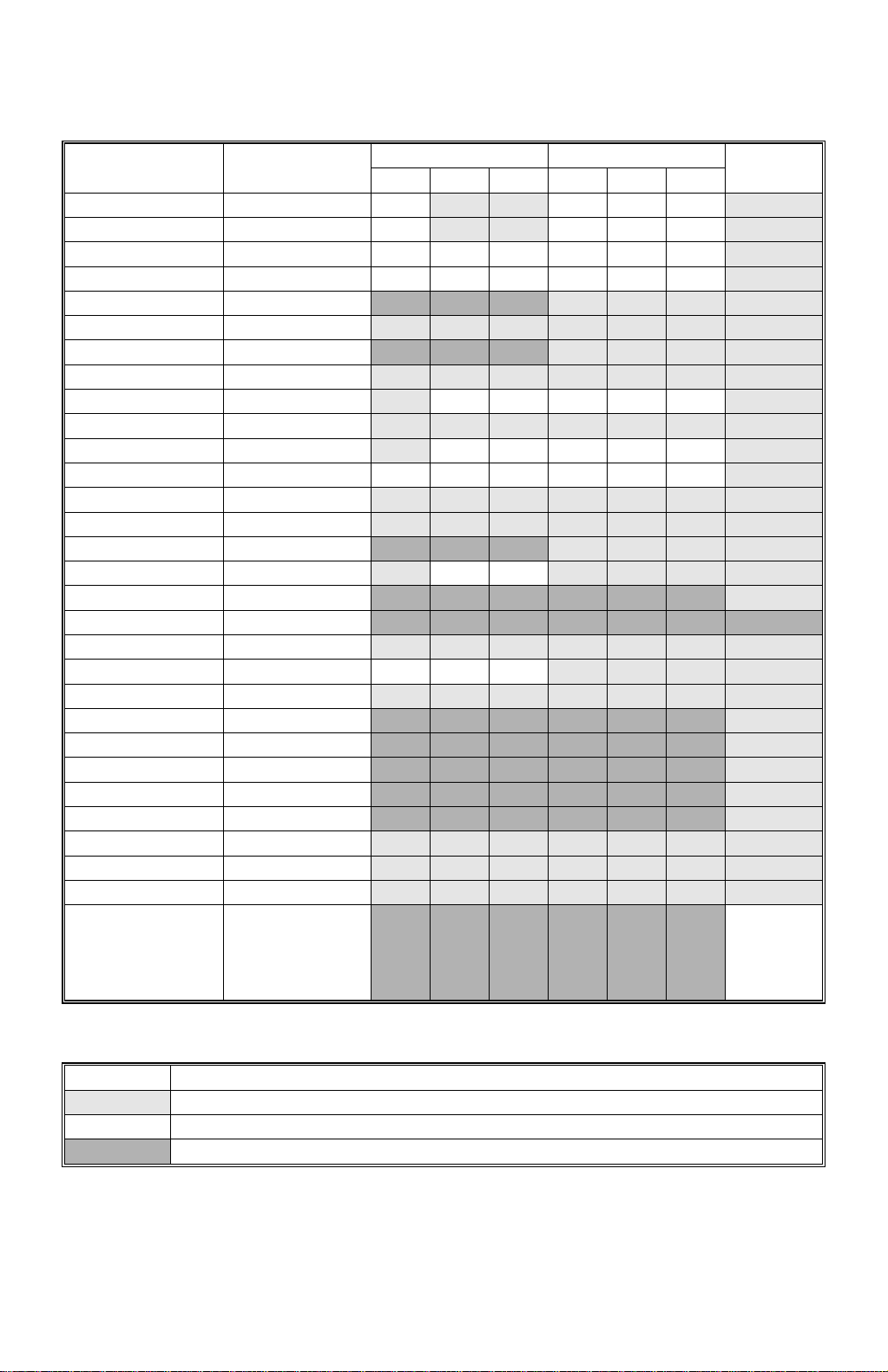
1.1.2 SUPPORTED PAPER SIZES
Paper Size (W x L)
Ledger 11 x 17” Y Y
Legal 8.5 x 14“ Y Y
Tray 1 Tray 2/3
NA EU Asia NA EU Asia
#
#
#
Y
Y
YYY Y
#
YYY Y
By-pass
Letter SEF 8.5 x 11” Y Y Y Y Y Y Y
Letter LEF 11 x 8.5” Y Y Y Y Y Y Y
Half Letter SEF 5.5 x 8.5” N N N Y
Half Letter LEF 8.5 x 5.5” Y
#
#
Y
#
Y
Executive SEF 7.25 x 10.5” N N N Y
Executive LEF 10.5 x 7.25” Y
A3 297 x 420 mm Y
B4 257 x 364 mm Y
A4 SEF 210 x 297 mm Y
#
#
#
#
#
Y
#
Y
YYYYY Y
#
Y
#
Y
YYYYY Y
#
#
Y
#
#
Y
#
Y
#
Y
#
Y
#
Y
#
Y
#
Y
#
Y
#
Y
#
Y
#
Y
#
Y
Y
Y
Y
Y
Y
A4 LEF 297 x 210 mm Y Y Y Y Y Y Y
B5 SEF 182 x 257 mm Y
B5 LEF 257 x 182 mm Y
#
#
A5 SEF 148 x 210 mm N N N Y
A5 LEF 210 x 148 mm Y
#
#
Y
#
Y
#
Y
#
Y
YYY
#
Y
#
Y
#
#
#
Y
#
Y
#
Y
#
Y
#
Y
#
Y
#
Y
#
Y
Y
Y
Y
Y
A6 SEF 105 x 148 mm N N N N N N Y
A6 LEF 148 x 105 mm N N N N N N N
Folio 8.25 x 13” Y
#
Foolscap 8.5 x 13” Y Y Y Y
F 8 x 13” Y
#
#
Y
#
Y
#
Y
#
Y
#
Y
#
#
Y
#
Y
#
Y
#
Y
#
Y
#
Y
#
Y
Y
Y
Y
Com10 Env 4.125 x 9.5” N N N N N N Y
Monarch Env 3.875 x 7.5” N N N N N N Y
C6 Env 114 x 162 mm N N N N N N Y
C5 Env 162 x 229 mm N N N N N N Y
DL Env 110 x 220 mm N N N N N N Y
8K 267 x 390 mm Y
16K SEF 195 x 267 mm Y
16K LEF 267 x 195 mm Y
Custom [Minimum]
#
#
#
N N N N N N Y
#
Y
#
Y
#
Y
#
Y
#
Y
#
Y
#
Y
#
Y
#
Y
#
Y
#
Y
#
Y
#
Y
#
Y
#
Y
Y
Y
Y
90 x 148 mm
[Maximum]
297 x 432 mm
#
#
#
#
#
#
#
#
#
#
#
#
#
#
#
#
#
#
#
#
#
#
#
#
#
#
#
#
C
Keys:
Y Supported. The paper size sensor detects this paper size.
#
Y
C
Y
Supported. The user has to select the correct paper size for the tray.
Supported. The user has to enter the width and length of the paper.
N Not supported.
NA: North America version, EU: Europe version
1-2
31 May, 1999 OVERALL MACHINE INFORMATION
1.2 SOFTWARE ACCESSORIES
The printer drivers and utility software are provided on one CD-ROM. An auto-run
installer allows you to select which components to install. The service tools are not
provided on the CD-ROM.
1.2.1 PRINTER DRIVERS
Printer Language Windows 3.1x Windows 95/98 W indows NT4.0 Macintosh
PCL 6 Yes Yes Yes No
PCL 5e Yes Yes Yes No
PS3 Yes Yes Yes Yes
Overall
Information
NOTE:
1) The printer drivers for Windows NT 4.0 are only for the Intel x86
platform. There is no Windows NT 4.0 printer driver for PowerPC, Alpha,
or MIPS platforms.
2) The PS3 drivers are all genuine AdobePS drivers. A PPD file for each
operating system is provided with the driver.
3) The PS3 drivers for Macintosh support Mac OS 7.1 or later versions.
4) The PS3 drivers for Windows 3.1x and Windows NT4.0 do not support
the “Proof Print” function.
1.2.2 UTILITY SOFTWARE
Software Description
Afga Font Manager
(Win3.1x, 95/98, NT4)
Aficio Manager for Admin
(Win 95/98, NT4)
Aficio Manager for Client
(Win95/98, NT4)
Multi-Direct Print
(Win95/98, NT4)
A font management utility with screen fonts for the printer.
A printer management utility for network administrators. NI B
setup utilities are also available.
A printer management utility for client users.
A utility for peer-to-peer printing over a NetBEUI or TCP/IP
network.
1.2.3 SERVICE TOOLS
Software Description
NBTFTP NIB firmware update utility for use on a NetBEUI network.
This utility is not on the Driver and Utilities CD-ROM; it is
issued separately as a service tool
1-3
MACHINE OVERVIEW 31 May, 1999
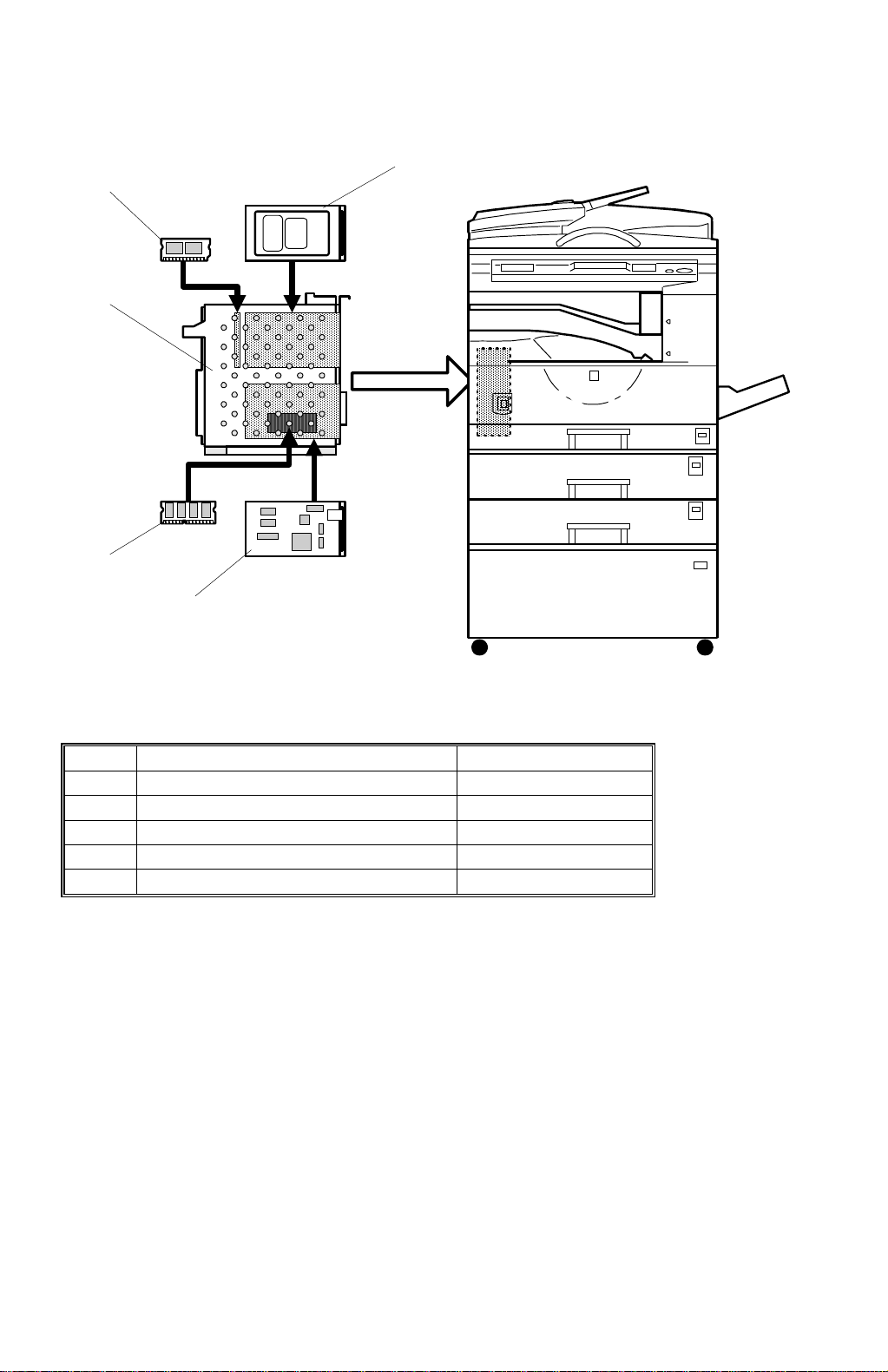
1.3 MACHINE OVERVIEW
[B]
[C]
[A]
[D]
[E]
Ref. Component Machine Code
A Printer Controller B305
B Hard Disk (option) G690
C PS3 Module (option) B308
D SDRAM Module (option) G688
E Network Interface Board (option) B307
B305V501.WMF
1-4
31 May, 1999 OVERALL MACHINE INFORMATION
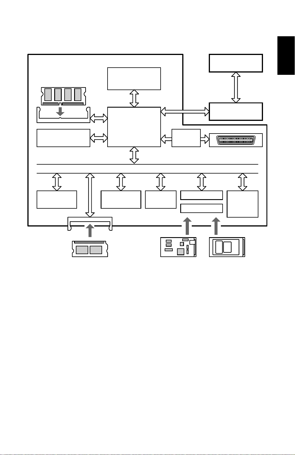
1.4 BLOCK DIAGRAM
SDRAM DIMM
(Option)
32MB or 64MB
SDRAM
(16MB)
Code ROM
(4MB Flash)
Controller
CPU
NEC VR4310
167MHz
ASIC
Rocky-R
DATA/ADDRESS BUS
Font ROM
(1MB Mask)
EEPROM
(8kB)
Parallel I/F
Controller
Option Bus I/F
Option Bus I/F
BiCU
Mother Board
IEEE1284 Port
(ECP)
Flash
Memory
Card I/F
Overall
Information
PS3 DIMM
(Option)
8MB Flash
Ethernet NIB
(Option)
10BaseT/100BaseTX
HDD
(Option)
1.6GB
B305V502.WMF
The controller board contains a CPU (NEC VR4310) and an ASIC (Rocky-R). The
ASIC controls the main memory (SDRAM), engine interface, ROM interface,
IEEE1284 parallel interface, two option bus interfaces for the NIB and HDD, and an
IC card interface fo r upgrading firmware.
There is one optional memory socket that can have either a 32MB or a 64MB
SDRAM DIMM module to increase RAM capacity and enable RAM collation. With
the 64MB SDRAM module, the RAM capacity is increased to 80MB. There is
another memory socket for the optional PS3 DIMM.
The two option bus interfaces allow the user to install an Ethernet NIB and a hard
disk drive (allows the Proof Print, Disk Collation, and font and form download
features).
The flash memory card interface allows the firmware for the controller, PostScript,
and NIB to be updated.
1-5

31 May, 1999 DETAILED SECTIONS DESCRIPTIONS
2. DETAILED SECTIONS DESCRIPTIONS
2.1 ENGINE FUN CTI ONS
2.1.1 IMAGE DATA PROCESSING
The controller uses the engine’s FCI (Fine Character Image) function for smoothing
and toner saving mode, but these two functions do not work at the same time.
When toner saving mode is enabled, edge smoothing is automatically disabled.
The memory circuit in the engine (MSU) is not used for printing from the controller.
2.1.2 PRINT PRIORITY AND INTERLEAVING
[User Tools] – [System Settings] – [Print Priority] defines how the copy, fax and
printer applications share a single print engine.
Detailed
Descriptions
NOTE:
“[User Tools] – [System Settings] – [Print Priority]” indicates that you press
the System Tools key, select System from the menu, then select “Print
Priority” from the next menu.
Display Priority
A print request from the application (copy, fax, or printer) now displayed on the
LCD has the highest priority. For example, the machine is in the middle of a large
copy run, and a user wants to print a document from a computer immediately. In
this case, pressing the Printer key to switch the LCD display to Printer mode will
interrupt the copy run and print the document from the computer, and the copy run
will resume after the document has been printed. If the LCD display stays in Copy
mode, the user will have to wait until the copy run finishes.
Note that the Interrupt key on the operation panel does not work like the Printer key
in the above example. The Interrupt key is for interrupting a copy run to do another
copy operation.
Copier, Fax or Printer
The selected application has the highest priority, regardless of which mode the
LCD is in. If there are multiple print requests to the print engine, the selected
application will print first. Other applications have to wait until the selected
application finishes pri nting .
2-1

ENGINE FUNCTIONS 31 May, 1999
Interleave
All the applications have the same priority. An application can print even while
another application is using the printer engine. If there are multiple print requests to
the print engine, the engine will adjust its print priorities and the sequence of
printed pages.
For example, if a received fax message and a copy job are waiting for printing, the
machine prints 5 pages of the fax, then 5 pages of the copy job, then the next 5
pages of the fax, and so on.
Copier SP mode 5-951 determines the number of pages that are printed from one
job before switching over to the next. The default is 5 pages.
NOTE:
Using the Inte rleave function is not recommended if the m achine does not
have multiple output trays. This is because the printouts from copy, fax,
and printer applications may be mixed up in a single output tray if the
Interleave function is enabled.
2-2
31 May, 1999 DETAILED SECTIONS DESCRIPTIONS
2.2 CONTROLLER FUNCTIONS
2.2.1 PAPER SIZE DETECTION AND SELECTION
The controller uses the paper sizes detected by the print engine for trays 1, 2 and
3. For the by-pass tray, the user has to specify a paper size using the Job Control
menu in the Printer User Tools. Refer to section 1.1.2 for details on supported
paper sizes.
When the printer controller receives a print job, the controller uses the paper size
specified in the PJL, PCL, or PS commands for printing.
2.2.2 PAPER SOURCE SELECTION
Auto Tray Select
Tray 1
Tray 2 (optional)
Tray 3 (optional)
The controller searches for the specified paper size, starting from Tray 1, and uses
the first tray that has the specified paper size. If the selected tray is pulled out or
paper runs out during printing, the controller searches for another tray with the
specific paper size and if found, automatically switches to it. If the controller cannot
find another paper tray with the specified paper size, printing stops and the LCD
displays the message “Add Paper to Tray 1”.
Start of Tray Search
B305D501.WMF
Detailed
Descriptions
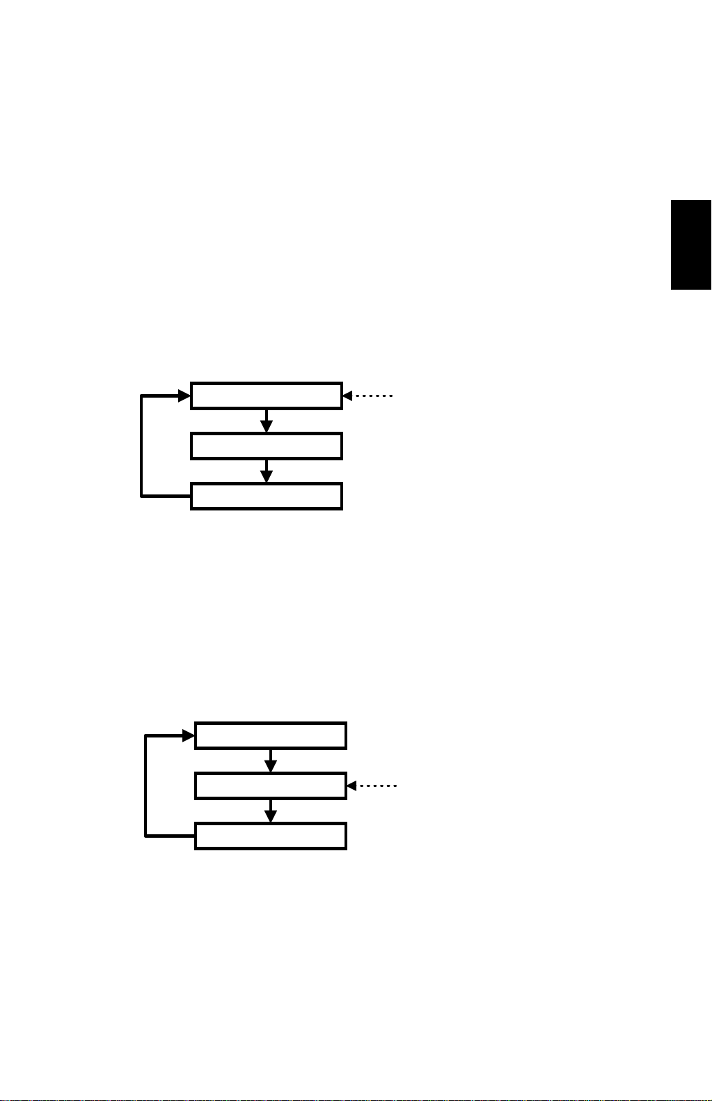
Manual Tray Select
Tray 1
Tray 2 (optional)
Tray 3 (optional)
When the prin ter driver specif ies a tray, the selec ted tray becomes the first tray
checked at the start of the tray search. If the selected tray does not have the size of
paper specified by the driver, the controller searches the other trays for the same
paper size.
NOTE:
Tray Priority in the Job Control menu does not specify the start of the tray
search, but specifies the paper size in the selected tray as the default
paper size.
2-3
Start of Tray Search
(Tray selected by the driver)
B305D502.WMF

CONTROLLER FUNCTIONS 31 May, 1999
Tray Lock
If Tray Lock is enabled for a tray, the controller does not use the “locked” tray in the
tray search process. If a tray has, for example, coloured A4 size paper for fax
prints, enable tray lock for that tray so that the controller does not select the tray for
printing.
If the printer driver selects a “locked” tray, the controller uses the tray for printing
only when the specified paper size matches the actual paper size in the tray.
By-pass Tray
The by-pass tray is not part of the automatic tray search. To print from the by-pass
tray, the user has to select the by-pass tray. Even if the by-pass tray is empty, the
controller will not switch to another tray; the message on the LCD asks the user to
add paper to the by-pass tray.
NOTE:
Collation is disabled when the by-pass tray is selected.
Paper Size Mismatch
When the controller could not find the specified paper size in an y of the trays, the
machine displays an error message, e.g., “Load 8 ½ x 11”.
Then the user can either load the requested paper size in a tray or select another
tray, e.g., a tray that contains A4 size paper, by pressing the “Form Feed” key.
The controller will print the job if the specif ied paper size is detected in a tray, or if
the user presses the Enter key after selecting a tray.
2.2.3 OUTPUT TRAY SELECTION
Output Tray Priority in the System User Tools specifies the default paper output
tray for each application. If a print job does not specify an output tray or the driver
specifies the Default Tray, the default tray is used.
If the driver specifies an output tray, this overrides the default tray setting in the
user tools.
If the option one-bin tray is selected but it has an error, the standard output tray is
used.
2-4

31 May, 1999 DETAILED SECTIONS DESCRIPTIONS
2.2.4 COLLATION (SORT)
When the co ntroller has either an optional SDRAM DIMM o r an optional HDD
installed, collation is enabled.
If the memory or HDD becomes full while storing a job tha t uses collation, the
controller prints the pages that have been stored for collation, empties the memory
or HDD, then continues printing the rest of the pages with collation.
Memory Capacity Collation Maximum Pages Note
16MB (standard) Not possible
48MB (with 32MB) Possible 30 pages Note 1)
80MB (with 64MB) Possible 50 pages Note 1)
With HDD Possible 1500 pages Note 2)
Detailed
Descriptions
NOTE:
1) The number of pages is calculated using a sample MS-Word document
that contains 5,000 characters of plain text. The sample document takes
409.6kB of memory space per page.
If the document is more complex, the memory can hold fewer pages. If
the document is simpler, e.g., 1,000 characters per page, the memory
can hold more pages.
2) This is the maximum number of pages that the controller can handle.
If the document is more complex, the HDD can ho ld fewer pages. Even
if the document is simpler, e.g., 1,000 characters per page, the HDD
cannot hold more than 1,500 pages.
To calculate the pages using the same document as specified in Note 1,
the HDD can hold up to 1,250 pages.
About 500 MB of disk space is used for collation.
2-5
 Loading...