

Page 1
STINGER-C1
(Machine Code: A250)
SERVICE MANUAL
Subject to change
Ricoh Technical Service
May 17th, 1999
Page 2

I
IMPORTANT SAFETY NOTICES
PREVENTION OF PHYSICAL INJURY
1. Before disassembling or assembling parts of the copier and peripherals,
make sure that the copier power cord is unplugged.
2. The wall outlet should be near the copier and easily accessible.
3. Note that some components of the copier and the paper tray unit are
supplied with electrical voltage even if the main power switch is turned off.
4. If any adjustment or operation check has to be made with exterior covers off
or open while the main switch is turned on, keep hands away from electrified
or mechanically driven components.
5. If the “Start” key is pressed before the copier completes the warm-up period
(the “Start” key starts blinking red and green alternatively), keep hands away
from the mechanical and the electrical components as the copier starts
making copies as soon as the warm-up period is completed.
6. The inside and the metal parts of the fusing unit become extremely hot while
the copier is operating. Be careful to avoid touching those components with
your bare hands.
HEALTH SAFETY CONDITIONS
1. Always replace the ozone filters with the specified ones at the specified
intervals.
2. Toner is non-toxic, but if you get it in your eyes by accident, it may cause
temporary eye discomfort. Try to remove with eye drops or flush with water
as first aid. If unsuccessful, get medical attention.
OBSERVANCE OF ELECTRICAL SAFETY STANDARDS
1. The copier and its peripherals must be installed and maintained by a
customer service representative who has completed the training course on
those models.
2. The danger of explosion exists if batteries on the FCU and JBIG are
incorrectly replaced. Replace only with the same or an equivalent type
recommended by the manufacturer. Discard used batteries in accordance
with the manufacturer’s instructions.
Page 3

SAFETY AND ECOLOGICAL NOTES FOR DISPOSAL
1. Do not incinerate AIO cartridge. Toner dust may ignite suddenly when
exposed to and open flame.
2. Dispose of used AIO cartridge in accordance with local regulations. (This is
non-toxic supplies.)
3. Dispose of replaced parts in accordance with local regulations.
4. When keeping used lithium batteries in or der to dispos e of them later, do not
put more than 100 batteries per sealed box. Storing larger numbers or not
sealing them apart may lead to chemical reactions and heat build-up.
LASER SAFETY
The Center for Devices and Radiological Health (CDRH) prohibits the repair of
laser-based optical units in the field. The optical housing unit can only be repaired
in a factory or at a location with the requisite equipment. The laser subsystem is
replaceable in the field by a qualified Customer Engineer. The laser chassis is not
repairable in the field. Customer engineers are therefore directed to return all
chassis and laser subsystems to the factory or service depot when replacement of
the optical subsystem is required.
WARNING
I
Use of controls, or adjustment, or performance of procedures other than
those specified in this manual may result in hazardous radiation exposure.
WARNING FOR LASER UNIT
I
WARNING: Turn off the main switch before attempting any of the
procedures in the Laser Unit section. Laser beams can
seriously damage your eyes.
CAUTION MARKING:
Page 4

TABLE OF CONTENTS
1. OVERALL MACHINE INFORMAT ION........................................1-1
1.1 SPECIFICATIONS.................................................................................... 1-1
1.2 MACHINE CONFIGURATION.................................................................. 1-5
1.3 PAPER PATH........................................................................................... 1-6
1.4 MECHANICAL COMPONENT LAYOUT................................................... 1-7
1.5 ELECTRICAL COMPONENT DESCRIPTIONS........................................ 1-8
1.5.1 COPIER ENGINE ............................................................................ 1-8
1.6 DRIVE LAYOUT ..................................................................................... 1-11
1.7 COPY PROCESS................................................................................... 1-12
1.7.1 OVERVIEW ................................................................................... 1-12
1.8 BOARD STRUCTURE............................................................................ 1-14
1.8.1 OVERVIEW ................................................................................... 1-14
1.8.2 DESCRIPTION .............................................................................. 1-15
2. DETAILED SECTION DESCRIPTIONS.......................................2-1
2.1 SCANNING............................................................................................... 2-1
2.1.1 OVERVIEW ..................................................................................... 2-1
2.1.2 SCANNER DRIVE ........................................................................... 2-2
2.1.3 ORIGINAL SIZE DETECTION IN PLATEN MODE.......................... 2-3
2.2 IMAGE PROCESSING .............................................................................2-5
2.2.1 OVERVIEW ..................................................................................... 2-5
2.2.2 SBU (SENSOR BOARD UNIT)........................................................ 2-7
2.2.3 AUTO IMAGE DENSITY (ADS)....................................................... 2-8
2.2.4 IMAGE PROCESSING UNIT (IPU).................................................. 2-9
2.2.5 MEMORY CONTROLLER AND EXTENDED MEMORY
BOARD (EMB)............................................................................... 2-20
2.2.6 VIDEO CONTROL UNIT (VCU)..................................................... 2-21
2.2.7 IMAGE PROCESSING SUMMARY............................................... 2-23
2.3 LASER EXPOSURE............................................................................... 2-33
2.3.1 OVERVIEW ................................................................................... 2-33
2.3.2 OPTICAL PATH............................................................................. 2-34
2.3.3 AUTO POWER CONTROL (APC) ................................................. 2-35
2.3.4 LD SAFETY SWITCH.................................................................... 2-36
2.4 ALL-IN-ONE CARTRIDGE (AIO CARTRIDGE)...................................... 2-37
2.4.1 OVERVIEW ................................................................................... 2-37
2.4.2 DRIVE............................................................................................ 2-38
2.4.3 DRUM CHARGE............................................................................ 2-39
2.4.4 DEVELOPMENT............................................................................ 2-40
2.4.5 DRUM CLEANING......................................................................... 2-43
2.5 IMAGE TRANSFER AND PAPER SEPARATION.................................. 2-44
2.5.1 OVERVIEW ................................................................................... 2-44
2.5.2 TRANSFER CURRENT SETTINGS.............................................. 2-45
2.5.3 TRANSFER ROLLER CLEANING................................................. 2-46
2.6 PAPER FEED.........................................................................................2-47
i
Page 5

2.6.1 OVERVIEW ................................................................................... 2-47
2.6.2 BUILT-IN TRAY............................................................................. 2-48
2.6.3 BY-PASS TRAY............................................................................. 2-51
2.6.4 PAPER REGISTRATION............................................................... 2-53
2.6.5 MISFEED DETECTION................................................................. 2-54
2.7 IMAGE FUSING...................................................................................... 2-57
2.7.1 OVERVIEW ................................................................................... 2-57
2.7.2 FUSING UNIT DRIVE.................................................................... 2-58
2.7.3 PRESSURE ROLLER/PAPER EXIT.............................................. 2-59
2.7.4 FUSING UNIT DRIVE RELEASE................................................... 2-59
2.7.5 FUSING TEMPERATURE CONTROL........................................... 2-60
2.7.6 OVERHEAT PROTECTION........................................................... 2-63
2.7.7 ENERGY SAVER MODE............................................................... 2-63
3. INSTALLA T ION...........................................................................3-1
3.1 INSTALLATION REQUIREMENTS .......................................................... 3-1
3.1.1 ENVIRONMENT ..............................................................................3-1
3.1.2 MACHINE LEVEL............................................................................ 3-2
3.1.3 MINIMUM SPACE REQUIREMENTS.............................................. 3-3
3.1.4 POWER REQUIREMENTS.............................................................. 3-4
3.2 COPIER INSTALLATION.......................................................................... 3-5
3.2.1 ACCESSORY CHECK..................................................................... 3-5
3.2.2 COPIER INSTALLATION PROCEDURE......................................... 3-6
3.3 ADF INSTALLATION.............................................................................. 3-10
3.3.1 ACCESSORY CHECK................................................................... 3-10
3.3.2 ADF INSTALLATION PROCEDURE ............................................. 3-11
3.4 PAPER TRAY UNIT (1 TRAY) INSTALLATION ..................................... 3-14
3.4.1 ACCESSORY CHECK................................................................... 3-14
3.4.2 PAPER TRAY UNIT INSTALLATION PROCEDURE..................... 3-15
3.5 PAPER TRAY UNIT (2 TRAYS) INSTALLATION................................... 3-18
3.5.1 ACCESSORY CHECK................................................................... 3-18
3.5.2 PAPER TRAY UNIT INSTALLATION PROCEDURE..................... 3-19
3.6 1-BIN SORTER INSTALLATION............................................................ 3-23
3.6.1 ACCESSORY CHECK................................................................... 3-23
3.6.2 1-BIN SORTER INSTALLATION PROCEDURE............................ 3-24
3.7 PLATEN COVER INSTALLATION.......................................................... 3-29
3.7.1 ACCESSORY CHECK................................................................... 3-29
3.7.2 PLATEN COVER INSTALLATION PROCEDURE......................... 3-29
3.8 EXTENDED MEMORY BOARD INSTALLATION................................... 3-30
3.8.1 ACCESSORY CHECK................................................................... 3-30
3.8.2 EXTENDED MEMORY BOARD INSTALLATION
PROCEDURE................................................................................ 3-31
3.9 DRUM HEATER INSTALLATION (OPTION).......................................... 3-32
3.10 OPTICS ANTI-CONDENSATION HEATER INSTALLATION
(OPTION).............................................................................................. 3-33
3.11 TRAY HEATER INSTALLATION.......................................................... 3-34
ii
Page 6

4. SERVICE TABLES......................................................................4-1
4.1 GENERAL CAUTION................................................................................ 4-1
4.1.1 AIO CARTRIDGE (ALL-IN-ONE CARTRIDGE)............................... 4-1
4.1.2 TRANSFER ROLLER UNIT............................................................. 4-1
4.1.3 SCANNER UNIT..............................................................................4-1
4.1.4 LASER UNIT.................................................................................... 4-2
4.1.5 FUSING UNIT.................................................................................. 4-2
4.1.6 PAPER FEED.................................................................................. 4-2
4.1.7 OTHERS.......................................................................................... 4-2
4.2 SERVICE PROGRAM MODE................................................................... 4-3
4.2.1 SERVICE PROGRAM MODE OPERATION.................................... 4-3
4.1.2 SERVICE PROGRAM MODE TABLES........................................... 4-4
4.1.3 TEST PATTERN PRINTING (SP5-902)......................................... 4-38
4.1.4 INPUT CHECK (SP5-803)............................................................. 4-39
4.1.5 OUTPUT CHECK (SP5-804)......................................................... 4-44
4.1.6 COPY JAM HISTORY DISPLAY (SP7-903) .................................. 4-46
4.1.7 ORIGINAL JAM HISTORY DISPLAY (SP7-905)........................... 4-47
4.1.8 SYSTEM PARAMETER AND DATA LISTS (SP5-992).................. 4-48
4.1.9 MEMORY ALL CLEAR (SP5-801)................................................. 4-49
4.1.10 PROGRAM UPLOAD/DOWNLOAD............................................. 4-50
4.1.11 NVRAM DATA DOWNLOAD....................................................... 4-53
4.1.12 APS AND PLATEN/DF COVER SENSOR OUTPUT DISPLAY
(SP4-301) .................................................................................... 4-55
4.1.13 DF APS SENSOR OUTPUT DISPLAY (SP6-901)....................... 4-56
4.1.14 DISPLAY LANGUAGE (SP5-808)................................................ 4-57
4.1.15 SERIAL NUMBER INPUT (SP5-811)........................................... 4-57
4.3 USER TOOLS......................................................................................... 4-58
4.1.1 HOW TO ENTER AND EXIT USER TOOLS..................................4-58
4.1.2 USER TOOLS TABLE ................................................................... 4-58
4.4 LEDS...................................................................................................... 4-60
4.5 SPECIAL TOOLS AND LUBRICANTS ................................................... 4-60
4.5.1 SPECIAL TOOLS........................................................................... 4-60
4.5.2 LUBRICANTS................................................................................ 4-60
5. PREVENTIVE MAINTENANCE SCHEDULE...............................5-1
5.1 PM TABLE................................................................................................ 5-1
5.2 HOW TO CLEAR THE MAINTENANCE COUNTER................................ 5-2
6. REPLACEMENT AND ADJUSTMENT ........................................ 6-1
6.1 EXTERIOR REMOVAL............................................................................. 6-1
6.1.1 REAR COVER................................................................................. 6-1
6.1.2 COPY TRAY.................................................................................... 6-1
6.1.3 LEFT COVER.................................................................................. 6-1
6.1.4 FRONT COVER............................................................................... 6-2
6.1.5 UPPER RIGHT COVER................................................................... 6-3
6.1.6 LOWER RIGHT COVER.................................................................. 6-3
6.1.7 RIGHT SMALL COVER................................................................... 6-3
6.1.8 OPERATION PANEL....................................................................... 6-4
iii
Page 7

6.2 SCANNER................................................................................................ 6-5
6.2.1 EXPOSURE GLASS REMOVAL...................................................... 6-5
6.2.2 LENS BLOCK REMOVAL................................................................ 6-7
6.2.3 EXPOSURE LAMP REPLACEMENT.............................................. 6-8
6.2.4 1ST SCANNER ALIGNMENT ADJUSTMENT................................. 6-9
6.2.5 2ND SCANNER POSITION ADJUSTMENT.................................. 6-10
6.3 LASER UNIT........................................................................................... 6-11
6.3.1 CAUTION DECAL LOCATIONS.................................................... 6-11
6.3.2 LASER UNIT/TONER SHIELD GLASS REMOVAL....................... 6-12
6.3.3 LD UNIT/LASER SYNCHRONIZATION DETECTOR
REMOVAL ..................................................................................... 6-13
6.3.4 EXIT TRAY PAPER SENSOR REMOVAL..................................... 6-13
6.3.5 POLYGONAL MIRROR MOTOR REMOVAL................................. 6-14
6.3.6 LASER UNIT ALIGNMENT ADJUSTMENT................................... 6-15
6.4 IMAGE TRANSFER................................................................................ 6-16
6.4.1 TRANSFER ROLLER REMOVAL.................................................. 6-16
6.5 FUSING.................................................................................................. 6-17
6.5.1 FUSING UNIT REMOVAL ............................................................. 6-17
6.5.2 HOT ROLLER, FUSING LAMP AND THERMOFUSE
REPLACEMENT............................................................................ 6-18
6.5.3 PRESSURE ROLLER REPLACEMENT........................................ 6-20
6.5.4 FUSING THERMISTOR REPLACEMENT..................................... 6-21
6.5.5 HOT ROLLER STRIPPER PAWL REPLACEMENT...................... 6-22
6.6 PAPER FEED.........................................................................................6-23
6.6.1 PAPER FEED ROLLER REPLACEMENT..................................... 6-23
6.6.2 FRICTION PAD REPLACEMENT.................................................. 6-24
6.6.3 STANDARD TRAY PAPER FEED CLUTCH REPLACEMENT...... 6-25
6.6.4 VERTICAL TRANSPORT ROLLER/SENSOR/
CLUTCH REPLACEMENT ............................................................ 6-26
6.6.5 BY-PASS FEED ROLLER REPLACEMENT.................................. 6-27
6.6.6 BY-PASS FEED FRICTION PAD REPLACEMENT....................... 6-28
6.6.7 BY-PASS FEED SENSOR REPLACEMENT................................. 6-29
6.6.8 BY-PASS TRAY REMOVAL ..........................................................6-30
6.6.9 BY-PASS FEED PAPER WIDTH SENSOR REMOVAL ................ 6-31
6.6.10 REGISTRATION ROLLER REMOVAL........................................ 6-32
6.6.11 REGISTRATION SENSOR REPLACEMENT.............................. 6-33
6.6.12 TONER END SENSOR REPLACEMENT.................................... 6-34
6.7 OTHERS................................................................................................. 6-35
6.7.1 MAIN MOTOR/GEAR BOX REPLACEMENT................................ 6-35
6.7.2 IOB (INPUT OUTPUT BOARD) REPLACEMENT ......................... 6-36
6.7.3 BICU (BASE-ENGINE IMAGE CONTROL UNIT)
REPLACEMENT............................................................................ 6-37
6.7.4 POWER SUPPLY UNIT AND B/C/T POWER PACK
REPLACEMENT............................................................................ 6-38
6.8 STANDARD WHITE DENSITY ADJUSTMENT...................................... 6-39
6.9 COPY ADJUSTMENT PRINTING/SCANNING....................................... 6-40
6.9.1 PRINTING...................................................................................... 6-40
6.9.2 SCANNING.................................................................................... 6-42
6.9.3 ADF IMAGE ADJUSTMENT.......................................................... 6-44
iv
Page 8

7. TROUBLESHOOTING.................................................................7-1
7.1 SERVICE CALL CONDITIONS................................................................. 7-1
7.1.1 SUMMARY....................................................................................... 7-1
7.1.2 SC CODE DESCRIPTIONS............................................................. 7-2
7.2 BLOWN FUSE TABLE............................................................................ 7-10
7.3 ELECTRICAL COMPONENT DEFECTS................................................ 7-10
7.3.1 SWITCHES.................................................................................... 7-10
7.3.2 SENSORS..................................................................................... 7-11
OPTIONS
DOCUMENT FEEDER (A859)
1. OVERALL INFORMATION.................................................... A859-1
1.1 SPECIFICATIONS..............................................................................A859-1
1.2 MECHANICAL COMPONENT LAYOUT.............................................A859-2
1.3 ELECTRICAL COMPONENT LAYOUT..............................................A859-3
1.4 ELECTRICAL COMPONENT DESCRIPTION....................................A859-4
1.5 DRIVE LAYOUT .................................................................................A859-5
2. DETAILED SECTION DESCRIPTIONS.................................A859-6
2.1 ORIGINAL SIZE DETECTION............................................................A859-6
1.2 PICK-UP AND SEPARATION.............................................................A859-8
1.3 ORIGINAL TRANSPORT AND EXIT MECHANISM ...........................A859-9
1.4 STAMP .............................................................................................A859-10
1.5 TIMING CHARTS .............................................................................A859-11
1.5.1 A4 SIDEWAYS.........................................................................A859-11
1.5.2 A4 SIDEWAYS, STAMP MODE...............................................A859-12
1.6 JAM DETECTION.............................................................................A859-13
1.7 OVERALL ELECTRICAL CIRCUIT...................................................A859-14
3. REPLACEMENT AND ADJUSTMENT................................A859-15
3.1 FEED UNIT REMOVAL....................................................................A859-15
3.2 SEPARATION ROLLER REPLACEMENT........................................A859-15
3.3 PICK-UP ROLLER REPLACEMENT................................................ A859-16
3.4 FEED BELT REPLACEMENT..........................................................A859-16
3.5 ORIGINAL SET SENSOR REPLACEMENT.....................................A859-17
3.6 ORIGINAL WIDTH/LENGTH/TRAILING EDGE SENSOR
REPLACEMENT...............................................................................A859-18
3.7 ORIGINAL EXIT TRAY/FRONT COVER/REAR COVER
REMOVAL........................................................................................A859-19
3.8 FEED COVER OPEN SENSOR/DF OPEN SENSOR
REPLACEMENT...............................................................................A859-19
3.9 FEED CLUTCH/PICK-UP SOL/TRANSPORT MOTOR
REPLACEMENT...............................................................................A859-20
3.10 DF FEED COVER REMOVAL........................................................A859-21
3.11 REGISTRATION SENSOR REPLACEMENT.................................A859-21
3.12 STAMP SOLENOID REPLACEMENT............................................A859-22
v
Page 9

PAPER TRAY UNIT (A860)
1. OVERALL MACHINE INFORMAT ION..................................A860-1
1.1 SPECIFICATIONS..............................................................................A860-1
1.2 MECHANICAL COMPONENT LAYOUT.............................................A860-2
1.3 ELECTRICAL COMPONENT LAYOUT..............................................A860-3
1.4 ELECTRICAL COMPONENT DESCRIPTION....................................A860-4
1.5 DRIVE LAYOUT .................................................................................A860-5
2. DETAILED DESCRIPTIONS .................................................A860-6
2.1 PAPER FEED AND SEPARATION MECHANISM..............................A860-6
2.2 PAPER LIFT MECHANISM................................................................A860-7
2.3 PAPER END DETECTION.................................................................A860-9
2.4 PAPER HEIGHT DETECTION.........................................................A860-10
1.5 PAPER SIZE DETECTION...............................................................A860-12
1.6 SIDE AND END FENCES.................................................................A860-13
3. REPLACEMENT AND ADJUSTMENT................................A860-14
3.1 FEED ROLLER REPLACEMENT.....................................................A860-14
3.2 TRAY MAIN BOARD REPLACEMENT.............................................A860-15
3.3 TRAY MOTOR REPLACEMENT......................................................A860-15
3.4 RELAY CLUTCH REPLACEMENT...................................................A860-16
3.5 UPPER PAPER FEED CLUTCH REPLACEMENT ..........................A860-17
3.6 LOWER PAPER FEED CLUTCH REPLACEMENT..........................A860-18
3.7 LIFT MOTOR REPLACEMENT........................................................A860-19
3.8 PAPER END SENSOR REPLACEMENT.........................................A860-20
3.9 VERTICAL TRANSPORT SENSOR REPLACEMENT ..................... A860-20
3.10 PAPER SIZE SWITCH REPLACEMENT........................................A860-21
PAPER TRAY UNIT (A861)
1. OVERALL MACHINE INFORMAT ION..................................A861-1
1.1 SPECIFICATIONS..............................................................................A861-1
1.2 MECHANICAL COMPONENT LAYOUT.............................................A861-2
1.3 ELECTRICAL COMPONENT LAYOUT..............................................A861-3
1.4 ELECTRICAL COMPONENT DESCRIPTION....................................A861-4
1.5 DRIVE LAYOUT .................................................................................A861-5
2. DETAILED DESCRIPTIONS .................................................A861-6
2.1 PAPER FEED AND SEPARATION ....................................................A861-6
2.2 PAPER LIFT MECHANISM................................................................A861-7
2.3 PAPER END DETECTION .................................................................A861-9
2.4 PAPER HEIGHT DETECTION.........................................................A861-10
2.5 PAPER SIZE DETECTION...............................................................A861-12
2.6 SIDE AND END FENCES.................................................................A861-13
vi
Page 10

3. REPLACEMENT AND ADJUSTMENT................................A861-14
3.1 FEED ROLLER REPLACEMENT.....................................................A861-14
3.2 TRAY MAIN BOARD REPLACEMENT.............................................A861-15
3.3 TRAY MOTOR REPLACEMENT......................................................A861-15
3.4 TRAY MOTOR REPLACEMENT......................................................A861-16
3.5 LIFT MOTOR REPLACEMENT........................................................A861-17
3.6 PAPER END SENSOR REPLACEMENT.........................................A861-18
3.7 PAPER SIZE SWITCH REPLACEMENT..........................................A861-18
1-BIN SORTER (A869)
1. OVERALL INFORMATION.................................................... A869-1
1.1 SPECIFICATIONS..............................................................................A869-1
1.2 MECHANICAL COMPONENT LAYOUT.............................................A869-2
1.3 ELECTRICAL COMPONENT LAYOUT..............................................A869-3
1.4 ELECTRICAL COMPONENT DESCRIPTION....................................A869-4
2. DETAILED SECTION DESCRIPTIONS.................................A869-5
2.1 BASIC OPERATION...........................................................................A869-5
3. REPLACEMENT AND ADJUSTMENT..................................A869-6
3.1.1 TOP COVER REMOVAL...........................................................A869-6
3.1.2 TRAY OPEN SWITCH REPLACEMENT...................................A869-6
3.1.3 PAPER SENSOR AND EXIT SENSOR REPLACEMENT.........A869-6
vii
Page 11

17 May, 1999 SPECIFICATIONS
1. OVERALL MACHINE INFORMATION
1.1 SPECIFICATIONS
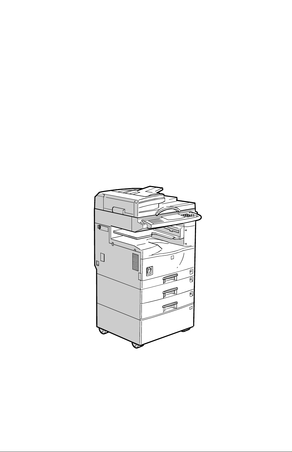
Configuration: Desktop
Copy Process: Dry electrostatic transfer system
Originals: Sheet/Book
Original Size: Maximum A3/11" x 17"
Copy Paper Size: Maximum
A3/11" x 17"
Minimum
A5/8
B6 lengthwise/5
Custom sizes in the by-pass tray:
Width: 90 ~ 305 mm (3.5" ~ 12.0")
Length: 148 ~ 1,260 mm (5.8" ~ 49.6")
Copy Paper Weight: Paper Tray:
60 ~ 90 g/m2, 16 ~ 24 lb
By-pass:
60 ~ 162 g/m2, 16 ~ 43 lb
Reproduction Ratios: 3 Enlargement and 3 Reduction
1/2
" x 5
" sideways (Paper tray)
1/2
1/2
" x 8
" (By-pass)
1/2
Overall
Information
A4/A3 Version LT/DLT Version
200%
Enlargement
Full Size 100% 100%
Reduction
141%
122%
93%
71%
50%
Zoom: 50% to 200% in 1% steps
Power Source: 120 V, 60 Hz:
More than 10 A (for North America)
220 ~ 240 V, 50/60 Hz
More than 6 A (for Europe/Asia)
110 V, 50/60 Hz
More than 11 A (for Taiwan)
155%
129%
121%
93%
78%
65%
1-1
Page 12

SPECIFICATIONS 17 May, 1999
Power Consumption:
Mainframe Only Full System
120 V 220 ~ 240 V 120 V 220 ~ 240 V
Maximum Less than
1.1 kW
Copying Approx.
450 W
Warm-up
Stand-by Approx.
Energy Saver Level 1 Approx. 60 W Approx. 60 W Approx. 60 W Approx. 60 W
Energy Saver Level 2 Approx. 30 W Approx. 30 W Approx. 30 W Approx. 30 W
Auto Shut off 0 W 0 W 0 W 0 W
Approx.
860 W
110 W
Less than
1.1 kW
Approx.
450 W
Approx.
760 W
Approx.
110 W
Less than
1.2 kW
Approx.
460 W
Approx.
870 W
Approx.
130 W
Less than
1.3 kW
Approx.
460 W
Approx.
770 W
Approx.
130 W
NOTE:
1) Full system: Mainframe + ADF + 1-bin Sorter + Paper Tray Unit
2) Without the optional heaters, fax unit, and pri nter contr ol ler
Noise Emission (Sound Power Level):
Stand-by (Mainframe only): US/Asia Model: 42 dB(A)
Europe Model: 30 dB(A)
Operating (Mainframe only): US/Asia Model: 60 dB(A)
Europe Model: 66 dB(A)
Operating (Full System): 66 dB(A)
Off Mode: 30 dB(A)
NOTE:
1) The above measurements were made in accordance with ISO 7779.
2) Full System: Mainframe + ADF + 1-bin Sorter + Paper Tray Unit
Dimensions (W x D x H): 550 x 575 x 460 mm (21.7" x 22.7" x 18.2")
NOTE:
Measurement Conditions
1) With by-pass feed table closed
2) Without the ADF
Weight: Less than 35 kg (78 lb)
Not including ADF, Platen Cover, and AIO
1-2
Page 13

17 May, 1999 SPECIFICATIONS
Copying Speed in Multicopy mode (copies/minute):
A4 sideways/
11" x 8
Non-memory copy mode 15 10 11
Memory copy mode 18 10 12
NOTE:
Measurement Conditions
1/2
"
A3/11" x 17" B4/8
" x 14"
1/2
1) Not APS mode
2) A4/LT copying
3) Full size
Warm-up Time: Less than 30 seconds (20°C, 68°F): 115 V machine
Less than 40 seconds (20°C, 68°F): 230 V machine
First Copy Time: Less than 6.5 seconds
NOTE:
Measurement Conditions
1) When polygonal mirror motor is spinning.
2) Not APS mode
3) A4/LT copying
4) Full size
Copy Number Input: Ten-key pad, 1 to 99 (count up or count down)
Manual Image Density: 7 steps
Overall
Information
Automatic Reset: 60 seconds is the standard setting; it can be changed
with a User Tool.
Automatic Shut Off: 15 minutes is the standard setting; it can be changed
with a User Tool.
Copy Paper Capacity: Paper Tray:
250 sheets
Optional Paper Tray Unit:
500 sheets x 1, or 500 sheets x 2
By-pass Tray:
100 sheets (A4, B5, A5, B6, 8
1/2
10 sheets (A3, B4, 11" x 17", 8
" x 11", 5
" x 13")
1/2
1/2
" x 8
1/2
")
1 sheets (non-standard sizes)
NOTE:
Copy weight: 80g/m2 (20 lb).
Toner Replenishment: All-in-one toner cassette cartridge (750 g/cartridge)
Toner Yield: 12 k copies (A4 sideways, 6% full black, 1 to 1 copying,
ADS mode)
1-3
Page 14

SPECIFICATIONS 17 May, 1999
Optional Equipment:
·
Platen cover
·
Auto document feeder
·
Paper tray unit (1 tray)
·
Paper tray unit (2 trays)
·
1-bin sorter
·
Tray heater
·
Optics anti-condensation heater
·
Drum heater
·
Copier feature expander (48 MB memory)
Copy Capacity: Copy Tray: 250 sheets (without 1-bin sorter),
125 sheets (with 1-bin sorter)
1-bin Sorter: 125 sheets
Memory Capacity:
Standard (16 MB) Optional (+48 MB)
Sort, Rotate Sort
Number of pages
A4, 8
B4, 8
A3, 11" x 17"
A4 ITU-T#4 12% 35 sheets 99 sheets
" x 11"
1/2
1/2
" x 14"
❍❍
❍❍
❍❍
A4 6% 80 sheets 99 sheets
NOTE:
The paper sizes that can be used with Rotate Sort are A4/8
and B5 only.
: Available
❍
" x 11"
1/2
1-4
Page 15
17 May, 1999 MACHINE CONFIGURATION
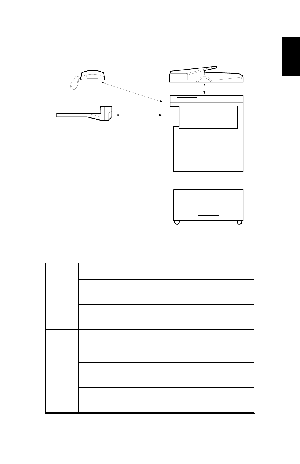
1.2 MACHINE CONFIGURATION
A
B
C
D
Overall
Information
A250V501.WMF
Version Item Machine Code No.
Copier
Fax
Copier A250 D
ADF (Optional) A859 C
Platen Cover (Optional) A893
Paper Tray Unit - 1 tray (Optional) A861
Paper Tray Unit - 2 trays (Optional) A860 E
1-bin Sorter (Optional) A869 B
Memory 48 MB (Optional) A887
Fax Controller (Optional) A891
Telephone (Optional) H160 A
ISDN (Optional) A890
PC Fax Expander (Optional) A894
Fax Function Expander (Optional) A892
Printer Controller (Optional) B305
PS Option (Optional) B308
HDD (Optional) G690
NIB (Optional) B307
Memory 32 or 64 MB (Optional) G688
E
1-5
Page 16
PAPER PATH 17 May, 1999
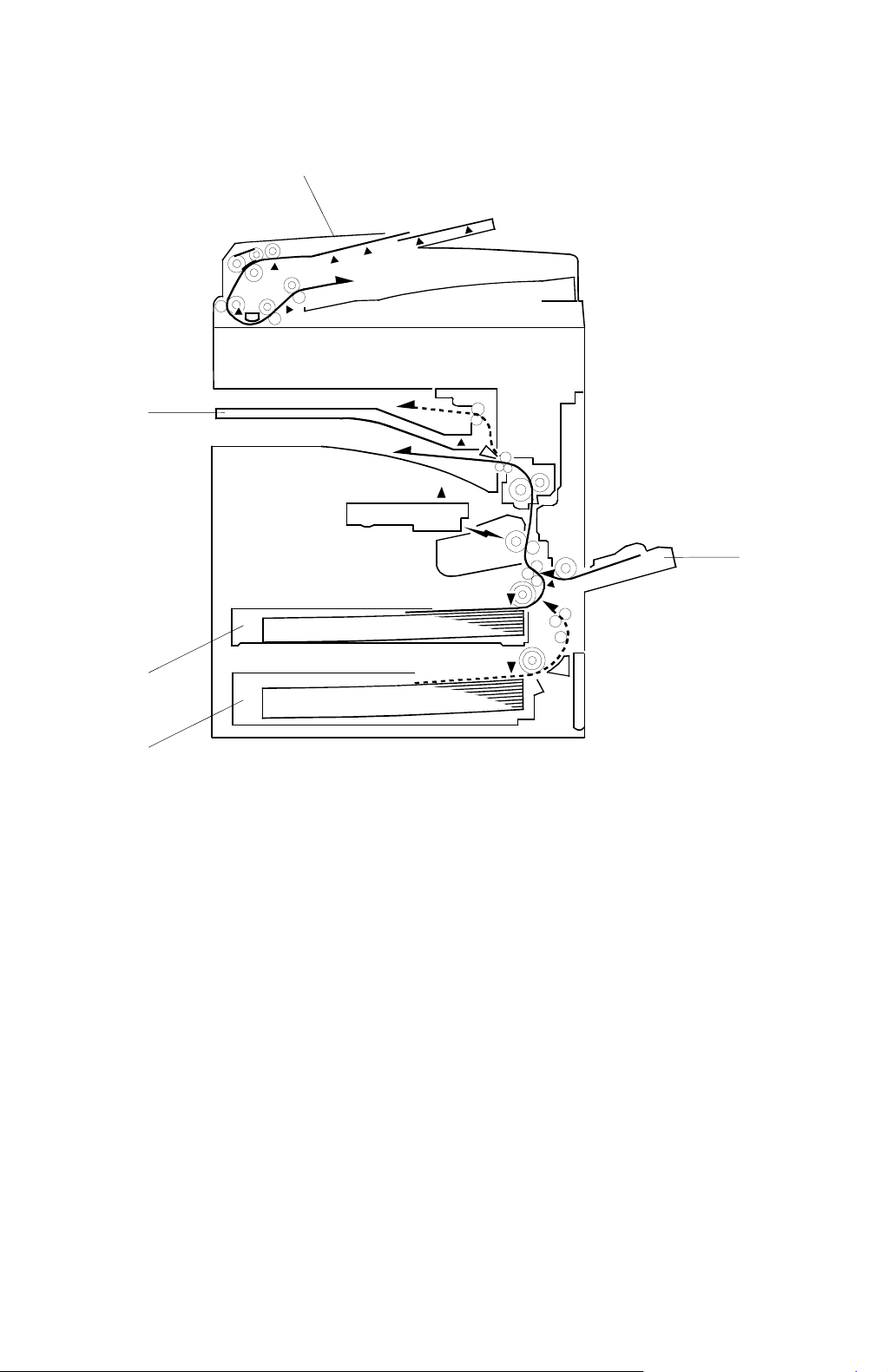
1.3 PAPER PATH
1
5
2
4
3
1. Optional ADF
2. By-pass feed tray
3. Optional paper tray (1 tray)
4. Paper tray
5. Optional 1-bin sorter
A250V000.WMF
1-6
Page 17
17 May, 1999 MECHANICAL COMPONENT LAYOUT
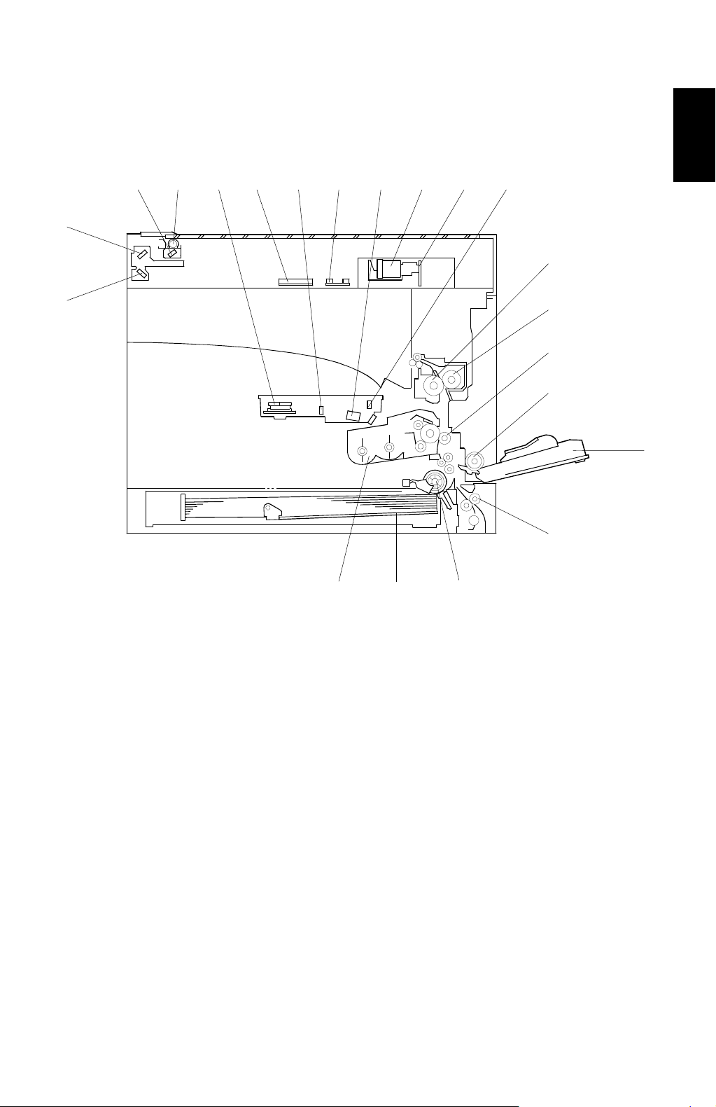
1.4 MECHANICAL COMPONENT LAYOUT
1 2 3 4 5 6 7 8 9 10
21
11
Overall
Information
20
1. 1st mirror (scanner)
2. Exposure lamp
3. Polygonal mirror motor
4. Original width sensor
5. 1st mirror (laser unit)
6. Original length sensor
7. Barrel toroidal lens (BTL)
8. Lens
9. SBU board
10. F-theta mirror
11. Hot roller
12
13
14
15
16
19 18 17
A250V561.WMF
12. Pressure roller
13. Transfer roller
14. By-pass feed roller
15. By-pass table
16. Vertical transport roller
17. Paper feed roller
18. Bottom plate
19. All-in-one cartridge (AIO cartridge)
20. 3rd mirror
21. 2nd mirror
1-7
Page 18

ELECTRICAL COMPONENT DESCRIPTIONS 17 May, 1999
1.5 ELECTRICAL COMPONENT DESCRIPTIONS
Refer to the electrical component layout on the reverse side of the point-to-point
diagram for the location of the components, using the symbols and index numbers.
1.5.1 COPIER ENGINE
Symbol Name Function Index No.
Motors
M1 Scanner Drives the 1st and 2nd scanners. 4
M2 Polygonal Mirror Turns the polygonal mirror. 28
M3 Main Drives the main unit components. 12
M4 Exhaust Fan Removes heat from around the fusing unit. 46
Magnetic Clutches
MC1 Paper Feed Starts paper feed from the tray. 14
MC2 By-pass Feed Starts paper feed from the by-pass table. 15
MC3 Vertical Transport Drives the vertical transport rollers. 18
MC4 Registration Drives the registration rollers. 13
Switches
Main Provides power to the machine. If this is
SW1
SW2 Right Door Switch 1 Cuts the +5 V LD dc power line. 30
Right Door Switch 2
SW3
Vertical Transport
SW4
SW5 Paper Size Detects paper size. 24
Sensors
S1
S2
S3
S4
S5 Toner Near-End Detects toner near-end. 21
S6
S7
Cover Switch
Scanner HP
Original Width Detects original width. This is one of the
Original Length 1 Detects original length. This is one of the
Original Length 2
Paper End Informs the CPU when the tray runs out of
Paper Near-End Informs the CPU when the paper in the
off, there is no power supplied to the
machine.
Detects if the front door is open or not, and
cuts the +24 V dc power line for the main
motor and power pack.
Detects if the front door is open or not, and
cuts the +24 V dc power line for the vertical
transport clutch.
Informs the CPU when the 1st and 2nd
scanners are at home position.
APS (Auto Paper Select) sensors.
APS (Auto Paper Select) sensors.
Detects original length. This is one of the
APS (Auto Paper Select) sensors.
paper.
tray is almost finished. The printer
controller uses this sensor.
40
31
25
3
37
6
6
23
19
1-8
Page 19

17 May, 1999 ELECTRICAL COMPONENT DESCRIPTIONS
Symbol Name Function Index No.
S8
By-pass Tray Paper
Informs the CPU that there is paper in the
by-pass feed table.
16
S9 By-pass Paper Size Detects the paper size in the by-pass tray. 20
S10 Vertical Transport Detects misfeeds. 22
S11
Registration
Detects misfeeds and controls registration
clutch off-on timing.
17
S12 Fusing Exit Detects misfeeds. 35
S13
Exit Tray Paper Detects if there is paper on the exit tray or
not.
27
Platen Cover Informs the CPU that the platen cover is in
S14
the up or down position (related to the
5
APS/ARE functions).
S15 AIO Set Informs the CPU that an AIO is installed. 33
PCBs
PCB1
PCB2
PCB3
PCB4
BICU
PSU Provides dc power to the system and ac
IOB Controls the fusing lamp and the
SBU
Controls all base engine functions both
directly and through other control boards.
power to the fusing lamp and heaters.
mechanical parts of the machine.
Contains the CCD, and outputs a video
signal to the BICU board.
44
39
45
8
PCB5 Lamp Stabilizer Stabilizes the power to the exposure lamp. 7
PCB6 LD Unit Controls the laser diode. 26
PCB7 Operation Panel Controls the operation panel. 36
PCB8 Memory (Option) Expands memory capacity. —
PCB9
PCB10
PCB11
Printer Controller
(Option)
FCU (Option) Controls all fax communications and fax
NCU (Option) Switches the analog line between the fax
Receives print data from a PC.
features, in cooperation with the BICU.
unit and the external telephone.
42
43
47
Overall
Information
Lamps
L1
Exposure Lamp Applies hig h int ensity light t o the original
for exposure.
L2 Fusing Lamp Heats the hot roller. 10
Heaters
H1
Anti-condensation
(Option)
Turns on when the main switch is off to
prevent moisture from forming on the
optics.
Drum (Option) Turns on when the main switch is off to
H2
prevent moisture from forming around the
drum.
1-9
2
1
—
Page 20

ELECTRICAL COMPONENT DESCRIPTIONS 17 May, 1999
Symbol Name Function Index No.
Others
TF1
Fusing Thermofuse
Opens the fusing lamp circuit if the fusing
unit overheats.
9
TH1 Fusing Thermistor Detects the temperature of the hot roller. 11
PP1
LSD 1
CO1
CO2
C/B/T Power Pack
Laser Synchronization
Detector
Total Counter Keeps track of the total number of prints
Key Counter (Option)
Provides high voltage for the charge,
development and transfer rollers.
Detects the laser beam at the start of the
main scan.
made.
Used for control of authorized use. If this
feature is enabled for coping, coping will be
38
29
48
—
impossible until it is installed.
LED1 Exit Tray Indicates if there is paper on the exit tray. 32
LED2
1-bin Sorter Indicates if there is paper on the 1-bin
sorter. 1-bin sorter is option.
34
SP1 Speaker T urns on during fax communication. 41
1-10
Page 21
17 May, 1999 DRIVE LAYOUT
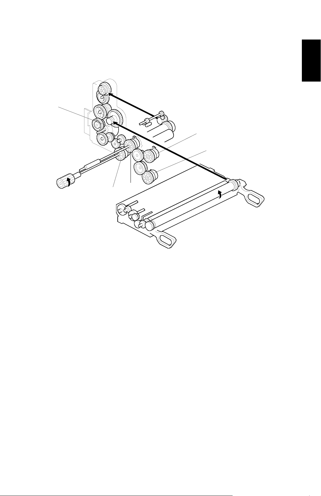
1.6 DRIVE LAYOUT
5
1
2
3
4
Overall
Information
1. By-pass feed clutch
2. Vertical transport clutch
3. Registration clutch
4. Paper feed clutch
5. Main motor
A250V109.WMF
1-11
Page 22
COPY PROCESS 17 May, 1999
1.7 COPY PROCESS
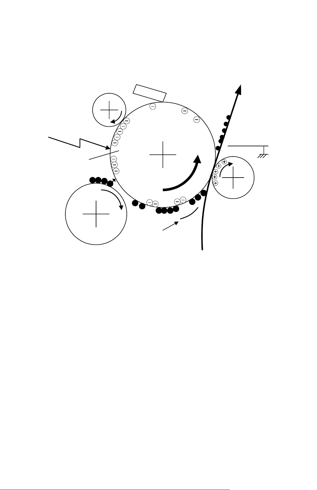
1.7.1 OVERVIEW
6
1
OPC
–600 V
5
2
–100 V
4
3
–400 V
A250V507.WMF
1. DRUM CHARGE
In the dark, the charge roller gives a negative charge of –600 volts to the
organic photo-conductive (OPC) drum. The charge remains on the surface of
the drum because the OPC layer has a high electrical resistance in the dark.
2. LASER EXPOSURE
The processed data scanned from the original is retrieved from the memory
and transferred to the drum by a laser beam, which forms an electrical latent
image on the drum surface. The amount of charge remaining as a latent image
on the drum depends on the laser beam intensity to about –100 volts, which is
controlled by the BICU board.
3. DEVELOPMENT
The development roller charges the toner with a negative bias of –400 volts.
Toner particles jump across to the drum and electrostatically attach to the
areas of the drum surface where the laser reduced the negative charge on the
drum.
1-12
Page 23

17 May, 1999 COPY PROCESS
4. IMAGE TRANSFER
Paper is fed to the area between the drum surface and the transfer roller at the
proper time for aligning the copy paper and the developed image on the drum
surface. Then, the transfer roller applies a high positive charge to the reverse
side of the paper. This positive charge pulls the toner particles from the drum
surface onto the paper. At the same time, the paper is electrostatically attracted
to the transfer roller.
5. PAPER SEPARATION
Paper separates from the drum as a result of the electrostatic attraction
between the paper and the transfer roller. The discharge plate helps separate
the paper from the drum.
6. CLEANING
The cleaning blade removes any toner remaining on the drum surface after the
image transfers to the paper.
7. QUENCHING
There is no quenching lamp. The power supply board applies 1.6 kVp-p (1.05
mA) 1 kHz AC to the charge roller. This current removes any remaining voltage
on the drum surface.
Overall
Information
1-13
Page 24
BOARD STRUCTURE 17 May, 1999
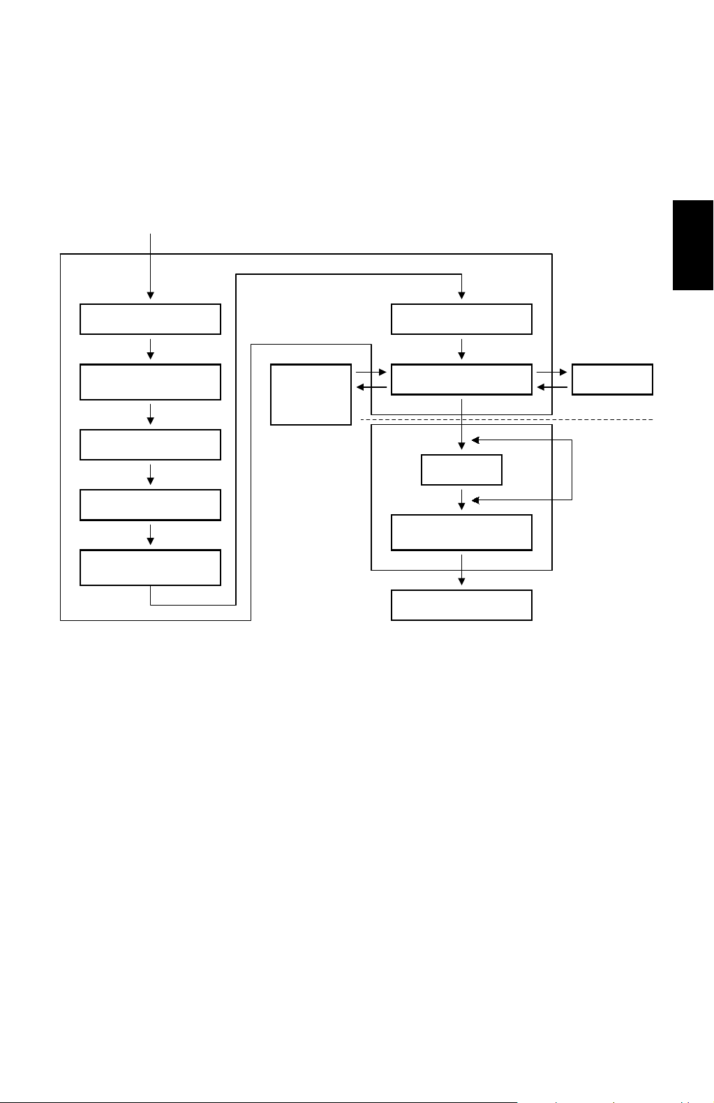
1.8 BOARD STRUCTURE
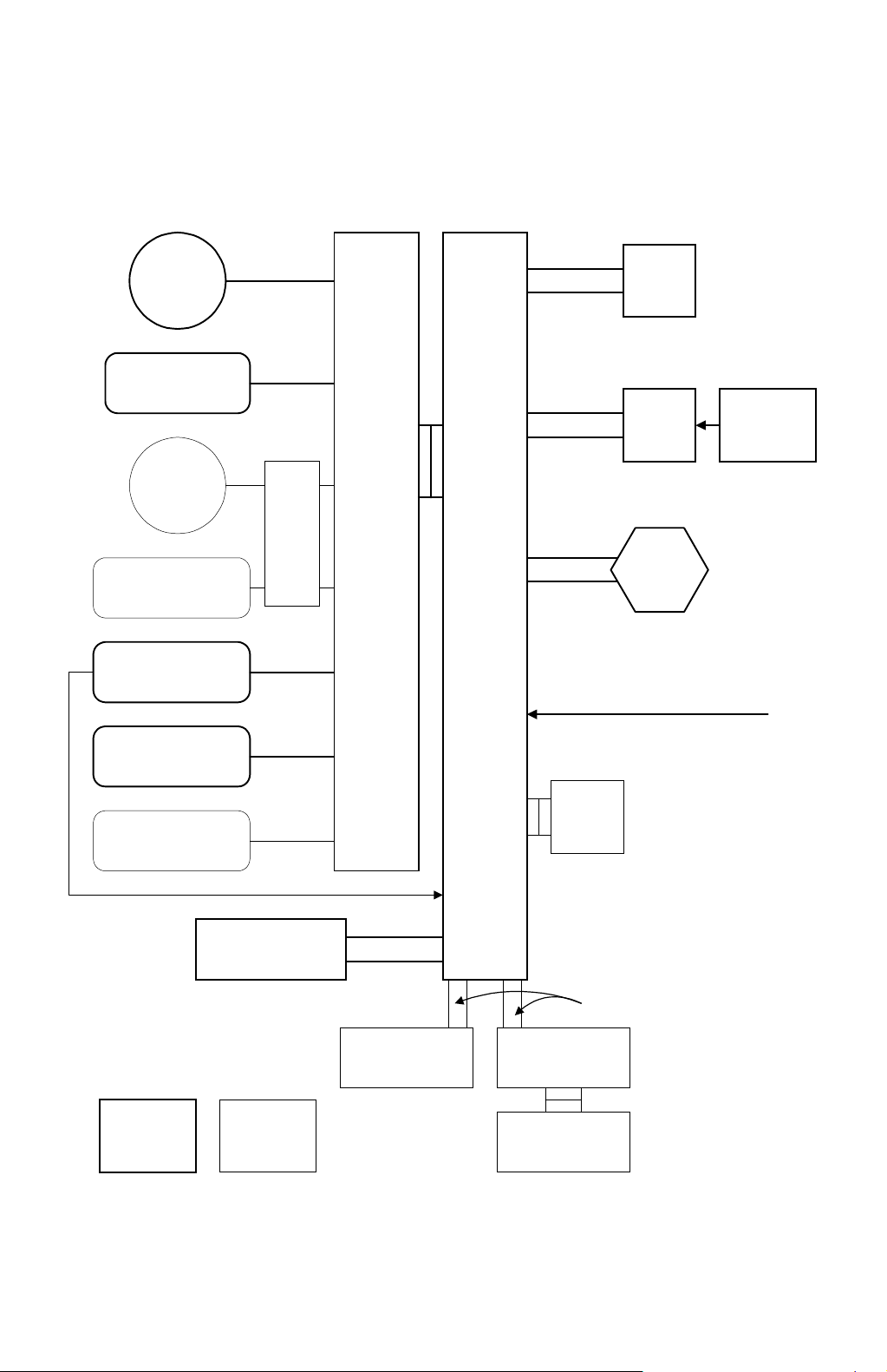
1.8.1 OVERVIEW
Scanner
Motor
Scanner Sensors
DF
Motor
DF Sensors,
Solenoids
Laser Printer
Sensors, Solenoids,
Motors, Clutches
PSU
DF
Drive
PCB
IOB
BICU
Flat Cable
Harness
Harness
Laser Synchronization
Signal = Fibre Optic Cable
SBU
LDD
Circuit
Board
Polygon
Mirror
Motor
Photo
Diode
Peripheral Sensors,
Motors, Solenoids,
Clutches
Operation Panel
Standard Option
EMB
Harness
Flat Cable
Fax Controller Mother Board
Printer Controller
A250V504.WMF
1-14
Page 25

17 May, 1999 BOARD STRUCTURE
1.8.2 DESCRIPTION
1. BICU (Base Engine and Image Control Unit)
The main board controls the following functions:
·
Engine sequence
·
Scanner, laser printer engine
·
Timing control for peripherals
·
Image processing, video control
·
Operation control
·
Various application boards (fax, printer)
·
Machine control, system control
2. IOB (I/O Board)
The IOB handles the following functions:
·
Drive control for the sensors, motors, and solenoids of the printer and
scanner
·
High voltage control board control
·
Serial interfaces with peripherals
·
Fusing control
3. SBU (Sensor Board Unit)
Overall
Information
The SBU deals with the analog signals from the CCD and converts them into digital
signals.
4. EMB (Extended Memory Board) (Option)
The EMB stores the image data. An extra 48 MB of memory can be added. This
increases the number of pages that can be stored.
1-15
Page 26
17 May, 1999 SCANNING
2. DETAILED SECTION DESCRIPTIONS
2.1 SCANNING
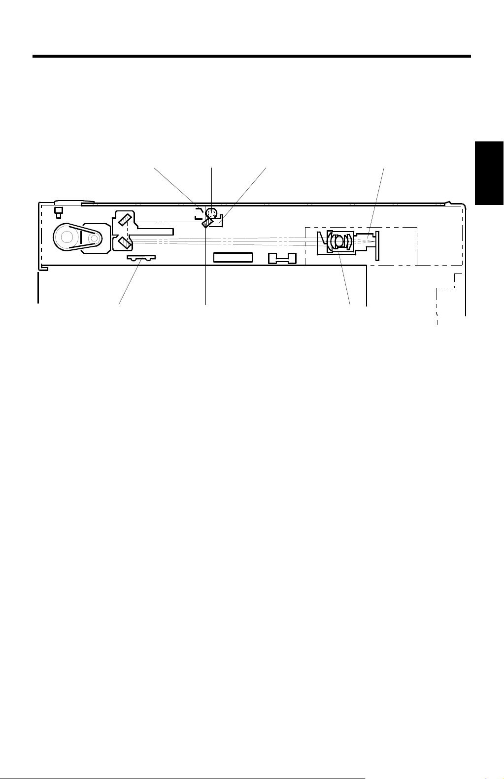
2.1.1 OVERVIEW
[E] [A] [D] [C]
[G] [F] [B]
Detailed
Descriptions
A250D003.WMF
An exposure lamp [A], a xenon lamp in this model, illuminates the original. The 1st,
2nd, 3rd mirrors, and lens [B] reflect the image onto the CCD (charge coupled
device) [C]. The SBU (Sensor Board Unit) consists of the CCD and the lens.
The 1st scanner [D] consists of the exposure lamp, a reflector [E], and the 1st
mirror [F].
The exposure lamp is energized by a DC supply to avoid uneven light intensity as
the 1st scanner moves in the sub-scan direction. The entire exposure lamp surface
is frosted to ensure even exposure in the main scan direction.
The light reflected by the reflector is of almost equal intensity to the light from the
exposure lamp, to reduce shadows on pasted originals.
An optics anti-condensation heater [G] is available as an option. It can be installed
on the left side of the scanner unit. It turns on whenever the power cord is plugged
in and the machine is in off condition.
2-1
Page 27

SCANNING 17 May, 1999
2.1.2 SCANNER DRIVE
[A]
[E]
[D]
[C]
[B]
[D]
A250D001.WMF
The scanner drive motor [A] (a stepper motor) drives the 1st and 2nd scanners [B,
C] through the timing belts [D], scanner drive pulley [E], and the Accuride rail at the
rear.
Book Mode
The main CPU controls and operates the scanner drive motor. In full size mode,
the 1st scanner speed is 92 mm/s during scanning. The 2nd scanner speed is half
that of the 1st scanner.
In reduction or enlargement mode, the scanning speed depends on the
magnification ratio (M: 0.5 to 2.00). The returning speed is always the same,
whether in full size or magnification mode.
Changing the scanner drive motor speed changes the magnification in the subscan direction. Use SP mode (SP4-101) to adjust this.
In the main scan direction, magnification is done by image processing on the BICU
(Base Engine Image Control Unit) board. Adjust magnification in the main scan
direction with SP4-008.
ADF Mode
The scanners remain in their home position (the scanner H.P sensor detects the
1st scanner) to scan the original. The ADF motor feeds the original through the
ADF.
In reduction/enlargement mode, changing the ADF motor speed adjusts the image
length in the sub-scan direction (adjust with SP6-007). The BICU board adjusts the
magnification in the main scan direction, in the same way as in book mode (adjust
with SP4-008).
2-2
Page 28

17 May, 1999 SCANNING
2.1.3 ORIGINAL SIZE DETECTION IN PLATEN MODE
[B]
[B]
[A]
A250D526.WMF
[A]
[C]
A250D002.WMF
In the optics cavity, there are four reflective sensors in the 115 V machines, and six
reflective sensors in the 230 V machines. These are the original width sensors [A]
and the original length sensors [B], and they detect the length and width of the
original. They are also known as the APS (Auto Paper Selection) sensors.
Detailed
Descriptions
While the main switch is on, these sensors are active and the original size data is
always sent to the CPU. However, the CPU checks the data only when the platen
cover is opened.
The main CPU takes the original size data when the platen cover sensor [C]
activates. This is when the platen is about 15 cm above the exposure glass. At this
time, only the sensor(s) located underneath the original receive the reflected light
and switch on. The other sensor(s) remain off. The main CPU can recognize the
original size from the on/off signals from the APS sensors.
If the copy is made with the platen fully open, the main CPU decides the original
size from the sensor outputs when the Start key is pressed.
2-3
Page 29

SCANNING 17 May, 1999
Original Size Length Sensors Width Sensors
A4/A3 ver sion LT/DLT version L1 L2 L3 L4 S1 S2
A3 11" x 17"
B4 10" x 14"
F4 8
A4-L 8
B5-L —
A4-S 11" x 8
B5-S —
1/2
" x 14" (8" x 13")
1/2
" x 11"
1/2
"
mmmmmm
mmmmm7
mmm7 77
mm7777
m77777
7777mm
7777m7
m
: ON 7: OFF
NOTE:
The length sensors L1 and L2 are used only for 230 V machines.
For other combinations, the operation panel will display “CANNOT DETECT ORIG.
SIZE”.
The above table shows the sensor output for each original size. This original size
detection method eliminates the necessity for pre-scanning and increases the
machine's productivity.
However, if the by-pass feed table is used, note that the machine assumes that the
copy paper is lengthwise. For example, if A4 sideways paper is placed on the bypass tray, the machine assumes it is A3 paper and scans a full A3 area,
disregarding the original size sensors. However, for each page, the data signal to
the laser diode is stopped to match the copy paper length detected by the
registration sensor. This means that copy time for the first page may be slower
(because of the longer time required for scanning), but it will be normal for the rest
of the job.
2-4
Page 30
17 May, 1999 IMAGE PROCESSING
g
g
g
2.2 IMAGE PROCESSING
2.2.1 OVERVIEW
Circuit
Data from SBU
IPU
Detailed
Descriptions
Auto Shadin
Scanner Gamma
Correction
Magnification
Filterin
ID Gamma
Correction
Application
(Fax or
Printer Unit)
Gradation Processin
Video Data Control
FCI
Printer Gamma
Correction
LD Controller
EMB
LD Unit
VCU
A250D500.WMF
The CCD generates an analog video signal. The SBU (Sensor Board Unit)
converts the analog signal to an 8-bit digital signal, then it sends the digital signal
to the BICU (Base-engine and Image Control Unit) board.
The BICU board is divided into two image processing blocks; the IPU (Image
Processing Unit), and memory.
·
IPU: Auto shading, filtering, magnification, gamma (g) correction, and
gradation processing
Finally, the BICU board sends the video data to the LD unit at the correct time.
LD unit is divided into two blocks, VCU (Video Control Unit) and LD controller.
·
VCU:
FCI (Fine Character Image) – Smoothing, Printer gamma (g)
correction
·
LD controller:
LD print timing control
2-5
Page 31

IMAGE PROCESSING 17 May, 1999
Image Quality Adjustments
The user can select text, text/photo, and photo mode, as usual. However, each of
these original modes have a range of different types, as follows.
Image adjustment (08) in the user tools
Mode Default
Text
Text/Photo
Photo
Toner Saving
—
Coarse
The user can select the mode that best suits their original with the following user
tool: User Tools - General Features - 08. Image Adjustment.
Notice that there is a “Service Mode” for each of the text, text/photo, and photo
original modes. This is a customizable mode, with a range of SP modes that can
be adjusted to meet user requirements that are not covered by the other original
modes.
For details of the SP modes that can be used to adjust the image quality for all the
original modes, see the Image Processing Summary section.
Normal Sharp (Service Mode)
Photo Priority Text Priority (Service Mode)
Press Print Glossy Print (Service Mode)
2-6
Page 32

17 May, 1999 IMAGE PROCESSING
2.2.2 SBU (SENSOR BOARD UNIT)
Amp.
ODD
CCD
EVEN
Z/C
Z/C
AGC
Reference
Controller
Analog
Processing IC
Z/C: Zero Clamp
AGC: Automatic Gain Control Circuit
SBU
A/D
Vin
ref
GA-S600
BICU
Detailed
Descriptions
IPU
A250D502.WMF
The CCD converts the light reflected f rom the original into an analog signal. The
CCD line has 7,450 pixels and the resolu tion is 600 dpi (23.6 dots/mm).
The CCD has two output lines, for odd and even pixels, to the analog processing
IC. The analog processing IC does the following to the signals from the CCD:
1. Z/C (Zero Clamp):
Adjusts the black level reference for even pixels to match the odd pixels.
2. Signal Composition:
A switching device merges the analog signals for the odd and even pixels from
the CCD.
3. Signal Amplification:
Operational amplifiers in the AGC circuit amplify the analog signal. The CPU on
the BICU board controls the maximum gains of the operational amplifiers.
After the processing mentioned above, the A/D converter converts the analog
signals to 8-bit signals. This gives a value to each pixel on a scale of 256 grades.
Then, the digitized image data goes to the BICU board.
2-7
Page 33

IMAGE PROCESSING 17 May, 1999
2.2.3 AUTO IMAGE DENSITY (ADS)
[A]
A250D004.WMF
In the SBU
ADS prevents the background of an original from appearing on copies.
The copier scans the image density area [A] detected by the ADS sensoras shown
in the diagram. This corresponds to a few mm at one end of the main scan line. As
the scanner scans down the page, the IPU on the BICU detects the peak white
level for each scan line. The IPU determines the reference value for the A/D
conversion for a particular scan line using the peak white level for that scan line.
Then, the IPU sends the reference value to the reference controller circuit on the
SBU.
When scanning an original with a gray background, the density of the gray area is
the peak white level density. Therefore, the original background will not appear on
copies. ADS corrects for any changes in background density down the page,
because peak level data is taken for each scan line.
As with previous digital copiers, the user can select manual image density when
selecting auto image density mode and the machine will use both settings when
processing the original.
In the IPU
After the SBU process, the IPU board removes more background by adjusting the
white level.
If the user selects a “Service Mode” original type with the user tools, these two
ADS process can be either enabled or disabled (SP4-936, SP4-937), and the
amount of white level change can be adjusted (SP4-938).
2-8
Page 34

17 May, 1999 IMAGE PROCESSING
2.2.4 IMAGE PROCESSING UNIT (IPU)
Overview
The image data from the SBU goes to the Image Processing Unit (IPU) IC on the
BICU board, which carries out the following processes with the image data:
·
Auto shading
·
Scanner gamma (g) correction
·
Magnification
·
Filtering (MTF and smoothing)
·
ID gamma (g) correction
·
Binary picture processing
·
Error diffusion
·
Dithering
·
Video path control
·
Test pattern generation
The image data then goes to either the LD controller or the FCI depending on the
selected copy modes.
Detailed
Descriptions
Auto Shading
A250D517.WMF
As with previous digital copiers, there are two auto shading methods. One is black
level correction and the other is white level correction. Auto shading corrects errors
in the signal level for each pixel.
Black Level Correction
The CPU reads the black dummy data from one end of the CCD signal (32 pixels
at the end are blacked off) and takes the average of the black dummy data. Then,
the CPU deletes the black level value from each image pixel.
2-9
Page 35

IMAGE PROCESSING 17 May, 1999
White Level Correction
Before scanning the original, the machine reads a reference waveform from the
white plate. The average of the white video level for each pixel is stored as the
white shading data in the FIFO memory in the IPU chip.
The video signal information for each pixel obtained during image scanning is
corrected by the IPU chip.
Auto shading for the first original is done before the scanning.
After scanning every page, auto shading is done to prepare for the next page.
If the copy image density or the original mode is changed during copy run, the auto
shading for the next scan is done before the scanning to respond to the mode
changed.
White Line Erase Compensation
During the white level correction, if extremely low CCD output is detected in some
parts of the line, the machine assumes this is due to abnormal black lines on the
white plate. This low output is corrected using neighboring pixels. To switch off this
correction, use SP4-918 (for the original modes known as “Service Mode”) and
SP4-942 (other original modes).
Black Line Erase Compensation
In ADF mode, if extremely low CCD output is detected on the scanning line before
the leading edge of original arrives there, this is attributed to abnormal black dots
on the exposure glass. This low output is corrected using neighboring pixels. To
adjust or switch off this correction, use SP4-919 (for the original modes known as
“Service Mode”) and SP4-943 (other original modes).
2-10
Page 36

17 May, 1999 IMAGE PROCESSING
Scanner Gamma (g) Correction
The CCD output is not proportional to the quantity of the light received. Scanner
gamma (g) correction corrects the CCD output so that grayscale data is proportion
to the quantity of the light received.
The machine has four possible scanner gamma curves. The curve used by the
machine depends on the original type selected by the user (at the operation panel
and with 08. Image Adjustment in the user tools). If the user selects one of the
original modes known as “Service Mode”, the gamma curve can be selected with
SP4-928.
If “0” is selected with SP 4-928, the scanner gamma curve is either AE or NAE,
depending on the selected original mode (text, photo, etc.).
The four gamma (g) correction curves and their characteristics are as follows:
·
Non Auto Exposure ID linear (NAE): Corrects the image data in proportion to the
original density.
·
Auto Exposure ID linear (AE): Removes the background from the image data to
some extent and corrects the rest of the image data in proportion to the original
density.
·
Reflection Ratio ID Linear (Linear): Uses the image data without correction.
·
Removed background (SP): Removes the background area completely and
corrects the rest of the image data in proportion to the original density.
Detailed
Descriptions
Output
Removed Background
Reflection Ratio ID Linear
NAE
AE
SP
Original Density
A250D550.WMF
2-11
Page 37

IMAGE PROCESSING 17 May, 1999
Main Scan Magnification/Reduction
Main Scan Magnification/Reduction
Changing the scanner speed enables reduction and enlargement in the sub-scan
direction. However, the IPU chip handles reduction and enlargement in the main
scan direction. The processing for main scan magnification/reduction is the same
as in the previous digital machines.
[A]
A250D504.WMF
When makin g a copy using the ADF, the magnific ation circuit creates a mirror
image. This is because the scanning starting position in the main scan direction is
at the other end of the scan line in ADF mode (compared with platen mode). In
platen mode, the original is placed face down on the exposure glass, and the
corner at [A] is at the start of the main scan. The scanner moves down the page. In
ADF mode, the ADF feeds the leading edge of the original to the DF exposure
glass, and the opposite top corner of the original is at the main scan start position.
To create the mirror image, the CPU stores each line a LIFO (Last In First Out)
memory.
2-12
Page 38

17 May, 1999 IMAGE PROCESSING
Filtering
Image adjustment (08) in the user tools
Mode Default
Text
Text/Photo
Photo
Toner Saving
—
Coarse
Normal Sharp (Service Mode)
Photo Priority Text Priority (Service Mode)
Press Print Glossy Print (Service Mode)
Overview
There are some software filters for enhancing the desired image qualities of the
selected original mode. These fil ters ar e the M TF filter , the smoot hing fil ter , and
independent dot erase.
The MTF filter emphasizes sharpness and is used in Text and Text/Photo modes.
The smoothing filter is used in Photo mode, except for Glossy Photo mode (Glossy
Photo mode is one of the photo modes that can be selected with User Tools General Features - 08. Image Adjustment). In Glossy Photo mode, the MTF filter is
used.
Detailed
Descriptions
Independent dot erase removes unwanted dots from the image.
MTF Filter Adjustment - Text and Text/Photo Modes
When the user selects “Service Mode” for either Text or Text/Photo original type
(User Tools - General Features - 08. Image Adjustment), the MTF filter and
coefficient can be adjusted with SP4-915 and 4-916.
It is difficult to simply explain the relationships between the filter coefficient and
filter strengths. Refer to the following charts to determine how to make the filters
weaker or stronger. A large black dot indicates the default setting.
When the filter is stronger in the main scan direction, lines parallel to the feed
direction are emphasized. When the filter is stronger in the sub-scan direction, lines
at right angles to the feed direction are emphasized. A stronger MTF filter can
make a low ID image visible but moiré may become more visible. Moiré is reduced
using a smoothing filter specially designed for this purpose (see “Smoothing Filter
Adjustment - Text/Photo”).
2-13
Page 39

IMAGE PROCESSING 17 May, 1999
StrongLevel
4
4
5
•
3
3
5
•
5
5
1
2
4
•
0 1 3 1 3 1 3 3 4 1 3 15 3 1 1 15 4 15 3 3 3 15 3 3
1 2 3 4 5 6 7 8 9 10 11 12 13 14 15 16 17 18 19 20 21 22 23 24
0 2 3 2 3 2 2 3 4 2 2 11 3 1 2 11 4 13 2 8 3 13 2 3
0 2 2 3 3 4 4 4 4 5 5 2 5 0 0 3 5 3 0 0 0 3 0 0
Week
SP
Main Scan: Filter Confficient
1. Text in Service Mode
0 2 2 3 3 4 4 4 4 5 5 3 5 6 0 3 5 3 0 5 0 4 6 6
4-915-001
Sub-scan: Filter Confficient
Main Scan: Filter Strength
Sub-scan: Filter Strength
Main • Confficient:
Text in Service Mode
(50% ~ 95%)
4
4-915-005
4-916-001
4-916-005
Sub • Confficient:
Main • Strength:
Sub • Strength:
1
255
•
4-915-002
4-915-006
4-916-002
4-916-006
Main • Confficient:
Sub • Confficient:
Main • Strength:
Sub • Strength:
(96% ~ 125%)
(126% ~ 159%)
4-915-003
4-915-007
4-916-003
4-916-007
4-915-004
4-915-008
Main • Confficient:
Sub • Confficient:
Main • Strength:
Sub • Strength:
Main • Confficient:
Sub • Confficient:
(160% ~ 200%)
4-916-004
4-916-008
Main • Strength:
Sub • Strength:
2-14
A250D601.WMF
Page 40

17 May, 1999 IMAGE PROCESSING
StrongLevel
Detailed
Descriptions
3
3
3
3
•
0 1 3 1 3 1 3 3 4 1 3 15 3 1 1 15 4 15 3 3 3 15 3 3
1 2 3 4 5 6 7 8 9 10 11 12 13 14 15 16 17 18 19 20 21 22 23 24
0 2 3 2 3 2 2 3 4 2 2 11 3 1 2 11 4 13 2 8 3 13 2 3
0 2 2 3 3 4 4 4 4 5 5 2 5 0 0 3 5 3 0 0 0 3 0 0
Week
SP
Main Scan: Filter Confficient
2. Text/Phot in Service Mode
0 2 2 3 3 4 4 4 4 5 5 3 5 6 0 3 5 3 0 5 0 4 6 6
4-915-009
4-915-014
4-916-009
Main • Confficient:
Sub • Confficient:
Sub-scan: Filter Confficient
Main Scan: Filter Strength
Sub-scan: Filter Strength
Text in Service Mode
(50% ~ 89%)
Main • Strength:
333
•
4-915-010
4-916-014
Sub • Strength:
4-915-015
Main • Confficient:
Sub • Confficient:
(90% ~ 95%)
1
2
•
3
4-916-010
4-916-015
Main • Strength:
Sub • Strength:
(96% ~ 125%)
5
4-915-011
4-915-016
4-916-011
Main • Confficient:
Sub • Confficient:
Main • Strength:
5
1
2
5
•
4-916-016
4-915-012
Sub • Strength:
Main • Confficient:
(126% ~ 159%)
5
4-915-017
4-916-012
4-916-017
Sub • Confficient:
Main • Strength:
Sub • Strength:
125
•
4-915-013
Main • Confficient:
(160% ~ 200%)
5
4-915-018
4-916-013
4-916-018
Sub • Confficient:
Main • Strength:
Sub • Strength:
2-15
A250D602.WMF
Page 41

IMAGE PROCESSING 17 May, 1999
Smoothing Filter Adjustment - Photo Mode
Image adjustment (08) in the user tools
Mode Default
Text
Text/Photo
Photo
Toner Saving
—
Coarse
Normal Sharp (Service Mode)
Photo Priority Text Priority (Service Mode)
Press Print Glossy Print (Service Mode)
When the user selects “Service Mode” for Photo original type (User Tools - General
Features - 08. Image Adjustment), the smoothing filter can be changed with SP4-
927. A stronger smoothing filter makes the image more blurred (1: Weak ~ 8:
Strong).
Smoothing Filter Adjustment - Text and Text/Photo Modes
To reduce the possibility of moiré, a small-matrix smoothing filter is used after
scanner gamma (g) correction in the Text and Text/Photo mode. The level of
smoothing can be adjusted with SP4-921 (0: Weak, 1: Normal, 2: Strong, 3:
Disabled).
This is only used when the user selects “Service Mode” for either Text or
Text/Photo original type (User Tools - General Features - 08. Image Adjustment).
Independent Dot Erase
In Text mode and in Text/Photo mode, independent dots are detected using a 7 x 9
matrix and erased from the image.
The independent dot detection level can be adjusted with SP4-917 (for the original
modes known as “Service Mode”) and SP4-944 (other original modes – on/off only;
no adjustment). With a larger SP setting, more dots are detected as independent
dots and erased, even if the dot's density is high. However, dots in mesh-like
images may be detected as independent dots mistakenly.
Independent Dot Erase after Binary Picture Processing
Image adjustment (08) in the user tools
Mode Default
Text
Text/Photo
Photo
Toner Saving
—
Coarse
Normal Sharp (Service Mode)
Photo Priority Text Priority (Service Mode)
Press Print Glossy Print (Service Mode)
Normally, independent dot erase is done in the filtering stage. However, when the
user selects “Service Mode” for Text original type (User Tools - General Features -
08. Image Adjustment), independent dots may reappear in the image after the
binary picture processing. These independent dots are erased after gradation
processing.
SP4-939 changes the filter that is used for this process, and it can be also used to
disable this feature. A smaller matrix is more likely to remove dots.
2-16
Page 42

17 May, 1999 IMAGE PROCESSING
ID Gamma (g) Correction
ID Gamma (g) Correction
Image adjustment (08) in the user tools
Mode Default
Text
Text/Photo
Photo
Toner Saving
—
Coarse
Normal Sharp (Service Mode)
Photo Priority Text Priority (Service Mode)
Press Print Glossy Print (Service Mode)
The machine automatically selects the most appropriate ID gamma correction
based on the selected original type (and the user tool Image Adjustment setting)
and ID setting made at the operation panel .
When the user selects “Service Mode” for any original type (User Tools - General
Features - 08. Image Adjustment), you can use SP4-940 to change ID correction in
service mode. The types that can be selected with SP4-940 are different for each
original mode (Text, Text/Photo, or Photo).
Detailed
Descriptions
Gradation Processing
Image adjustment (08) in the user tools
Mode Default
Text
Text/Photo
Photo
Toner Saving
—
Coarse
Normal Sharp (Service Mode)
Photo Priority Text Priority (Service Mode)
Press Print Glossy Print (Service Mode)
Overview
The 8-bit image data is converted into 1-bit data (there is no 8-bit greyscale
processing, only the 1-bit process known as binary picture processing).
However, different techniques are used, depending on the selected original type
(text, text/photo, photo) and user tool Image Adjustment setting.
These techniques are simple binary picture processing, error diffusion, and
dithering. To see which process is used, see the flow charts in the Image
Processing Summary section.
·
Simple binary picture processing: Each video signal pixel is converted from 8-bit
to 1-bit (black and white image data) in accordance with a threshold value.
·
Error diffusion: Error diffusion is a more complex process using a threshold value
and the values of nearby pixels in an 8 x 8 matrix. In text/photo mode, e
rror
diffusion reduces the difference in contrast between light and dark areas of a
halftone image. In text mode, it prevents
parts of low contrast text from
disappearing from the copy.
·
Dithering:
Each pixel is compared with a pixel in a dither matrix.
2-17
Page 43

IMAGE PROCESSING 17 May, 1999
In error diffusion or simple binary picture processing, there are two possible types
of threshold: constant threshold, and dynamic threshold.
·
The type that is used depends on the selected original type (text, text/photo,
photo) and user tool Image Adjustment setting.
·
However, if the user selects “Service Mode” for either Text or Text/Photo original
type (User Tools - General Features - 08. Image Adjustment), the thresholding
type can be changed with SP4-922.
Dithering is only used in Photo mode (except for Glossy Photo, in which error
diffusion is used).
Constant Threshold Value
If the constant threshold method is used, the threshold remains the same all the
time.
The threshold can be adjusted with SP 4-923 when the user selects “Service
Mode” for the Text original type (User Tools - General Features - 08. Image
Adjustment).
Decreasing the threshold value creates a darker image.
Dynamic Threshold Value
Overview
Dynamic thresholding is designed to clearly separate text/vector graphic objects
from the background.
When used with simple binary picture processing (Sharp Text mode)
The software compares each pixel with the pixels immediately surrounding it. It is
tested in four directions: horizontal, vertical, and in the two diagonal directions. If
the image density difference between the object pixel and the surrounding pixels is
more than a certain value in any one of these directions, the pixel is determined to
be on an edge.
Pixels on the edge are treated with dynamic thresholding. The threshold is
calculated by averaging the densities of pixels in the surrounding 7 x 7 area.
However, the calculated threshold cannot exceed maximum and minimum limits; if
it does, the upper or lower limit is used.
Pixels that are not on an edge are treated with a constant threshold value.
As a side-effect of the dynamic threshold process, copies of originals where the
rear side is visible through the paper or the background is dark, may tend to have
dirty background. In this case it is necessary to adjust the image density level with
the image density key on the operation panel.
Instead of sharp text mode, if the user selects “Service Mode” for Text original type
(User Tools - General Features - 08. Image Adjustment), some adjustments can be
made.
2-18
Page 44

17 May, 1999 IMAGE PROCESSING
·
Edge detection: SP4-931 (vertical direction), 4-932 (horizontal direction), 4-933
(diagonal from top right to bottom left), 4-934 (diagonal from top left to bottom
right). Decreasing the SP mode value causes a lighter line to be detected as an
edge.
·
Threshold limits for edges, and the threshold for non-edge pixels: SP4-924
(Max), 4-925 (Min), and 4-926 (Center, used for non-edge pixels). The closer that
the upper or lower limit is adjusted to the center threshold, the fewer stains
appear. However, a low ID cont rast image cannot be copied.
When used with error diffusion (Normal Text)
After error diffusion processing, dynamic thresholding uses 64 threshold values in
an 8 x 8 matrix. This process prevents low contrast text from disappearing.
If the user selects “Service Mode” for Text/Photo original type and the thresholding
type is changed from constant to dynamic, an error diffusion filter can be selected
with SP4-929-1 (No.1: 4 x 4 matrix and No.2: 8 x 8 matrix). The two selections are
prepared for future use to match original types which are not supported currently.
Therefore, at this moment SP4-929-1 should not be used.
Dithering
If the user selects “Service Mode” for Text/Photo original type, the dither matrix can
be selected with SP4-929-2. A larger value for this SP mode increases the number
of gradations. However, the image will not have much contrast.
Detailed
Descriptions
2-19
Page 45

IMAGE PROCESSING 17 May, 1999
2.2.5 MEMORY CONTROLLER AND EXTENDED MEMORY BOARD (EMB)
Optional
IPU
Memory
Controller
DRAM
(48 MB)
CPU
BUS
DRAM
BICU
The BICU consists of the memory controller and the DRAM. The functions of each
device are as follows.
Memory Controller: Compressing the 1-bit image data
Image rotation
Image data transfer to the DRAM
DRAM (standard 16MB): Stores the compressed data
Working area
(16 MB)
A250D528.WMF
The data goes to the memory controller after binary picture processing. The data is
first compressed and then stored in the DRAM. When printing, the data from the
DRAM goes back to the memory controller, where it is decompressed and image
editing is done (e.g., image rotation, repeat image).
The memory capacity changes after installing optional memory on the BICU board,
as follows.
16 MB + Optional
(64 MB total)
Number of pages
Standard (16 MB)
A4 6% 80 99
ITU-T#4 (12% black) 35 99
2-20
Page 46

17 May, 1999 IMAGE PROCESSING
g
g
2.2.6 VIDEO CONTROL UNIT (VCU)
Fine Character and Image (FCI)
The FCI performs image smoothing and line width correction. These functions only
affect binary picture processed images in sharp text mode.
Smoothing
Fig. A
Fi
. B
Fi
. C
Sub Scan
Direction
Main Scan Direction
4/4 3/4 2/4 1/4 0
Detailed
Descriptions
A250D554.WMF
Usually, binary picture processing generates jagged edges on characters, as
shown in the above illustration. These are reduced using edge smoothing. The FCI
changes the laser pulse duration and position for certain pixels.
Fig. A shows the four possible pulse durations, and Fig. B shows how the laser
pulse can be in one of three positions within the pixel. Fig. C shows an example of
how edge smoothing is used.
SP2-902 switches FCI smoothing on or off.
2-21
Page 47

IMAGE PROCESSING 17 May, 1999
Toner Saving in Text Mode
Image adjustment (08) in the user tools
Mode Default
Text
Text/Photo
Photo
Toner Saving
—
Coarse
Normal Sharp (Service Mode)
Photo Priority Text Priority (Service Mode)
Press Print Glossy Print (Service Mode)
When toner saving in text mode is selected in the image adjustment sub-menu (08)
of the user tools menu, an 8 x 8 matrix filter reduces the number of black dots in
the image. As a result, less toner is used to create the latent image on the drum.
Printer Gamma (g) Correction
Printer correction corrects the data output from the IPU to the laser diode to
account for the characteristics of the printer (e.g., the characteristics of the drum,
laser diode, and lenses).
The machine chooses the most suitable gamma curve for the original type selected
by the user. There is no SP adjustment for this.
2-22
Page 48

17 May, 1999 IMAGE PROCESSING
g
g
g
y
g
g
2.2.7 IMAGE PROCESSING SUMMARY
Text (Normal)
This mode decreases moiré and prevents parts of low contrast text from
disappearing from the copy.
Recommended Originals: Normal text originals
Scannin
Image
Correction
Ma
nification
Filterin
Image Processing Flow Related SP Modes
ADS
• Auto Shadin
• White/Black Line Erase
Correction
• Scanner Gamma
Correction (ADS)
• Small Smoothin
Main Scan Magnification
MTF (Medium)
Independent Dot Erase
Filter
• SP4-942, 4-943
• SP4-008
• SP4-944
Detailed
Descriptions
ID Control
Gradation
Printer
Gamma
Correction
ID Gamma Correction
(Normal Text)
Error Diffusion Process
namic Threshold)
(D
Printer Gamma Correction
(Text)
A250D605.WMF
The “Toner Saving” setting uses the above processes, and also uses the toner
saving matrix.
2-23
Page 49

IMAGE PROCESSING 17 May, 1999
g
g
g
g
g
g
g
Text (Sharp)
This mode prevents the rear side of a thin original from being visible, and the copy
will have a lot of contrast.
Recommended Originals: Newspaper, originals through which the rear side is
visible.
Image Processing Flow Related SP Modes
ADS
Scannin
Image
Correction
nification
Ma
Filterin
ID Control
Gradation
• Auto Shadin
• White/Black Line Erase
Correction
• Scanner Gamma
Correction (ADS)
• Small Smoothin
Main Scan Magnification
MTF (Strong)
Independent Dot Erase
ID Gamma Correction
(Sharp Text)
Simple Binary Picture
Processin
(Dynamic Threshold)
Filter
• SP4-942, 4-943
• SP4-008
• SP4-944
• SP2-902
A250D606.WMF
Printer
Gamma
Correction,
and Others
FCI Smoothin
Line Width Correction
Printer Gamma Correction
(Text)
2-24
Page 50

17 May, 1999 IMAGE PROCESSING
g
g
g
g
g
g
Text (Service Mode)
For special text originals that need custom settings to produce the required copy
quality.
Scannin
Image
Correction
nification
Ma
Filterin
Image Processing Flow Related SP Modes
ADS
• Auto Shadin
• White/Black Line Erase
Correction
• Scanner Gamma
Correction (Linear)
• Small Smoothin
Main Scan Magnification
MTF (Strong)
Independent Dot Erase
Filter
• SP4-936-1
• SP4-937-1
• SP4-938-1
• SP4-918-1, 4-919-1
• SP4-928-1
• SP4-921-1
• SP4-008
• SP4-915-1 ~ 8
• SP4-916-1 ~ 8
• SP4-917-1
Detailed
Descriptions
ID Control
Gradation
Printer
Gamma
Correction
and Others
ID Gamma Correction
(Sharp Text)
Simple Binary Picture
Processin
(Dynamic Threshold)
Independent Dot Erase
Line Width Correction
Printer Gamma Correction
(Text)
2-25
• SP4-940-1
• SP4-922-1
• SP4-923
• SP4-924, 4-925, 4-926
• SP4-931 to 934
• SP4-939
• SP4-935-1
A250D607.WMF
Page 51

IMAGE PROCESSING 17 May, 1999
g
g
g
y
g
g
Text/Photo (Photo Priority)
This mode emphasizes gr adati on and pictur e repr od ucti o n.
Recommended Originals: Text/photo originals which contain mainly photo areas.
Image Processing Flow Related SP Modes
ADS
Scannin
Image
Correction
Ma
nification
Filterin
ID Control
Gradation
• Auto Shadin
• White/Black Line Erase
Correction
• Scanner Gamma
Correction (ADS)
• Small Smoothin
Main Scan Magnification
MTF (Weak)
Independent Dot Erase
ID Gamma Correction
(Photo Priorit
Error Diffusion
(Constant Threshold)
Filter
)
• SP4-942, 4-943
• SP4-008
• SP4-944
Printer
Gamma
Correction
Printer Gamma Correction
(Text/Photo)
A250D608.WMF
2-26
Page 52

17 May, 1999 IMAGE PROCESSING
g
g
g
y
g
g
Text/Photo (Text Priority)
This mode maintains gradation and prevents characters in text from being
deformed.
Recommended Originals: Text/photo originals which contain mainly text areas.
Scannin
Image
Correction
Ma
nification
Filterin
Image Processing Flow Related SP Modes
ADS
• Auto Shadin
• White/Black Line Erase
Correction
• Scanner Gamma
Correction (ADS)
• Small Smoothin
Main Scan Magnification
MTF (Medum)
Independent Dot Erase
Filter
• SP4-942, 4-943
• SP4-008
• SP4-944
Detailed
Descriptions
ID Control
Gradation
Printer
Gamma
Correction
ID Gamma Correction
(Text Priorit
Error Diffusion
(Constant Threshold)
Printer Gamma Correction
(Text)
)
2-27
A250D609.WMF
Page 53

IMAGE PROCESSING 17 May, 1999
g
g
g
g
y
g
g
y
Text/Photo (Service Mode)
For special text/photo originals that need custom settings to produce the required
copy quality.
Image Processing Flow Related SP Modes
Scannin
Image
Correction
nification
Ma
Filterin
ADS
• Auto Shadin
• White/Black Line Erase
Correction
• Scanner Gamma
Correction (ADS or NonADS b
the ima
• Small Smoothin
Main Scan Magnification
Independent Dot Erase
key selection of
e density mode)
Filter
MTF (Medium)
• SP4-936-2
• SP4-937-2
• SP4-938-2
• SP4-918-2
• SP4-919-2
• SP4-928-2
• SP4-921-2
• SP4-008
• SP4-915-9 ~ 18
• SP4-916-9 ~ 18
• SP4-917-2
ID Control
Gradation
Printer
Gamma
Correction
and Others
ID Gamma Correction
(Text Priorit
Error Diffusion
(Constant Threshold)
Line Width Correction
Printer Gamma Correction
(Text)
)
• SP4-940-2
• SP4-922-2
• SP4-929-1
• SP4-935-2
A250D610.WMF
2-28
Page 54

17 May, 1999 IMAGE PROCESSING
g
g
g
g
g
g
Photo (Coarse Print)
This mode emphasizes contrast of photo images, and results in coarse gradation.
Recommended Originals: Large-image printed originals, with no text.
Scannin
Image
Correction
nification
Ma
Filterin
ID Control
Gradation
Image Processing Flow Related SP Modes
• Auto Shadin
• White/Black Line Erase
Correction
• Scanner Gamma
Correction (Non-ADS)
• Small Smoothin
Main Scan Magnification
Smoothing Filter
ID Gamma Correction
(Coarse Print)
Ditherin
(Matrix 53 Lines)
Filter
• SP4-942, 4-943
• SP4-008
Detailed
Descriptions
Printer
Gamma
Correction
Printer Gamma Correction
(Photo)
A250D611.WMF
2-29
Page 55

IMAGE PROCESSING 17 May, 1999
g
g
g
g
g
Photo (Press Print)
This mode emphasizes contrast of photo images, and results in medium gradation
Recommended Originals: Fine-image printed originals, with no text.
Image Processing Flow Related SP Modes
• Auto Shadin
Scannin
Image
Correction
• White/Black Line Erase
Correction
• Scanner Gamma
Correction (Non-ADS)
• SP4-942, 4-943
nification
Ma
Filterin
ID Control
Gradation
Printer
Gamma
Correction
Main Scan Magnification
Smoothing Filter
ID Gamma Correction
(Press Print)
Ditherin
(Matrix 105 Lines)
Printer Gamma Correction
(Photo)
• SP4-008
A250D612.WMF
2-30
Page 56

17 May, 1999 IMAGE PROCESSING
g
g
g
y
g
Photo (Glossy Photo)
This mode maintains the resolution of the original and reprod uces the fi ne
gradations.
Recommended Original: Glossy photos
Scannin
Image
Correction
nification
Ma
Filterin
ID Control
Gradation
Image Processing Flow Related SP Modes
• Auto Shadin
• White/Black Line Erase
Correction
• Scanner Gamma
Correction (Non-ADS)
Main Scan Magnification
MTF (Weakest)
ID Gamma Correction
(Gloss
Error Diffusion Process
(Constant Threshold)
Photo)
• SP4-942, 4-943
• SP4-008
Detailed
Descriptions
Printer
Gamma
Correction
Printer Gamma Correction
(Photo)
A250D613.WMF
2-31
Page 57

IMAGE PROCESSING 17 May, 1999
g
g
g
g
g
y
g
Photo (Service Mode)
For special photo originals that need custom settings to produce the required copy
quality.
Image Processing Flow Related SP Modes
Scannin
Image
Correction
nification
Ma
Filterin
ID Control
ADS
• Auto Shadin
• White/Black Line Erase
Correction
• Scanner Gamma
Correction (ADS or NonADS b
the ima
Main Scan Magnification
ID Gamma Correction
key selection of
e density mode)
Smoothing Filter
(Coarse Print)
• SP4-936-3
• SP4-937-3
• SP4-938-3
• SP4-918-3, 4-919-3
• SP4-928-3
• SP4-008
• SP4-927-1 ~ 5
• SP4-940-3
Gradation
Printer
Gamma
Correction,
and Others
Ditherin
(Matrix 105 Lines)
Line Width Correction
Printer Gamma Correction
(Photo)
• SP4-929-2
• SP4-935-3
A250D614.WMF
2-32
Page 58

17 May, 1999 LASER EXPOSURE
2.3 LASER EXPOSURE
2.3.1 OVERVIEW
[A]
[C]
Detailed
Descriptions
[B]
A250D000.WMF
This machine uses a laser diode to produce electrostatic images on the OPC drum
[A] in the all-in-one cartridge [B]. The laser diode unit [C] converts image data from
the BICU board into laser pulses, and the optical components direct these pulses
to the drum.
Laser beam exposure on the drum creates the latent image. The laser beam
makes the main scan while drum rotation controls the sub-scan.
Strength of the beam output 5 mW
Strength of the beam on the drum 0.636 mW
Printing Binary
Polygon mirror motor speed:
Resolution (dpi) Motor Speed (rpm) Data Frequency (MHz)
600 22478.22 22.0926
2-33
Page 59

LASER EXPOSURE 17 May, 1999
2.3.2 OPTICAL PATH
[H]
[G]
[A]
[F]
[I]
[B]
[E]
[C]
[J]
[D]
A250D306.WMF
[A]: Polygonal mirror
[B]: Cylindrical lens
[C]: LD drive board
[D]: Drum
[G]: BTL (Barrel Toroidal Lens)
[H]: 1st mirror
[I]: Laser synchronization detector
[J]: Toner shield glass
[E]: LD shutter
[F]: F-theta mirror
The optical path from the laser diode to the drum is shown above.
The LD drive board [C] outputs the laser beam to the polygonal mirror [A] through
the cylindrical lens [B], which focus the laser beam.
The laser beam goes to the F-theta mirror [F], 1st mirror [H] and BTL [G]. Then, the
beam reaches the drum [D] through the toner shield glass [J].
The beam reflected by the polygonal mirror writes the pixels of the latent image on
the drum. The F-theta mirror [F] ensures constant intervals between the pixels. The
BTL [G] corrects for irregularities in the polygonal mirror faces.
The laser synchronization detector [I] synchronizes the start of the main scan.
2-34
Page 60

17 May, 1999 LASER EXPOSURE
2.3.3 AUTO POWER CONTROL (APC)
LD Drive Board
5V
LD PD
A250D308.WMF
LEVEL
VIDEO
LD MODE
LD OFF
VCC
LD Driver
Detailed
Descriptions
To prevent the intensity of the laser beam from changing because of the
temperature, the machine monitors the laser beam with a photodiode (PD). The PD
is enclosed in the laser diode. The PD passes an electrical current to the LD driver
IC and this IC adjusts its output level to keep the laser diode output constant.
The laser diode power level is adjusted on the production line.
CAUTION:
Do not touch the variable resistors on the LD unit in the field.
2-35
Page 61

LASER EXPOSURE 17 May, 1999
2.3.4 LD SAFETY SWITCH
IOB LD Drive Board
+5V
Right Door
Switch 1
BICU Board
LD Driver
LD
PD
A250D555.WMF
Right Door Switch 1
To ensure that the laser beam does not inadvertently switch on during servicing,
there is a safety switch inside the right door. The switch is in series on the LD 5 V
line coming from the IOB through the BICU board.
Mechanical Laser Shutter
When the all-in-one cartridge is removed, the laser shutter is released and this
interrupts the laser beam.
2-36
Page 62

17 May, 1999 ALL-IN-ONE CARTRIDGE (AIO CARTRIDGE)
2.4 ALL-IN-ONE CARTRIDGE (AIO CARTRIDGE)
2.4.1 OVERVIEW
[A]
[B]
[C]
[D]
[E]
[H][I]
[G] [F]
Detailed
Descriptions
A250D509.WMF
The AIO cartridge (all-in-one cartridge) consists of the components shown above. It
contains the OPC drum and the toner cassette, and includes the mechanisms for
drum charge, development, and cleaning. The drum is 30 mm in diameter.
[A]: Charge roller
[B]: Cleaning blade
[C]: OPC drum
[D]: Transfer roller
[F]: Development roller
[G]: Mixing blade
[H]: Toner near-end sensor
[I]: Agitator
[E]: Transfer blade
The main motor drives the rollers in the AIO cartridge. The charge roller [A]
charges the drum [C]. Monocomponent toner is used. The cleaning blade [B]
cleans the drum surface.
To remove any remaining voltage on the drum surface, the laser diode periodically
discharges the OPC drum. The interval can be changed with SP2-901. The default
setting is every 25 pages; the machine will wait until the current job is finished.
2-37
Page 63

ALL-IN-ONE CARTRIDGE (AIO CARTRIDGE) 17 May, 1999
2.4.2 DRIVE
[C]
[A]
[D]
[B]
A250D510.WMF
The main motor [A] drives the drum [B], the development roller [C], and agitators
[D] through a series of gears. The BICU controls the main motor speed.
2-38
Page 64

17 May, 1999 ALL-IN-ONE CARTRIDGE (AIO CARTRIDGE)
2.4.3 DRUM CHARGE
[A]
[D]
[B]
[C]
[E]
A250D511.WMF
This machine uses a drum charge roller instead of a scorotron corona wire to
charge the drum. The drum charge roller [A] is always in contact with the surface of
the drum [B] because of the charge roller pressure springs [C], and it gives a
negative charge to the drum surface. While the drum is rotating, the drum charge
roller also turns because of friction between the roller and the drum.
The drum charge roller system generates less ozone than a scorotron corona wire
charge. Consequently, this machine does not have an ozone filter.
Detailed
Descriptions
The power supply board supplies a negative DC voltage to the drum charge roller
through the charge roller terminal [D], pressure spring [C], and bushing [E]. This
gives the drum surface a negative charge (–600 V).
The power supply board also applies AC voltage (1.6 kVp-p 1 kHz) to the charge
roller. This AC removes any remaining voltage on the drum.
The AIO cartridge does not have a cleaning pad, temperature control, or a contact
mechanism for the drum charge roller. The material the drum charge roller is made
of enables the AIO cartridge to be a simple mechanism. The drum charge roller is
part of the AIO cartridge, so when the toner runs out, the drum charge roller is
changed at the same time. This happens before the drum charge roller gets dirty.
2-39
Page 65

ALL-IN-ONE CARTRIDGE (AIO CARTRIDGE) 17 May, 1999
2.4.4 DEVELOPMENT
Overview
[A]
[D]
[E]
[F]
[G]
[B] [C]
A250D509.WMF
This machine uses monocompo nent toner. There are two agitators [A] in the AIO
cartridge (shown above).
The agitator(s) [A] and the mixing blade [B] mix the toner in the AIO cartridge and
transport it to the development roller [C]. Friction between the transported toner
and the doctor blade [D] gives the toner a negative charge.
Internal permanent magnets in the development roller attract the toner to the
development roller sleeve. The doctor blade trims the toner to the desired
thickness on the development roller sleeve. The development roller does not
contact the drum [E]. There is a small gap between the toner on the surface of the
development roller sleeve and the drum. Toner jumps across this gap to develop
the latent image.
The development bias consists of AC and DC components. The AC component
improves the transfer of toner.
The transfer blade [F] is charged to the same voltage as the development bias.
This helps to keep the toner on the drum.
The toner near-end sensor [G] is located under the toner cartridge.
2-40
Page 66

17 May, 1999 ALL-IN-ONE CARTRIDGE (AIO CARTRIDGE)
Toner End Detection
High
Low
Toner near end Sensor Output
[A] [B] [C]
Detailed
Descriptions
5 s
[D] [E]
[F]
A250D666.WMF
There is no toner end sensor in this machine. Instead, toner end is detected using
the toner near-end sensor.
When the toner near-end sensor detects a low toner condition for five seconds
continuously [A], the machine starts the toner near-end copy counter.
From this point, toner near-end/end detection depends on the settings of SP2-213
and 2-214. The following descri bes what hap pens with the default settings.
If the toner concentration is still low after 210 copies, the machine detects a toner
near-end condition [B]. The number of copies between starting the counter and
toner near end [D] can be changed with SP2-214.
If the toner concentration is still too low 150 copies after toner near-end was
determined, the machine detects a toner end condition [C]. If toner end is detected,
the machine stops and copying/printing is disabled. The number of copies between
toner near-end and toner end [E] can be changed with SP2-213.
The total number of copies between starting the copy counter and toner end [F]
depends on the SP2-214 and SP2-213 settings. The default is 150 + 210 = 360
copies.
2-41
Page 67

ALL-IN-ONE CARTRIDGE (AIO CARTRIDGE) 17 May, 1999
The following table shows how the two SP modes can be used to customize the
toner near-end and end interv al s.
SP2-213 setting
(near-end to end)
0: 150 sheets
1: 50 sheets
2: 250 sheets
0: Normal 1: Low 2: High
®
Start
Near-end
near-end: 210
®
end: 150
Total: 360
®
Start
Near-end
near-end: 310
®
end: 50
Total: 360
®
Start
Near-end
near-end: 110
®
end: 250
Total: 360
SP2-214 setting
(count start to near-end)
Start
®
near-end: 350
®
Near-end
end: 150
Total: 500
®
Start
Near-end
near-end: 450
®
end: 50
Total: 500
®
Start
Near-end
near-end: 250
®
end: 250
Total: 500
Start
®
near-end: 0
Near-end
®
Start
near-end: 70
Near-end
®
Start
near-end: 0
Near-end
®
end: 150
Total: 150
®
end: 50
Total: 120
®
end: 250
Total: 250
Notes on how to customize the settings
·
A higher 'Total' means that the user can use the cartridge for longer. However,
copy quality may deteriorate before the toner end warning occurs.
·
With a smaller number of copies between starting the counter and near-end, the
user has an earlier warning that the toner is running out.
When the toner near-end sensor has detected a high toner condition for five
continuous seconds, the machine does not check for toner end/near-end condition
just after the main switch is turned on, or after the right door is opened and closed.
The near-end copy count continues.
If the sensor detects a high toner condition for more than 30 seconds, the machine
stops the near-end copy count. The counter is then reset and the near-end or end
condition is changed.
Toner Supply
The AIO cartridge agitators and mixing blade mix the toner in the AIO cartridge.
The toner near-end sensor is not used to control toner supply. When the machine
is turned on or the right door is closed, the agitators and the mixing blade rotate to
mix the toner for a brief period.
Development Bias
The high voltage supply unit gives the development roller a charge of –400 V DC
and an AC component of 1.6 kVp-p 1 kHz. To prevent toner from transferring to
non-image areas on the drum, the development bias is different for image and nonimage areas.
2-42
Page 68

17 May, 1999 ALL-IN-ONE CARTRIDGE (AIO CARTRIDGE)
2.4.5 DRUM CLEANING
[D]
[A]
[B]
[C]
Detailed
Descriptions
A250D512.WMF
The cleaning blade [A] removes any toner remaining on the drum after the image is
transferred to the paper. The cleaning blade scrapes off the remaining toner on the
drum automatically transferring it to the collection area. The mylar sheet [B]
prevents the toner from dropping out of the cleaning unit.
The toner cartridge in the AIO cartridge has a toner collection coil [C] and scraper
[D]. These improve the collection of waste toner.
There is no toner recycling mechanism.
2-43
Page 69

IMAGE TRANSFER AND PAPER SEPARATION 17 May, 1999
2.5 IMAGE TRANSFER AND PAPER SEP ARATION
2.5.1 OVERVIEW
[C]
[A]
[B]
A250D513.WMF
The machine uses a transfer roller [A], which touches the surface of the drum [B].
The Power Pack - B/C/T supplies a positive current to the transfer roller, which
attracts the toner from the drum onto the paper. The current depends on the paper
width, paper type, and paper feed tray.
Drive from the drum through a gear turns the transfer roller. The antistatic brush [C]
helps the paper to separate from the drum. The antistatic brush is grounded.
Use SP2-301 to adjust the transfer current. Note that when adjusting SP2-301-2
(by-pass tray), the transfer currents for both normal and thick paper are changed
(but not the setting for “Special” paper - adjust that with SP2-301-5).
2-44
Page 70

17 May, 1999 IMAGE TRANSFER AND PAPER SEPARATION
2.5.2 TRANSFER CURRENT SETTINGS
NOTE:
A3/11” x 17”,
A4/8
B4
A4/11” x 8
A5/5
A5/8
A6 sideways
‘Special’ paper in the SP modes appears as “Dry” paper in the user tools.
Paper Tray By-pass Feed
Paper Size
x 11”sideways
1/2
lengthwise,
1/2
x 8
x 5
1/2
1/2
sidewise
lengthwise,
1/2
1/2
Normal
Paper
11 mA 25 mA 12 mA5
11 mA 25 mA 13 mA5
11 mA 25 mA 14 mA7
11 mA 25 mA 17 mA 17 mA 25 mA
Special
Paper
Normal
Paper
Thick
Paper
m
A 25 mA
m
A 25 mA
m
A 25 mA
Special
Paper
Be careful when increasing the transfer current. This might cause a ghosting effect,
in which part of the image at the top of the page is repeated lower down the page
at a lower density. It may also damage the OPC drum in the worst case.
Notes on the 'Normal', 'Thick' , and 'Special' paper settings
The by-pass tray allows a wider range of paper thickness, and the 'Normal' setting
covers paper that is thicker than allowed in the standard tray
At normal temperatures, thicker paper needs a higher current for sufficient toner
transfer.
Detailed
Descriptions
However, at low and high temperatures, image problems occur. A lower current
has been found to solve these problems (use the 'Thick' setting).
·
Low temperatures: Blurred image
·
High temperatures: Insufficient toner transfer
To summarize:
·
Normal: Normal paper; also for thick paper at normal temperatures
·
Thick: Thick paper at low and high temperatures, if those image problems occur
Note that the fusing temperature increases if the 'Thick' setting is used.
Special paper
The 'Special' paper setting is for use when a high transfer current is needed, to
solve certain copy quality problems. It is not normally a good idea to use a high
current, for the reason stated earlier, just below the table.
2-45
Page 71

IMAGE TRANSFER AND PAPER SEPARATION 17 May, 1999
2.5.3 TRANSFER ROLLER CLEANING
If the paper size is smaller than the image, or if a paper jam occurs during printing,
toner may be transferred to the roller surface. To prevent the toner from
transferring to the back side of the printouts, the transfer roller requires cleaning
before the next printing run.
During transfer roller cleaning, the high voltage supply unit supplies a negative
cleaning voltage to the transfer roller. Any negatively charged toner on the transfer
roller is then transferred back to the drum. Then a positive cleaning voltage is
applied to the transfer roller to push back to the drum any positively charged toner
on the transfer roller.
The machine goes through the cleaning mode in the following conditions:
·
After a paper jam ha s been cleared .
·
Just after the power is switched on.
·
After 10 or more sheets of paper have been copied and the copy job has
finished.
SP 2-910 determines how often the transfer roller is cleaned. If this is set to 1, the
transfer roller is cleaned after every job. If it is set to 0, the roller is cleaned every
10 copies (the machine waits until the end of the job).
2-46
Page 72

17 May, 1999 PAPER FEED
2.6 PAPER FEED
2.6.1 OVERVIEW
[D]
[A]
[B]
[C]
Detailed
Descriptions
[E]
A250D201.WMF
There is a built-in paper tray (tray 1) [A] and a by-pass tray [B].
The paper tray holds 250 sheets. The by-pass tray can hold 100 sheets of paper.
The paper feed roller [C] drives the top sheet of paper from the paper tray to the
registration rollers [D].
The paper tray has a friction pad [E] that allows only one sheet to feed at a time.
When the paper tray is closed after the paper is loaded, the paper size actuator
(behind the paper size indicator located at the front right of the tray) pushes the
tray paper size switch. This informs the CPU that the tray is in place and what
paper size is in the tray.
2-47
Page 73

PAPER FEED 17 May, 1999
2.6.2 BUILT-IN TRAY
Bottom Plate Lift
[A]
[D]
[E]
[B]
[C]
A250D104.WMF
The tray bottom plate [A] is lifted by a compressed spring, and it lifts the paper to
the paper feed roller.
When the cassette is be in g pulled out, the tray bottom plate is dropped by the
cassette arm [B], which is connected to the cassette lever (handle) [C], and is
locked by the stopper [D].
When the ca ssette is put in the machine, the stopper is released and the tray
bottom plate moves up.
Paper End Detection
When the paper tray runs out of paper, the actuator for the paper end sensor [E]
drops into the cutout in the tray bottom plate, activating the paper end sensor.
The paper near end sensor is on the machine frame above the back right corner of
the cassette tray. The sensor is only used in printer mode.
2-48
Page 74

17 May, 1999 PAPER FEED
Paper Feed Drive
[E]
[F]
[A]
[B]
[C]
[D]
Detailed
Descriptions
A250D518.WMF
The main motor drives the pick-up an d feed mechanism. The tray paper feed clutc h
[A] transfers drive from the main motor to the paper feed roller [B].
This machine uses a feed roller and friction pad mechanism. The friction pad [C]
only allows the top sheet to feed. Therefore, during paper feed, the top sheet of
paper is separated from the stack and fed to the registration rollers [D].
When the paper actuates the registration sensor [E], the tray paper feed clutch
turns off. When the paper reaches a certain position, the registration clutch [F]
turns on to transfer drive from the main motor to the registration rollers. Then the
registration rollers feed the paper to the image transfer area.
2-49
Page 75

PAPER FEED 17 May, 1999
Paper Size Detection
[A]
[B]
A250D108.WMF
The paper size switch [A] includes three sensors (microswitches). Actuators on a
dial [B] behind the paper size indicator plate actuate the sensors.
Each paper size has its own actuator, with a unique combination of notches. To
determine the paper size, the CPU reads which switches the actuator has turned
off.
The CPU disables paper feed from a tray if the paper size cannot be detected. If
the paper size actuator is broken, or if there is no tray installed, the printer control
board recognizes that the paper tray is not installed.
When the paper size actuator is at the “Q” mark, the paper tray can be set up to
accommodate one of a wider range of paper sizes by using a user tool at the
machine’s operation panel.
Models Switch Location
North America Europe Left Center Right
8
" x 14" O A5 P
1/2
A4 P A4 P
8
" x 11" O A4 O
1/2
QQ
8
" x 13" O 8
1/2
8
" x 11" P 8
1/2
" x 13" O
1/2
" x 11" P
1/2
11" x 17" O A3 O
OFF OFF ON
ON OFF OFF
ON ON OFF
OFF ON ON
ON ON OFF
ON OFF ON
ON ON ON
2-50
ON: Pushed OFF: Not Pushed
Page 76

17 May, 1999 PAPER FEED
2.6.3 BY-PASS TRAY
Drive
[A]
[B]
[E]
[C]
Detailed
Descriptions
[D]
A250D999.WMF
When paper is placed on the tray, the by-pass tray paper feeler [A] is pushed up
and the actuator leaves the by-pass tray paper sensor [B].
The by-pass tray paper feed clutch [C] transfers drive from the main motor to the
by-pass feed roller [D].
This machine uses a feed roller and friction pad mechanism, with drive from the
main motor transmitted when the by-pass feed clutch turns on. The friction pad
only allows the top sheet to feed to the registration rollers.
When the paper leading edge activates the registration sensor, the re gistration
clutch [E] turns on.
2-51
Page 77

PAPER FEED 17 May, 1999
Paper Size Detection
[A]
A250D107.WMF
The by-pass feed paper width sensor monitors the paper width. The side fence is
connected to the terminal plate gear. When the side fences move to match the
paper width, the circular terminal plate rotates over the wiring patterns on the
rectangular part of the width sensor. The patterns for each paper width on the
paper width detection sensor are unique.
North America
CN No. (IOB) DLT LG 8" x 13" HLTR
CN 321-1 H H L L
CN 321-2 H H H H
CN 321-3 (GND) L L L L
CN 321-4 L H H H
CN 321-5 L or H L L H
Europe
CN No. (IOB) A3 B4 A4R 8" x 13" A5R
CN 321-1 H H H L L
CN 321-2 H H H H H
CN 321-3 (GND) L L L L L
CN 321-4 L L H H H
CN 321-5 H L L L H
2-52
Page 78

17 May, 1999 PAPER FEED
2.6.4 PAPER REGISTRATION
[B]
[A]
[D]
[C]
Detailed
Descriptions
A250D518.WMF
Main motor rotation is transmitted to the registration clutch gear [A].
The registration sensor [B] is just before the registration rollers [C].
When the paper leading edge activates the registration sensor, the re gistration
clutch [D] turns on and the registration rollers start turning a little bit afterward.
However, the tray paper feed roller clutch stays on for a bit longer. This delay
allows time for the paper to press against the registration rollers and buckle slightly
to correct skew. Use SP1-003 to adjust the amount of paper buckle.
The registration clutch then energizes at the proper time to align the paper with the
image on the drum. The registration rollers feed the paper to the image transfer
area.
The registration sensor is also used for paper misfeed detection.
2-53
Page 79

PAPER FEED 17 May, 1999
y
y
y
2.6.5 MISFEED DETECTION
Scanner
1-bin tray exit sensor
1-bin sorter door
Fusing exit sensor
1st tra
2nd tra
3rd tra
Misfeed
Registration sensor ON check
(By-pass feed, 1st tray)
Registration sensor OFF check B
Paper stuck at the registration sensor B
Fusing exit sensor ON check C
Fusing exit sensor OFF check C
Paper stuck at the fusing exit sensor C
Registration sensor ON check
(2nd, 3rd tray)
Vertical transport sensor OFF check
(when feeding from the 2nd tray)
Vertical transport sensor ON check
(when feeding from the 2nd tray)
Paper stuck at the vertical transport
sensor
Vertical transport sensor OFF check
(when feeding from the 3rd tray)
Vertical transport sensor ON check
(when feeding from the 3rd tray)
Vertical transport sensor (optional
PFU) OFF check
Vertical transport sensor (optional
PFU) ON check
Paper stuck at the optional paper
sensor
Exit tray paper sensor ON check R
Exit tray paper sensor OFF check R
Paper stuck at the exit tray paper
sensor
Y1: Y jam displayed and the 2nd tray LED blinks
Y2: Y jam displayed and the 3rd tray LED blinks
Operation
panel
A
Y1
Y1
Y1
Y1
Y2
Y2
Y2
Y2
Y2
R
A250D603.WMF
Vertical
transport
cover
4
44
44
4
4
4
Right
cover
44
44
44
44
44
44
44
44
44
4
: Open this cover to clear the jam
Right door
Registration sensor
Vertical transport cover
Vertical transport sensor
Vertical transport sensor
(Optional paper feed unit)
Optional paper unit cover
Optional
paper unit
1 bin sorter
door
4
4
4
2-54
Page 80

17 May, 1999 PAPER FEED
Registration sensor ON check
When the registration sensor does not turn on within a certain time after the paper
feed clutch turns on (1st tray: 2.0 s, 2nd tray: 1.3 s, 3rd tray: 1.7 s).
Registration sensor OFF check
During multi-page printing, the registration sensor is not turned off by the trailing
edge of the current page after the paper feed clutch turns on to feed the next page.
After the registration sensor turns on, it does not turn off within 0.8 seconds after
the expected time, which is calculated from the paper length.
Fusing exit sensor ON check
When the fusing exit sensor does not turn on within 2.5 seconds after the
registration clutch turns on.
Fusing exit sensor OFF check
Detailed
Descriptions
During multi-page printing, the fusing exit sensor is not turned off by the trailing
edge of the previous page after the designated time.
The fusing exit sensor does not turn off within 0.9 seconds after the sensor-off time
occurs. This time is calculated from the paper length.
Vertical transport sensor ON check
When the vertical transport sensor does not turn on within 1.5 seconds after the
2nd paper feed clutch turns on.
Vertical transport sensor OFF check
When the vertical transport sensor does not turn on within 1.8 seconds after the
vertical transport sensor (optional PFU) turns on.
Vertical transport sensor (optional PFU) ON check
When the ve rtical transport sensor (optional PFU) does not turn on within 1.5
seconds after the 3rd paper feed clutch turns on.
Vertical transport sensor (optional PFU) OFF check
During multi-page printing, the vertical transport sensor (optional PFU) is not turned
off by the trailing edge of the previous pa ge after the designated time.
2-55
Page 81

PAPER FEED 17 May, 1999
1 bin tray exit sensor ON check
When the 1 bin tray exit sensor does not turn on within 1.8 seconds after the fusing
exit sensor turns on.
1 bin tray exit sensor OFF check
During multi-page printing, the 1-bin tray exit sensor is not turn off by the trailing
edge of the previous page after the designated time.
The sensor does not turn off within 1.0 seconds after the sensor-off time occurs.
This time is calculated from the paper length.
2-56
Page 82

17 May, 1999 I MAGE FUSING
2.7 IMAGE FUSING
2.7.1 OVERVIEW
8
9 10
7
Detailed
Descriptions
6
5
1
2
4
3
A250D508.WMF
The fusing unit consists of the following parts.
1. Pressure Roller Release Lever
2. Pressure Spring
3. Fusing Lamp
4. Fusing Thermistor
5. Thermofuse
6. Hot Roller
7. Exit Roller
8. Fusing Exit Sensor
9. Hot Roller Strippers
10. Pressure Roller
2-57
Page 83

IMAGE FUSING 17 May, 1999
[D]
[A]
[C]
[B]
A250D503.WMF
After the image has been transferred, the paper enters the fusing unit. The image
is fused to the paper by applying heat and pressure through the combined use of
the hot roller [A], fusing lamp [B], and pressure roller.
The CPU monitors the hot roller temperature through the fusing thermistor [C],
which is in contact with the hot roller surface. The thermofuse [D] protects the
fusing unit from overheating.
2.7.2 FUSING UNIT DRIVE
[B]
[A]
A250D556.WMF
The main motor drives the hot roller [A] through a train of gears.
The hot roller drives the exit roller [B] through a gear.
2-58
Page 84

17 May, 1999 I MAGE FUSING
2.7.3 PRESSURE ROLLER/PAPER EXIT
[C]
[B]
[A]
A250D505.WMF
During printing, the pressure roller [A] is pressed against the hot roller [B] by
springs.
The hot roller strippers [C] separate the paper from the hot roller and direct it to the
exit roller. Then the exit roller feeds the paper to the paper tray.
Detailed
Descriptions
2.7.4 FUSING UNIT DRIVE RELEASE
[A]
A250D331.WMF
When the pre ssure roller releas e levers [A] are pushed down, the pressure roller
moves away so jammed paper can be removed.
2-59
Page 85

IMAGE FUSING 17 May, 1999
2.7.5 FUSING TEMPERATURE CONTROL
Overview
[B]
[A]
A250D328.WMF
The fusing temperature is controlled using the fusing thermistor [A].
The CPU checks the output from the fusing thermistor once a second. The CPU
compares the current and previous temperature, then decides the power-on ratio
for the next second. To maintain the target temperature, the CPU controls the
fusing lamp power-on ratio as shown in the following table (the temperature control
algorithm only works with whole numbers).
Initializing
Sampling cycle: 1 second
Soft start setting: 6 cycles
Current minus Target
–2
Previous minus Current
-3°C or more
–2°C or –1°C
0 100% 50% 0% 0% 0%
+1°C or +2°C
+3°C or more
-3
°°C or
more
100% 50% 0% 0% 0%
100% 50% 0% 0% 0%
100% 50% 0% 0% 0%
100% 50% 0% 0% 0%
Ratio (%): The proportion of time that the fusing lamp power is on
°°C or
–1
°°C
0
+1
°°C or
+2
°°C
+3
more
°°C or
2-60
Page 86

17 May, 1999 I MAGE FUSING
Copying (North America Model)
Sampling cycle: 1 second
Soft start setting: 6 cycles
Current minus Target
–2
°
Previous minus Current
-3°C or more
–2°C or –1°C
0 100% 50% 30% 30% 0%
+1°C or +2°C
+3°C or more
C or
–1
°
°°C
0
-3
°°C or
more
100% 100% 100% 100% 0%
100% 70% 70% 70% 0%
100% 30% 0% 0% 0%
100% 0% 0% 0% 0%
Ratio (%): The proportion of time that the fusing lamp power is on
+1
+2
°
C or
°
°°C
+3
more
°°C or
Copying (Europe Model)
Sampling cycle: 1 second
Soft start setting: 10 cycles
Detailed
Descriptions
Current minus Target
–2
Previous minus Current
-3°C or more
–2°C or –1°C
0 100% 100% 100% 0% 0%
+1°C or +2°C
+3°C or more
-3
°°C or
more
100% 100% 100% 0% 0%
100% 100% 100% 0% 0%
100% 100% 100% 100% 0%
100% 100% 100% 100% 0%
Ratio (%): The proportion of time that the fusing lamp power is on
°°C or
–1
°°C
Standby
Sampling cycle: 1 second (Europe model: 3 seconds)
Soft start setting: 6 cycles (Europe model: 20 cycles)
Current minus Target
–2
Previous minus Current
-3°C or more
–2°C or –1°C
0 100% 100% 0% 0% 0%
+1°C or +2°C
+3°C or more
-3
°°C or
more
100% 100% 0% 0% 0%
100% 100% 0% 0% 0%
100% 100% 100% 0% 0%
100% 100% 100% 0% 0%
°°C or
–1
°°C
+1
+1
°°C or
+2
°°C
°°C or
+2
°°C
0
0
+3
more
+3
more
°°C or
°°C or
Ratio (%): The proportion of time that the fusing lamp power is on
2-61
Page 87

IMAGE FUSING 17 May, 1999
Fluorescent Lamp Flicker
Starting and stopping the fusing lamp power every second causes fluorescent
lighting in the room to flicker. To reduce this flickering, use SP1-108 to change the
cycle from 1 second to 3 seconds.
In addition, full power is applied to the fusing lamp gradually, not all at once. This
prevents the power in the room from dropping suddenly. This feature is known as
“Soft Start”. The machine does this by gradually allowing more power to the fusing
lamp over a number of zero-cross cycles of the ac supply. The diagram below
shows full power being applied gradually over the duration of 6 zero-cross cycles.
With SP1-107, this number can be set to 6, 10, or 20.
A250D888.WMF
Fusing Temperature Control for Thick Paper at the By-pass Tray
When thick paper mode is selected, the machine changes the target fusing
temperature from 180°C to 190°C.
This also happens when the machine detects A6 size. This is because the machine
automatically assumes that the A6 paper is a post card, and post cards should be
treated as thick paper.
Pre-heat Mode (Fusing Idling)
When the machine is powered on, or the right door is closed, the hot roller turns for
10 seconds.
If the SP1-103 setting is 1 (Yes), when the fusing thermistor detects a temperature
lower than 60°C, the hot roller turns for 60 seconds (instead of for just 10 s) after
the machine is powered on, or the right door is closed. This maintains conditions
for fusing copies made on thick paper during cold weather conditions.
To Prevent Offset when Making Multiple Copies on Small Paper
This prevents the temperat ure at t he ends o f the hot roll er fro m being hig her than
at the center.
If the smallest copy paper width detected during a one-minute interval is less than
220 mm, the machine lowers the target fusing temperature by 10°C.
Then, during the next minute, if the smallest width detected is less than 220 mm
again, the machine lowers the target temperature by another 5°C.
2-62
Page 88

17 May, 1999 I MAGE FUSING
2.7.6 OVERHEAT PROTECTION
If the hot roller temperature becomes greater than 230°C for more than 1 second,
the CPU cuts off the power to the fusing lamp. At this time, the LCD will display an
SC543 error.
Even if the thermistor overheat protection fails, there is a thermofuse in series with
the common ground line of the fusing lamp. If the temperature of the thermofuse
reaches 169°C, the thermofuse opens, removing power from the fusing lamp. At
this time, the printer stops.
2.7.7 ENERGY SAVER MODE
When the m achine is not being used, t he energy saver function reduces powe r
consumption by decreasing the fusing unit temperature.
Entering Energy Saver Mode and Auto Shut Off Mode
Energy saver mode starts after the machine has been idle for a certain time. The
user specifies this time. The following choices are available.
Detailed
Descriptions
·
Off (energy saver mode never activates)
·
1 minutes to 240 minutes
This feature is adjusted using the user tools at the operation panel. Then, when the
Auto Off timer (SP5-904, or a user tool setting) runs out, the machine turns off the
main power switch.
Auto Shut Off mode can be disabled with a user tool (System Settings - 10. AOF).
Copier
Mode
Energy Saver
Level 1
Energy Saver
Level 2
Auto Shut Off
Mode Off Off Off Off
Main
Switch
On On
On On
Energy
Saver LED
Fusing
Lamp
140°C
80°C
System
+5 V
On
On
Note
The machine returns to
standby mode if the
ADF/Platen is lifted or an
original is placed in the ADF.
The machine returns to
standby mode only if the main
switch is turned on.
Fax, Printer
Mode
Energy Saver
Level 1
Energy Saver
Level 2
Auto Shut Off
Mode On Off Off On
Main
Switch
On On
On On
Energy
Saver LED
Fusing
Lamp
140°C
80°C
System
+5 V
On
On
Note
The machine returns to
standby mode if the
ADF/Platen is lifted or an
original is placed in the ADF.
The machine returns to
standby mode only if the
operation switch is turned on.
2-63
Page 89

IMAGE FUSING 17 May, 1999
Returning to Standby Mode
From Energy Saver Level 1 or 2
If one of the following is done, the machine returns to standby mode.
·
Pressing the Energy Saver key
·
Opening and closing the tray cover
·
Placing an original in the ADF
·
Lifting up the ADF
From Auto Shut Off Mode
The machine returns to the ready condition when the main switch is turned back
on.
2-64
Page 90

17 May, 1999 INSTALLATION REQUIREMENTS
y
3. INSTALLATION
I
CAUTION
Before installing options, do the following:
1. If there is a fax unit in the machine, print out all messages stored in the
memory, the lists of user-programmed items, and the system parameter
list.
2. If there is a printer option in the machine, print out all data in the printer
buffer.
3. Turn off the main switch and disconnect the power cord, the telephone
line, and the network cable.
3.1 INSTALLATION REQUIREMENTS
3.1.1 ENVIRONMENT
- Temperature and Humidity Chart -
Humidit
80%
54%
Operation range
15%
10°C
(50°F)
27°C
(80.6°F)
32°C
(89.6°F)
Installation
Temperature
1. Temperature Range: 10°C to 32°C (50°F to 89.6°F)
2. Humidity Range: 15% to 80% RH
3-1
A250I502.WMF
Page 91

INSTALLATION REQUIREMENTS 17 May, 1999
3. Ambient Illumination: Less than 1,500 lux (do not expose to direct sunlight.)
4. Ventilation: Room air should turn over at least 30 m3/hr/person
5. Ambient Dust: Less than 0.10 mg/m3 (2.7 x 10⁻⁶ oz/yd3)
6. Avoid areas exposed to sudden temperature changes. This includes:
1) Direct exposure to cool air from an air conditioner.
2) Direct exposure to heat from a heater.
7. Do not place the machine in an area where there are corrosive gasses.
8. Do not install the machine at any location over 2,000 m (6,500 ft.) above sea
level.
9. Place the copier on a strong and level base. (Inclination on any side should be
no more than 5 mm.)
10. Do not place the machine where it may experience strong vibrations.
3.1.2 MACHINE LEVEL
1. Front to back: W ithin 5 mm (0.2") of level
2. Right to left: Within 5 mm (0.2") of level
3-2
Page 92

17 May, 1999 INSTALLATION REQUIREMENTS
3.1.3 MINIMUM SPACE REQUIREMENTS
Place the copier near the power source, providing clearance as shown:
C
BD
Installation
A
A: In front : Over 750 mm (29.6")
B: Left: Over 20 mm (0.8")
NOTE:
1) The 750 mm recomm ended for the front space is for pulling out the
paper tray only. If an operator stands in front of the copier, more space
is clearly necessary.
2) The 20 mm recommended for the left space is when the user does not
use A3/11" x 17" paper . If a user uses A3/11" x 17" paper with optional
1-bin sorter, more than 60 mm of space is necessary.
3) The 10 mm recommended for the right space is for installation only. If an
operator fixes a paper jam, uses the by-pass tray, or changes the AIO,
more space is necessary.
A250I145.WMF
C: To rear: Over 10 mm (0.4")
D: Right: Over 10 mm (0.4 ")
3-3
Page 93

INSTALLATION REQUIREMENTS 17 May, 1999
3.1.4 POWER REQUIREMENTS
CAUTION:
1. Input voltage level: 120 V, 60 Hz: More than 10 A (North America)
1) Make sure that the wall outlet is near the copier and easily
accessible. Make sure the plug is inserted firmly in the outlet.
2) Avoid multi-wiring.
3) Be sure to ground the machine.
220 ~ 240 V, 50/60 Hz: More than 6 A (Europe/Asia)
110 V, 50/60 Hz: More than 11 A (Taiwan)
3-4
Page 94

17 May, 1999 COPIER INSTALLATION
3.2 COPIER INSTALLATION
3.2.1 ACCESSORY CHECK
Check the quantity and condition of the accessories in the box against the following
list:
Description Quantity
1. Operation Instructions - System Setting.................................... 1
2. Operation Instructions - Copy Reference.................................. 1
3. Operation Instructions - Copy Quick Guide............................... 1
4. User Survey Card (-17 machine) .............................................. 1
5. NECR - English (-17 machine).................................................. 1
6. NECR - Multi-language (-19, -27, -29, -69)............................... 1
7. Model Name Decal (-10, -15, -22)............................................. 1
Installation
3-5
Page 95

COPIER INSTALLATION 17 May, 1999
3.2.2 COPIER INSTALLATION PROCEDURE
I
CAUTION
Rating voltage for peripherals
Make sure to plug the cables into the correct sockets.
1. ADF
1. Rating voltage output
connector for accessory Max.
DC24 V
A250I209.WMF
3-6
Page 96

17 May, 1999 COPIER INSTALLATION
Installation
A250I210.WMF
NOTE:
Since the installation procedure is not a copier accessory, always bring this
manual with you.
I
CAUTION
When installing the copier, make sure to keep the power cord unplugged.
1. Remove the tape strips.
3-7
Page 97

COPIER INSTALLATION 17 May, 1999
[B]
[A]
A250I501.WMF
[D]
[C]
A250I500.WMF
2. Pull the paper tray [A] out and turn the paper size dial [B] to select the
appropriate size. Adjust the side guides [C] and end guide [D] to match the
paper size.
3-8
Page 98

17 May, 1999 COPIER INSTALLATION
[B]
A250I189.WMF
A250I191.WMF
[C]
[A]
[D]
A250I190.WMF
A250I192.WMF
3. Open the right door [A].
4. Shake the toner cartridge [B] well several times.
5. Pull out horizontally and remove the tape [C] inside the toner cartridge, as
shown.
Installation
6. Install the toner cartridge [D] in the copier.
7. Close the right door.
8. Install the ADF (refer to ADF Installation, section 3.3) or platen cover (refer to
Platen Cover Installation, section 3.7).
9. Turn the operation and main switches on, and check the copy quality and
copying functions.
10. Initialize the electrical total counter using SP7-825.
3-9
Page 99

ADF INSTALLATION 17 May, 1999
3.3 ADF INSTALLATION
3.3.1 ACCESSORY CHECK
Check the quantity and condition of the accessories in the box against the following
list:
Description Quantity
1. Stepped Screw.......................................................................... 2
2. Knob Screw............................................................................... 2
3. Driver Tool ................................................................................ 1
4. DF Exposure Glass................................................................... 1
5. Decal - Exposure Glass ............................................................ 1
6. Decal - Scale - mm.................................................................... 1
7. Decal - Scale - inch................................................................... 1
8. Scale Guide .............................................................................. 1
9. Installation Procedure ............................................................... 1
3-10
Page 100

17 May, 1999 ADF INSTALLATION
3.3.2 ADF INSTALLATION PROCEDURE
Installation
1. Remove the strips of tape.
A859I101.WMF
3-11
 Loading...