

Page 1

SORTER STAPLER
(Machine Code: A821)
Page 2
21 September 1998 SPECIFICATIONS
1. OVERALL MAHCINE INFORMATION
1.1 SPECIFICATIONS
Configuration: Console
Number of Bins: 20 + Proof Tray
Paper for Proof Tray:
Size: Maximum: A3, 11" x 17"
Minimum: A6 lengthwise, 5
Weight: 52 ~ 200 g/m2, 14 ~ 53 lb.
Capacity: 250 sheets (80 g/m2, 20 lb.)
Paper for Bins: See the table below.
Sort Stack Staple Punch
Maximum paper
size
Minimum paper
size
Maximum paper
weight
Minimum paper
weight
Maximum
capacity
A3, 11" x 17" A3, 11" x 17" A3, 11" x 17" A3, 11" x 17"
Sideways:
A4, 8
1/2
" x 11"
Lengthwise:
A5, 5
200 g/m
" x 8
1/2
2
, 53 lb. 200 g/m2, 53 lb. 163 g/m2, 43 lb.
1/2
"
Sideways:
A4, 8
1/2
" x 11"
Lengthwise:
A5, 5
1/2
" x 8
1/2
B5, 8
"
52 g/m2, 14 lb. 52 g/m2, 14 lb. 52 g/m2, 14 lb. 52 g/m2, 14 lb.
All sizes:
50 sheets/bin
2 sided copies:
40 sheets/bin
All sizes:
50 sheets/bin
2 sided copies:
40 sheets/bin
All sizes
50 sheets/bin
2 sided copies:
40 sheets/bin
1/2
1/2
" x 8
1/2
"
" x 11" A5 (2 holes)
B5 sideways
8
" x 11"
1/2
sideways (3
holes)
128 g/m
(2 holes)
104 g/m
2
, 34 lb.
2
, 28 lb.
(3 holes)
All sizes:
40 sheets/bin
2 sided copies:
35 sheets/bin
A821-1
Options
Page 3
SPECIFICATIONS 21 September 1998
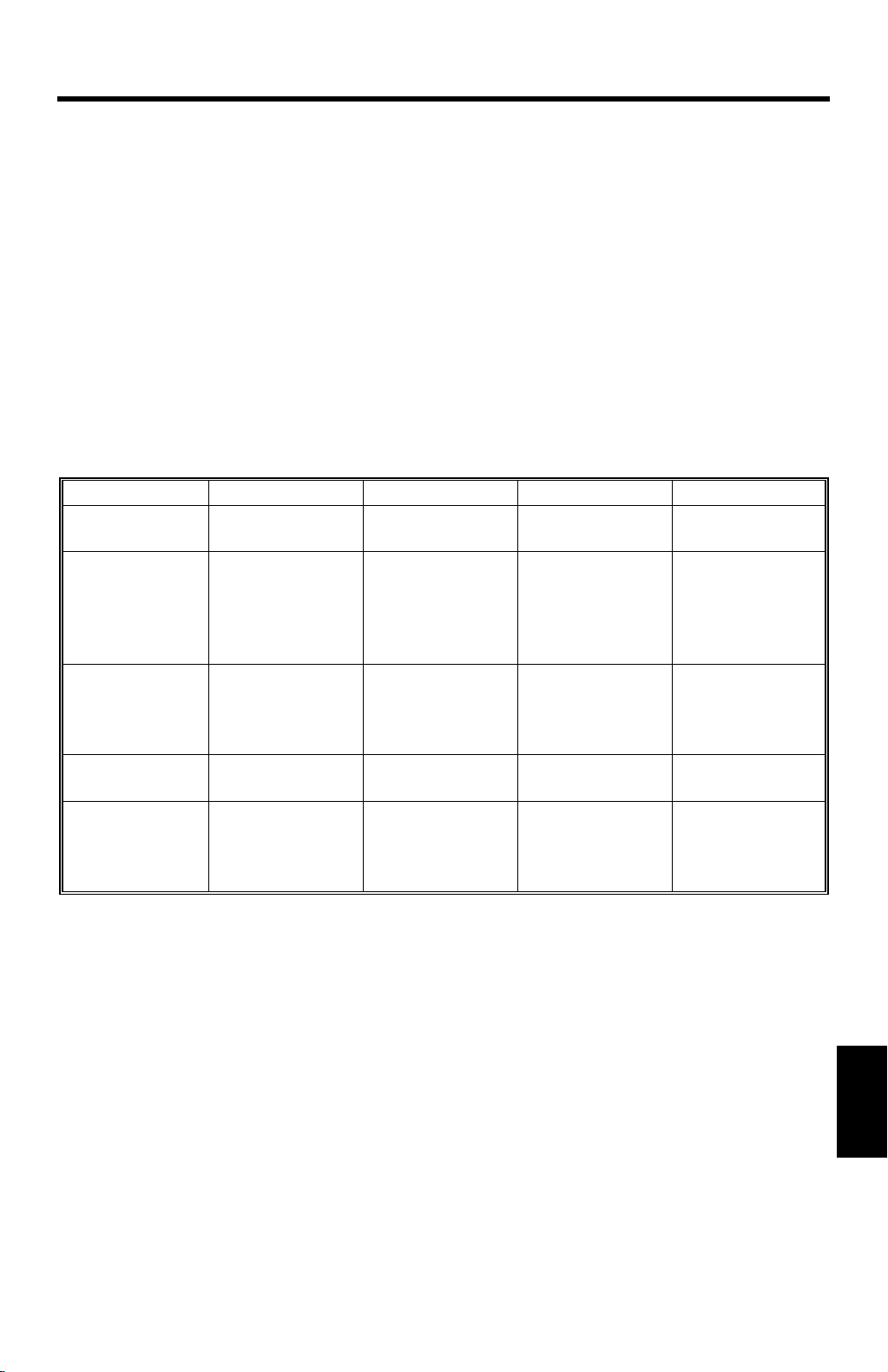
Staple Position:
a
c
d
e
a = 6 3 mm
A821V500.WMF
A821V501.WMF
b
b = 6 3 mm
c = 6 3 mm
d = 66 3 mm
a
e = 132 2 mm
f = 6 3 mm
g = 116.5 2 mm
g
= 45 5
f
g
Staple Replenishment: Cartridge refill (5,000 piec es/cartridge)
Power Source: DC24 V (from copier)
Power Consumption: Average:
less than 60 W (without punch)
less than 70 W (with punch)
Maximum:
in sort/stack mode:
less than 60 W (without punch)
less than 70 W (with punch)
in staple mode:
less than 45 W
A821-2
Page 4
21 September 1998 SPECIFICATIONS
Dimensions (W x D x H): 566 x 583 x 990
Weight: Approximately 50 kg
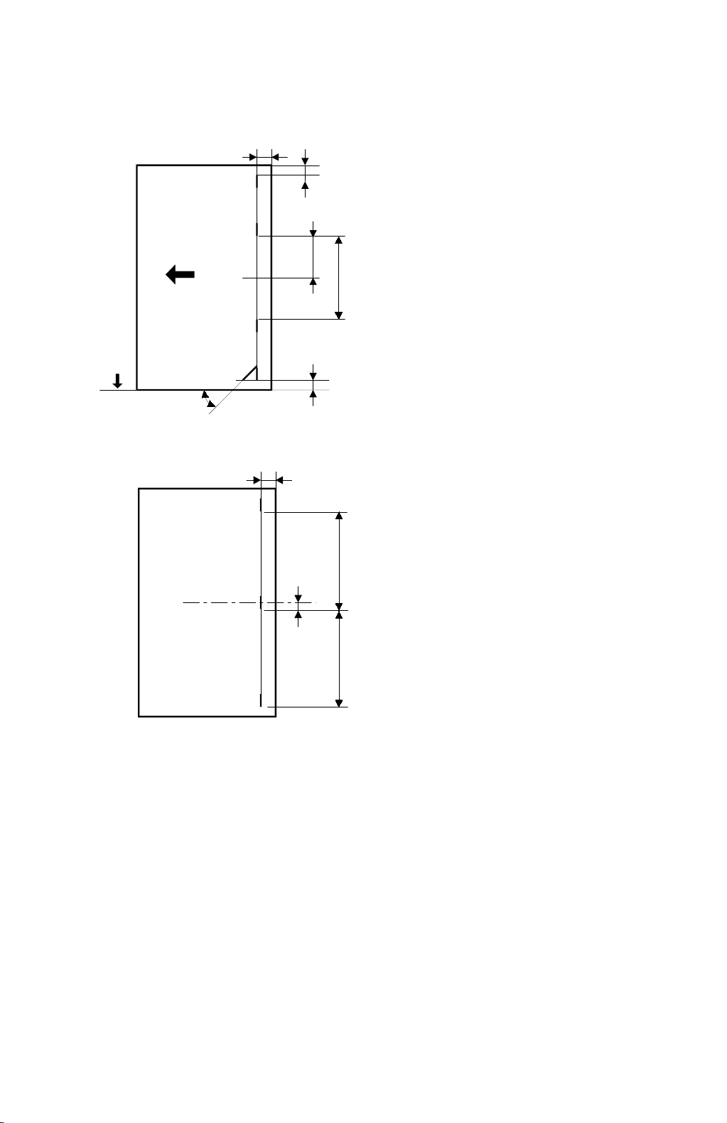
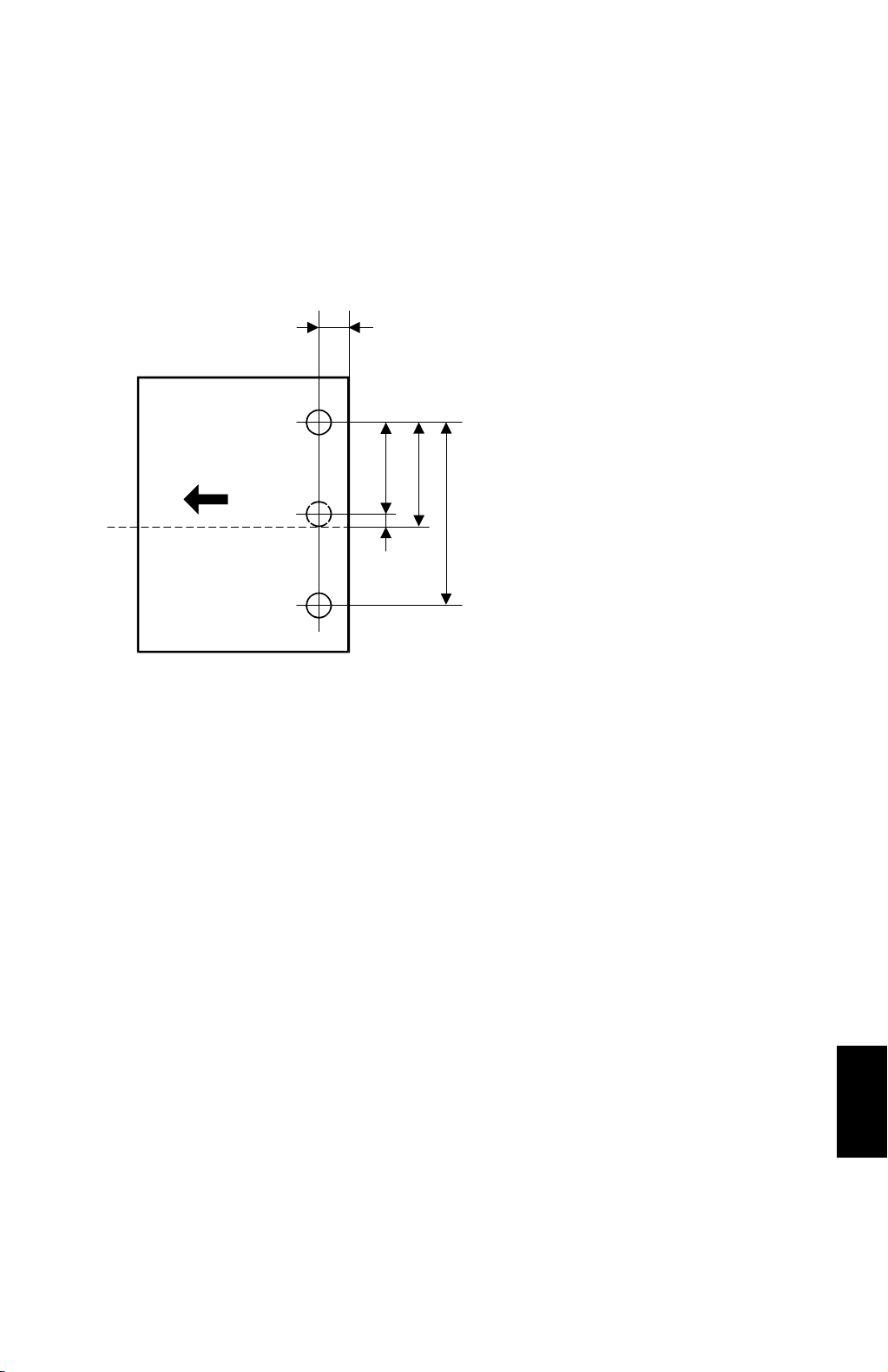
Punch Position:
a
2 Holes (European version)
a = 12 3 mm
A821V502.WMF
b = 40 3 mm
c = 80 1 mm
d
b
c
3 Holes (U.S.A. version)
a = 9.5 (
c = 216 (8
") 3 mm
3/8
") 1 mm
1/2
d’
d = 108 (4
") 1 mm
1/4
d’ = 3 mm
Punch Hole Size
2 Holes: = 6.5 0.5 mm
3 Holes: = 8.0 0.5 mm
A821-3
Options
Page 5
COMPONENT LAYOUT 21 September 1998
1.2 COMPONENT LAYOUT
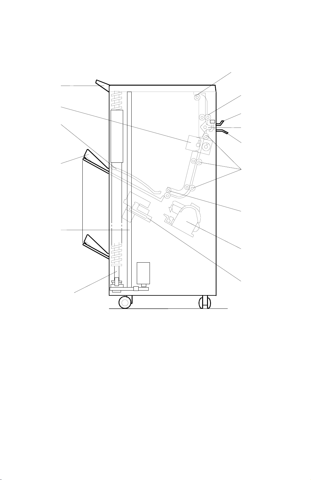
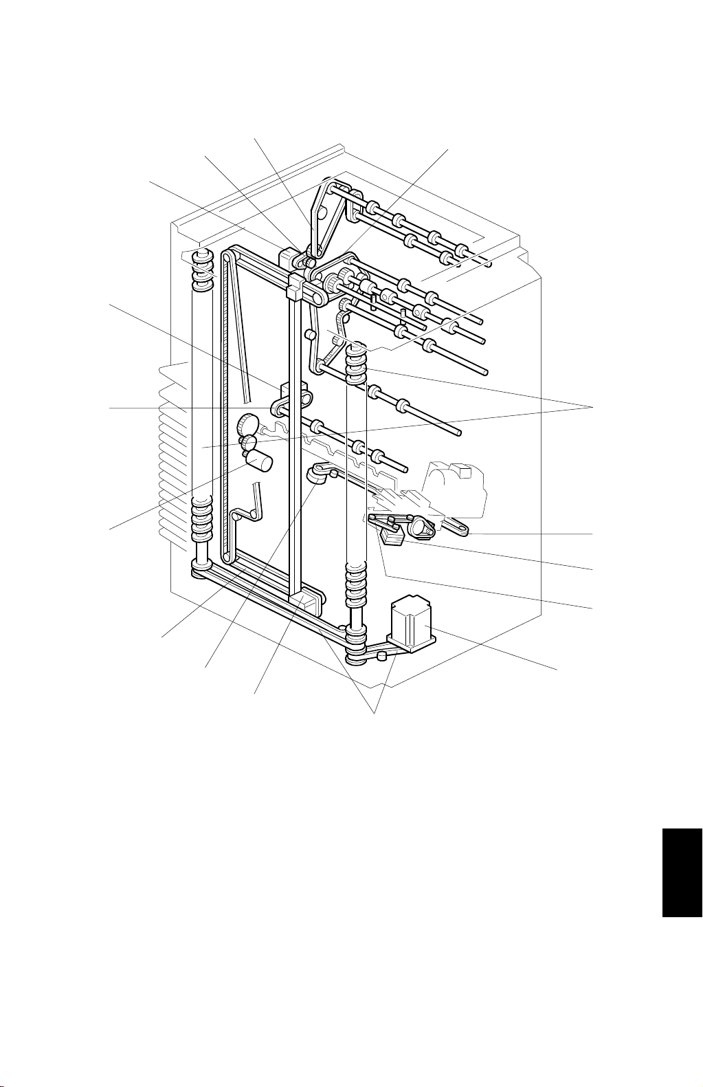
1.2.1 MECHANICAL COMPONENT LAYOUT
2
1
3
15
4
14
13
12
5
6
7
8
9
10
11
1. Proof Tray
2. Proof Exit Rollers
3. Proof Transport Rollers
4. Upper Entrance Guide
5. Turn Gate
6. Lower Entrance Guide
7. Sorter Transport Rollers
8. Sorter Exit Rollers
A821V503.WMF
9. Staple Unit
10. Grip Assembly
11. Helical Wheels
12. Jogger Plate
13. Bins
14. Upper Guide Plate
15. Punch Unit (Punch version only)
A821-4
Page 6
21 September 1998 COMPONENT LAYOUT
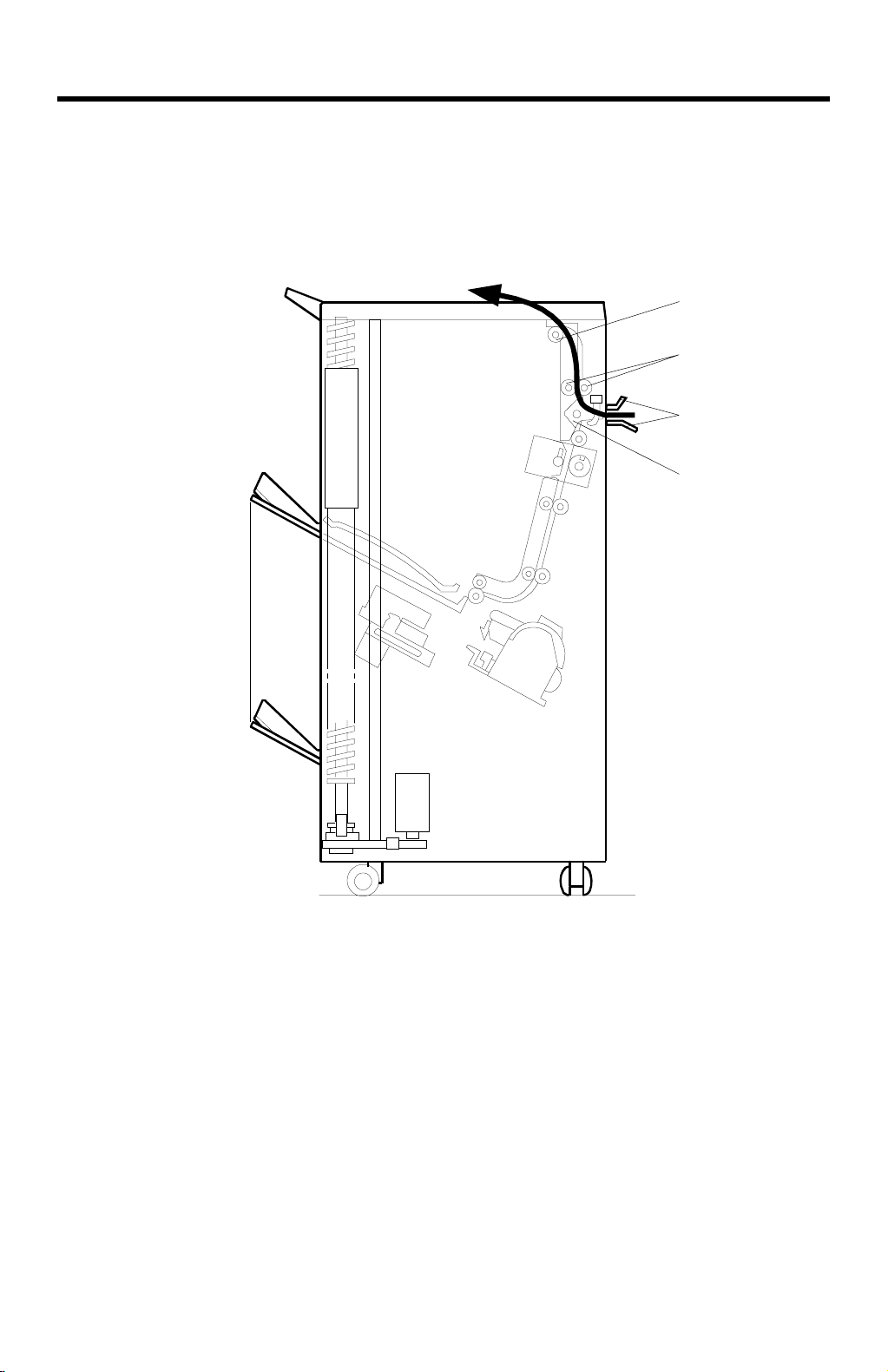
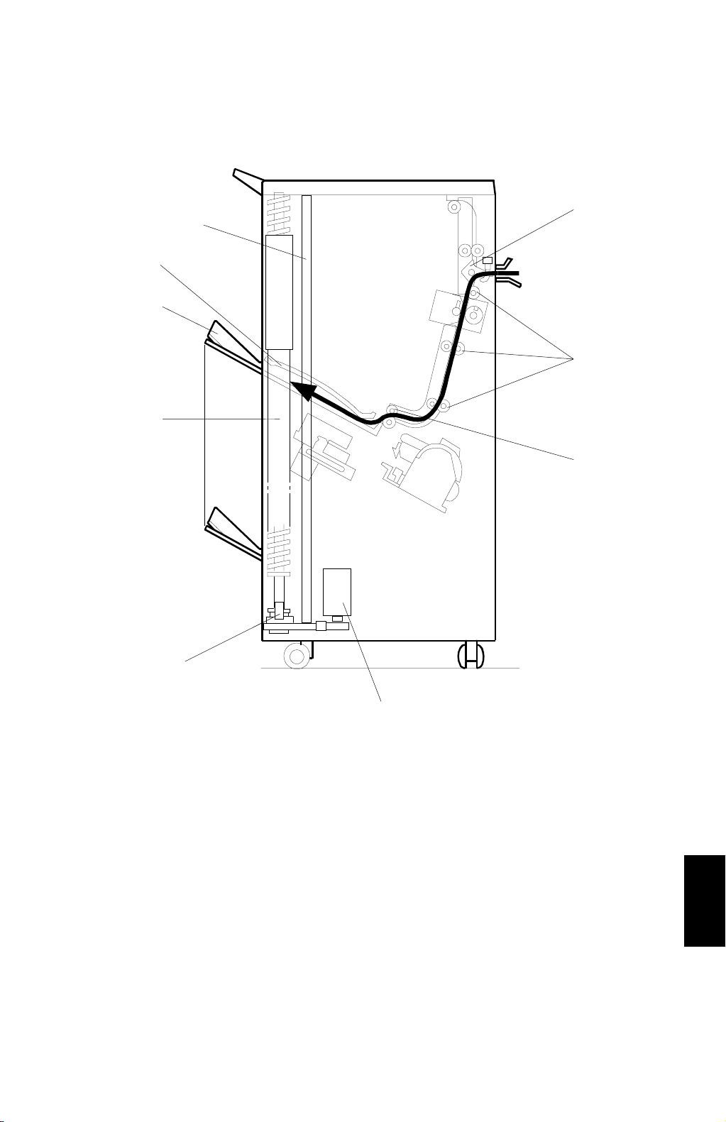
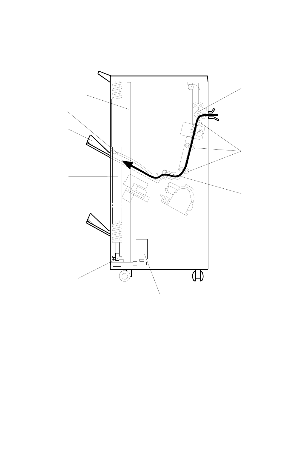
1.2.2 DRIVE LAYOUT
16
15
3
2
4
1
5
14
13
12
1. Main Motor
2. Main Drive Belt
3. Proof Drive Belt
4. Sorter Drive Belt
5. Helical Wheels
6. Staple Unit Drive Belt
11
9
10
A821V504.WMF
9. Bin Drive Motor
10. Wheel Drive Belts
11. Jogger Motor
12. Staple Unit Drive Motor
13. Jogger Drive Belts
14. Bin Rear Plate Drive Motor
6
7
8
Options
7. Gripper Motor
8. Grip Drive Belt
15. Sorter Exit Drive Belt
16. Sorter Exit Motor
A821-5
Page 7

ELECTRICAL COMPONENT DESCRIPTION 21 September 1998
1.3 ELECTRICAL COMPONENT DESCRIPTION
Refer to the electrical component layout on the reverse side of the point-to-point
diagram for the location of the components using the symbols and index numbers.
Symbol Name Function Index No.
Motors
M1 Tr ansport Drives the paper transport rollers. 32
M2 Exit Delivers the Paper into the bin. 26
M3 Bin Drives the bins up and down. 19
M4
M5 Bin Rear Plate Drives the bin rear plate up and down. 27
M6 Gr ip Grips the paper. 15
M7
M8
M9
M10 Punch Drives the punch shaft and roller. 31
Jogger Drives the jogger plate to jog the copies
against the front side plate.
Grip Shift Drives the grip unit forward and backward
into the bin.
Stapler
Stapler Unit Drives the stapler unit according to the
Feeds the staples and drive the stapler
hammer.
staple position and angle.
22
17
11
24
Switches
SW1 Door Safety Cuts the dc power when front door is open. 6
SW2 Cartridge Set Detects installation of the staple cartridge. 8
SW3 Staple End Detects the staple end. 9
Solenoids
SOL1
Sensors
S1 Entrance Detects the paper miss-feeds. 5
S2
S3 Proof Exit Detects the paper miss-feeds. 4
S4 Bin HP Detects if the bins are in the home position. 23
S5 Wheel Sensor Detects the bin position. 20
S6
S7 Grip HP Detects if the grip is in the home position. 16
S8
S9
S10
S11
Turn Gate Opens and closes the turn gate to direct the
copies into either the proof tray or bins.
Bin Jam Detects the miss-feeds and detects if there
is the paper in the bin.
Jogger HP Det e ct s if the jogger plat e is in the home
position.
Grip Shift MotorHPDetects if the grip unit is in the home
position.
Bin Rear Plate
Close
Bin Rear Plate
Open
Stapler HP
Detects if the bin rear plate is in the closed
position.
Detects if the bin rear plate is in the open
position.
Detects if the stapler hammer is in the home
position.
1
21
25
14
28
29
10
A821-6
Page 8

21 September 1998 ELECTRICAL COMPONENT DESCRIPTION
Symbol Name Function Index No.
S12
Stapler Unit HP
Detects if the stapler unit is in the home
position.
18
S13 Paper Detects whether copies are under hammer. 13
S14
Stapler Unit
Pull-out Position
Detects if the stapler unit is in the pullout
position.
12
S15 Punch HP Detects if the punch is in the home position. 33
S16
Punch waste
Overflow
Detects punch waste overflow and detects
whether the waste hopper is set or not.
7
PCBs
PCB1 Main Controls all sorter stapler functions. 30
PCB2
Bin Jam Sensor
LED
Provides the light to the bin jam sensor.
3
PCB3 Punch Control Controls the punch function. 2
A821-7
Options
Page 9
BASIC OPERATION 21 September 1998
2. DETAILED DESCRIPTION
2.1 BASIC OPERATION
2.1.1 NORMAL (PROOF MODE) AND SORT/STACK MODE
[D]
[C]
[A]
[B]
A821D500.WMF
Copies exiting the copier pass through the entrance guide plates [A] to the turn
gate section. The turn gate [B] will send copies either to the proof tray or to the
bins, depending on the mode.
Normal (Proof) Mode - (From the Turn Gate Section to the Proof Tray)
The turn gate solenoid energizes to turn the turn gate clockwise after pressing the
Start key. The main motor turns counter-clockwise to rotate the vertical transport
rollers [C] and proof exit roller [D]. The turn gate directs copies through the proof
transport section to the proof tray.
A821-8
Page 10
21 September 1998 BASIC OPERATION
Sort Mode (From the Turn Gate Section to the Bins)
[A]
[F]
[E]
[D]
[B]
[H]
[C]
[I]
[G]
A821D501.WMF
In this mode, the turn gate solenoid remains off to maintain the turn gate [A] in the
upper position. The main motor turns clockwise to rotate the sorter transport rollers
[B] and the exit motor rotates the exit rollers [C].
The turn gate directs copies to the sorter bins through the sorter transport section,
delivering the first copy between the top bin [D] and the upper guide plate [E]. The
jogger plate [F] then jogs to square the copies each time. Before the next copy
reaches the sorter exit roller, the bin drive motor [G] rotates and advances the bin
one step (the helical wheels [H] rotate once). When the cut out of the actuator
reaches below the wheel sensor [I], the bin drive motor turns off.
The bin advances with each delivered copy.
Options
A821-9
Page 11
BASIC OPERATION 21 September 1998
Stack Mode (From the Turn Gate Section to the Bins)
[A]
[F]
[E]
[D]
[B]
[H]
[C]
[I]
[G]
A821D502.WMF
As with sort mode, the turn gate solenoid stays off and the turn gate [A] stays up
after pressing the start key. The main motor turns clockwise to rotate the sorter
transport rollers [B] and the exit motor rotates the exit rollers [C].
The turn gate directs copies to the sorter bins through the sorter transport section,
delivering the copies between the top bin [D] and the upper guide plate [E]. The
jogger plate [F] then jogs back and forth to square the copies each time.
All copies from the copy run then feed into the first bin. When the final copy is
delivered, the wheel drive motor [G] turns and advances the bin one step (the
helical wheels [H] rotate once). When the cut out of the actuator reaches below the
wheel sensor [I], the bin drive motor turns off.
A821-10
Page 12
21 September 1998 BASIC OPERATION
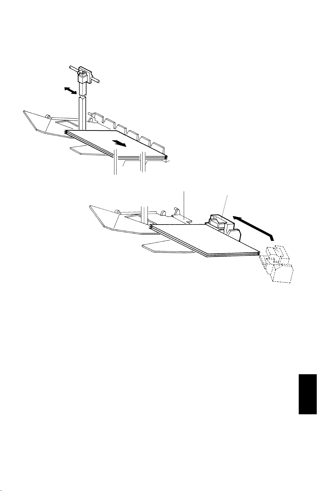
2.1.2 STAPLE MODE
A821D503.PCX
[A]
[B]
A821D504.PCX
After jogging the final set of copies, the staple unit staples the stacked copies as
follows: The grip arms move inside the front side plate and catch the paper. The
rear bin plate [A] is turned so it is flat with the sorter bin. The grip assembly brings
the copies down underneath the stapler [B]. The staple unit changes the position
(the position varies depending on the copy size and staple mode) and the stapler
staples the copies.
A821-11
Options
Page 13

BASIC OPERATION 21 September 1998
[A]
A821D505.PCX
The grip assembly brings the stapled copies back to the bin and the bin rear plate
[A] returns to the original position.
The grip assembly releases the copies and return to outside the front side plate so
as not to disturb the bin movement.
The bin advances one step.
After stapling the final set of copies, the staple unit returns to the home position.
There are two staple modes:
1) Automatic stapling:
In ADF mode, when the staple mode is selected before pressing the start
key, copies will be delivered to each b in and stapled automatically.
2) Manual stapling:
In sort mode, after sorting the copies in the bins, the stapling mechanism will
staple them after the user presses the manual staple key and selects the
staple position. In stack mode, manual stapling is impossible.
A821-12
Page 14
21 September 1998 TURN GATE SECTION
2.2 TURN GATE SECTION
[I]
[A]
[D]
[G]
[H]
[C]
[B]
A821D506.WMF
[C]
[E]
[F]
A821D507.WMF
The turn gate [A] sends copies to the proof tray or the sorter bins depending on the
mode. In proof mode, the turn gate solenoid [B] turns on and the main motor [C]
turns clockwise after pressing the start key.
The turn gate [A] directs copies upward through the proof transport section to the
proof tray. In this mode, both the proof drive belt [D] and sorter drive belt [E]
transmit the main motor drive. However, the one-way clutches in the drive gears [F]
for each sorter transport roller do not transmit the drive to the sorter transport
rollers.
In the sort, stack and staple modes, the turn gate solenoid stays off to direct copies
downward to the sorter transport section. After the user presses the start key, the
main motor [C] turns counter-clockwise. In this mode, the one-way clutch in the
pulley [G] prevents the main motor drive from transmitting to the proof drive belt
[D].
The entrance [H] and the proof exit [I] sensors monitor the paper jam.
A821-13
Options
Page 15
BIN DRIVE MECHANISM 21 September 1998
2.3 BIN DRIVE MECHANISM
[E]
[E]
[D]
15
30
[G]
[A]
45
[F]
40
40
A821D508.WMF
[B]
[C]
15
15
A821D509.WMF
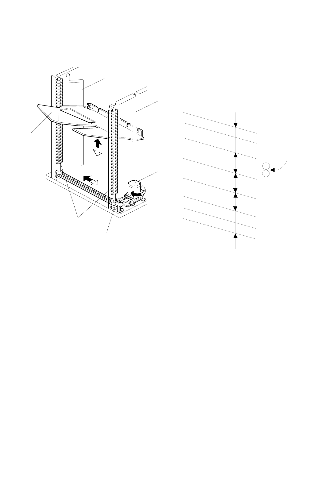
The bin drive mechanism moves the bins up and down to receive copies. The main
components in this mechanism are the bin drive motor [A], the two helical wheels
[B], the wheel sensor [C], and the bins [D] themselves. There are four pins on each
bin. Two of them fit in the slot on the helical wheels. Other two pins fit into the slots
[E] of the side frames. The pins slide up and down in these slots.
Two timing belts transmit the drive from the bin drive motor to the two helical
wheels. When it rotates clockwise, the bins lift (black arrow) and when it rotates
counter-clockwise, the bins lower (white arrow). There is a wheel sensor actuator
on the front helical wheel; the actuator has a slot, which detects when the helical
wheel has rotated 360 degrees.
When the bins advance, the helical wheels rotate once (360 degrees) for each
step.
The spiral pitch on the helical wheel is greater when bins are at the staple and
paper exit area than elsewhere. Consequently, the amount of bin shift is greater
when bins are at the staple and paper exit area. This leaves enough space to
staple [F] and stack paper [G] and reduces the total machine height.
A821-14
Page 16
21 September 1998 BIN HOME POSITION
2.4 BIN HOME POSITION
[A]
[E]
A821D510.WMF
[B]
[D]
[C]
A821D511.WMF
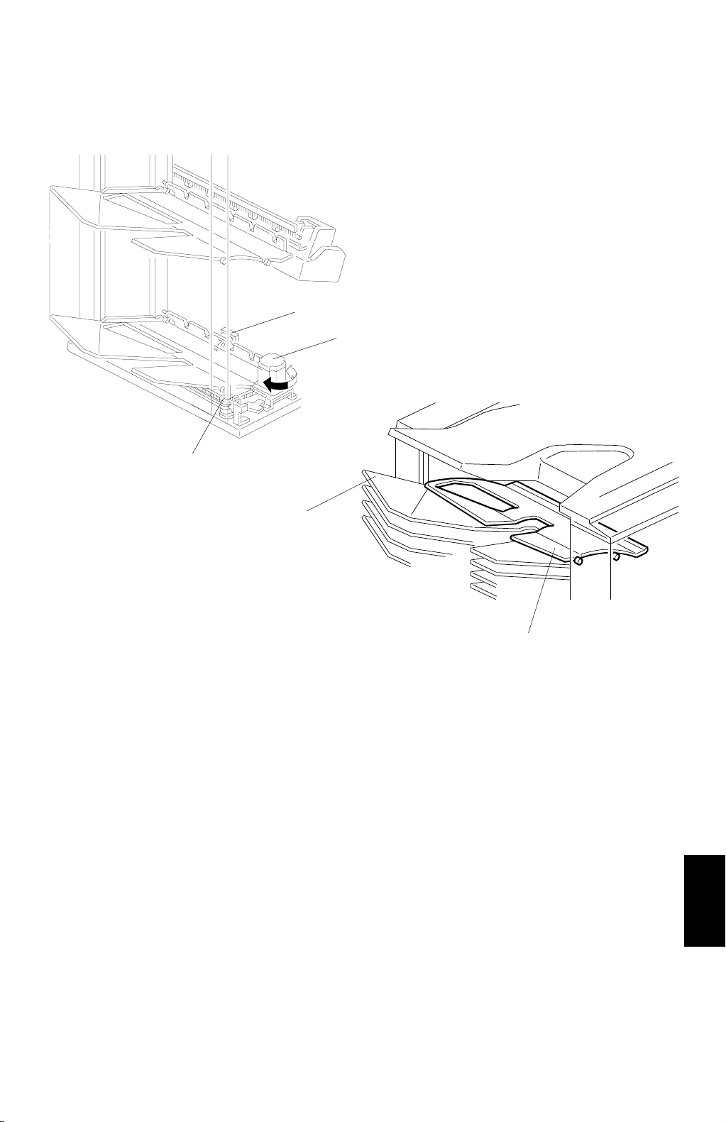
The bin HP sensor [A] and the wheel sensor [B] ensure that the sorter exit roller is
between the upper guide plate [C] and the 1st bin [D] when all the bins are in their
home position.
After turning on the main switch, the bin lift motor [E] lowers the bins (turns
counter-clockwise) until the bottom bin actuates the bin HP sensor. Then, the bin
lift motor raises the bins (turns clockwise) until the wheel sensor activates.
Consequently, the bins are in the home position.
A821-15
Options
Page 17
JOGGER SECTION 21 September 1998
2.5 JOGGER SECTION
[B]
Copier Main
Motor
ON
[A]
Jam Sensor
A821D512.WMF
Jogger Motor
300 ms
A821D513.WMF
After pressing the start key in the sort, staple and stack modes, the copier sends
the paper size information to the sorter/stapler. In accordance with this data, the
jogger motor [A] drives the jogger plate [B] from the jogger HP to a width 10 mm
wider than the selected paper. 300 ms after the trailing edge of the copy passes
underneath the jam sensor, the jogger motor rotates forward and in reverse. This
makes the jogger plate push all the copies against the front side plate to square the
sheets. When the jogger plate pushes the paper, the plate shifts to a position 5 mm
wider than the paper size when the bins lift. It shifts to a position 1 mm narrower
than the paper size when the bins lowers.
The jogger plate returns to 10 mm away from the selected paper size for the next
copy.
When the bin sensor dete cts that all copies are no longer in the bins after jogging
finishes, the jogger plate returns to its home position.
A821-16
Page 18

21 September 1998 JOGGER SECTION
[C]
[B]
[D]
A821D514.WMF
[E]
[C]
[A]
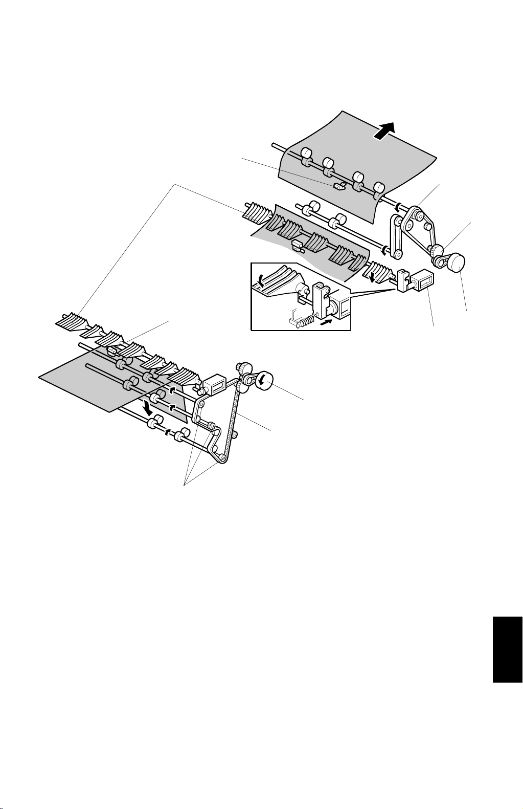
Normally, all rollers in the sorter/stapler transport the paper at a speed of 345 mm/s
(A246) or 450 mm/s (A247/A248). To have enough jogging time, the rotation speed
for the sorter exit motor [A] changes, to transport the paper quickly and stack it
smoothly into the bins, in the following manner:
345 mm/s (A246) or 450 mm/s (A247/A248): When the sorter exit roller [B] catches
the leading edge of the paper
1,000 mm/s: After the jam sensors [C] detects the leading edge of the paper
600 mm/s: When releasing the trailing edge of the paper
The transport roller [D] turns at a constant speed of 345 mm/s (A246) or 450 mm/s
(A247/A248). However, when the sorter exit roller [B] rotates quickly, the transport
rollers do the same with the pulled paper. This occurs because of the one-way
clutch in the drive gear [E].
Jogger off Conditions
1. Under the following conditions, the jogger plate does not jog after copies are
delivered to the bins.
If paper is loaded in a bin by hand while the selecting sort/stack or staple
mode.
If the selected paper size does not match stapling specifications.
If copy of smaller width is delivered in the bins later in the “Mixed sizes”
mode.
Options
2. If paper is in a bin before turning on the main switch, the sort/stack mode is
disabled after the user touches the sort key.
A821-17
Page 19

BIN REAR PLATE DRIVE SECTION 21 September 1998
2.6 BIN REAR PLATE DRIVE SECTION
Fig. 1
[I]
[A]
Fig. 2
[A]
[F]
[F]
[C]
[G]
[J]
[B]
[D]
[E]
[H]
[I]
[G]
A821D515.WMF
The bin rear plates [A] stand up as shown (Fig. 1). They are lowered only during
stapling as shown (Fig. 2).
In staple mode, when the jogger plate has jogged all copies, the bin rear plate drive
motor [B] rotates a gear [C]. The gear [C] drives the piston rod [D], pushing the
lever [E] down.
The holder [F] engaging the pin [G] on the bin rear plate lowers in accordance with
the lever [E] position. Thus, the bin rear plate becomes flat so as not to interfere
with the copies brought to the staple position by the grip assembly.
During stapling, the actuator [I] interrupts the rear plate open sensor [H] (Fig. 2) for
the bin.
When the bin rear plates ar e in their home position, the ac tuator [I] interrupts their
HP sensor [J] (Fig. 1).
Under this condition, a pin [G] enters the holder [F] or passes through it.
After stapling is complete and the stapled paper returns to the bin, the gear [C]
rotates 180 degrees and the bin rear plate returns to its home position.
A821-18
Page 20

21 September 1998 GRIP ASSEMBLY
2.7 GRIP ASSEMBLY
The grip assembly catches the jogged copies and moves them to the staple unit.
After stapling, the grip assembly catches the copies again and moves them back.
The grip assembly consists of grip arms, and the grip and grip shift motors. The
grip arms catch the paper. The grip motor moves the grip arms inside and outside,
and enables the grip arms to catch the paper. The grip shift motor causes the grip
arms to carry the paper to the staple unit.
A821-19
Options
Page 21

GRIP ASSEMBLY 21 September 1998
2.7.1 GRIP MOTOR
[B]
[A]
[C]
[F]
A821D516.WMF
[E]
[D]
A821D517.WMF
When the grip motor [A] rotates seve ral times, the lever [B] moves inside and
pushes the grip arms [C]. After the grip motor rotates some more, the bracket [D]
moves upward and pushes the pressure arm [E]. When the pressure arm move
upward, the grip springs [F] attract the upper grip arms, then the grip arms catch
the paper.
[C]
A821-20
Page 22

21 September 1998 GRIP ASSEMBLY
2.7.2 GRIP SHIFT MOTOR
[A]
[B]
A821D518.WMF
The grip shift motor [A], a stepper motor, enables the grip arms to carry the paper
to the staple unit and after stapling make it carry them back. The grip shift motor
HP sensor [B] is actuated while the gripper is in the home (grip) position. The
sorter/stapler main control board sends the appropriate pulses to the grip shift
motor to determine the grip and staple positions. Vertical staple positions are
adjusted by changing the number of the stepping motor pulses from the home
position (SP1-11-1 “Staple Position Adjustment”).
A821-21
Options
Page 23

STAPLE UNIT 21 September 1998
2.8 STAPLE UNIT
2.8.1 STAPLE UNIT DRIVE MECHANISM
[B]
[A]
A821D519.WMF
The staple unit moves from the home position (top slant position) to the rear side of
the machine in order to change the staple position. The staple HP sensor [A]
activates when the staple unit is in the home position. In Top Slant mode, the
stapler is only at the home position. In “Top” (or “Bottom”) single staple mode, the
staple unit moves to the front (or rear) single staple position and stays there until
stapling is complete. It then returns to the home position. In “2 Staples” mode or
“Bottom” single staple mode; the staple positions differ according to the paper size.
The staple unit drive motor [B] is a stepper motor, and the number of steps from
the home position determine the staple position.
In “2 Staples” mode, the staple unit goes back and forth to staple the two positions.
Horizontal staple positions are adjusted by changing the number of stepping motor
pulses from the home position (SP1-11-1”Staple Position Adjustment”).
A821-22
Page 24

21 September 1998 STAPLE UNIT
2.8.2 STAPLER
[D]
[B]
[C]
[I]
[E]
[A]
A821D520.WMF
[F]
[H]
[G]
A821D521.WMF
The stapler motor [A] drives the staple sheet drive belt.
The staple sheets go under the hammer [B].
The stapler motor drives the staple hammer via gears [C], two eccentric cams [D].
When the grip brings the aligned copies to the staple position, the stapler motor
starts rotating. When the cams complete one rotation, the staple HP sensor [E] is
de-actuated. The stapler motor then stops.
When the paper sensor [F] in the grip assembly does not detect that the copies are
under the hammer, the stapler motor does not rotate.
There are two sensors in the staple unit. One is the staple end sensor [G], which
detects staple end conditions. The other is the cartridge set sensor [H],which
detects when the staple cartridge is not installed.
Options
The staple cartridge has a clinch area [I], a deposit for jammed staples. Operators
can remove the jammed staples from the cartridge.
A821-23
Page 25

STAPLE UNIT 21 September 1998
Staple Prohibit Conditions
1. Under the following conditions, staple mode is disabled after pressing the
staple key on the operation panel:
If paper is in the bin before turning on the main switch.
If the selected paper size does not match stapling specifications.
If the paper comes from the by-pass feed table.
2. Under the following conditions, staple mode is canceled:
If paper is manually loaded into a bin after selecting staple mode.
If only one sheet is delivered to the bin.
If the stack, slip-sheet or interrupt modes are selected.
3. Under the following conditions, manual stapling mode in sort mode is
prohibited:
If paper is manually loaded into a bin after selecting sort mode.
If the paper size in the bin does not match stapling specifications.
If only one sheet is delivered to the bin.
The delivery of a smaller width paper to the bin later in “Mixed Sizes” mode.
If copies already stapled, remain in the bin.
A821-24
Page 26

21 September 1998 STAPLE UNIT
2.8.3 PUNCH MECHANISM
[C]
[E]
[B]
[D]
[A]
A821D522.WMF
[G]
[F]
A821D523.WMF
The punch unit [A], which is in the copy transport path, makes punched holes for
every copy paper in the punch mode. The punch drive motor [B] (stepping motor)
drives the punch unit. At the appropriate timing after the entrance sensor [C]
detects the trailing edge of the copy paper, the punch drive motor rotates and the
hole puncher [D] makes holes in the paper. The punch HP sensor [E] detects if the
hole puncher is in the home position. The punch collection cartridge [F] collects
punch rubbish (waste). When the punch rubbish (waste) overflow sensor [G]
detects the overflow condition, the machine indicates the condition in the operation
panel after the punch job is done.
Options
A821-25
Page 27

STAPLE UNIT 21 September 1998
2.8.4 STAPLE UNIT PULLED-OUT MECHANISM
[C]
[B]
[D]
[A]
A821D524.WMF
For easy staple cartridge replenishment, the staple unit can be pulled-out from the
front. Pulling out the R3 release grip [A] releases the stopper and enables the
staple unit to be removed (staple unit pulled-out position). In this position, the
stopper arm [B] locks the staple unit by dropping the arm to the edge of bracket [C].
When the staple unit is no t in completely (the staple un it is between the staple unit
HP and the staple unit pulled-out positions [D]), the LCD displays a message
advising the user to set the staple unit in the home position.
A821-26
Page 28
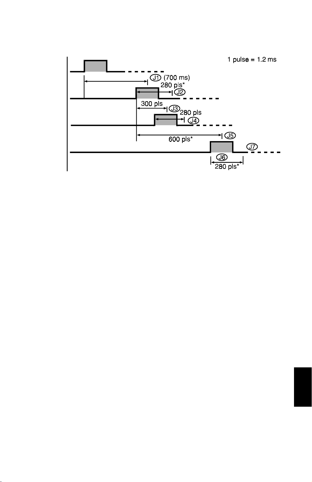
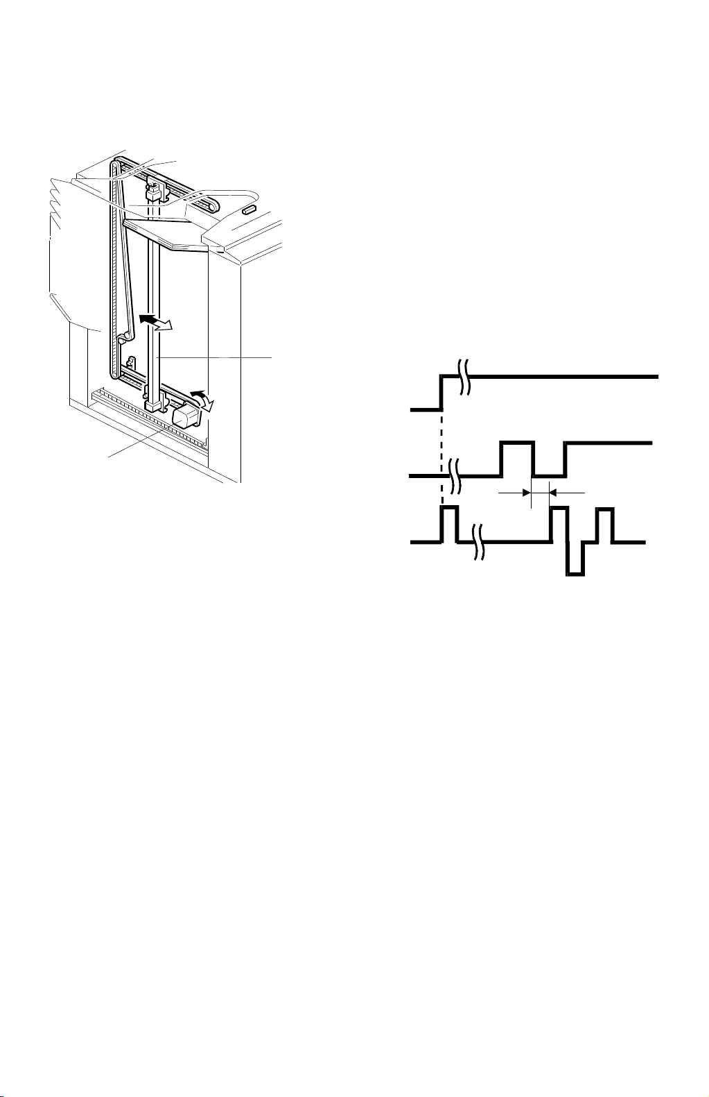
21 September 1998 JAM DETECTION
2.9 JAM DETECTION
Copier Exit
Sensor
Entrance
Sensor
Proof Exit
Sensor
Jam
Sensor
* Timing depends on the paper sizes.
A821D525.WMF
Sorter Jams
The main control board for the sorter /st apl er detects jams under the following
conditions: (In these cases, a jam signal is sent to the copier, the copier stops the
paper feed and indicates a sorter miss-feed.)
Normal (Proof) Mode
J1: The entrance sensor has not turned on for the 700 ms after the copier exit
sensor turns on.
J2: The entrance sensor stays on for the appropriate number of pulses (for
example, 280 pulses for A4 sideways) or more.
J3: The proof exit sensor has not turned on for 300 pulses after the entrance
sensor turns on.
J4: The proof exit sensor stays on for the appropriate number of pulses (for
example, 280 pulses for A4 sideways) or more.
In Sort/Stack or Staple Mode
J1 and J2: Same as the Normal mode.
J5: The jam sensor has not turned on for 600 pulses after the entrance sensor
turns on.
J6: The jam sensor stays on for the appropriate number of pulses (for example,
280 pulses for A4 sideways) or more.
J7: The jam sensor turns on while the bin drive motor turns on.
A821-27
Options
Page 29

TIMING CHART 21 September 1998
2.10 TIMING CHART
2.10.1 SORTER/STAPLER TIMING CHART (PROOF MODE)
Signal
Motor ON
Proof mode
Paper size
data
Exit signal
Sorter busy
S/S exit
signal
S/S main
motor ON
Entrance Sensor
Proof exit Sensor
Timing Chart
A821D526.WMF
A821-28
Page 30

21 September 1998 TIMING CHART
2.10.2 SORTER/STAPLER TIMING CHART (STAPLE MODE)
Motor ON
Staple ON
Proof mode
Staple mode
Exit signal
Paper size data
Bin data
Sorter busy
S/S Exit signal
Proof count
Job complete
Entrance sensor
Jam sensor
Sorter exit motor
Sorter main motor
Jogger motor
Staple unit drive
motor
Grip shift motor
Grip shift motor
HP sensor
Grip motor
Grip motor HP
sensor
Staple motor
Bin rear plate drive
motor
Bin drive motor
NOTE 1
300 ms
NOTE 1
NOTE 2
NOTE 3
A821D527.WMF
Options
NOTE:
1) Jogger motor on/off time differs depending on the paper size.
2) Staple unit drive motor off time differs depending on the paper size.
3) Bin drive motor off time differs depending on the number of copy sets.
A821-29
Page 31

SERVICE TABLES (MAIN CONTROL BOARD) 21 September 1998
3. SP MODE
3.1 SERVICE TABLES (MAIN CONTROL BOARD)
3.1.1 DIP SWITCHES
DIP SW 100
Function 1 2 3 4
Standard setting 0 0 — —
Raises all bins to the top position. 1 0 — —
Free run 0 1 — —
Initialization 1 1 — —
2 Hole punch setting (Europe) — — 0 0
3 Hole punch setting (U.S.A.) — — 0 1
DIP SW 101
DIP SW 102
Standard Position 0 0 0 —
0.5 mm 1 0 0 0/1
0.1 mm 0 1 0 0/1
1.5 mm 1 1 0 0/1
2.0 mm 0 0 1 0/1
2.5 mm 1 0 1 0/1
3.0 mm 0 1 1 0/1
3.5 mm 1 1 1 0/1
direction (See the illustration below.)
–
+ direction (See the illustration below.) — — — 1
Vertical Staple Position Adjustment
Horizontal Staple Position Adjustment
Adjustment Value 1 2 3 4
——— 0
0: OFF 1: ON
NOTE:
The adjustment value and the combination of the dip switch positions are
the same on DIP SW 101 and DIP SW 102.
Feed direction
Feed direction
+ direction
– direction
+ direction
A821M500.WMF
A821-30
– direction
Page 32

21 September 1998 SERVICE TABLES (MAIN CONTROL BOARD)
3.1.2 PUNCH POSITION
DPS 100
Adjustment value 1234
Standard (3 Holes)
9.5 mm from trailing edge
Standard (2 Holes)
12 mm from trailing edge
—— 0 1
—— 0 0
Feed direction
A821M501.WMF
3.1.3 TEST POINTS
Number Function
TP100 GND
TP101 +5 V
3.1.4 FUSES
FUSES Connected Point Rated Current and Voltage
FUSES100 CN100-1 (+24 V) 250 V T5A
A821-31
Options
Page 33

EXTERIOR COVER REMOVAL 21 September 1998
4. REPLACEMENTS AND ADJUSTMENTS
4.1 EXTERIOR COVER REMOVAL
[A]
[D]
[B]
[E]
[C]
Front Door Removal
1. Remove the proof tray [A] (2 screws).
2. Open the front door [B] and push away the staple unit.
3. Remove the front inner cover [C] (3 screws).
4. Lift up the front door and remove it.
Bottom Plate Removal
1. Remove the rear cover [D] (4 screws).
2. Remove the bottom plate [E] (2 screws).
NOTE:
The proof tray, front inner cover, front left cover, and rear cover can be
removed without removing any other parts.
A821R500.WMF
A821-32
Page 34

21 September 1998 STAPLER REMOVAL AND REINSTALLATION
4.2 STAPLER REMOVAL AND REINSTALLATION
[A]
[F]
A821R501.WMF
[B]
[E]
A821R502.WMF
1. Return the staple unit [A] to the home position by pulling out the staple unit.
2. Pull out the R3 release lever [B] and pull out the staple unit.
3. Remove the harness cover [C].
4. Remove the staple unit [D] (1 connector and 1 screw).
[D]
[C]
NOTE:
When re-assembling the parts, hook the cut out [E] to the shoulder screw
[F].
Options
A821-33
Page 35

JOGGER PLATE REMOVAL AND INSTALLATIOIN 21 September 1998
4.3 JOGGER PLATE REMOVAL AND INSTALLATIOIN
[A]
[B]
[C]
[E]
A821R503.WMF
[D]
A821R504.WMF
Removal
1. Remove the proof tray. (Refer to Exterior Cover Removal, section 4.1.)
2. Release the spring [A] of the upper jogger holder [B], and then pull out the
jogger plate [C].
Installation
1. Insert the jogger plate through the upper holder [B].
2. Push down the jogger plate towards the lower holder [D].
3. Set the jogger plate in the lower holder [D].
4. Hook the spring [A] of the upper jogger holder to the stopper [E].
A821-34
Page 36

21 September 1998 BINS REMOVAL
4.4 BINS REMOVAL
Removal
[A]
[D]
A821R505.WMF
[C]
[B]
A821R542.WMF
1. Remove the rear cover.
2. Raise all bins to the highest position by turning on DIP SW100-1 on the main
PCB for the sorter, then turn off the main switch of the copier.
3. Remove the jogger plate (refer to Jogger Plate Removal) then move the upper
jogger holder [A] to the front side.
4. Remove the rear cover then remove the bottom plate to access the drive belt.
(Refer to Exterior Cover Removal section.)
5. Manually rotate the helical wheel drive belt [B] and move up the top guide [C]
until the three guide pins [D] reach the top of the helical wheel as shown.
A821-35
Options
Page 37

BINS REMOVAL 21 September 1998
[D]
[B]
[A] [C]
A821R507.WMF
[F]
[H]
[E]
[G]
A821R508.WMF
6. Remove the top guide by releasing two pins [A and B] from the cutouts [C and
D] at the end of the bin guide slots. Then remove the pins [E and F] from the
cutouts [G and H].
7. Move the next bin to the top position by manually rotating the helical wheel
drive belt and remove it according to the removal procedure for the top guide
(step 5 and 6).
8. Remove the other nineteen bins by repeating step 7.
A821-36
Page 38

21 September 1998 BINS REMOVAL
Installation
[H] [A]
[B]
[J]
[D]
[E]
[G]
A821R509.WMF
[F]
[E]
A821R510.WMF
[I]
1. While holding the bin rear plate [A] straight, insert the rear right guide pin [B]
into the slot [C], and then lower the rear guide pin to the corner [D].
2. While still holding the bin rear plate straight, in sert the front right guide pin [E] to
guide slot [F].
3. Insert the other guide pins [G] and [H] to the slots [I] and [J].
Options
A821-37
Page 39

BINS REMOVAL 21 September 1998
[B]
[A]
A821R511.WMF
Good No Good
A821R512.WMF
4. Manually rotate the helical wheel drive belt [A] and lower the bin.
NOTE:
Before installing the next bin, rotate the helical wheels only once.
Otherwise, the distance between the guide pins [B] become uneven
and the bin tilts.
5. Set all bins and the top cover by repeating steps 1 to 4.
6. Re-install the jogger plate and all covers.
A821-38
Page 40

21 September 1998 MAIN MOTOR REMOVAL
4.5 MAIN MOTOR REMOVAL
[A]
[B]
1. Remove the rear cover (4 screws).
2. Disconnect the connector [A].
3. Remove the bracket [B] (4 screws) for the main motor.
A821R513.WMF
A821-39
Options
Page 41

GRIP ASSEMBLY REMOVAL 21 September 1998
4.6 GRIP ASSEMBLY REMOVAL
[A]
[B]
[D]
[C]
A821R514.WMF
1. Open the front door then remove the front inner cover. (Refer to Exterior Cover
Removal, section 4.1.)
2. Disconnect the four connectors [A to D].
NOTE:
When re-connecting the connectors, connect the longer harness [A] to
grip shift motor HP sensor and the shorter harness [B] to grip motor HP
sensor.
3. Remove the grip assembly.
A821-40
Page 42

21 September 1998 UPPER GRIP ASSEMBLY REMOVAL
4.7 UPPER GRIP ASSEMBLY REMOVAL
[C]
[A]
[B]
A821R515.WMF
1. Remove the grip assembly. (Refer to Grip Assembly Removal, section 4.6.)
2. Remove the timing belt securing bracket [A] (1 screw).
3. Remove the grip shift shaft [B] (1 E-ring).
4. While closing the upper-grip assembly [C], remove it.
Options
A821-41
Page 43
GRIP SHIFT MOTOR REMOVAL 21 September 1998
4.8 GRIP SHIFT MOTOR REMOVAL
[A]
[B]
A821R516.WMF
1. Remove the upper grip assembly. (Refe r to Upper Grip Assembly Removal,
section 4.7.)
2. Mark the original position of the screw [A] securing the grip shift motor [B].
3. Remove the grip shift motor.
NOTE:
When re-inst alling the grip shift motor, place the motor at the original
position by referring to the mark you made.
A821-42
Page 44

21 September 1998 GRIP MOTOR AND SENSORS REMOVAL
4.9 GRIP MOTOR AND SENSORS REMOVAL
4.9.1 GRIP MOTOR/GRIP MOTOR HP SENSOR/GRIP SHIFT
MOTOR HP SENSOR REMOVAL
[D]
[B]
[C]
[A]
A821R517.WMF
1. Remove the grip assembly. (Refer to Grip Assembly Removal, section 4.6.)
2. Replace the grip motor HP sensor [A].
3. Replace the grip shift motor HP Sensor [B].
4. Mark the original position of the screw [C] securing the grip motor [D].
5. Remove the grip motor.
NOTE:
When re-inst alling the grip moto r, place the motor at the original
position by referring to the mark you made.
Options
A821-43
Page 45

MAIN CONTROL BOARD REPLACEMENT 21 September 1998
4.10 MAIN CONTROL BOARD REPLACEMENT
[A]
A821R518.WMF
1. Remove the rear cover (refer to Exterior Cover Removal, section 4.1) then
disconnect all connectors (15 connectors and 1 fiber optics connector).
2. Remove the main control board [A] (6 studs).
3. Install the new main control board and set all connectors.
4. Position DIP SW 100, 101 and 102 as on the original main control board (DIP
SW 101 and 102 are for staple position adjustment and DIP SW 100 is for SP
mode).
5. Turn on the main switch for the copier, and then confirm the staple position. If
incorrect, adjust the staple position. (Refer to the Staple Position Adjustment,
section 4.11.)
A821-44
Page 46

21 September 1998 STAPLE POSITION ADJUSTMENT
4.11 STAPLE POSITION ADJUSTMENT
Adjustment Standard
Staple Position:
A821R539.WMF
a
a
c
g
d
e
f
g
b
A821R540.WMF
a = 6 3 mm
b = 6 3 mm
c = 6 3 mm
e = 132 2 mm
f = 6 3 mm
g = 116.5 2 mm
d = 66 3 mm
= 45 5
Adjustment
[A]
[B]
A821R538.PCX
Both the vertical and the horizontal staple positions are adjustable as follows:
1. Enter SP1-11-1 (Staple Position Adjustment).
2. Adjust the vertical staple position by touching the “–,” “+” keys [A] and the
horizontal staple position by touching the “–,” “+” keys [B].
NOTE:
0.5 mm/step
Options
A821-45
Page 47

PUNCH POSITION ADJUSTMENT STANDARD 21 September 1998
4.12 PUNCH POSITION ADJUSTMENT STANDARD
Punch Position:
a
2 Holes (European version)
a = 12 3 mm
A821R541.WMF
Adjustment
b = 40 3 mm
c = 80 1 mm
d
b
c
3 Holes (U.S.A. version)
a = 9.5 (
c = 216 (8
") 3 mm
3/8
") 1 mm
1/2
d’
d = 108 (4
") 1 mm
1/4
d’ = 3 mm
Punch Hole Size
2 Holes: = 6.5 0.5 mm
3 Holes: = 8.0 0.5 mm
[A]
A821R538.PCX
1. Enter SP1-11-2 (Punch Hole Position Adjustment).
2. Adjust the punch position by touching the “–,” “+” keys [A] (vertical position
only).
NOTE:
1 mm/step
A821-46
Page 48

21 September 1998 HELICAL WHEELS REMOVAL
4.13 HELICAL WHEELS REMOVAL
Removal
Before removing the helical wheels, remove all bins and all exterior covers.
(Refer to Exterior Cover, section 4.1, and Bins Removal, section 4.4.)
Front Helical Wheel
[A]
[F]
A821R523.WMF
[C]
A821R525.WMF
[D]
[B]
[B]
A821R524.WMF
[C]
[E]
1. Remove the bracket [A] (4 screws).
2. Unhook the two springs [B].
3. Loosen the two Allen screws [C].
4. Remove the wheel sensor bracket [D] (1 screw).
5. While holding the pulley [E] to keep it in position, remove the helical wheel [F].
A821-47
Options
Page 49

HELICAL WHEELS REMOVAL 21 September 1998
Rear Helical Wheel
[A]
[D]
[C]
A821R526.WMF
1. Remove the bracket [A] (3 screws).
2. Loosen the two Allen screws [B] on the drive pulley.
[B]
A821R527.WMF
3. While holding the pulley [C] to keep it in position, remove the helical wheel [D].
A821-48
Page 50
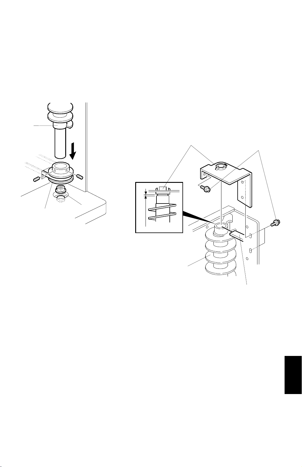
21 September 1998 HELICAL WHEELS REMOVAL
Installation
NOTE:
After installing the helical wheels, perform the helical wheels alignment
which is explained later.
Rear Helical Wheel
[B]
[C]
[D]
[E]
[A]
A821R528.WMF
[B]
[F]
A821R529.WMF
1. Place the bearing [A] on the notch on the bottom plate.
2. Set the helical wheel [B] into the pulley [C] then set the helical wheel on the
bearing [A].
3. Set the bracket with the bushing [D] on top of the helical wheel then install and
slightly tighten three screws [E].
4. Place a 0.4-mm thickness gauge [F] between the helical wheel [B] and the
bushing [D] on the bracket. While holding the bushing down to the helical
wheel, tighten the three screws [E].
Options
A821-49
Page 51

HELICAL WHEELS REMOVAL 21 September 1998
Front Helical Wheel
[D]
[K]
[C]
A821R530.WMF
[B]
[A]
[J]
[F]
[G]
[H][D]
A821R531.WMF
[I]
[E]
[L]
A821R532.WMF
1. Place the bearing [A] on the notch [B] on the bottom plate.
2. Set the pulley [C] on the bearing. The direction of the pulley should be as
shown in the illustration.
3. Set the helical wheel [D] in the pulley [C]. Leave the Allen screws [E] loosened.
4. Set the bracket with a bushing [F] on top of the helical wheels then install and
slightly tighten the four screws [G].
5. Place a 0.4-mm thickness gauge [H] between the helical wheel and the bushing
on the bracket. While holding the bushing down to the helical wheel [D], tighten
the four screws [G].
6. Hook tension springs [I and J] then tighten the screw [K].
7. Install the wheel sensor bracket [L].
A821-50
Page 52

21 September 1998 HELICAL WHEELS REMOVAL
Alignment of the 2 Helical Wheels
[B]
[A]
[C]
[C]
A821R533.WMF
[E]
[D]
Front
Rear
D = 1.7 0.5 mm
E = 22.5 0.5 mm
A821R534.WMF
1. Confirm all belts are set correctly.
2. Align all holes [A] at the middle of the helical wheels at the center of the bin
guide slots [B], as shown.
3. In this condition, tighten all Allen screws [C] on the helical wheel drive pulleys
(2 Allen screws on each drive pulley).
Options
4. Make sure that the gaps [D and E] between the base plates and the pulleys are
as shown in the illustration.
A821-51
Page 53

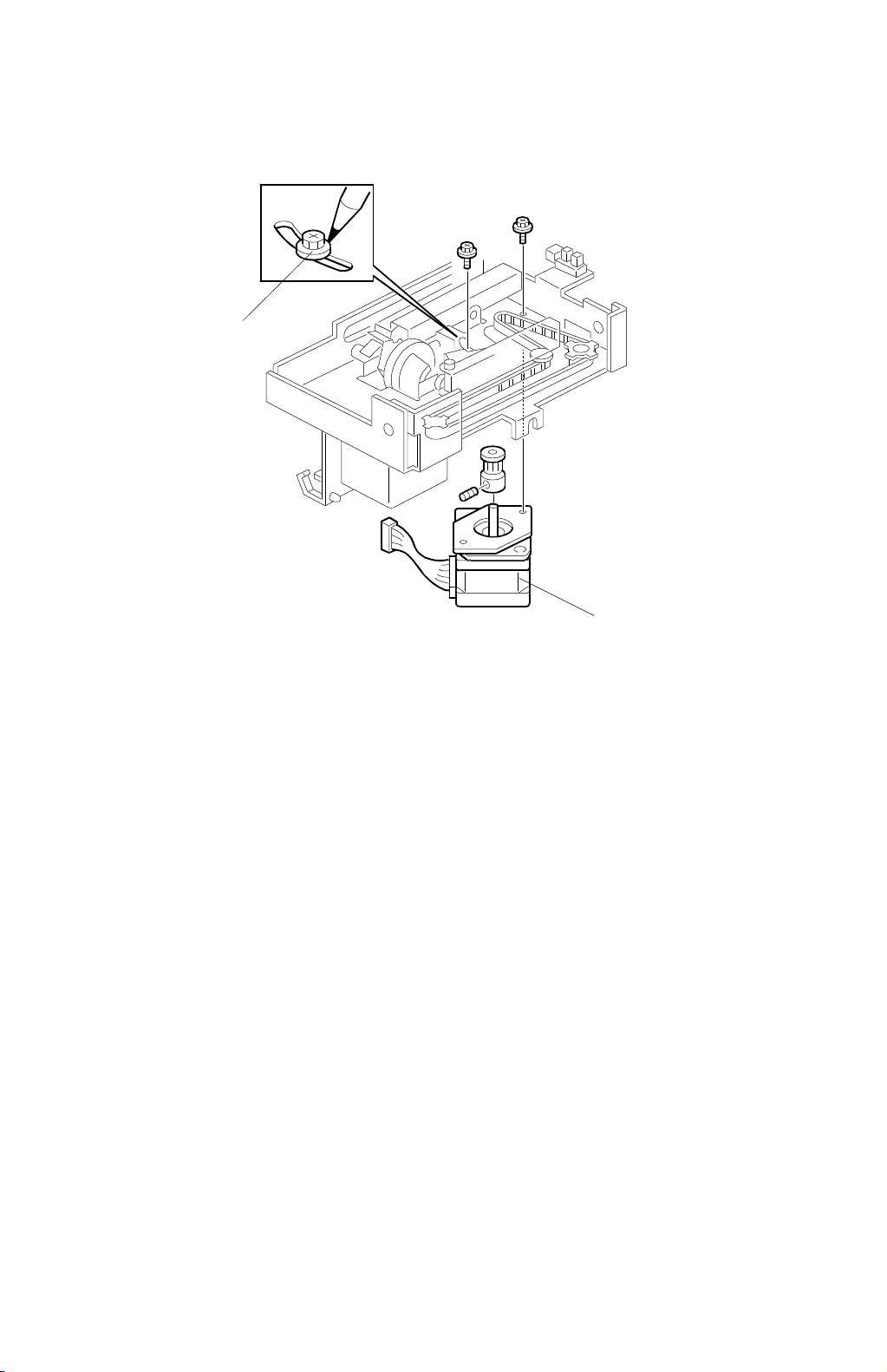
PUNCH UNIT REMOVAL 21 Sept ember 1998
4.14 PUNCH UNIT REMOVAL
[B]
[E]
[A]
A821R535.WMF
[A]
1. Open the front door.
2. Remove the knob [A] (1 screw).
3. Remove the shoulder screw [B].
4. Remove the rear cover.
5. Remove the punch unit [C] (4 screws and 3 connector).
NOTE:
To prevent the punch unit from being distorted, re-assemble the parts
as follows:
1) Push in the punch unit and install the shoulder screw [B].
2) Install the knob [A] (1 screw).
3) Temporarily secure the lower screw [D] for the rear.
4) Secure the upper screw [E] for the rear.
5) Set the connectors.
6) Leave the lower screw [D] un-tightened.
[C]
[D]
A821R536.WMF
A821-52
Page 54

1234567
POINT TO POINT DIAGRAM (SORTER STAPLER: A821)
A
A
Main Control
(PCB1)
[0]
[5]
[5]
[0]
[5]
[5]
[5]
[0]
[5]
[5]
[5]
[0]
[5]
[5]
[0]
[5]
[0]
[5]
[0]
[5]
[5]
[0]
[5]
[5]
[5]
[5]
[0]
[5]
[0]
[5]
[24]
[0]
[5]
[0]
[5]
[5]
CN170-1
-2
-3
CN170-4
-5
-6
CN170-8-9CN435-4
-10
-11
CN190-1
CN190-4
CN190-7
CN175-1
CN175-4
CN175-7
CN175-10
CN195-1
-10
-10
-11
-8
-9
-2
-3
-5
-6
-8
-9
-2
-3
-4
-5
-6
-7
-8
-9
-2
-3
-5
-6
-11
-12
CN315-3
CN335-3
CN430-4
CN405-6
CN405-3
CN600
-11
-10
-9
-8
-7
-6
-5
-4
-3
CN415-3
CN400-3
CN420-4
-3
-2
-1
CN310-3
-2
-1
CN330-3
-2
-1
CN425-4
-3
-2
-1
CN380-3
CN370-3
-5
-4
CN410-3
-2
-1
CN390-3
Punch Control Board
PCB3
CN620-1
CN620-6
-2
-1
CN620
-3
-2
-1
-2
-1
-2
-1
-3
-2
-1
-2
-1
-2
-1
-3
-2
-1
-2
-1
-2
-1
-2
-1
-2
-1
-2
-4
-6
-5
-7
-5
-4
PCB2
CN630
-1
-2
-3
S7
S8
S2
S1
S3
S12
S14
S13
S4
CN650-1
CN640
Grip HP Sensor
Grip Shift Motor
HP Sensor
Bin Jam Sensor
Entrance Sensor
Proof Exit Sensor
Bin Jam Sensor LED
Board
Stapler Unit HP Sensor
Stapler Unit Pull-out
Position Sensor
Paper Sensor
Bin HP Sensor
M10
-2
S15
-3
-1
-2
S16
-3
Punch Motor
Punch HP
Sensor
Punch Waste
Overflow
Sensor
B
C
D
E
F
G
[0]
CN105-1
-2
-3
-4
CN100-3
CN110
CN100-2
-1
-4
[0]
[24]
RXD/TXD
[24]
[24] 24V
SW
S/S Detection
Copier
B
Door Safety Switch
SW1
CN125-1
-2
-4
Exit Motor
C
Wheel Sensor
Bin Rear Plate Open
Sensor
D
Bin Rear Plate Close
Sensor
Jogger HP Sensor
E
Transport Motor
F
Stapler Unit Motor
G
Grip Shift Motor
M2
M1
M9
M7
S5
S10
S9
S6
CN395-3
-2
-1
CN360-3
-2
-1
CN365-3
-2
-1
CN385-3
-2
-1
CN265-12
-11
-10
CN220-7
CN235-7
-5
-6
-7
CN135-1
-2
-3
CN180-1
-2
-3
CN180-4
-5
-6
CN180-7
-8
-9
CN145-1
-2
-3
-9
-8
-5
-4
-3
-2
-1
-6
-4
-3
-2
-1
-6
-4
-3
-2
-1
-4
-5
-8
-9
-10
-11
-12
CN130-1
-2
-4
-5
-6
-7
CN155-1
-2
-4
-5
-6
-7
SW
[24] 24V
SW
[24] 24V
[24 0/24] : A
[24 0/24] : A
[24 0/24] : B
[24 0/24] : B
[0]
[5]
[5]
[0]
[5]
[5]
[0]
[5]
[5]
[0]
[5]
[5]
SW
[24] 24V
SW
[24] 24V
[0]
[0]
[0/5] Encoder
[0/5] Clock
[5/CW, 5/CCW ]
[5] ON
[0]
[5]
SW
[24] 24V
SW
[24] 24V
[24 0/24] : A
[24 0/24] : A
[24 0/24] : B
[24 0/24] : B
SW
[24] 24V
SW
[24] 24V
[24 0/24] : A
[24 0/24] : A
[24 0/24] : B
[24 0/24] : B
Bin Paper VR
Bin Jam VR
SW
24V
A : [5 0/5]
B : [5 0/5]
A : [5 0/5]
B : [5 0/5]
Punch Unit Set [5]
[24]
[24]
[5]
[5]
[5]
[0]
[5]
CN120-1
CN140-1
CN150-5
CN185-6
CN255-2
-2
-2
CN240-1
-4
-2
-1
-5
-4
-3
-2
-1
-1
CN260-2
-1
CN270-1
-2
-4
-5
-7
-8
-9
-10
-11
-12
M5
SOL1
-2
-4
-5
-7
-8
-9
-10
-11
-12
Bin Rear Plate Motor
Turn Gate Solenoid
M8
SW2
SW3
S11
Stapler Motor
Cartridge Set Switch
Staple End Switch
Stapler HP Sensor
H
I
-5
-4
-3
-2
-1
CN155-9
-10
-12
-13
-14
-15
CN160-1
CN120-4
[24] 24V
[24] 24V
[24 0/24] : A
[24 0/24] : A
[24 0/24] : B
[24 0/24] : B
[24] 24V
-2
[24] 24V
-4
[24 0/24] : A
-5
[24 0/24] : A
-6
[24 0/24] : B
-7
[24 0/24] : B
[24] 24V
-5
[24 0/24] : A
-6
[24 0/24] : A
-7
[24 0/24] : B
-8
[24 0/24] : B
-9
[24] 24V
SW
SW
SW
SW
SW
SW
SW
24V
[24]
SW
24V
[24]
- : [24]
- : [24]
+ : [24]
+ : [24]
Staple Unit Set [5]
CN225-7
-6
-4
Grip Motor
H
Bin Motor
I
Jogger Motor
M6
M3
M4
CN230-7
CN460-3
-11
-3
-2
-1
-6
-4
-3
-2
-1
CN440-6
-1
-5
-7
-9
SYMBOL TABLE
DC Line
Pulse Signal
Signal Direction
Active High
J
[ ]
Active Low
Voltage
J
123
45
67
Page 55

ELECTRICAL COMPONENT LAYOUT (A821)
2
1
33
32
31
30
29
28
27
26
25
24
23
22
3
4
5
6
17
18
19
20
21
A821S500.WMF
Symbol Name Index No. P to P
Motors
M1 Transport 32 E2
M2 Exit 26 C2
M3 Bin 19 H2
M4 Jogger 22 I2
M5 Bin Rear Plate 27 G6
7
8
9
10
11
12
13
14
15
16
M6 Grip 15 H2
M7 Grip Shift 17 G2
M8 Stapler 11 H6
M9 Stapler Unit 24 F2
M10 Punch 31 F7
Switches
SW1 Door Safety 6 B2
SW2 Cartridge Set 8 I6
SW3 Staple End 9 I6
Solenoids
SOL1 Turn Gate 1 H6
Sensors
S1 Entrance 5 C6
S2 Bin Jam 21 C6
S3 Proof Exit 4 C6
S4 Bin HP 23 E6
S5 Wheel Sensor 20 C2
S6 Jogger HP 25 E2
S7 Grip HP 16 B6
S8 Grip Shift Motor HP 14 B6
S9 Bin Rear Plate Close 28 D2
S10 Bin Rear Plate Open 29 D2
S11 Stapler HP 10 I6
S12 Stapler Unit HP 18 D6
S13 Paper 13 E6
S14 Stapler Unit Pull-out Position 12 E6
S15 Punch HP 33 G7
S16 Punch waste Overflow 7 G7
PCBs
PCB1 Main 30 A4
PCB2 Bin Jam Sensor LED 3 D6
PCB3 Punch Control 2 F6
 Loading...