

Page 1

20-BIN SORTER STAPLER
(Machine Code: A664)
Page 2
31 March 1997 SPECIFICATIONS
1. SPECIFICATIONS
Configuration: Console
Number of Bins: 20 + Proof Tray
Paper for Proof Tray:
Size Maximum: A3, 11" x 17"
Minimum: A6 lengthwise, 5
1/2
" x 8
1/2
"
2
Weight: 52 ~ 157 g/m
Capacity: Proof Tray - 250 sheets (80 g/m
,14 ~ 42 lb
2,
20 lb)
Paper for Bins: See the table below.
Sort Stack Staple
Maximum paper size A3, 11" x 17" A3, 11" x 17" A3, 11" x 17"
Minimum paper size Sideways:
1/2
A5, 8
Lengthwise:
1/2
A5, 5
Maximum paper weight 157 g/m
Minimum paper weight 52 g/m
Maximum capacity All sizes:
50 sheets/bin
Two-sided copies:
40 sheets/bin
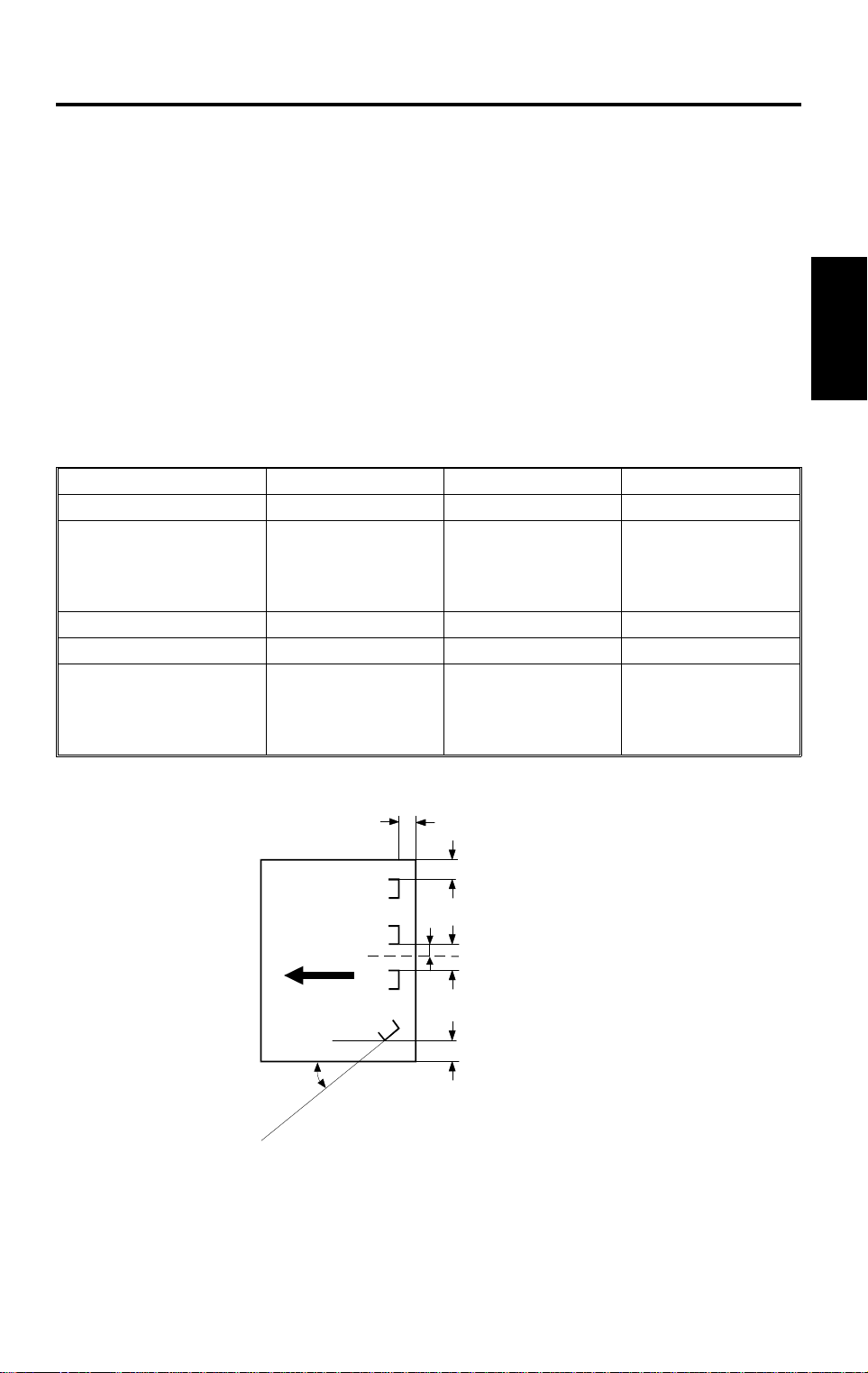
Stapling Positions:
" x 11"
1/2
" x 8
2
, 42 lb 157 g/m2, 42 lb 157 g/m2, 42 lb
2
, 14 lb 52 g/m2, 14 lb 52 g/m2, 14 lb
Sideways:
A5, 8
Lengthwise:
"
A5, 5
All sizes:
50 sheets/bin
Two-sided copies:
40 sheets/bin
a
1/2
" x 11"
1/2
" x 8
1/2
a = 6 ± 3 mm
"
1/2
B5, 8
All sizes:
50 sheets (80 g/m2)
" x 11"
b = 6 ± 3 mm
c
c = 6 ± 3 mm
d = 66 ± 3 mm
d
e
e = 132 ± 2 mm
θ = 45 ± 5°
Options
b
θ
A664V500.wmf
A664-1
Page 3

SPECIFICATIONS 31 March 1997
Staple Replenishment: Cartridge refill (5,000 pieces/cartridge)
Power Source: DC24 V (from copier)
Power Consumption: Average: less than 50 W (without punch)
Maximum:
In sort/stack mode: Less than 45 W
(without punch)
In staple mode: Less than 50 W
Dimensions:
566 x 583 x 978 mm
(W x D x H)
Weight: Approximately 48 kg
A664-2
Page 4

31 March 1997 COMPONENT LAYOUT
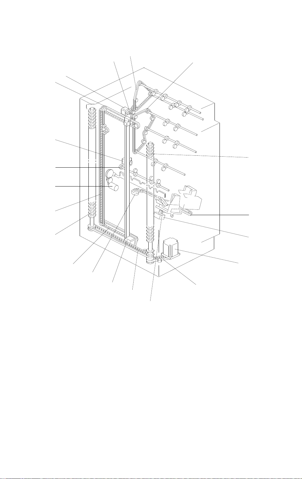
2. COMPONENT LAYOUT
2.1 MECHANICAL COMPONENT LAYOUT
1
2
3
12
Options
11
10
4
5
6
9
7
1. Proof Tray
2. Proof Exit Rollers
3. Proof Transport Rollers
4. Turn Gate
5. Sorter Transport Rollers
6. Sorter Exit Rollers
8
A664V501.wmf
7. Staple Unit
8. Grip Assembly
9. Helical Wheels
10. Jogger Plate
11. Bins
12. Upper Guide Plate
A664-3
Page 5
COMPONENT LAYOUT 31 March 1997
2.2 DRIVE LAYOUT
1
13
16
15
14
3
2
4
5
13
5
13
1. Main Motor
2. Main Drive Belt
3. Proof Drive Belt
4. Sorter Drive Belt
5. Helical Wheels
12
11
6
7
8
9
9
10
A664V502.wmf
9. Wheel Drive Belts
10. Grip Drive Belt
11. Jogger Motor
12. Staple Unit Drive Motor
13. Jogger Drive Belts
6. Staple Unit Drive Belt
7. Gripper Motor
8. Bin Drive Motor
14. Bin Rear Plate Drive Motor
15. Sorter Exit Drive Belt
16. Sorter Exit Motor
A664-4
Page 6

31 March 1997 ELECTRICAL COMPONENT DESCRIPTION
3. ELECTRICAL COMPONENT DESCRIPTION
Please refer to the electrical component layout on the reverse side of the
point-to-point diagram on waterproof paper.
Symbol Name Function Index No.
Motors
M1 Main Drives the pap er transport rolle rs . 1
M2
M3
M4
M5
M6
M7 Bin Rear Plate Dri ve Lowers and ra i ses the bin rear plate. 25
M8 Sorter Exit Delivers the paper into the bins. 28
Stapler Feeds the stapl es and drives the stapler
hammer.
Grip Drives the gri p assembly forward and
backward int o th e bi n t o gr i p the copies and
bring them to the st apling po sition.
Bin Drive Drives the bins upward and down w ar d by
rotating the three helical wheels.
Jogger Drives the jogger plate to jog the copies
against the front si de plate.
Stapler Unit Drive Drives the stapler unit in accordance with the
required staple position and angl e.
9
23
17
20
24
Options
Sensors
S1
S2 Proof Exit Detects paper ja m s at the proof tray exit. 4
S3 Entrance Detects paper jams at the entrance guides. 5
S4
S5
S6
S7
S8
S9
S10 Wheel Sensor Detects the bin position. 18
S11 Bin Home Posit i on Detects i f the bi ns are at the home po sition. 21
S12
S13
S14
Bin Jam (LED) Detects paper jams at the distribut i on section
and detects if there is paper in the bins.
Staple Hammer
Home Position
Stapler Unit
Pulled-out pos i tion
Paper Detects whethe r co pi es are under the
Stapler Unit Home
Position
Grip Home Position Detects if the grip assembly is in the home
Bin Jam (Photo Tr.) Detects paper jams at the distribution section
Jogger Home Posi t i on Detects if t he jo gger plate is at the home
Bin Rear Plate Ope n Detects if the bin rear plate is at the open
Bin Rear Plate Home
Position
Detects if the staple hammer is at th e home
position.
Detects if the stapler unit is at the pu l l ed- out
position.
hammer.
Detects if the stapler unit is at the home
position.
position.
and detects if there is paper in the bins.
position.
position.
Detects if the bin rear plate is at the home
(closed) po si t i on.
3
10
11
12
14
16
19
22
26
27
A664-5
Page 7

ELECTRICAL COMPONENT DESCRIPTION 31 March 1997
Symbol Name Function Index No.
Solenoids
SOL1
SOL2
SOL3
PCBs
PCB1 Main Contro l Controls all sorter stapler functions. 29
Switches
SW1
SW2
SW3 Staple End Detects staple end. 8
Turn Gate Opens and closes the turn gate to direct the
copies into ei t her the proof tray or the bin s.
Grip Opens and closes the grip arms to grip the
copies on the bins.
Grip Arm Positioning Moves the grip ass’y to the rear and front to
catch or release the paper to carry it to th e
stapler.
Door Safety Cuts the dc pow er when the front do or is
opened.
Cartridge Set Detects if the staple cartridge is installed or
not.
2
13
15
6
7
A664-6
Page 8
31 March 1997 BASIC OPERATION
4. BASIC OPERATION
4.1 NORMAL (PROOF MODE) AND SORT/STACK MODE
[C]
[B]
[A]
Options
A664D500.wmf
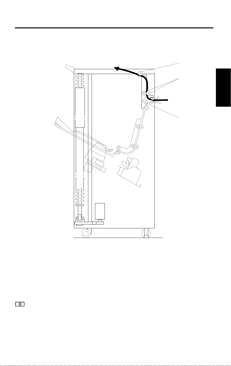
Copies exiting the copier pass through the entrance guide plates to the turn
gate section. The turn gate [A] will send copies either to the proof tray or to
the bins, depending on the mode.
– Normal (proof) mode (from the turn gate section to the proof tray) –
The turn gate solenoid energizes to turn the turn gate clockwise when the
!
key is pressed. The turn gate directs copies through the proof transport
section to the proof tray. The main motor turns counterclockwise to rotate the
vertical transport rollers [B] and proof exit roller [C].
A664-7
Page 9
BASIC OPERATION 31 March 1997
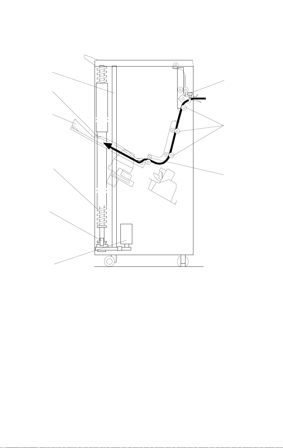
– Sort mode (from the turn gate section to the bins) –
[F]
[A]
[E]
[D]
[B]
[H]
[C]
[I]
[G]
A664D501.wmf
In this mode, the turn gate solenoid stays off to keep the turn gate [A] at the
upper position. The main motor turns clockwise to rotate the sorter transport
rollers [B] and the exit motor rotates the exit rollers [C].
The turn gate directs copies to the sorter bins through the sorter transport
section, then the first copy is delivered between the top bin [D] and the upper
guide plate [E]. The jogger plate [F] then jogs to square the copies each time.
Before the next copy reaches the sorter exit roller, the bin drive motor [G]
rotates and advances the bin one step (the helical wheels [H] rotate once).
When the cut out in the actuator reaches below the wheel sensor [I], the bin
drive motor turns off.
Bins advance each time copies are delivered.
A664-8
Page 10
31 March 1997 BASIC OPERATION
– Stack mode (from the turn gate section to the bins) –
[F]
[A]
[E]
[D]
[H]
[I]
[G]
Options
[B]
[C]
A664D501-2.wmf
As with sort mode, the turn gate solenoid stays off and the turn gate [A] stays
up when the
!
key is pressed. The main motor turns clockwise to rotate
the sorter transport rollers [B] and the exit motor rotates the exit rollers [C].
The turn gate directs copies to the sorter bins through the sorter transport
section, then the copies are delivered between the top bin [D] and the upper
guide plate [E]. The jogger plate [F] then jogs to square the copies each time.
All copies of the copy run are then fed to the first bin. When the final copy is
delivered, the wheel drive motor [G] turns and advances the bin one step (the
helical wheels [H] rotate once). When the cut out in the actuator reaches
below the wheel sensor [I], the bin drive motor turns off.
A664-9
Page 11
BASIC OPERATION 31 March 1997
4.2 STA PLE MODE
[Fig. 1]
A664D502.img
[Fig. 2]
A664D503.img
[Fig. 3]
A664D504.img
When the final set of copies is jogged [Fig. 1], the stapler unit staples the
stacked copies as follows:
The grip arms move inside the front side plate and catch the paper.
The bin rear plate is turned so as to be flat with the sorter bin.
The grip assembly brings the copies down underneath the stapler [Fig. 2].
The staple unit changes position (the position varies depending on the copy
size and staple mode) and the stapler staples the copies [Fig. 3].
A664-10
Page 12
31 March 1997 BASIC OPERATION
[Fig. 4]
A664D505.img
Options
[Fig. 5]
A664D506.img
The grip assembly brings the stapled copies back to the bin and the bin rear
plate returns to the original position.
The grip assembly releases the copies and returns to outside the front side
plate so as not to disturb the bin movement [Fig. 4].
The bin advances one step [Fig. 5].
When the final set of copies is stapled, the stapler unit is returned to the
home position.
There are two staple modes.
1) Automatic stapling:
In ADF mode, when staple mode is selected before pressing the
!
key,
copies will be delivered to each bin and stapled automatically.
2) Manual stapling:
In sort mode, after copies are sorted in the bins, the copies will be stapled
when the manual staple key is pressed and the staple position is
selected. In stack mode, manual stapling is impossible.
A664-11
Page 13
TURN GATE 31 March 1997
5. TURN GATE
[A]
[I]
[D]
[G]
[C]
[B]
A664D507.wmf
[C]
[H]
[E]
[F]
A664D508.wmf
The turn gate [A] sends copies to the proof tray or the sorter bins depending
on the mode. In the proof mode, the turn gate solenoid [B] turns on and the
main motor [C] turns clockwise when the
!
key is pressed.
The turn gate [A], directs copies upward through the proof transport section
to the proof tray. In this mode, main motor drive is transmitted by both the
proof drive belt [D] and sorter drive belt [E]. However, the one-way clutch in
each sorter transport roller drive gear [F] does not transmit the drive to the
sorter transport rollers.
In the sort, stack, and staple modes, the turn gate solenoid stays off to direct
copies downward to the sorter transport section. When the
!
key is
pressed, the main motor [C] turns counterclockwise.
In this mode, main motor drive is not transmitted to the proof drive belt [D]
because of the one-way clutch in the pulley [G]. The entrance [H] and the
proof exit [I] sensors check for paper jams.
A664-12
Page 14
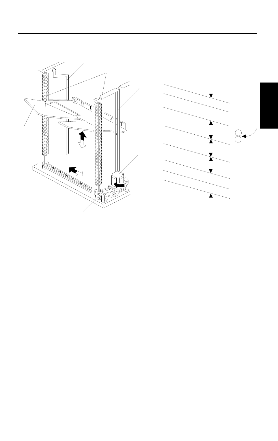
31 March 1997 BIN DRIVE MECHANISM
6. BIN DRIVE MECHANISM
[D]
[F]
[C]
[B]
A664D509.wmf
[E]
[A]
15
Options
30
[H]
45
[G]
40
40
15
15
A664D510.wmf
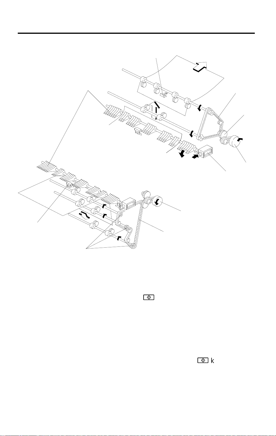
The bin drive mechanism moves the bins up and down to receive copies. The
main components in this mechanism are the bin drive motor [A], the two
helical wheels [B], the wheel sensor [C], and the bins themselves [D]. There
are four pins on each bin. Two of them fit in the slots in the helical wheels.
Another pin fits into the slot [E] in the front side frame, and the last pin fits in
the guide rail [F]. The pins slide up and down in these slots.
Two timing belts transmit drive from the bin drive motor to the helical wheels.
When the motor rotates clockwise, the bins lift (black arrow) and when it
rotates counterclockwise, the bins lower (white arrow). The wheel sensor
actuator on the front helical wheel has a slot which detects when the helical
wheel has rotated 360 degrees.
When the bins are advanced, the helical wheels rotate once (360 degrees)
for each step.
As the pitch of the spiral on the helical wheel is greater when bins are at the
staple and paper exit area than when bins are elsewhere, the amount of bin
shift is greater when bins are at the staple and paper exit area. This leaves
enough space to staple [G] and stack paper [H] and reduces the total
machine height.
A664-13
Page 15
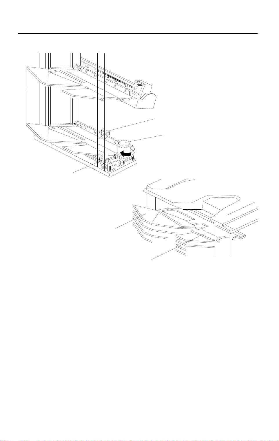
BIN HOME POSITION 31 March 1997
7. BIN HOME POSITION
[A]
[E]
[B]
A664D511.wmf
[D]
[C]
A664D512.wmf
The bin home position sensor [A] and the wheel sensor [B] ensure that the
sorter exit roller is between the upper guide plate [C] and the 1st bin [D] when
all the bins are at the home position.
When the main switch is turned on, the bin lift motor [E] lowers the bins (turns
counterclockwise) until the bottom bin actuates the bin home position sensor.
Then, the bin lift motor raises the bins (turns clockwise) until the wheel
sensor activates. At this point, the bins are in the home position.
A664-14
Page 16
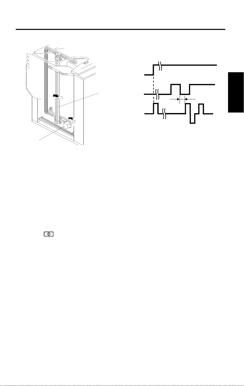
31 March 1997 JOGGER
8. JOGGER
ON
Copier Main
Motor
[B]
Bin Jam
Sensor
Jogger
Motor
300 ms
A664D514.wmf
[A]
A664D513.wmf
•
NOTE:
The bin jam detector contains two LED/phototransistor pairs.
•
To detect jams, light from an LED above the bins passes through
the slots in the bins to a phototransistor below the bins. If the light
path is blocked at the wrong time, a jam is detected.
•
To detect paper in the bins, light from another LED above the bins
passes through the circular holes in the bins to another
phototransistor below the bins. If the light path is blocked, the
machine determines that there is paper in the bins.
When the
!
key is pressed in the sort, staple, and stack modes, the copier
sends the paper size information to the sorter stapler. In accordance with this
data, the jogger motor [A] drives the jogger plate [B] from the jogger home
position to a point 10 mm wider than the selected paper.
Options
300 ms after the trailing edge of the copy passes underneath the bin jam
sensor (jam detection part), the jogger motor rotates forward and in reverse.
This makes the jogger plate push all the copies against the front side plate to
square the sheets. When the jogger plate pushes the paper, the plate shifts
to a position 5 mm wider than the paper size when the bins lift, and it shifts to
a position 1 mm narrower than the paper size when the bins lower.
The jogger plate then returns to 10 mm away from the selected paper size for
the next copy.
When the bin jam sensor (paper detector part) detects that all copies have
been removed from the bins after jogging is finished, the jogger plate returns
to its home position.
A664-15
Page 17

JOGGER 31 March 1997
[C]
[B]
Fig. 1
[D]
[A]
[E]
[C]
A664D515.wmf
Normally all rollers in the sorter stapler transport the paper at a speed of 360
mm/s. To have enough paper jogging time, the sorter exit motor [A] rotation
speed changes as follows to transport the paper quickly and to stack the
paper smoothly into the bins.
•
360 mm/s: When the sorter exit roller [B] catches the leading edge of the
paper
•
1,000 mm/s: After the bin jam sensor [C] detects the leading edge of the
paper
•
600 mm/s: When releasing the trailing edge of the paper
The transport roller [D] is driven at a speed of 360 mm/s constantly. However,
when the sorter exit roller [B] rotates quickly, the transport rollers also rotate
quickly with the pulled paper because of the one-way clutch in the drive gear
[E].
– Jogger Off Conditions –
1. Under the following conditions, the jogger plate does not jog after copies
are delivered to the bins.
•
If paper is loaded in a bin by hand while the sort/stack or staple mode
is selected.
•
If the selected paper size does not match the stapling specifications.
•
If copy of smaller width is delivered to the bins later in the "Mixed
sizes" mode.
2. If paper is in a bin before the main switch is turned on, the sort/stack
mode is disabled when the sort key is touched.
A664-16
Page 18

31 March 1997 BIN REAR PLATE DRIVE
9. BIN REAR PLATE DRIVE
[A]
[A]
[F]
[J]
[F]
[G]
[E]
[I]
[G]
[C]
Options
[B]
[D]
[H]
[I]
A664D516.wmf
The bin rear plates [A] basically stand up as shown (top diagram). They are
lowered only during stapling as shown (bottom diagram).
In staple mode, when all copies have been jogged by the jogger plate, the bin
rear plate drive motor [B] rotates gear [C]. Gear [C] drives the piston rod [D]
to push the lever [E] down.
The holder [F] engaging the pin [G] on the bin rear plate lowers with the lever
[E]. Thus, the bin rear plate becomes flat so as not to interfere with the copies
being brought to the stapling position by the grip assembly.
While the rear plate is down (during stapling), the bin rear plate open sensor
[H] is interrupted by the actuator [I] (bottom diagram). After stapling is
completed and stapled paper is returned to the bin, gear [C] rotates 180
degrees and the bin rear plate returns to its home position.
When the bin rear plates are in the home position, the bin rear plate HP
sensor [J] is interrupted by the actuator [I] (top diagram). Also, the holder [F]
is vertical again, and the pins [G] on the bins can move up or down through
the holder as the bins are moved up or down.
A664-17
Page 19

GRIP ASSEMBLY 31 March 1997
10. GRIP ASSEMBLY
[B]
[A]
[C]
A664D517.wmf
Staple Unit Drive
Motor
Grip Arm Positioning
Solenoid
Grip Solenoid
Bin Rear Plate
Drive Motor
+
❶
OFF
+
+
❷
OFF
OFF
+
OFF
A664D518.wmf
The grip assembly works as follows:
❶ When the stapler unit reaches the stapling position, the grip arm
positioning solenoid [A] activates and the plunger is pulled in to move the
grip arms [B] towards the rear of the machine. This is to access the
paper on the bin.
The grip arm positioning solenoid has a strong magnet inside; the plunger
stays in this condition until the solenoid is energized by an opposite
charge.
The inset at the upper right of the illustration shows the mechanical
linkage as seen from the top.
❷ The grip solenoid [C] activates to close the grip arms and the grip arms
catch the papers.
For this solenoid also, the plunger keeps the grip arms closed until the
solenoid is energized by an opposite charge.
A664-18
Page 20

31 March 1997 GRIP ASSEMBLY
[A]
[F]
[D]
Bin Rear Plate
Drive Motor
Grip Motor
Staple Motor
Grip Solenoid
Grip Arm Positioning
Solenoid
A664D519.wmf
[C]
[B]
[E]
Options
+
+
❸
–
+
–
OFF
OFF
❹
OFF
❺
OFF
❻
OFF
–
A664D520.wmf
❸ After the bin rear plate drive motor lowers the bin rear plate, the grip
motor [A] turns clockwise (white arrow) until the gripper [B] carries the
paper to the stapling position.
❹ After stapling is finished, the grip motor turns counterclockwise to move
the stapled copies held in the grip arms back to the bin.
❺ When the grip solenoid [C] activates in reverse, the return spring [D]
opens the grip arms to release the copy into the bin.
❻ The grip arm positioning solenoid [E] activates to return the grip arms to
the home position to prepare for the next stapling cycle.
The grip home position sensor [F] is actuated while the gripper is in the home
(grip) position. The sorter stapler main control board sends the appropriate
pulses to the grip motor (a stepper motor) [A] to reach the grip position and
stapling position.
Vertical stapling positions can be adjusted by changing the number of
stepper motor pulses from the home position (see the SP mode table in the
copier service manual).
A664-19
Page 21

STAPLER UNIT 31 March 1997
11. STAPLER UNIT
11.1 STAPLER UNIT DRIVE MECHANISM
[B]
[A]
A664D529.wmf
The stapler unit moves from the home position (top slant position) towards
the rear of the machine in order to change the stapling position. The stapler
unit HP sensor [A] activates when the stapler unit is in the home position.
In Top Slant mode, the stapler stays at the home position.
In "Top" ("Bottom") single staple mode, the stapler unit moves to the front
(rear) single staple position and stays there until all stapling is completed. It
then returns to the home position.
In "2 Staples" mode or "Bottom" single staple mode, the stapling positions
depend on the paper size. The stapler unit drive motor [B] is a stepper motor,
and the stapling position is reached by counting the steps from the home
position. During stapling in the "2 Staples" mode, the stapler unit goes back
and forth to staple the two positions.
Horizontal stapling positions can be adjusted by changing the number of
stepper motor pulses from the home position (see the SP mode table in the
copier service manual).
A664-20
Page 22

31 March 1997 STAPLER UNI T
11.2 STAPLER
[C]
[B]
[D]
[E]
[A]
A664D521.wmf
[F]
Options
[J]
[G]
A664D522.wmf
[H]
The stapler motor [A] drives the staple sheet drive belt. The staple sheets are
fed under the hammer [B].
The stapler motor drives the staple hammer via gears [C] and two eccentric
cams [D].
When the aligned copies are brought to the stapling position by the grip, the
stapler motor starts rotating to staple the copies. When the cams complete
one rotation, the staple hammer home position sensor [E] is de-actuated. The
stapler motor then stops.
When the paper sensor [F] in the grip assembly does not detect copies under
the hammer, the stapler motor does not rotate.
The staple end sensor [G] detects staple end conditions. The cartridge set
sensor [H] detects when the staple cartridge is not installed.
The staple cartridge has a clinch area [J], in which the jammed staples are
left. Operators can remove the jammed staples from the cartridge.
A664-21
Page 23

STAPLER UNIT 31 March 1997
– Conditions in which Stapling is Disabled –
1. Under the following conditions, the staple mode is disabled when the
staple key on the operation panel is pressed.
•
If there is paper in a bin before the main switch is turned on.
•
If the selected paper size does not match the stapling specifications.
•
If the paper is fed from the by-pass feed table.
2. Under the following conditions, the staple mode is canceled.
•
If paper is loaded in a bin by hand while the staple mode is selected.
•
If only one sheet is delivered to the bin.
•
If the stack, slip sheet, or interrupt modes are selected.
3. Under the following conditions, the manual stapling mode in sort mode
cannot be selected.
•
If paper is loaded in a bin by hand while the sort mode is selected.
•
If the paper size in the bin does not match the stapling specifications.
•
If only one sheet is delivered to the bin.
•
If a smaller width of paper is delivered on the bin later in "Mixed Sizes"
mode.
•
If copies already stapled are left in the bin.
A664-22
Page 24

31 March 1997 STAPLER UNI T
11.3 STAPLER UNIT PULL-OUT MECHANISM
[C]
[B]
[D]
[A]
Options
A664D525.wmf
For easy staple cartridge replenishment, the stapler unit can be pulled out to
the front. When pulling out the R3 release grip [A] , the stopper is released
and the staple unit can be pulled out (to the "staple unit pulled-out" position).
At this position, the stopper arm [B] locks the stapler unit by dropping the arm
to the edge of bracket [C].
When the stapler unit is not pushed in completely (the staple unit is between
the stapler unit home position and stapler unit pulled-out position [D]), a
message is displayed advising the user to put the staple unit in the home
position.
A664-23
Page 25

JAM DETECTION 31 March 1997
12. JAM DETECTION
Copier Exit
Sensor
Entrance
Sensor
Proof Exit
Sensor
Bin Jam
Sensor
(700 ms)
280 pls
ON Check
*This is the jam dete ct i on t i m i ng f o r the 1st bin.
Timing depends on the bins used.
1 pulse ¢ 3.61 ms
A664D526.wmf
– Sorter Jams –
The sorter stapler main control board detects jams when the following
conditions are detected. In these cases, a jam signal is sent to the copier,
then the copier stops the paper feed and indicates a sorter misfeed.
– Normal (Proof) mode –
J1: The entrance sensor has not turned on 700 ms after the copier exit
sensor turns on.
J2: The entrance sensor stays on for more than a certain number of pulses
(for example, 280 pulses for A4 sideways).
J3: The proof exit sensor has not turned on 300 pulses after the entrance
sensor turns on.
J4: The proof exit sensor stays on for more than a certain number of pulses
(for example, 280 pulses for A4 sideways).
– In Sort/Stack or Staple Mode –
J1 and J2: Same as Normal mode.
J5: The bin jam sensor has not turned on for 600 pulses after the entrance
sensor turns on.
J6: The bin jam sensor stays on for more than a certain number of pulses (for
example, 280 pulses for A4 sideways).
J7: The bin jam sensor is still on when the bin drive motor turns on.
A664-24
Page 26

31 March 1997 TIMING CHA R TS
13. TIMING CHARTS
13.1 SORTER/STAPLER TIMING CHART (PROOF MODE)
Timing ChartSignal
Copier Main
Motor ON
Proof mode
Paper size
data
Exit signal
Sorter busy
S/S exit
signal
S/S main
motor ON
Entrance Sensor
Proof Exit Sensor
Options
A664D527.wmf
A664-25
Page 27

TIMING CHARTS 31 March 1997
13.2 SORTER/STAPLER TIMING CHART (STAPLE MODE)
Signal
Copier Main
Motor ON
Stapling
Proof mode
Staple mode
Exit signal
Paper size data
Bin data
Sorter busy
S/S Exit
signal
Proof count
Job complete
Entrance sensor
Bin jam sensor
Timing Chart
Sorter exit motor
Sorter main motor
Jogger motor
Stapler unit
drive motor
Grip motor
Grip HP sensor
Grip positio ni ng
solenoid
Grip solenoid
Stapler motor
Bin rear plate
drive motor
Bin drive motor
NOTE:
1) Jogger motor on time depends on the paper size.
2) Staple unit drive motor on time depends on the paper size.
NOTE 1
300 ms
NOTE 1
NOTE 2
NOTE 3
A664D528.wmf
3) Bin drive motor on time depends on the number of copy sets.
A664-26
Page 28

31 March 1997 SERVICE TABLES (MAIN CONTROL BOARD)
14. SERVICE TABLES (MAIN CONTROL
BOARD)
14.1 DIP SWITCHES
Dip Switch 100
Function 1234
Standard setting 0 0 — —
Raises all bins to the top position 1000
Free run 0100
Dip Switch 101
Dip Switch 102
Adjustment Value 1234
Standard Position 0 0 0 —
0.5 mm 1 0 0 0/1
1.0 mm 0 1 0 0/1
1.5 mm 1 1 0 0/1
2.0 mm 0 0 1 0/1
2.5 mm 1 0 1 0/1
3.0 mm 0 1 1 0/1
3.5 mm 1 1 1 0/1
+ direction (See the illustration below.) — — — 0
– direction (See the illustration below.) — — — 1
Vertical Staple Position Adjustment
Horizontal Staple Position Adjustment
0: OFF 1: ON
Options
NOTE:
The adjustment value and the combination of the dip switch positions
are exactly the same for Dip Switch 101 and Dip Switch 102.
Dip Switch 101
Feed
direction
- direction
↑
+ direction
↓
Dip Switch 102
- direction
A664M500.wmf
Feed
direction
+ direction
A664-27
Page 29

SERVICE TABLES (MAIN CONTROL BOARD) 31 March 1997
14.2 TEST PO I N TS
Number Function
TP100 GND
TP101 + 5 V
14.3 FUSES
FUSES Rated Current and Voltag e
FUSE100 250 V T5A
A664-28
Page 30

31 March 1997 REPLACEMENT AND ADJUSTMENT
15. REPLACEMENT AND ADJUSTMENT
15.1 EXTERIOR COVER REMOVAL
– Front –
Remove the covers in the following order.
[A]
[D]
Options
[B]
[C]
A664R500.wmf
[F]
[E]
A664R501.wmf
1. Remove the proof tray [A] (4 screws).
2. Open the front door.
3. Remove the front inner cover [B] (3 screws).
4. Remove the front wheel cover [C] (3 screws).
5. Remove the four screws that hold the front left cover [D] and remove the
front left cover by shifting the cover up to release the two hooks.
6. Remove the front lower cover [E] (3 screws).
7. Remove the front door [F] (2 hinge pins).
A664-29
Page 31

REPLACEMENT AND ADJUSTMENT 31 March 1997
– Rear –
[A]
1. Remove the rear cover [A] (6 screws).
2. Remove the bottom plate [B] (2 screws and 1 hook).
[B]
A664R502.wmf
A664-30
Page 32

31 March 1997 REPLACEMENT AND ADJUSTMENT
15.2 STAPLER REMOVAL AND REINSTALLATION
Options
[A]
[B]
[F]
A664R503.wmf
[E]
A664R504.wmf
[C]
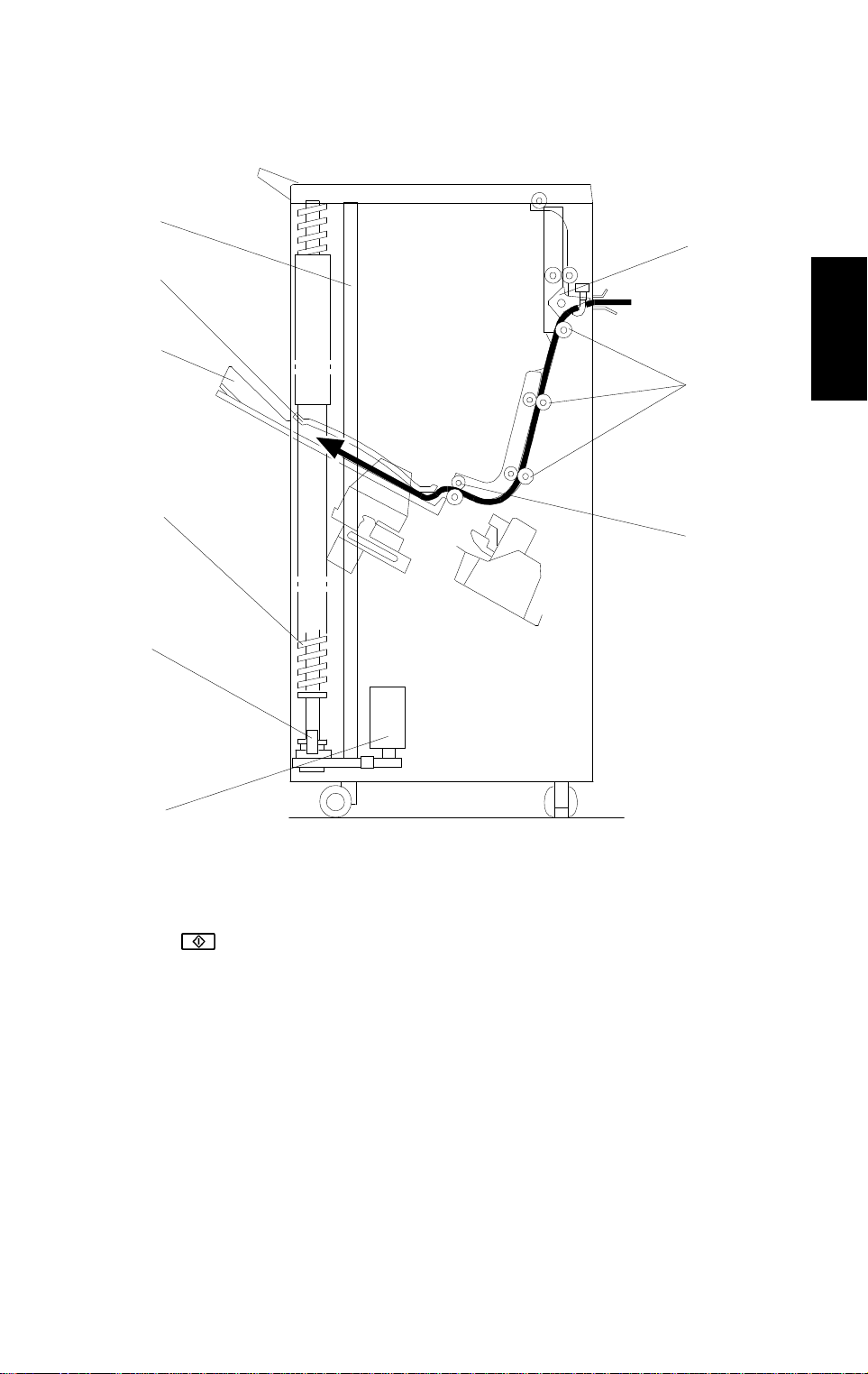
1. Return the stapler unit [A] to the home position by pulling out the stapler
unit.
2. Pull out the R3 release lever [B] and pull out the stapler unit.
[D]
3. Remove the harness cover [C].
4. Remove the stapler unit [D] (1 connector and 1 screw).
NOTE:
When re-assembling, hook the cut-out [E] over the shoulder screw
[F].
A664-31
Page 33

REPLACEMENT AND ADJUSTMENT 31 March 1997
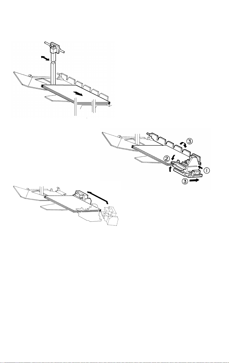
15.3 JOGGER PLATE REMOVAL AND INSTALLATION
[A]
[B]
[C]
[E]
A664R505.wmf
[D]
A664R506.wmf
– Removal –
1. Remove the proof tray. (Refer to Exterior Cover Removal.)
2. Release the spring [A] of the upper jogger holder [B], then pull out the
jogger plate [C].
– Installation –
1. Insert the jogger plate through the upper holder [B].
2. Push down the jogger plate towards the lower holder [D].
3. Set the jogger plate in the lower holder [D].
4. Hook the spring [A] of the upper jogger holder onto the stopper [E].
A664-32
Page 34

31 March 1997 REPLACEMENT AND ADJUSTMENT
15.4 BINS
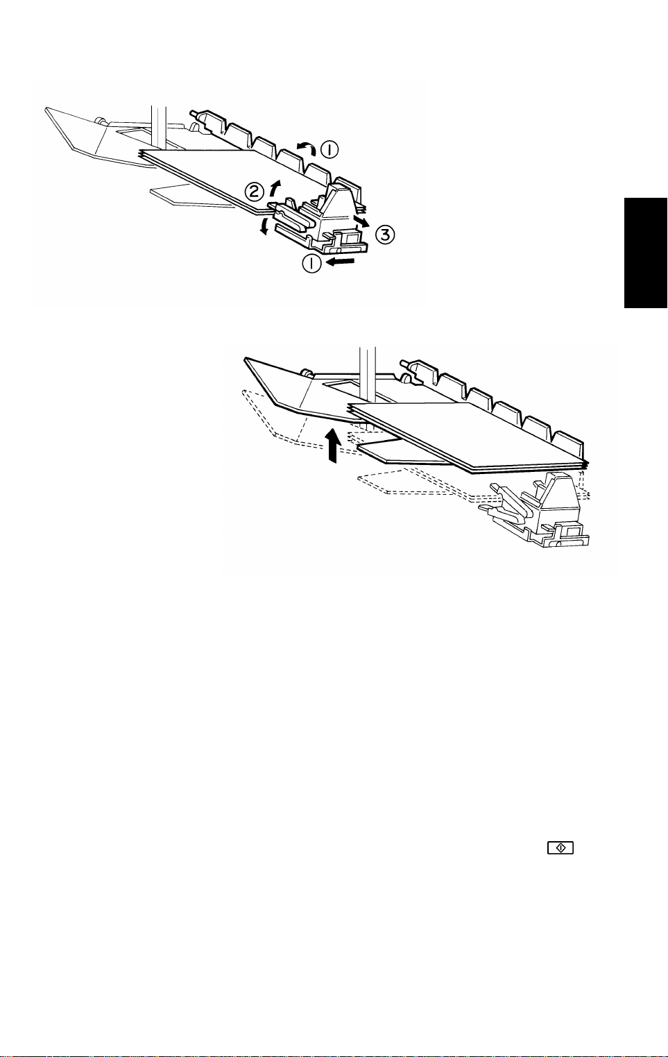
– Removal –
[A]
[D]
Options
A664R507.wmf
[C]
[B]
A664R508.wmf
1. Remove the rear cover.
2. Raise all bins to the highest position by turning on DIP SW100-1 on the
sorter main PCB, then turn off the main switch of the copier.
3. Remove the jogger plate (refer to Jogger Plate Removal), then move the
upper jogger holder [A] to the front.
4. Remove the rear cover, then remove the bottom plate to access the drive
belt. (Refer to Exterior Cover Removal.)
5. Manually rotate the helical wheel drive belt [B] and move up the top guide
[C] until the three guide pins [D] reach the top of the helical wheel as
shown.
A664-33
Page 35

REPLACEMENT AND ADJUSTMENT 31 March 1997
[B]
[D]
[C]
A664R509.wmf
[H]
[F]
[A]
[E]
[G]
A664R510.wmf
6. Remove the top guide by releasing the pins [A] and [B] from cut-outs [C]
and [D] at the end of the bin guide slots. Then remove the pins [E] and [F]
from cut-outs [G] and [H].
7. Move up the next bin to the top position by manually rotating the helical
wheel drive belt and remove it as in the top guide removal procedure
(steps 5 and 6).
8. Remove the other nineteen bins by repeating step 7.
A664-34
Page 36

31 March 1997 REPLACEMENT AND ADJUSTMENT
– Installation –
[C]
[A]
[F]
[D]
[J]
[B]
[H]
[E]
[E]
Options
[G]
A664R511.wmf
[I]
A664R512.wmf
1. While holding the bin rear plate [A] straight, insert rear right guide pin [B]
into the slot [C], then lower the rear guide pin to the corner [D].
2. While still holding the bin rear plate straight, insert the front right guide pin
[E] into guide slot [F].
3. Insert the other guide pins [G] and [H] into the slots [I] and [J].
A664-35
Page 37

REPLACEMENT AND ADJUSTMENT 31 March 1997
[A]
A664R513.wmf
4. Manually rotate the helical wheel drive belt [A] and lower the bin.
NOTE:
Before installing the next bin, rotate the helical wheels only once.
Otherwise, the distance between the guide pins [B] will become
uneven and the bins will tilt.
[B]
Good
No good
5. Install all bins and the top cover by repeating steps 1 to 4.
6. Re-install the jogger plate and all covers.
A664-36
A664R514.wmf
Page 38

31 March 1997 REPLACEMENT AND ADJUSTMENT
15.5 MAIN MOTOR REMOVAL
Options
[A]
[B]
A664R515.wmf
1. Remove the rear cover (4 screws).
2. Disconnect the connector [A].
3. Remove the main motor bracket [B] (4 screws) with the main motor.
A664-37
Page 39

REPLACEMENT AND ADJUSTMENT 31 March 1997
15.6 GRIP ASSEMBLY REMOVAL, AND GRIP SOLENOID,
AND GRIP POSITIONING SOLENOID ADJUSTMENT
[A]
[C]
A664R517.wmf
[B]
[B]
[D]
[C]
[D]
– Grip assembly removal –
A664R518.wmf
1. Open the front cover then remove the front inner cover. (Refer to Exterior
Cover Removal.)
2. Remove the grip assembly [A] (4 connectors, 3 screws).
3. Replace the grip solenoid [B] and the grip arm positioning solenoid [C].
Note:
Mark the original positions of the plungers first (see below).
– Grip solenoid [B] and the grip arm positioning solenoid [C]
adjustments –
It is impossible to perform the fine positioning adjustments for these
solenoids because the magnets in both solenoids pull the plunger very
strongly.
So, mark the original position of the solenoids before removing the solenoid.
Then place the solenoid at the original position by referring to the mark you
made [D] and tighten the screws (4 screws for the grip solenoid and 3 screws
for the grip arm positioning solenoid).
A664-38
Page 40

31 March 1997 REPLACEMENT AND ADJUSTMENT
15.7 MAIN CONTROL BOARD REPLACEMENT
[A]
Options
A664R520.wmf
1. Remove the rear cover (refer to Exterior Cover Removal), then
disconnect all connectors (15 connectors and 1 fiber optics connector).
2. Remove the main control board [A] (6 studs).
3. Install the new main control board and connect all connectors.
4. Position DIP SW 100, 101 and 102 as on the original main control board
(DIP SW 101 and 102 are for stapling position adjustment and DIP SW
100 is for SP mode).
5. Turn on the copier main switch then check the stapling position. If it is
incorrect, adjust the stapling position. (Refer to the Stapling Position
Adjustment.)
A664-39
Page 41

REPLACEMENT AND ADJUSTMENT 31 March 1997
15.8 GRIP MOTOR REMOVAL
[A]
1. Remove the grip assembly.
2. Remove the grip motor [A] (4 screws and 2 Allen screws).
A664R519.wmf
A664-40
Page 42

31 March 1997 REPLACEMENT AND ADJUSTMENT
15.9 HELICAL WHEELS
– Removal –
Before removing the helical wheels, remove all bins and all exterior covers.
(Refer to Exterior Cover and Bin Removal.)
– Front Helical Wheel –
[A]
[F]
Options
[C]
A664R524.wmf
[C]
[D]
[E]
[D]
A664R526.wmf
1. Remove the bracket [A] (4 screws).
2. Remove the wheel sensor bracket [B] (1 screw).
3. Unhook the two springs [C].
[B]
A664R525.wmf
4. Loosen the two Allen screws [D].
5. While holding the pulley [E] to keep it in position, remove the helical
wheel [F].
A664-41
Page 43

REPLACEMENT AND ADJUSTMENT 31 March 1997
– Rear Long Helical Wheel –
[A]
[D]
[D]
[C]
[B]
A664R527.wmf
A664R528.wmf
1. Remove the bracket [A] (3 screws).
2. Loosen the two Allen screws [B] on the drive pulley.
3. While holding the pulley [C] to keep it in position, remove the helical
wheel [D].
A664-42
Page 44

31 March 1997 REPLACEMENT AND ADJUSTMENT
– Installation –
NOTE:
After installing the helical wheels, perform the helical wheel
alignment, which is explained later.
– Rear Long Helical Wheel –
[B]
[C]
A664R533.wmf
[A]
[D]
Options
[E]
0.4 mm
[B]
[F]
A664R534.wmf
1. Place the bearing [A] over the stud on the bottom plate.
2. Insert the helical wheel [B] into the pulley [C], then place the helical wheel
on the bearing [A].
3. Place the bracket with the bushing [D] on top of the helical wheel, then
install and slightly tighten three screws [E].
4. Place a 0.4 mm thickness gauge [F] between the helical wheel [B] and
the bushing [D] on the bracket. While holding the bushing down on the
helical wheel, tighten the three screws [E].
A664-43
Page 45

REPLACEMENT AND ADJUSTMENT 31 March 1997
– Front Helical Wheel –
[F]
[J]
[K]
[C]
[G]
[E]
[B]
[N]
[D]
[I]
[H]
[O]
[A]
A664R535.wmf
[P]
[H]
[K]
[L]
A664R536.wmf
[M]
[I]
A664R537.wmf
1. Place the bearing [A] over the stud [B] on the bottom plate then thread
timing belt-918XL [C] and timing belt-300XL [D] around the pulley.
2. Place the pulley [E] on the bearing. The direction of the pulley should be
as shown in the illustration.
3. Feed the helical wheel through the wheel sensor actuator [F]. Leave the
Allen screw [G] loosened.
4. Place the helical wheel [H] in the pulley [E]. Leave the Allen screws [I]
loosened.
5. Place the bracket with a bushing [J] on top of the helical wheel, then
install and slightly tighten the four screws [K].
6. Place a 0.4 mm thickness gauge [L] between the helical wheel and the
bushing on the bracket. While holding the bushing down on the helical
wheel [H], tighten the four screws [K].
7. Hook tension springs [M] and [N] then tighten the screw [O].
8. Install the wheel sensor bracket [P].
A664-44
Page 46

31 March 1997 REPLACEMENT AND ADJUSTMENT
– Alignment of the 2 Helical Wheels –
[C]
[B]
[A]
[C]
A664R538.wmf
Options
[D]
[E]
A664R539.img
[G]
[F]
Front Rear
A664R540.wmf
G = 22.5 ± 0.5 mm
F = 1.7 ± 0.5 mm
1. Check that all belts are set correctly.
2. Align all screw holes [A] at the middle of the helical wheels at the center
of the bin guide slots [B], as shown.
3. In this condition, tighten all Allen screws [C] in the helical wheel drive
pulleys (2 Allen screws on each drive pulley).
4. In this condition, place the cut out [D] on the wheel sensor actuator under
the wheel sensor [E] then tighten the Allen screw on the wheel sensor
actuator.
5. Make sure that the gaps [F and G] between the base plates and the
pulleys are as shown in the illustration.
A664-45
Page 47

INSTALLATION 31 March 1997
11.5 20-BIN SORTER STAPLER (A664) ACCESSORY CHECK
Check the accessories against the following list:
Description Q’ty
1. Front Connection Bracket................................................. 1
2. Rear Connecting Bracket ................................................. 1
3. Cushion ............................................................................ 2
4. Entrance Guide Mylar for A204/A206/A207 copiers ....... 1
5. Entrance Guide Mylar for A208/A210/A211 copiers ....... 1
6. Proof Tray ........................................................................ 1
7. Caster Stopper ................................................................. 2
8. Relay Guide ..................................................................... 1
9. Philips Pan Head Screw - M4 x 12................................... 4
10. Philips Pan Head Screw - M4 x 6..................................... 2
11. New Equipment Condition Report (Multi-language)......... 1
12. Staple Position Decal ....................................................... 1
13. Installation Procedure (English)........................................ 1
50
Page 48

31 March 1997 INSTALLATION
11.6 20-BIN SORTER STAPLER (A664) INSTALLATION
PROCEDURE
[A]
[D]
[A]
[B]
[B]
[A]
[A]
[B]
A664I500.wmf
Copier
[A]
[A]
A664I501.wmf
[E]
[C]
CAUTION
A664I502.wmf
Unplug the copier power cord before star ting the follo wing procedure.
NOTE:
1) Keep the shipping retainers after installing the machine. They will
be reused if the machine will be transported to another location.
2) Proper reinstallation of the shipping retainers is required in order
to avoid any transport damage.
3) A sorter adapter (A568) is required to install this sorter stapler in
the A208/A210/A211 copiers. Before installing this sorter stapler,
please install the sorter adapter.
1. Remove the strips of tape [A] and the cushions [B].
2. Open the front door and remove the inner cover [C] (3 screws).
3. Remove the strips of tape [D] and remove the cushion [E]. Then re-install
the inner cover [C].
51
Page 49

INSTALLATION 31 March 1997
–A204/A206/A207 copiers–
–A208/A210/A211 copiers–
[C]
[A]
–A204/A206/A207 copiers–
[D]
A664I503.wmf
[B]
[C]
[A]
–A208/A210/A211 copiers–
[D]
[B]
A664I504.wmf
[E]
[D]
A664I505.wmf
[D]
A664I506.wmf
4. Remove the two M4 x 8 round head screws [A] from the left cover of the
copier.
5. Install the front connecting bracket [B] (2 screws M4 x 12) and the rear
connecting bracket [C] (2 screws M4 x 12) on the copier.
6. Attach the entrance guide mylar [D] to the copier exit area, as shown.
NOTE:
1) The entrance guide mylar differs depending on the model.
2) Align the edge [E] of the cover and the mylar.
52
[E]
Page 50

31 March 1997 INSTALLATION
[A]
Copier
[D]
[B]
[C]
A664I507.wmf
[H]
[E]
[F]
7. Attach the two cushions [A] as shown.
8. Install the relay guide [B] (2 screws M4 x 6).
[G]
A664I508.wmf
9. Open the front door of the sorter stapler and remove the screw [C]
securing the locking lever [D], then lower the locking lever.
10. Align and press the sorter stapler against the copier and secure them by
raising the locking lever [E].
11. Secure the locking lever (1 screw [F]).
12. Install the proof tray [G].
13. Connect the connectors [H] to the sockets at the rear of the copier.
53
Page 51

INSTALLATION 31 March 1997
[A]
A664I509.wmf
14. If the gap between the top of the sorter stapler and the copier is too great,
adjust it by placing caster stoppers [A].
15. Plug in the copier.
16. Turn on the main switch of the copier and test the operation of the sorter
stapler.
NOTE:
The copier automatically recognizes that the sorter stapler has
been installed.
54
Page 52

20 BIN SORTER STAPLER (A664) ELECTRICAL
COMPONENT LAYOUT
29
28
27
26
25
24
23
2
1
3
4
5
6
7
8
9
10
11
22
21
20
19
12
13
14
15
16
17
18
A664S500.wmf
Page 53

Description Index No. P to P Location
Main Motor (M1) 1 A3
Turn Gate Solenoid (SOL1) 2 A4
Bin Jam (LED) Sensor (S1) 3 G1
Proof Exit Sensor(S2 ) 4 A5
Entrance Sensor (S3 ) 5 A4
Door Safety Switch (SW1) 6 B2
Cartridge Set Switch (SW2) 7 A11
Staple End Switch (SW3) 8 A11
Staple Motor (M2) 9 A10
Staple Hammer Home Position Sensor (S4) 10 A11
Staple Unit Pulled-out position Sensor (S5) 11 A7
Paper Sensor (S6) 12 G9
Grip Solenoid (SOL2) 13 A9
Staple Unit Hom e Posi t ion Sensor (S7) 14 A8
Grip Arm Positioning Solenoid (SOL3) 15 A9
Grip Home Position Sensor (S8) 16 G9
Bin Drive Motor (M4) 17 G3
Wheel Sensor (S10) 18 G4
Bin Jam Sensor (Photo Tr.) (S9) 19 G2
Jogger Motor (M5) 20 G6
Bin Home Position (S11) 21 G4
Jogger Hom e Posi t i on Sensor (S12) 22 G5
Grip Motor (M3) 23 G10
Staple Unit Drive Motor (M6) 24 A8
Bin Rear P l ate Driv e M otor (M7) 25 A10
Bin Rear Plate Open Sensor (S13) 26 A6
Bin Rear Plate Home Position Sensor (S14) 27 A7
Sorter Exit Motor (M8) 28 A5
Main Control Board (PCB1) 29 D1
 Loading...