

Page 1

20-BIN SORTER STAPLER
(Machine Code: A658)
Page 2
SPECIFICATIONS 31 March 1997
1. SPECIFICATIONS
Paper Size for Bins: Sort/Stack Modes:
Maximum: A3, 11 x 17"
Minimum: B5, 8
Paper Weight for Bins: Sorting: 52 ~ 157 g/m
Stacking: 52 ~ 157 g/m
Stapling: 52 ~ 157 g/m
Bin Capacity: Sorting: A4, 8
B4, 8
Stacking: A4, 8
B4, 8
Stapler Capacity: 2 ~ 20 copies
Proof Tray Capacity: 100 sheets (80g/m
Number of Bins: 20 bins + proof tray
1/2
x 11"
2
(14 ~ 42 lb)
2
(14 ~ 42 lb)
2
(14 ~ 42 lb)
1/2
x 11" or smaller: 30 copies
1/2
x 14" or larger: 25 copies
1/2
x 11" or smaller: 25 copies
1/2
x 14" or larger: 20 copies
2
, 20 lb)
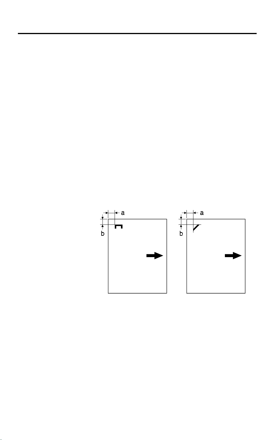
Stapling Position:
a = 6 ± 3 mm
b = 6 ± 3 mm
A658V500.wmf
Staple Replenishment: Cartridge exchange (2,000 staples/cartridge)
Power Source: DC 24 V (from the copier)
Power Consumption: Average: less than 35 W
Average for Sorting: less than 30 W
Average for Stapling: less than 33 W
Weight: 20.5 kg (27.4 lb)
Dimensions (W x D x H): 430 x 570 x 680 mm (15.0" x 21.6" x 17.5")
•
Specifications are subject to change without notice.
A658-1
Page 3
31 March 1997 COMPONENT LAYOUT
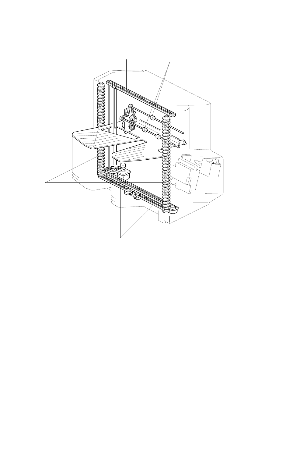
2. COMPONENT LAYOUT
2.1 MECHANICAL COMPONENT LAYOUT
1
2
7
3
Options
4
6
5
A658V501.wmf
1. Helical Wheels
2. Jogger Plate
3. Grip Assembly
4. Transport Rollers
5. Staple Unit
6. Bins
7. Proof Tray
A658-2
Page 4
COMPONENT LAYOUT 31 March 1997
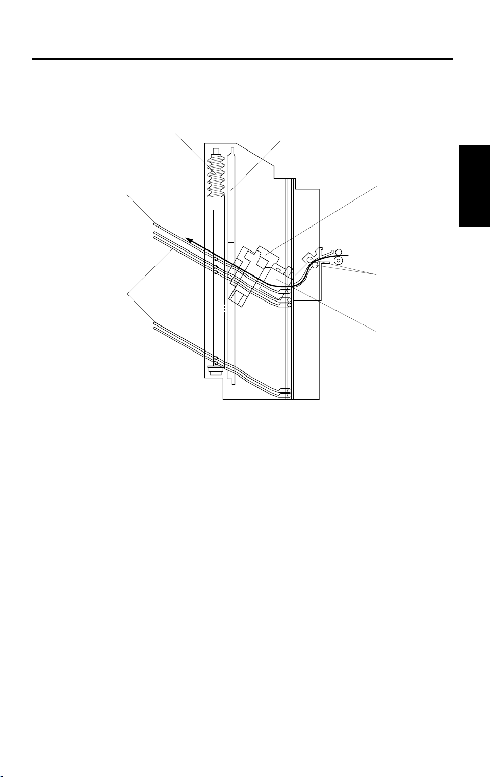
2.2 DRIVE LAYOUT
1
2
4
1. Jogger Drive Belt
2. Transport Roller
3. Wheel Drive Belts
4. Helical Wheels
3
A658V502.wmf
A658-3
Page 5
31 March 1997 COMPONENT LAYOUT
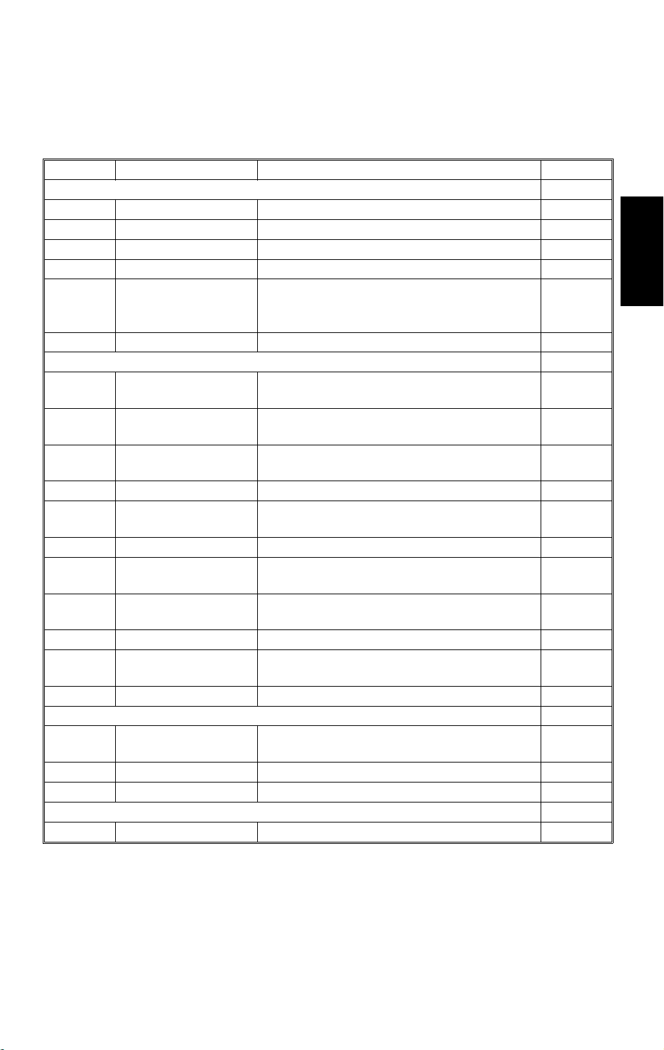
2.3 ELECTRICAL COMPONENT DESCRIPTION
Refer to the electrical component layout on the reverse side of the Point to
Point Diagram (on waterproof paper).
Symbol Name Function Index No.
Motors
M1 Main Drive Drives the transport roller 16
M2 Jogger Drives the jogger plate to square the copies 9
M3 Bin Drive Drives the bins 14
M4 Stapler Drives the stapler hammer 7
Grip Drives the gri ppers forwards a nd back into
M5
Sensors
S1
S2
S3
S4 Sorter Entrance Detects paper jams 2
S5
S6 Wheel Detects the bin position. 12
S7
S8
S9 Staple End Detects when the staples run out 18
S10
Bin
(Phototransistor)
Grip Home Position Detects when the grip assembly cam gear
Bin Home Positi on Detects w het her the bins are at home
Jogger Home Posi t i on Detects whether the jogger plat e i s in its
Bin
(LED)
Stapler Paper Detects whether any copies are under the
Staple Hammer
Home Position
the bin to grip the copies and br ing them to
the stap l ing posit i on
Detects whether there is any pap er in the
bins (light re cei ving element)
has rotated on ce
position
home posit ion
Detects whether there is paper i n th e bi ns
(light emitt i ng el ement)
hammer.
Detects whether the stapler hammer is at
home posit ion
3
1
6
11
13
10
4
17
Options
Switches
SW1
SW2 Stapler Cuts t he signals t o t he staple r. 8
Circuit Board
PCB1 Main Controls all sor t er /s ta pl er fu nct i ons 15
Door Safety Cuts the dc +24 V supply when either the
unit or the stap l er co ver is opened.
A658-4
5
Page 6
BASIC OPERATION 31 March 1997
3. BASIC OPERATION
3.1 NORMAL MODE AND SORT/STACK MODE
[F]
[E]
[A]
[C]
[B]
[D]
A658D500.wmf
Copies exiting the copier pass through the entrance guide plate [A]. The
transport roller will send copies either to the proof tray or to each bin,
depending on the selected mode.
During copying, all rollers in the sorter stapler transport the paper at a speed
which depends on the copier. When the trailing edge of the copy passes the
fusing exit sensor, the speed of the rollers changes to 600 mm/s. This makes
enough time for the jogger plate to square the stack of paper and to stack the
paper smoothly into the bins.
– Normal (proof) mode –
When the
!
key is pressed, the transport motor [B] energizes to rotate the
transport rollers [C]. The transport rollers send copies to the proof tray
directly.
– Sort mode –
When sort mode is selected, the bin drive motor [D] energizes to rotate the
helical wheels. The helical wheels [E] rotate twice to move the top bin to the
transport roller position, then the first copy is delivered to the top bin.
After the first copy of the first original has been fed to the top bin, the bin
drive motor moves the bins up one step (the helical wheels rotate once) so
that the second copy of the first original will be delivered to the next bin.
The jogger plate [F] squares the copies after each copy has been fed to a
bin. After the copies of the first original have been delivered to each bin, the
sorter stapler maintains its status (the bin drive motor does not rotate).
A658-5
Page 7
31 March 1997 BASIC OPERATION
The first copy of the second original is delivered to the final bin that was used
for the first original, then the final bin descends one step. The bins descend
each time a copy of the second original is delivered.
The direction of motion of the bins alternates for each page of the original
until the copy run is finished.
– Stack mode –
[A]
Options
A658D501.wmf
When stack mode is selected, the top bin advances to the transport roller
position in the same way as in sort mode.
After the first copy is delivered to the top bin, the jogger plate [A] moves
across to square the copy. The jogger plate squares the copies after each
copy has been fed to a bin.
After one set of copies for the first original has been delivered to the top bin,
the bin drive motor moves the bins up one step. Then, one set of copies of
the second original will be delivered to the next bin.
A658-6
Page 8
BASIC OPERATION 31 March 1997
3.2 STA PLE MODE
[B]
[C]
[A]
A658D502.wmf
[D]
A658D503.wmf
The stapler is only available in sort mode.
When the jogger plate has squared the final set of copies, the grip arms [A]
move inside the front side frame and catch the paper. The grip assembly
brings the copies into the stapler [B], and the stapler staples the copies.
After stapling, the grip assembly [C] brings the stapled copies back to the bin
and releases the copies. Then the grip assembly goes back to the normal
position. The bin either advances or descends one step [D] (depending on
whether the page is an odd or even numbered page of the original).
When the final set of copies has been stapled, the bins go back to the
standby position.
There are two staple modes.
– Automatic Stapling –
In ADF mode, when staple mode is selected before pressing the
!
key,
copies will be delivered to each bin and stapled automatically.
– Manual Stapling –
In platen cover mode, after the copies have been sorted into the bins, the
staple mode LED starts to blink. If the sort key is pressed while this LED is
blinking, the copies will be stapled.
A658-7
Page 9
31 March 1997 BASIC OPERATION
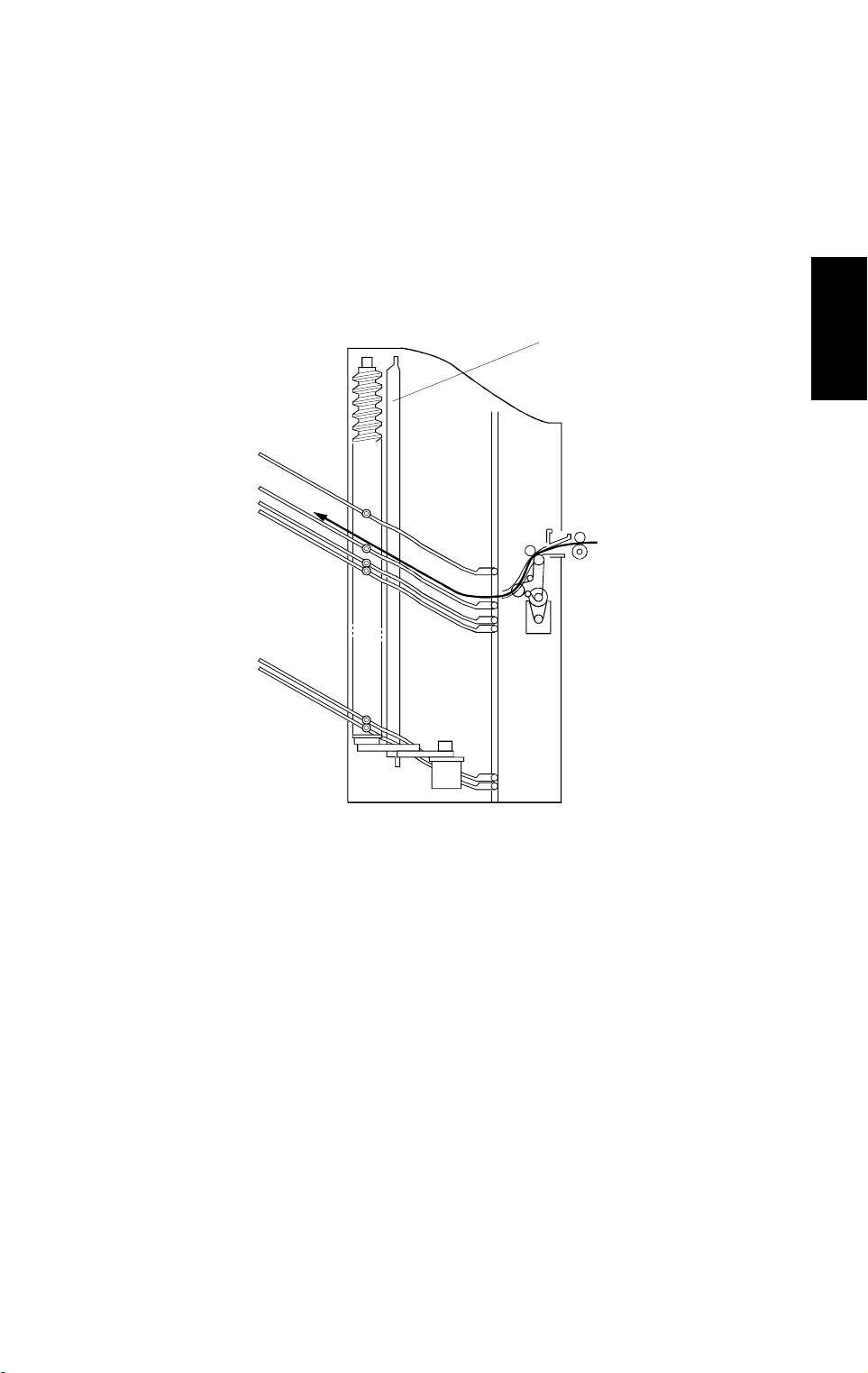
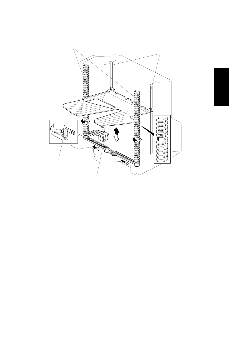
3.3 BIN DRIVE MECHANISM
[C]
[A]
Options
[E]
[D]
[B]
A658D504.wmf
The bin drive mechanism moves the bins up and down to receive copies.
There are four pins on each bin. Two pins fit into the slots [A] in both the front
and rear side frames; the pins slide up and down in these slots. The other
two pins fit into the slot in the helical wheels; as the helical wheels turn, these
pins move up and down, and the other pins move up and down in the slots at
the other end of the bin.
The bin drive motor [B] drives the helical wheels [C] through timing belts as
shown. When the motor rotates clockwise, the bins lift; when it rotates
counterclockwise, the bins lower. There is a wheel sensor [D] located under
the actuator [E] on the rear helical wheel; the actuator has a slot which
detects when the helical wheel has rotated once.
When the bins are advanced, the helical wheels rotate once for each step. As
the pitch of the spiral on the helical wheel is greater when the bins are at the
stapling and paper exit area than when the bins are elsewhere, the amount of
bin shift is greater when the bins are at the stapling and paper exit area. This
leaves enough space to staple and stack the copies. Also, this reduces the
total machine height.
A658-8
Page 10

BASIC OPERATION 31 March 1997
3.4 BIN HOME POSITION
[A]
A658D505.wmf
The bin home position sensor [A] ensures that the proof tray is lower than the
transport roller when the bins are in the home position.
When the main switch is turned on, the sorter stapler initializes itself to check
whether the component parts work or not. At this time, the bin drive motor
raises the bins for a few moments, then it lowers the bins until the bottom bin
actuates the bin home position sensor.
A658-9
Page 11

31 March 1997 BASIC OPERATION
3.5 JOGGER MECHANISM
[B]
[E]
Options
[C]
[A]
[D]
A658D506.wmf
The jogger motor [A] drives the jogger plate [B] through the timing belts [C].
The jogger is at home position when the actuator on the jogger plate goes
into the jogger home position sensor [D].
At standby, the jogger plate is at the home position. When the
!
key is
pressed, the copier sends the paper size information to the sorter stapler.
In sort, staple, and stack modes, the jogger moves three times to square the
stack of paper. First, when the paper has been fed completely into the bin (at
the proper time after the copy has passed through the entrance sensor [E],
depending on the paper length), the jogger motor moves the jogger plate out
of the jogger home position. Then, the jogger motor drives the jogger plate to
the width of the copy. Finally, the jogger plate moves inward to push all the
copies against the front side frame, which squares the sheets of paper. Then
the jogger plate returns to the home position.
A658-10
Page 12

BASIC OPERATION 31 March 1997
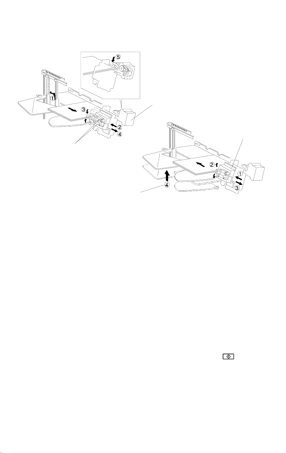
3.6 GRIP ASSEMBLY
[G]
A658D507.wmf
[F]
[J]
[H]
[D]
[I]
[B]
[E]
[C]
[A]
A658D508.wmf
A658D509.wmf
The grip assembly consists of the grip motor [A], the timing belt [B], the drive
gear [C], the grip home position sensor [D], and the cam gear [E].
The grip motor drives the cam gear through the timing belt and drive gear.
Cam gear rotation drives the mechanism that catches the copies and moves
the grip arm unit [F]. When the cam gear rotates clockwise one full turn, the
grip arm moves to catch the copies and returns to the home position to
prepare for stapling. After stapling, the cam gear rotates counterclockwise
once so that the stapled copies go back to the bin, and the cam gear returns
to its home position.
When the cam pushes the roller [G] on the lever [H] and the lever pushes the
grip arm, the grip arm can catch the copies.
A pin [I] on the cam gear fits into the slot in the grip arm unit. So, when the
cam gear rotates, the slot moves the grip arm unit inward and outward.
The actuator [J] on the cam gear activates the grip home position sensor
once every rotation of the cam gear. This allows the sorter stapler to
determine that the cam gear has rotated once.
A658-11
Page 13

31 March 1997 BASIC OPERATION
3.7 STA PLER UNIT
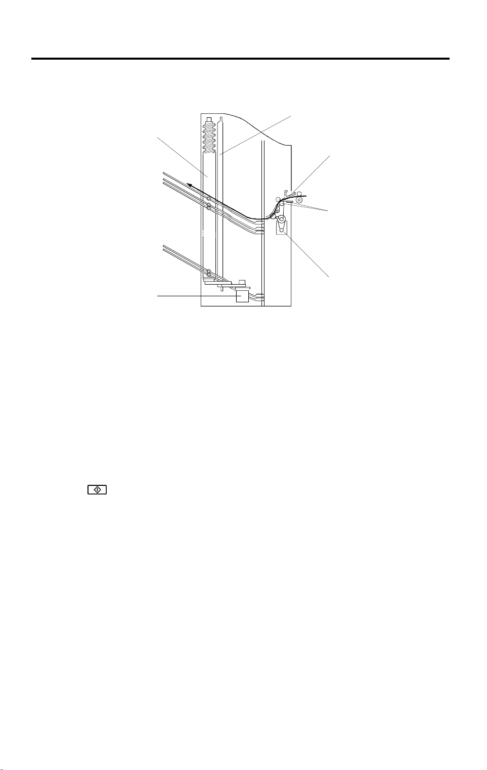
[C]
[D]
[A]
[G]
[F]
Options
[H]
[B]
[E]
A658D510.wmf
The stapler motor [A] drives the staple hammer [B] using the gears [C] and
the eccentric cam [D].
The roller [E] feeds the staple sheets under the hammer.
When the aligned copies are brought to the staple position by the grip unit,
the stapler motor starts rotating and the copies are stapled. When the cam
completes one rotation, the staple hammer home position sensor [F] is
deactuated and the stapler motor stops.
When the stapler paper sensor [G] in the grip assembly does not detect any
copies under the hammer, the stapler motor does not rotate.
When the trailing edge of the last staple sheet pass through the staple end
sensor [H], the sorter stapler enters the staple near end condition. After the
current job is completed, the Add Staples indicator lights on the operation
panel. Then the copier cannot be used whenever the staple mode is
selected.
A658-12
Page 14

BASIC OPERATION 31 March 1997
3.8 STAPLER SWITCH
[A]
[B]
A658D511.wmf
The stapler switch [A] below the grip assembly cuts the dc +24 V supply to
the stapler. In proof mode, all bins lower and push the lever [B]. This opens
the stapler switch so that the signal to the stapler is cut. In sort and staple
modes, all bins are advanced and the switch is closed so that the signal can
be supplied to the stapler.
– Staple Mode Disabling Conditions –
1. Under the following conditions, staple mode is disabled.
•
If there is paper in a bin before the main switch is turned on.
•
If the selected paper size does not match the stapling specifications.
•
If the paper is fed from the by-pass feed table.
•
If the stack or interrupt modes are selected.
2. Under the following conditions, staple mode is canceled if it had been
selected.
•
If paper is inserted into a bin by hand while the staple mode is
selected.
•
If only one sheet is delivered to the bin.
•
If the number of sheets to be stapled exceeds the stapler capacity.
A658-13
Page 15

31 March 1997 BASIC OPERATION
3.9 PAPER FEED AND MISFEED DETECTION TIMING
– Proof Mode –
A4 sideways, 5 copies, 150 mm/s
*1:The value of the low speed depends on the copier.
– Sorter Mode –
A4 sideways, two copies a of two-page original, 15 0 m m/s
Options
A658D512.wmf
A658D513.wmf
*1:The start times of the bin drive and the jogger motors depend on the
paper size as shown in the following table.
*2:Bin No.
Paper Size
A3/11"x17" 80 ms 270 ms
B4 160 ms 190 ms B5 sideways 160 ms 190 ms
A4 sideways/
1/2
11"x8
"
Bin drive
motor t iming
80 ms 270 ms B5 lengthwise 310 ms 40 ms
Jogger
motor t iming
A658-14
Paper Size
A4
lengthwise/
1/2
"x11"
8
Bin drive
motor timing
254 ms 96 ms
motor timing
Jogger
Page 16

BASIC OPERATION 31 March 1997
– Staple Mode –
A4 sideways, two copies of a two-page original, aft er sorting, 150 mm/ s
A658D514.wmf
A658-15
Page 17

31 March 1997 BASIC OPERATION
3.10 JAM DETECTION
– Paper Jam –
A4 sideways
A658D515.wmf
J1: The sorter entrance sensor does not turn on within 2 s after the fusing
exit sensor has turned on.
J2: The fusing exit sensor does not turn off within 11.4 s after the sorter
entrance sensor has turned on.
Options
J3: The sorter entrance sensor does not turn off within 1 s after the fusing
exit sensor has turned off.
– Staple Jam –
In the following conditions, a staple jam will occur and the sorter jam indicator
on the operation panel will light.
1. If the stapler paper sensor is on when the main switch turns on or just as
the stapler cover is closed.
2. If the stapler paper sensor stays on after the stapling job has been
finished.
A658-16
Page 18

REPLACEMENT AND ADJUSTMENT 31 March 1997
4. REPLACEMENT AND ADJUSTMENT
4.1 EXTERIOR COVER REMOVAL
[D]
[C]
[B]
[E]
[A]
4.1.1 Front Cover
1. Remove the front cover [A] (2 screws).
4.1.2 Rear Cover
1. Remove the rear cover [B] (3 screws).
4.1.3 Top Cover
1. Remove the rear cover [B].
2. Remove the top cover support bracket [C] (1 screw).
3. Remove the top cover [C] (1 screw).
4.1.4 Lower Cover
1. Remove the front cover [A] and the rear cover [B].
2. Remove the lower cover [E].
A658R506.wmf
A658-17
Page 19

31 March 1997 REPLACEMENT AND ADJUSTMENT
4.2 STAPLER UNIT REMOVAL
[A]
[B]
Options
[A]
A658R500.wmf
1. Remove the front cover. (See Exterior Cover Removal.)
2. Loosen the screws [A].
3. Remove the staple unit [B], as shown (1 screw and 1 connector).
A658-18
Page 20

REPLACEMENT AND ADJUSTMENT 31 March 1997
4.3 GRIP ARM REPLACEMENT
[A]
[C]
[B]
[D]
A658R501.wmf
[F]
[E]
A658R502.wmf
1. Remove the front cover. (See Exterior Cover Removal.)
2. Remove the grip assembly [A] (4 screws, 2 connectors, and 1 grounding
wire).
3. Remove the spring [B] and remove the slider [C].
4. Remove the grip arm unit [D] (1 screw and 1 clip).
5. Remove the grip arm plate [E] (2 screws).
6. Replace the grip arms [F].
A658-19
Page 21

31 March 1997 REPLACEMENT AND ADJUSTMENT
4.4 BIN REMOVAL
[C]
[A]
Options
[B]
[D]
A658R503.wmf
[D]
[E]
[F]
A658R504.wmf
1. Remove the front, rear, and top covers. (See Exterior Cover Removal.)
2. Remove the upper stay bracket [A] (4 screws and 1 connector).
3. Loosen the two screws [B], then remove the timing belt [C].
4. Remove the brackets [D] (3 springs each).
5. While moving the helical wheels [E] outward, remove the bins [F].
[E]
A658-20
Page 22

REPLACEMENT AND ADJUSTMENT 31 March 1997
4.5 TRANSPORT MOTOR REMOVAL
[A]
A658R505.wmf
1. Remove the sorter stapler (1 screw and 1 chain).
2. Remove the rear cover. (See Exterior Cover Removal.)
3. Remove the transport motor [A] (2 screws and 4 washers).
A658-21
Page 23

31 March 1997 INSTALLATION
11.7 20-BIN SORTER STAPLER (A658) ACCESSORY CHECK
Check the accessories against the following list:
Description Q’ty
1. Staple Position Decal ....................................................... 1
2. Chain ................................................................................ 1
3. Cap Remover ................................................................... 1
4. Philips Pan Head Screw - M4 x 14................................... 5
5. New Equipment Condition Report (Multi-language)......... 1
6. Installation Procedure (English)........................................ 1
7. Stepped Screw ................................................................. 1
Copier
55
Page 24

INSTALLATION 31 March 1997
11.8 20-BIN SORTER STAPLER (A658) INSTALLATION
PROCEDURE
[A]
A658I500.wmf
A658I501.wmf
[C]
CAUTION
[B][D]
A658I508.wmf
Unplug the copier power cord before star ting the follo wing procedure.
When handling the sorter stapler, make sure to hold the parts shown
[A]. Otherwise, the resulting damage may cause paper jams at the
entrance.
NOTE:
1) Keep the shipping retainers after installing the machine. They will
be reused if the machine will be transported to another location.
2) Proper reinstallation of the shipping retainers is required in order
to avoid any transport damage.
3) A sorter adapter (A568) is required to install this sorter stapler in
the A208/A210/A211 copiers. Before installing this sorter stapler,
please install the sorter adapter.
1. Remove the strips of tape and the shipping retainers as shown.
2. Open the front door [B] and remove the cardboard [C] and the strip of
tape [D] from the staple unit. Close the front door.
56
Page 25

31 March 1997 INSTALLATION
Copier
[A]
A658I502.wmf
[B]
A658I503.wmf
3. Remove the two plastic caps [A] from the copier left cover with nippers.
[C]
4. By releasing the open lever [B] of the sorter stapler, remove the sorter
stapler mounting frame [C], as shown.
57
Page 26

INSTALLATION 31 March 1997
[C]
[E]
[F]
[B]
[A]
[G]
[D]
A658I504.wmf
A658I505.wmf
[H]
A658I506.wmf
5. Remove the M4 x 8 round head screws (2 screws [A] for the
A204/A206/A207 copiers
copiers
) from the left cover of the copier.
, 3 screws [A] and [B] for
A208/A210/A211
6. Mount the sorter stapler mounting frame [C] on the copier as shown
(4 screws M4 x 14 and 1 stepped screw [D]).
NOTE:
When hooking the sorter stapler mounting frame on the left side
of the copier, make sure that the positioning hooks [E] on the
frame are properly inserted in the positioning holes [F] in the
copier.
7. Install the sorter stapler [G] on the frame (2 hinge pins at the rear) as
shown.
8. Tighten the M4 x 14 screw [H].
NOTE:
This screw prevents the sorter stapler from falling down.
58
Page 27

31 March 1997 INSTALLATION
[A]
[B]
[D]
Copier
[C]
A658I507.wmf
9. Connect the cable [A] and the optic cable [B].
10. Install the chain [C] as shown.
11. Attach the staple position decal [D], as shown.
12. Plug in the copier.
13. Turn on the main switch of the copier and test the operation of the sorter
stapler.
NOTE:
The copier automatically recognizes that the sorter stapler has
been installed.
59
Page 28

20 BIN SORTER STAPLER (A658) ELECTRICAL
COMPONENT LAYOUT
16
1
2
3
15
4
5
6
14
7
13
12
11
18
10
9
A658S501.wmf
8
A658S500.wmf
17
Page 29

Description Index No. P to P Location
Bin Sensor (Photo t r.) (S1) 1 I16
Sorter Entrance Se nsor (S4) 2 H16
Grip Motor (M5) 3 H2
Stapler Paper Sensor (S8) 4 C16
Door Safety Switch (SW1) 5 A5
Grip Home Posit i on Sensor (S2) 6 D16
Stapler Motor (M4) 7 D1
Stapler Switch (SW2) 8 F5
Jogger Motor (M2) 9 G2
Bin Sensor (LED) (S7) 10 L16
Bin Home Position Sensor (S3) 11 K16
Wheel Sensor (S6) 12 B16
Jogger Home Posi t ion Sensor (S5) 13 A16
Bin Drive Motor (M3) 14 J2
Main Board (PCB 1) 15 F8
Main Drive Motor (M1) 16 F17
Staple Home Posi tion Sensor (S10) 17 E1
Staple End Sensor (S9) 18 E1
 Loading...