

Ricoh ST28 SPECIFICATIONS

SORTER STAPLER
(Machine Code: A606)
15 July 1996 SPECIFICATIONS
1. SPECIFICATIONS
Configuration: Console
Number of Bins: 20 + Proof Tray
Paper for Proof Tray:
Size Maximum: A3, 11" x 17"
Minimum: A6 lengthwise, 5
1/2
" x 8
1/2
"
Weight: 52 ~ 157 g/m
2
,14 ~ 42 lb
Capacity: 250 sheets (80 g/m
Paper for Bins: See the table below.
Sort Stack Staple Punch
Maximum paper
size
Minimum paper
size
Maximum paper
weight
Minimum paper
weight
Maximum
capacity
A3, 11" x 17" A3, 11" x 17" A3, 11" x 17" A3, 11" x 17"
Sideways:
1/2
A5, 8
Lengthwise:
A5, 5
157 g/m
52 g/m
all sizes:
50 sheets/bin
2 sided copies:
40 sheets/bin
" x 11"
1/2
" x 8
2
, 42 lb 157 g/m2, 42 lb 80 g/m2, 20 lb 128 g/m2, 34 lb
2
, 14 lb 52 g/m2, 14 lb 64 g/m2, 17 lb 52 g/m2, 14 lb
Sideways:
A4, 8
Lengthwise:
1/2
"
A5, 5
all sizes:
40 sheets/bin
2 sided copies :
35 sheets/bin
1/2
1/2
" x 11"
1/2
" x 8
"
2,
20 lb)
1/2
B5, 8
all sizes:
50 sheets
" x 11" A5 (2 holes)
B5 sideways
1/2
8
" x 11" side
ways (3 holes)
(2 holes)
104 g/m2, 28 lb
(3 holes)
all sizes:
40 sheets
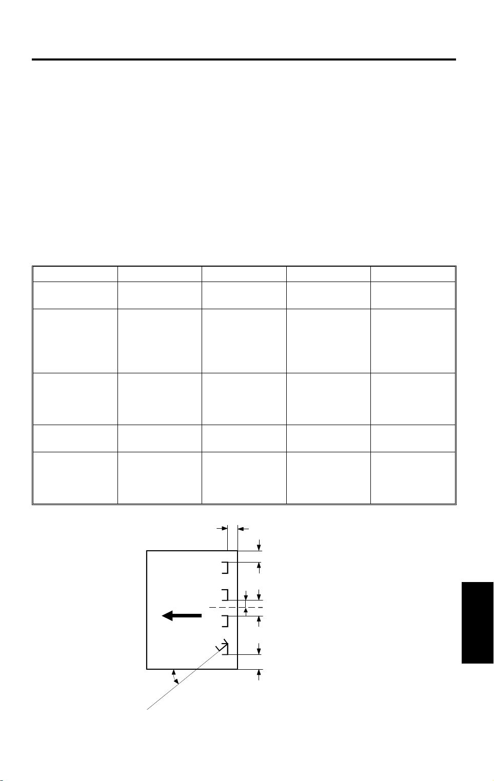
Staple Position:
a
a = 6 ± 3 mm
c
b = 6 ± 3 mm
c = 6 ± 3 mm
d
e
d = 66 ± 3 mm
e = 132 ± 2 mm
θ = 45 ± 5°
Sorter
b
θ
A606V500.wmf
1

SPECIFICATIONS 15 July 1996
Staple Replenishment: Cartridge refile (5,000 pieces/cartridge)
Power Source: DC24 V (from copier)
Power Consumption: Average: less than 60 W (without punch)
less than 70 W (with punch)
Maximum:
i n sort/stack mode: less than 60 W (without
punch)
less than 70 W (with punch)
i n staple mode: less than 45 W
Dimensions:
566 x 583 x 978 mm
(W x D x H)
Weight: Approximately 52 kg
Punch Position: 2 Holes (European version)
a = 12 ± 3 mm
a
b = 40 ± 3 mm
c = 80 ± 1 mm
φ
d
b
c
3 Holes (U.S.A. version)
3/8
a = 9.5 (
c = 216 (8
d = 108 (4
") ± 3 mm
1/2
") ± 1 mm
1/4
") ± 1 mm
d’= ± 3 mm
d’
Punch Hole Size:
2 Holes: φ = 6. 5 ± 0. 5 mm
3 Holes: φ = 8. 0 ± 0. 5 mm
A606V503.wmf
2
15 July 1996 COMPONENT LAYO UT
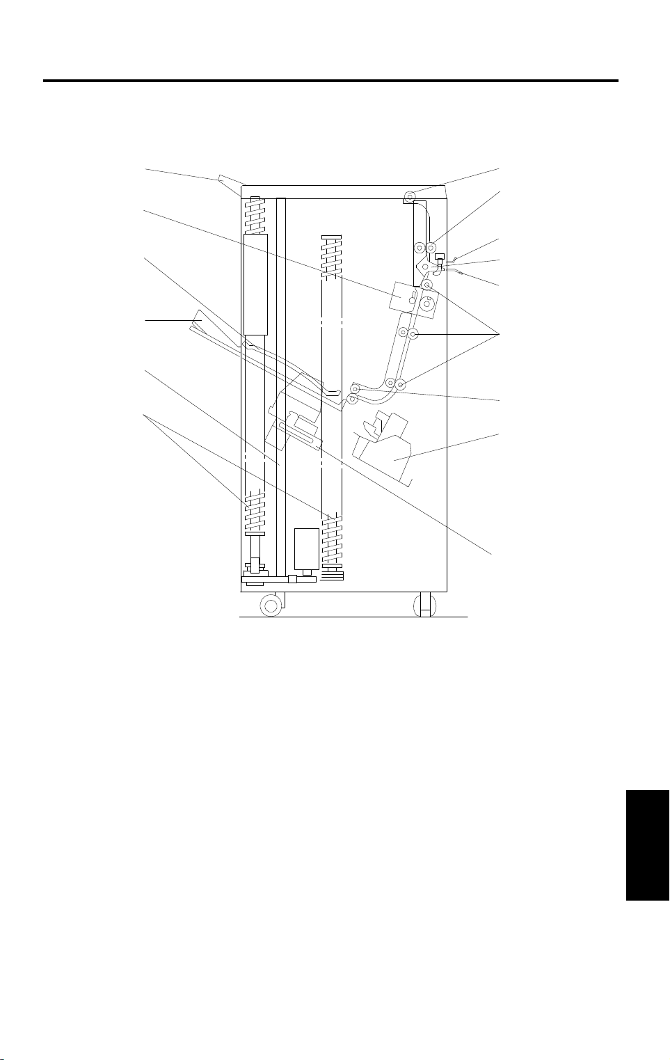
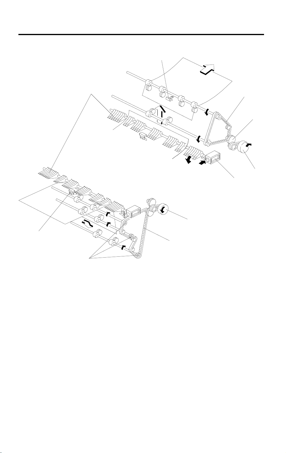
2. COMPONENT LAYOUT
2.1 MECHANICAL COMPONENT LAYOUT
1
2
3
15
4
14
5
6
13
7
12
8
11
9
10
1. Proof Tray
2. Proof Exit Rollers
3. Proof Transport Rollers
4. Upper Entrance Guide
5. Turn Gate
6. Lower Entrance Guide
7. Sorter Transport Rollers
8. Sorter Exit Rollers
A606V501.wmf
9. Staple Unit
10. Grip Assembly
11. Helical Wheels
12. Jogger Plate
13. Bins
Sorter
14. Upper Guide Plate
15. Punch Unit (Punch version only)
3
COMPONENT LAYOUT 15 Jul y 1996
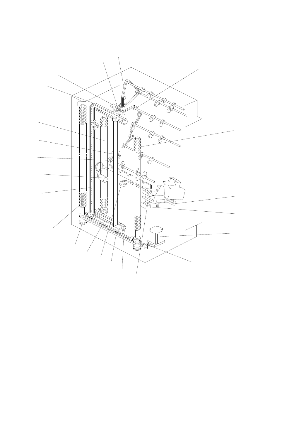
2.2 DRIVE LAYOUT
3
2
4
1
13
5
5
16
15
14
13
6
7
5
9
13
1. Main Motor
2. Main Drive Belt
3. Proof Drive Belt
4. Sorter Drive Belt
5. Helical Wheels
6. Staple Unit Drive Belt
7. Gripper Motor
8. Bin Drive Motor
12
11
8
9
9
10
A606V502.wmf
9. Wheel Drive Belts
10. Grip Drive Belt
11. Jogger Motor
12. Staple Unit Drive Motor
13. Jogger Drive Belts
14. Bin Rear Plate Drive Motor
15. Sorter Exit Drive Belt
16. Sorter Exit Motor
4

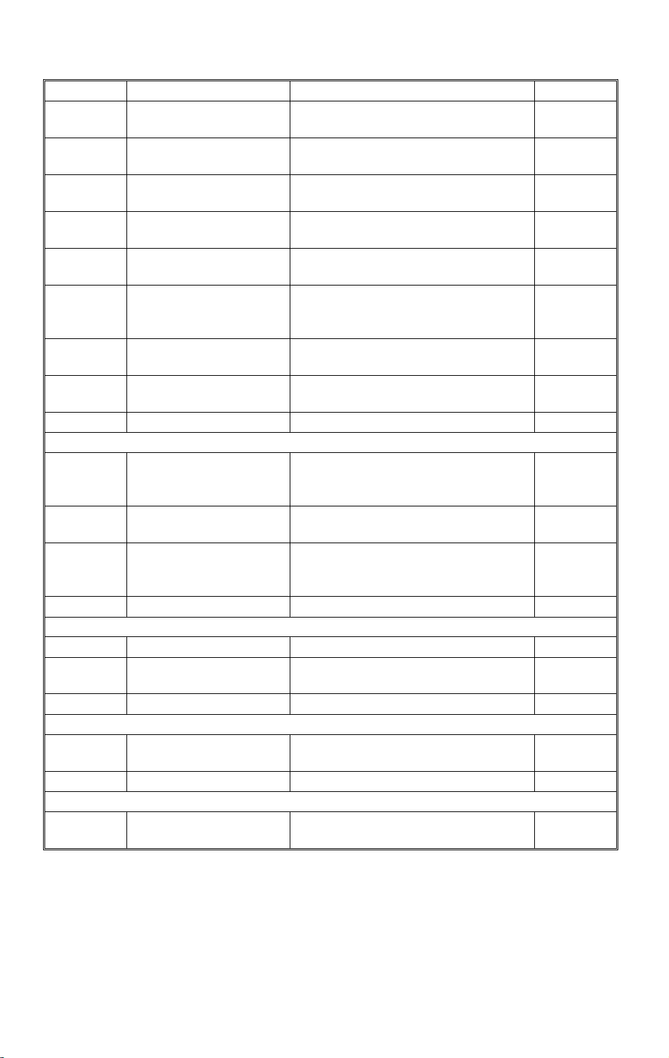
15 July 1996 ELECTRICAL COMPONENT DESCRIPTION
3. ELECTRICAL COMPONENT DESCRIPTION
Please refer to the electrical component layout on the reverse side of the
Point to Point (Water Proof Paper) for symbol and index number.
Symbol Name Function Index No.
Motors
M1 Main Drives the paper tr ansport roller s. 1
M2
M3
M4
M5
M6
M7 Bin Rear Plate Dr i ve Drives the bin rear plate down and up. 24
M8 Sorter Exit Delivers the pape r int o t he bi ns. 27
M9
Staple Feeds the staple s and drives the
stapler hamm er .
Grip Drives the grip assembly forward and
backward into the bi n to grip the
copies and bring t hem to the staplin g
position.
Bin Drive Drives the bins upw ard and downwar d
by rotating the thr ee helical wheel s.
Jogger Drives the jogger pl at e t o jog the
copies agains t the f ront side plate.
Staple Unit Dri ve Drives the stapl e uni t according to the
staple position and angle.
Punch Drive
(Punch versio n onl y)
Drives the hole puncher.
10
16
18
20
23
33
Sensors
Bin Jam (LED) Detects if there is paper jams at the
S1
S2
S3
S4
S5 Staple End Detects staple end . 9
S6
S7
S8
S9
S10 Wheel Sensor Detects the bin position. 19
Proof Exit Detects paper jams at the pr oof tr ay
Entrance Detects paper jams at entranc e
Staple HP Detects if the staple hammer is in the
Paper Detects whether copies are under the
Staple Unit HP Detects if the staple unit is in the
Grip HP Detects if the grip assembly is in the
Bin Jam (Photo Tr. ) Detects paper jams at the distri but i on
distribution sect i on and detects if there
is paper in the bi ns ( l i ght emitting
element).
exit.
guides.
home position.
hammer.
home position.
home position.
section and detects if there is paper in
the bins (light receiving element).
3
4
5
8
11
13
15
17
Sorter
5
ELECTRICAL COMPONENT DESCRIPTION 15 July 1996
Symbol Name Function Index No.
S11
S12
S13
S14
S15
S16
Bin HP Detect s i f the b i ns ar e i n t he home
position.
Jogger HP Detects if the jogger plate is in the
home position.
Bin Rear Plate Open Detects if the bin rear plate is in the
open position.
Bin Rear Plate HP Detects if the bin rear plate is in the
home (closed ) position.
Punch Home position
(Punch versio n onl y)
Punch Rubbish (w aste)
Detects if the hole puncher is in the
home position.
Detects punch rubbish overflow.
Overflow
21
22
25
26
30
31
(Punch versio n onl y)
S17
S18
Cartridge Set Detects if the sta pl e cartridge is
installed or not.
Staple Unit
Pulled-out pos i tion
Detects if the staple unit is in the
pulled-out pos i tion.
7
—
Solenoids
Turn Gate Opens and closes the turn gate to
SOL1
direct the copies i nt o either the proof
tray or the bins.
SOL2
Grip Opens and closes the gri p ar ms to
grip copies on the bins.
Grip Arm Positioni ng Moves the grip ass ’y to the rear and
SOL3
front to catch or rel ease the paper to
carry to the stapler.
PCBs
PCB1 Main Contro l Controls all so rter stapler functio ns. 28
PCB2
Punch Control
(Punch versio n onl y)
Control the punch f unction
Switches
SW1
Door Safety Cuts the DC power when the front
door is opened.
Others
Ohter1
Punch Unit
(Punch versio n onl y)
—32
2
12
14
29
6
6
15 July 1996 BASIC OPERATION
4. BASIC OPERATION
4.1 NORMAL (PROOF MODE) AND SORT/STACK MODE
[D]
[C]
[A]
[A]
[B]
A606D500.wmf
Copies exiting the copier pass through the entrance guide plates [A] to the
turn gate section. The turn gate [B] will send copies either to the proof tray or
to the bins, depending on the mode.
- Normal (proof) mode - (from the turn gate section to the proof tray)-
The turn gate solenoid energizes to turn the turn gate clockwise when the
Start key is pressed. The main motor turns counterclockwise to rotates the
vertical transport rollers [C] and proof exit roller [D]. The turn gate directs
copies through the proof transport section to the proof tray.
7
Sorter
BASIC OPERATION 15 July 1996
- Sort mode - (from the turn gate section to the bins)
[F]
[A]
[E]
[D]
[B]
[H]
[C]
[I]
[G]
A606D501.wmf
In this mode, the turn gate solenoid stays off to keep the turn gate [A] at the
upper position. The main motor turns clockwise to rotates the sorter transport
rollers [B] and the exit motor rotates the exit rollers [C].
The turn gate directs copies to the sorter bins through the sorter transport
section, then the first copy is delivered between the top bin [D] and the upper
guide plate [E].
The jogger plate [F] then jogs to square the copies each time.
Before the next copy reaches the sorter exit roller, the bin drive motor [G]
rotates and advances the bin one step (the helical wheels [H] rotate once).
When the cut out of the actuator reaches below the wheel sensor [I], the bin
drive motor turns off.
Bins advances each time copies are delivered.
8
15 July 1996 BASIC OPERATION
- Stack mode - (from the turn gate section to the bins)
[F]
[A]
[E]
[D]
[B]
[H]
[C]
[I]
[G]
A606D501-2.wmf
As with sort mode, the turn gate solenoid stays off and the turn gate [A] also
stays up when the start key is pressed. The main motor turns clockwise to
rotate the sorter transport rollers [B] and the exit motor rotates the exit rollers
[C].
The turn gate directs copies to the sorter bins through the sorter transport
section, then the copies are delivered between the top bin [D] and the upper
guide plate [E].
The jogger plate [F] then jogs to square the copies each time.
All copies of the copy run are then fed to the first bin. When the final copy is
delivered, the wheel drive motor [G] turns and advances the bin one step (the
helical wheels [H] rotate once). When the cut out of the actuator reaches
below the wheel sensor [I], the bin drive motor turns off.
Sorter
9

BASIC OPERATION 15 July 1996
4.2 STA PLE MODE
[Fig. 1]
A606D502.img
[Fig. 2]
A606D503.img
[Fig. 3]
A606D504.img
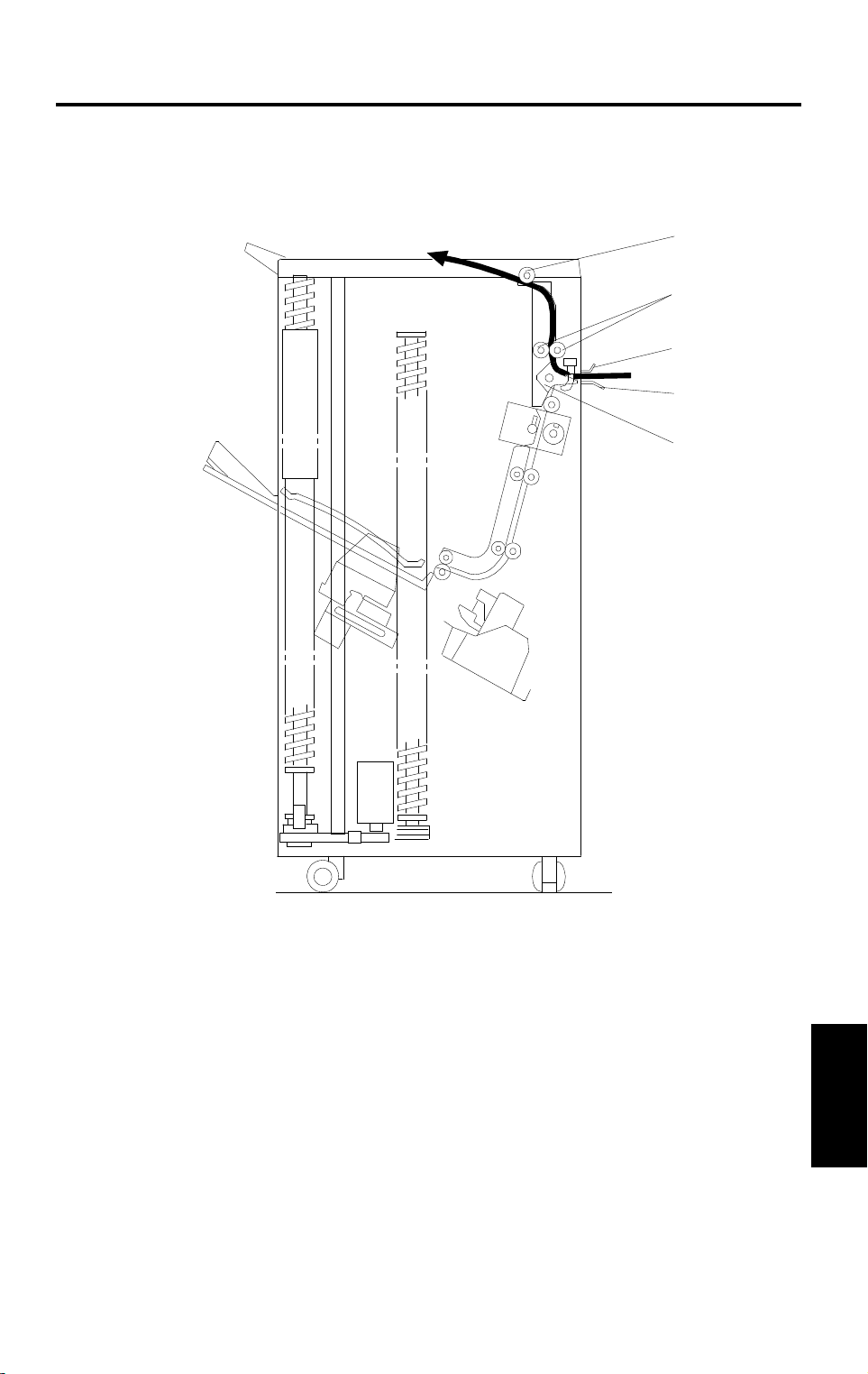
When the final set of copies is jogged [Fig. 1], the staple unit staples the
stacked copies as follows: The grip arms move inside the front side plate and
catches the paper. The bin rear plate is turned so as to be flat with the sorter
bin. The grip assembly brings the copies down underneath the stapler [Fig.
2]. The staple unit changes the position (the position varies depending on the
copy size and staple mode) and the stapler staples the copies [Fig. 3].
10
15 July 1996 BASIC OPERATION
[Fig. 4]
A606D505.img
[Fig. 5]
A606D506.img
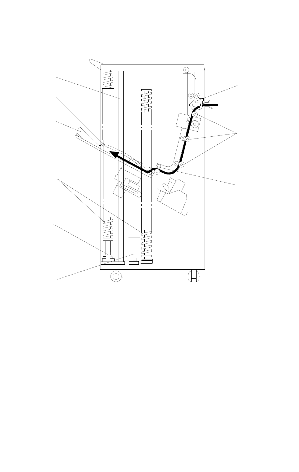
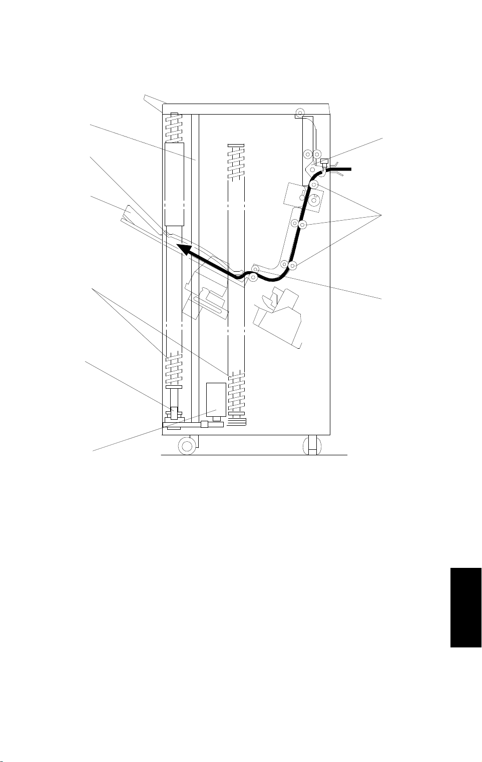
The grip assembly brings the stapled copies back to the bin and the bin rear
plate returns to the original position.
The grip assembly releases the copies and return to outside the front side
plate so as not to disturb the bin movement [Fig. 4].
The bin advances one step [Fig. 5].
When the final set of copies is stapled, the staple unit is returned to the home
position.
There are two staple modes.
1) Automatic stapling:
In ADF mode, when the staple mode is selected before pressing the start
key, copies will be delivered to each bin and stapled automatically.
2) Manual stapling:
In sort mode, after copies are sorted in the bins, the copies will be stapled
when the manual staple key is pressed then staple position is selected. In
stack mode, manual stapling is impossible.
Sorter
11
TURN GATE SECTION 15 July 1996
5. TURN GATE SECTION
[A]
[I]
[D]
[G]
[C]
[B]
A606D507.wmf
[C]
[H]
[E]
[F]
A606D508.wmf
The turn gate [A] sends copies to the proof tray or the sorter bins depending
on the mode. In the proof mode, the turn gate solenoid [B] turns on and the
main motor [C] turns clockwise when the start key is pressed.
The turn gate [A], directs copies upward through the proof transport section
to the proof tray. In this mode, the main motor drive is transmitted by both the
proof drive belt [D] and sorter drive belt [E]. However the one way clutch in
each sorter transport roller drive gear [F] does not transmit the drive to the
sorter transport rollers.
In the sort, stack and staple modes, the turn gate solenoid stays off to direct
copies downward to the sorter transport section. When the start key is
pressed, the main motor [C] turns counterclockwise.
In this mode, the main motor drive is not transmitted to the proof drive belt [D]
because of the one way clutch in the pulley [G].
The entrance [H] and the proof exit [I] sensors monitor the paper jam.
12
15 July 1996 BIN DRIVE MECHANISM
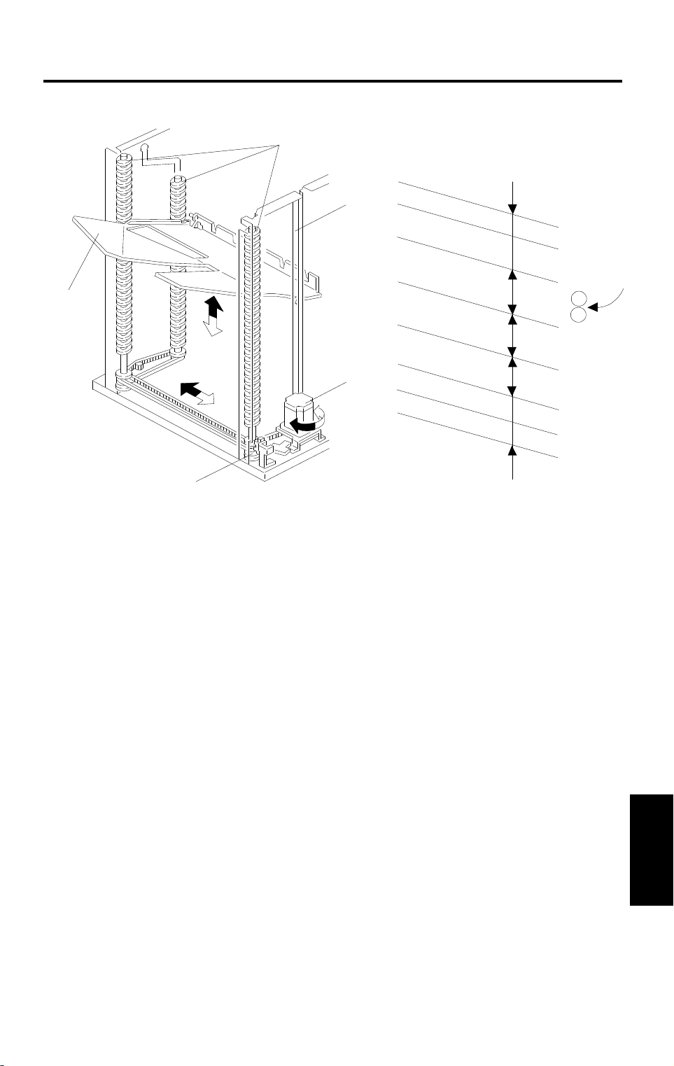
6. BIN DRIVE MECHANISM
[B]
[E]
15
30
[G]
[D]
45
[F]
40
[A]
40
15
15
[C]
A606D509.wmf
A606D510.wmf
The bin drive mechanism moves the bins up and down to receive copies. The
main components in this mechanism are the bin drive motor [A], the three
helical wheels [B], the wheel sensor [C], and the bins [D] themselves. There
are four pins on each bin. Three of them fit in the slot on the helical wheels.
Another pin fits into the slot [E] of the front side frame.
The pins slide up and down in these slots.
Three timing belts transmit the drive from the bin drive motor to the three
helical wheels. When it rotates clockwise, the bins lift (black arrow) and when
it rotates counterclockwise, the bins lower (white arrow). There is a wheel
sensor actuator on the front helical wheel, the actuator has a slot which
detects when the helical wheel has rotated 360 degrees.
When the bins are advanced, the helical wheels rotate once (360 degrees )
for each step.
As the pitch of the spiral on the helical wheel is greater when bins are at the
staple and paper exit area than when bins are elsewhere, the amount of bin
shift is greater when bins are at the staple and paper exit area. This leaves
enough space to staple [F] and stack paper [G] and reduces the total
machine height.
Sorter
13
BIN HOME POSITION 15 July 1996
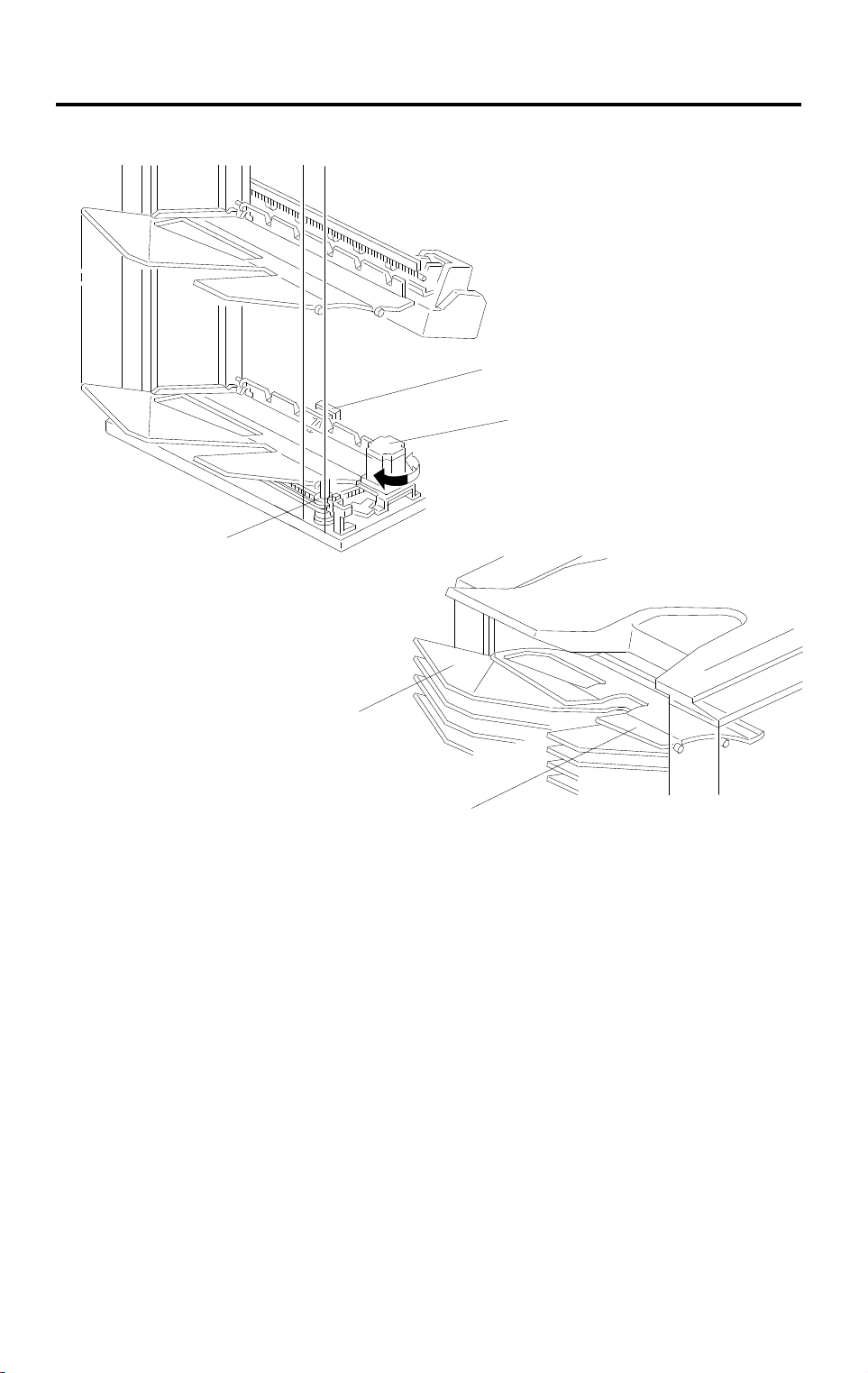
7. BIN HOME POSITION
[A]
[E]
[B]
A606D511.wmf
[D]
[C]
A606D512.wmf
The bin home position sensor [A] and the wheel sensor [B] ensure that the
sorter exit roller is between the upper guide plate [C] and the 1st bin [D] when
all the bins are in the home position.
When the main switch is turned on, the bin lift motor [E] lowers the bins (turns
counterclockwise) until the bottom bin actuates the bin home position sensor.
Then, the bin lift motor raises the bins (turns clockwise) until the wheel
sensor activates. Thus, the bins are in the home position.
14

15 July 1996 JOGGER SECTION
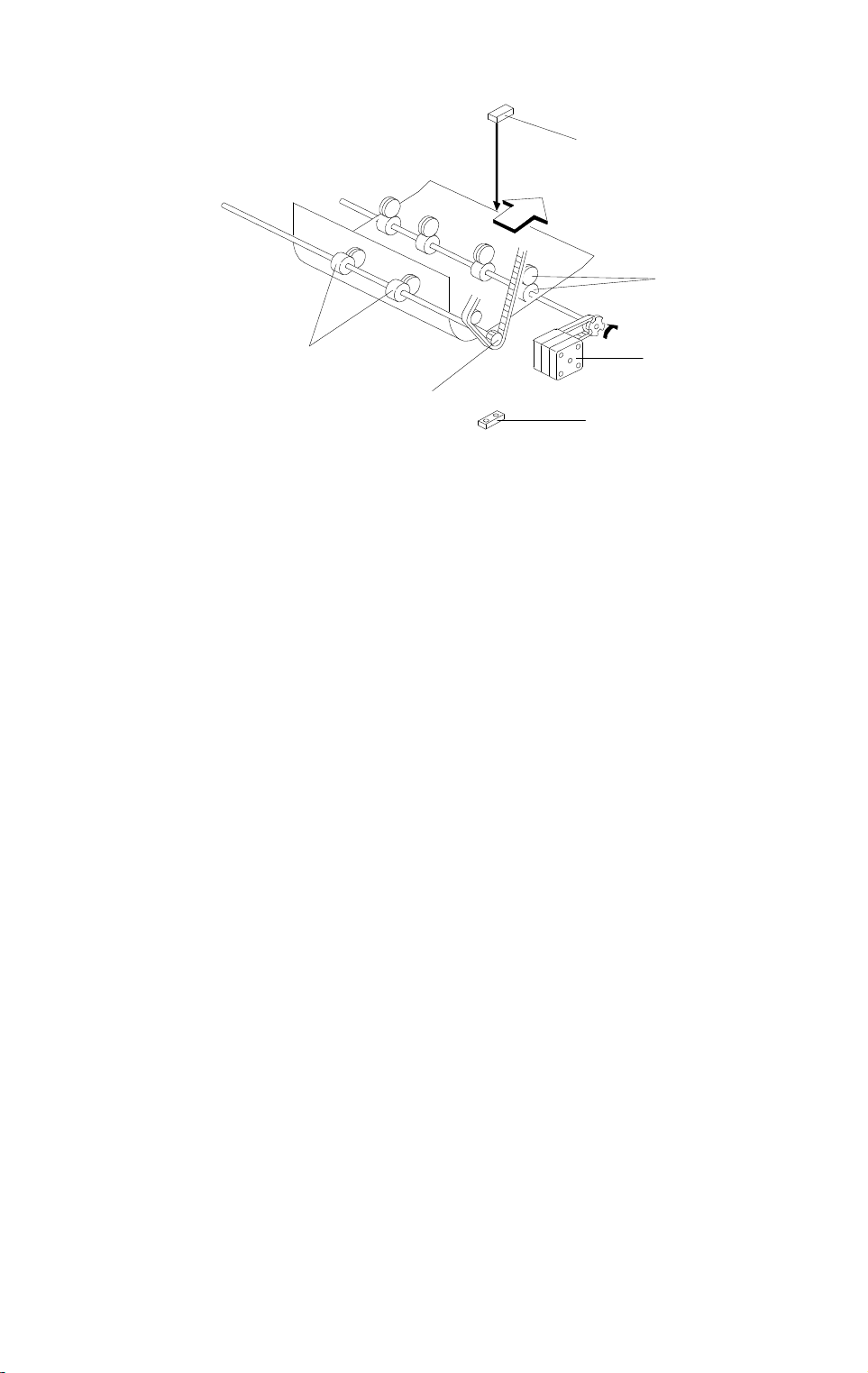
8. JOGGER SECTION
[B]
[A]
A606D513.wmf
Copier Main
Motor
Jam Sensor
Jogger Motor
ON
300 ms
A606D514.wmf
When the Start key is pressed in the sort, staple and stack modes, the copier
sends the paper size information to the sorter stapler. In accordance with this
data, the jogger motor [A] drives the jogger plate [B] from the jogger home
position to where the width is 10 mm wider than the selected paper.
300 ms after the trailing edge of the copy passes underneath the jam sensor,
the jogger motor rotates forward and in reverse. This makes the jogger plate
push all the copies against the front side plate to square the sheets. When
the jogger plate pushes the paper, the plate shifts to a position 5 mm wider
than the paper size when the bins lift. It shifts to a position 1 mm narrower
than the paper size when the bins lowers.
Sorter
The jogger plate returns to 10 mm away from the selected paper size for the
next copy.
When the bin sensor detects that all copies are removed from the bins after
jogging is finished, the jogger plate returns to its home position.
15
JOGGER SECTION 15 July 1996
[C]
[B]
Fig. 1
[D]
[A]
[E]
[C]
A606D515.wmf
Normally all rollers in the sorter stapler transport the paper at a speed of 360
mm/s.
To have enough paper jogging time, the sorter exit motor [A] rotation speed
changes to transport the paper quickly and to stack the paper smoothly into
the bins as follows:
360 mm/s: When the sorter exit roller [B] catches the leading edge of the
paper
1,000 mm/s: After the jam sensors [C] detects the leading edge of the paper
600 mm/s: When releasing the trailing edge of the paper
The transport roller [D] is driven at a speed of 360 mm/s constantly, however,
when the sorter exit roller [B] rotates quickly, the transport rollers also rotate
quickly with the pulled paper because of the one way clutch in the drive gear
[E].
- Jogger Off Conditions -
1. Under the following conditions, the jogger plate does not jog after copies
are delivered to the bins.
•
If paper is loaded in a bin by hand while the sort/stack or staple mode
is selected.
•
If the selected paper size does not match stapling specifications.
•
If copy of smaller width is delivered in the bins later in the "Mixed
sizes" mode.
2. If paper is in a bin before the main switch is turned on, the sort/stack
mode is disabled when the sort key is touched.
16

15 July 1996 BIN REAR PLATE DRIVE SECTION
9. BIN REAR PLATE DRIVE SECTION
[A]
[A]
[F]
[J]
[F]
[G]
[E]
[I]
[G]
[C]
[B]
[D]
[H]
[I]
A606D516.wmf
The bin rear plates [A] basically stand up as shown in Fig. 1. They are
lowered only during stapling as shown (Fig. 2).
In the staple mode when all copies have been jogged by the jogger plate, the
bin rear plate drive motor [B] rotates gear [C]. Gear [C] drives the piston rod
[D] to push the lever [E] down.
The holder [F] engaging the pin [G] on the bin rear plate lowers in
accordance with the lever [E] position. Thus, the bin rear plate becomes flat
so as not to interfere with the copies being brought to the staple position by
the grip assembly.
During stapling, the bin rear plate open sensor [H] is interrupted by the
actuator [I] (Fig. 2).
When the bin rear plates are in the home position, the bin rear plate HP
sensor [J] is interrupted by the actuator [I](Fig. 1).
Under this condition, a pin [G] enters the holder [F] or passes through it.
After stapling is completed and stapled paper is returned to the bin, gear [C]
rotates 180 degrees and the bin rear plate returns to its home position.
Sorter
17
 Loading...