

Page 1

SORTER STAPLER
Page 2
31 July 1995 OVERALL MACHINE INFORMATION
1. OVERALL MACHINE INFORMATION
1.1 SPECIFICATIO NS
Configuration: Console
Number of Bins: 20 + proof tray
Paper for Proof Tray: Size: Maximum: A3, 11" x 17"
Minimum: A5, 51/2" x 81/2" (side ways)
Weight: 52 g/m2 ~ 160 g/m2, 14 ~ 43 lb
Paper for Bins: Sort/Stack Mode:
Size Maximum: A3, 11" x 17"
Minimum: A5, 51/2" x 81/2" (side ways)
Weight 52 g/m2 ~ 160 g/m2, 14 lb ~ 43 lb
Staple Mode:
Size Maximum: A3, 11" x 17"
Minimum: A4, 81/2" x 11"
Weight 64 g/m2 ~ 80 g/m2, 17 lb ~ 21 lb
Stapler Capacity: From 2 to 50 sheets (80 g/m2, 20 lb)
Bin Capacity:
1 sided copies 2 sided copies
Sort mode 70 sheets 50 sheets
Stack mode 50 sheets 35 sheets
(80 g/m
2
, 20 lb)
Proof Tray Capacity: 250 sheets (80 g/m2, 20 lb)
20 sheets (translucent paper)
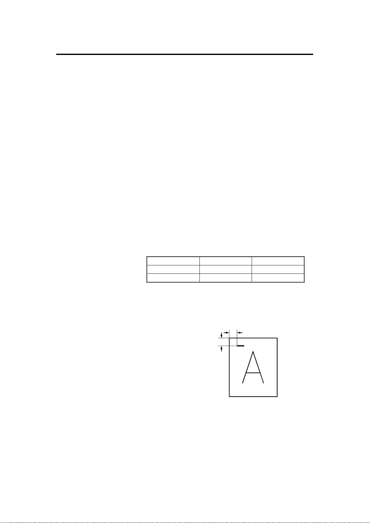
Staple Position:
a = b = 5 ± 2 mm
b
a
A591V500.wmf
Staple Time: Within 1.5 seconds/sta ple
Staple Replenishment : Cartridge exchange (5,00 0 pieces/cartridge)
1
Page 3

OVERALL MACHINE INFORMATION 31 July 1995
Power Source: 1st sorter: 100 V (from copier)
2nd sorter: 120 V (for U.S.A.)
220/230/240 V (for Europe)
Power Consumption: Maximum: 0.2 kW
Dimensions: (1st sorter only) 580 x 828 x 1063 mm
(22.8" x 32.6" x 41.8")
(1st and 2nd sorter) 1120 x 828 x 1063 mm
(44.1" x 32.6" x 41.8")
Weight: 1st sorter: 98 kg, 216 lb
2nd sorter: 90 kg, 198 lb
2
Page 4
31 July 1995 OVERALL MACHINE INFORMATION
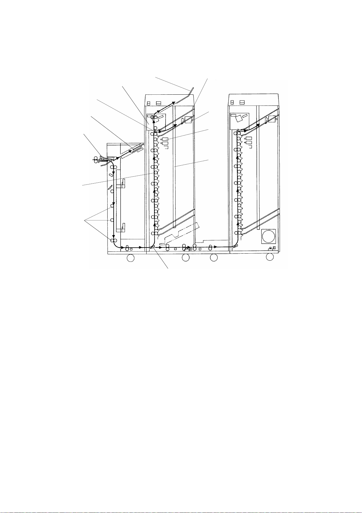
1.2 MECHANICAL COMPONENT LAYOUT
2
3
1
12
11
10
4
5
6
9
8
7
A591V501.img
1. Staple Unit
2. Proof Tray
3. Bins
4. Jogger
5. Bin Solenoids
6. Side Bar
7. Relay Gate
8. Diagonal Transport Rollers
9. Distribution Rollers
10. By-pass Tray Gate
11. By-pass Exit Tray
12. Bin Gate
3
Page 5
OVERALL MACHINE INFORMATION 31 July 1995
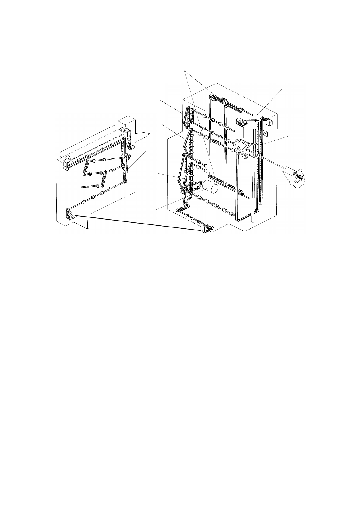
1.3 DRIVE LAYOUT
7
8
1
2
6
5
4
3
A591V502.img
1. Diagonal Transport Drive Belt
2. Bin Drive Belt (11th to 20th)
3. Main Motor
4. Jogger Unit Drive Belt
5. Staple Unit Drive Belt
6. Side Bar Drive Belt
7. Proof Tray Exit Roller Drive Belt
8. Bin Drive Belt (1st to 10th)
A591V503.img
4
Page 6

31 July 1995 OVERALL MACHINE INFORMATION
1.4 ELECTRICAL COMPONENT DESCRI PTION
Symbol Name Function Index No.
Motors
Main Drives the diagonal transport unit, horizontal
M1
M2
M3
M4
M5
M6
M7
M8
Staple Unit
Positioning
Jogger Unit
Positioning
Side bar Drives the side bar side to side according to
Grip Drives the gripper forward into the bin to grip
Staple Feeds the staples and drives the stapler
Jogger Drives the jogger arm to align the copy. (dc
By-pass Tray Gate Drives the by-pass tray gate up or down to
transport unit, and distribution unit through
timing belts.
Drives the staple unit up or down to the
appropriate bin. (dc stepper)
Drives the jogger unit up or down to the
appropriate bin. (dc stepper)
the paper size. (dc stepper)
the copies and bring them to the stapling
position. (dc brush)
hammer. (dc brush)
stepper)
switch the paper delivery tray.
22
5
9
1
12
15
18
36
Switches
SW1
SW2
SW3
Circuit Boards
PCB1 Main Controls overall sorter stapler functions. 31
PCB2
PCB3
PCB4
Solenoids
SOL1~20
SOL21
SOL22
SOL23
Front Door De-energize the main motor and cuts 24 V
line when the front door is open.
Vertical Transport
Door
Horizontal
Transport Door
DC Power Supply Convert ac voltage to 5 V dc and 24 V dc to
Bin Solenoid
Control 1
Bin Solenoid
Control 2
Bin Opens and closes the bin gate to direct the
Grip Opens and closes the bin gate to drive the
Pressure Release Releases pressure of the brake roller when
Relay Solenoid Turn the relay gate to transport the copy to
De-energize the main motor when the vertical
transport door is open.
Informs the main board if the cover is open.
supply power to all dc components.
Interfaces between the bin solenoids 1 ~ 10
and the main board.
Interfaces between the bin solenoids 11 ~ 20
and the main board.
copies into the appropriate bin.
grippers to grip copies on the bins.
the paper is fed lengthwise.
the 2nd sorter. 43
8
6
20
26
28
30
27
14
38
5
Page 7

OVERALL MACHINE INFORMATION 31 July 1995
Symbol Name Function Index No.
Sensors
S1
S2
S3 Proof Tray Exit Detects paper jams at the proof tray exit. 2
S4
S5
S6
S7
S8 Grip H.P. Detects if the gripper is in the home position. 11
S9
S10
S11 Side Bar H.P. Detects if the side bar is in the home position. 33
S12
S13
S14
S15 Paper Detect if copies are under the hammer. 7
S16 Staple End Detects if the staple is present. 16
S17
S18 Timing Supplies timing pulses to the main board. 29
S19
S20 Relay Sensor Detects paper jam at the relay unit. 42
Entrance Detects paper jams at the entrance of the
diagonal transport unit.
Registration Detects paper jams at the horizontal transport
unit.
Bin/Jam (LED) Detects if paper is in the bin.
Detects paper jams at the bin.
Bin/Jam (Photo Tr) Detects if paper is in the bin.
Detects paper jams at the bin.
Staple Unit H.P. Detects if the staple unit is in the home
position.
Jogger Unit H.P. Detects if the jogger unit is in the home
position.
Hammer H.P. Detects if the staple hammer is in the home
position.
Jogger H.P. Detects if the jogger arm is in the home
position.
Tray Gate H.P. Detects if the by-pass tray gate is in the home
position.
Tray Gate Upper
Position
Staple Unit
Position
Diagonal
Transport Door
Open
Relay Unit Cover
Open
Detects if the by-pass tray gate is in the upper
position.
Detects the position of the staple unit.
Detects if the diagonal transport door is open.
Detects if the relay unit cover is open.
37
21
3
19
4
10
13
17
34
35
32
39
41
Capacitor
C1 Main Motor Protects the PCB’s from induced current. 23
Noise Filter
NF1
Relay
RA1 Main Controls main power. 24
Transformer
TF1 2nd Sorter Steps down the line voltage to 100 Vac. 42
Noise Filter Removes electrical noise generated by the
copier and the sorter stapler.
6
25
Page 8

[F]
31 July 1995 OVERALL MACHINE INFORMATION
1.5 BASIC OPERATION
[C]
[G]
[I]
[A]
[B]
[H]
[D]
[E]
[J]
A591V501.img
Copies exiting the copie r ent er the sorter or the by-pass tra y [A] dep en din g
on the by-pass tray gate [B] posit ion . In normal operation, copies are sent to
the sorter, if paper jams occur in the sorter, the remaining papers in the
copier are fed to the by-pass tray.
If sort/stack mode is not selecte d, copies are delivered to the proof tra y [C]
through the diagonal transport unit [D], the horizontal transport unit [E], and
the distribution unit [F].
When sort/stack mode is select ed, copies are delivered to the bins [ G] in
order.
The copies in the bins are arranged by th e jog ge r arm [ H].
If staple mode is selected, when th e last pag e of the origin al is delive red to
the 1st bin, the staple unit [I] sta rts sta pling the copies in each bin.
The 1st sorter has capacity to hold 20 sorted copies.
If the 2nd sorter is installed next to the 1st sort er, an additional 20 sorted
copies can be sorted.
After the 20th copy is fed to the distribut ion unit of the 1st sorter, the relay
gate [J] moves to the uppe r posit ion and the 21st copy is transpo rted to the
2nd sorter. After the final copy of the designated number has passed unde r
the relay gate, the relay ga te mo ves do wn to transport copies to the bins of
the 1st sorter again.
7
Page 9
SECTIONAL DESCRIPTION 31 July 1995
2. SECTIONAL DESCRIPTION
2.1 PAPER DELIVERY SWI TCHING
[D]
[F]
[C]
[A]
A591D500.img
[F]
[E]
[B]
A591D501.img
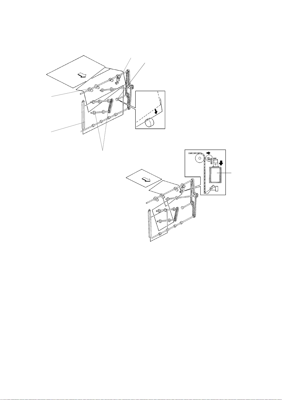
Depending on the by-pass t ray ga te [A] position, paper fed from th e cop ier
enters either the sort er or th e by-pass tray [B].
The by-pass tray gate is driven by the by-p ass tray gate motor [C]. Under
normal operating conditions, the by-pass tray gate is in the home posit ion
(H.P. sensor [D] is actuated) to delive r co pie s to the sort er. If a sorter paper
jam occurs, the gate rotate s on its sha ft [E] unt il the upper tray gate position
sensor [F] is actuated and stops.
8
Page 10
[A]
31 July 1995 SECTIONAL DESCRIPTION
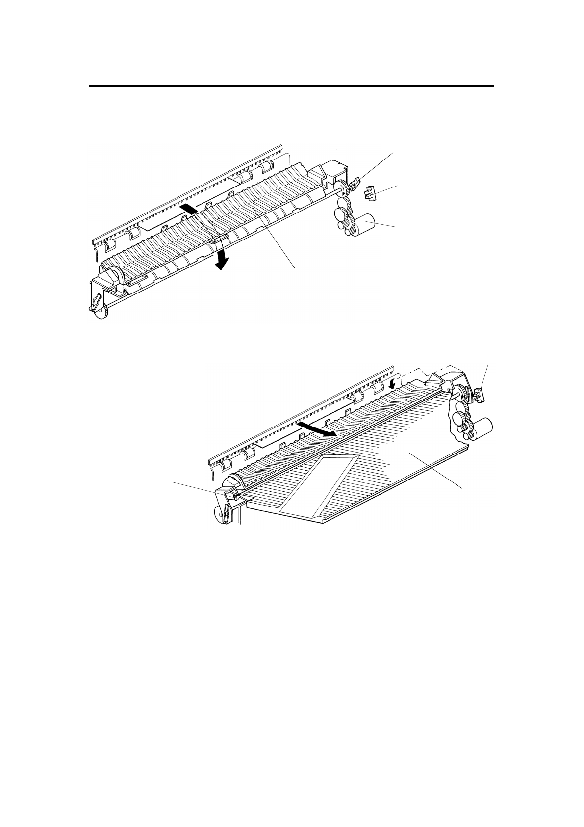
2.2 DIAGONAL TRANSPORT
[B]
[E]
[D]
A591D502.img
[C]
[E]
A591D503.img
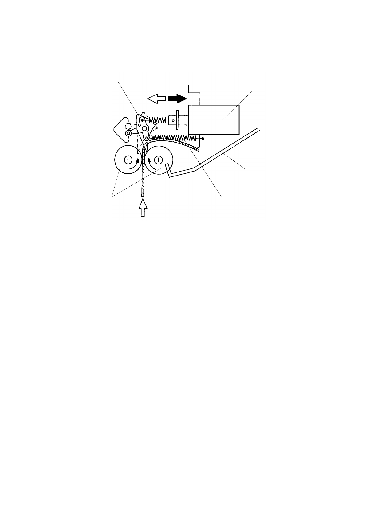
Paper entering the dia go na l t ran sport unit is transported do wn to the
horizontal transpo rt un it. The front side of the paper advances more than the
back side due to the front transport roller [A ] be ing larger than the back
rollers. This causes the paper to skew as it ente rs the diag onal transport unit.
This skew prevents the diagona l t ran sport guide [B] from catchin g the edge of
the copies.
The paper is then moved to the fron t by the diagonal transpo rt rollers [C].
Where it is aligned as it is guided by th e dia go na l t ran sport guide [B].
The brake roller [D] prevents the rear side of th e pa per f rom fa lling forward.
If the paper is traveling lengthwise, the pressure release solenoid [E] turns on
to prevent over skewing.
9
Page 11
[E]
SECTIONAL DESCRIPTION 31 July 1995
2.3 SORTING
[D]
[B]
[C][A]
A591D504.img
The distribution section has the distribution rollers [A], 20 bin gates, and 20
bin solenoids.
When a bin gate solenoid [B ] is off, the return spring [C] holds the bin gate [D]
out of the paper path, allowing the copies to pass to th e up per b in.
The appropriate bin gat e sole no id turns on and opens the bin gat e. The ot he r
solenoids are off. The copies go to the bin [E] throu gh the gate.
10
Page 12
[F]
31 July 1995 SECTIONAL DESCRIPTION
2.4 PAPER JOGGING
[B]
[A]
A591D505.img
[C]
[E]
[ D]
A591D506.img
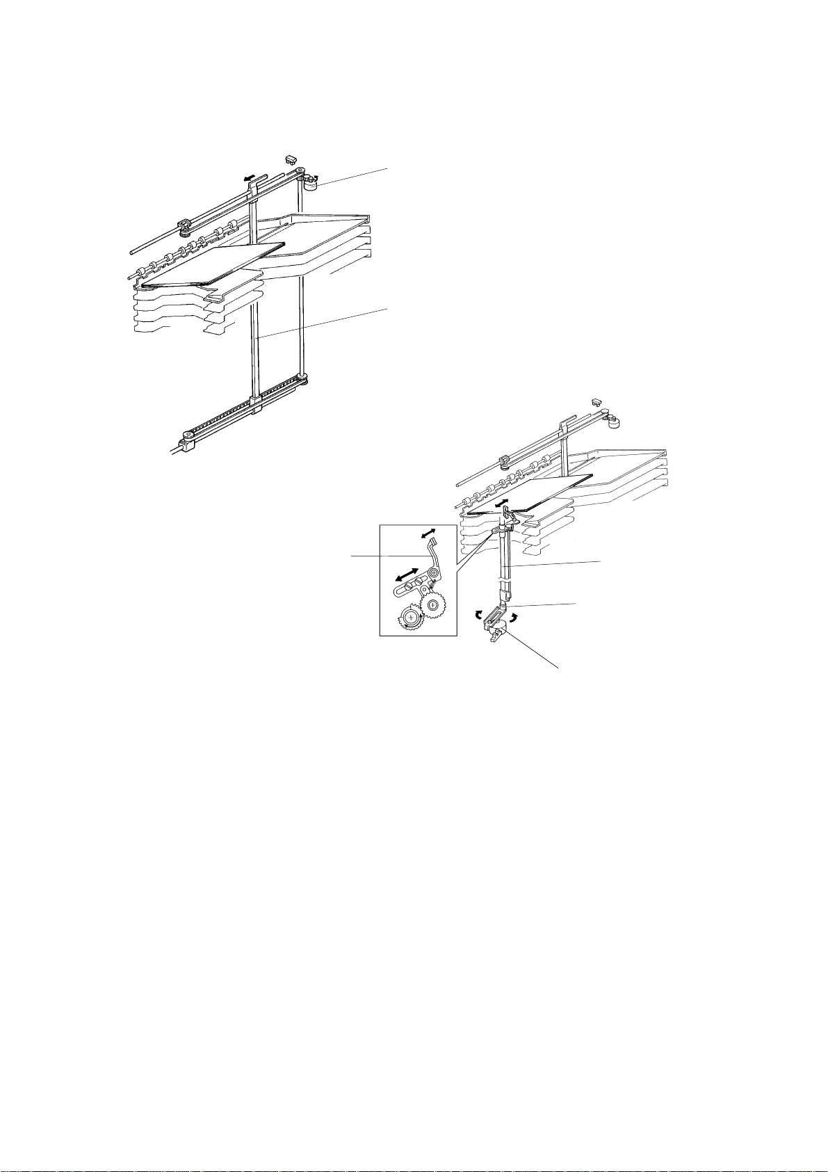
Ordinarily, the side bar [A] is in the home posit ion . It moves to within 10 mm
of the rear of the selected paper size. The side bar is driven by the side bar
motor [B] through the gears and a timing belt.
The jogger arm [C] home position is 10 mm in front of the paper.
After the paper passes the jam sen sor, the jogg er arm move s twice du e to
the forward and reverse rotation of the jogg er mot or [D]. Jogger arm
movement is controlled through the link [E] and jogger bar [F].
The reverse rotation of the jogger motor preven ts motor lock caused by an
overly stiff paper stack. Even if the ove rly stiff paper interferes with the jog ger
arm movement, the arm returns to its home position via the reverse rotation
of the jogger motor.
11
Page 13
[C]
SECTIONAL DESCRIPTION 31 July 1995
2.5 STAPLING
[A]
[E]
[D]
[B]
A591D507.img
2.5.1 Gripper
A591D508.img
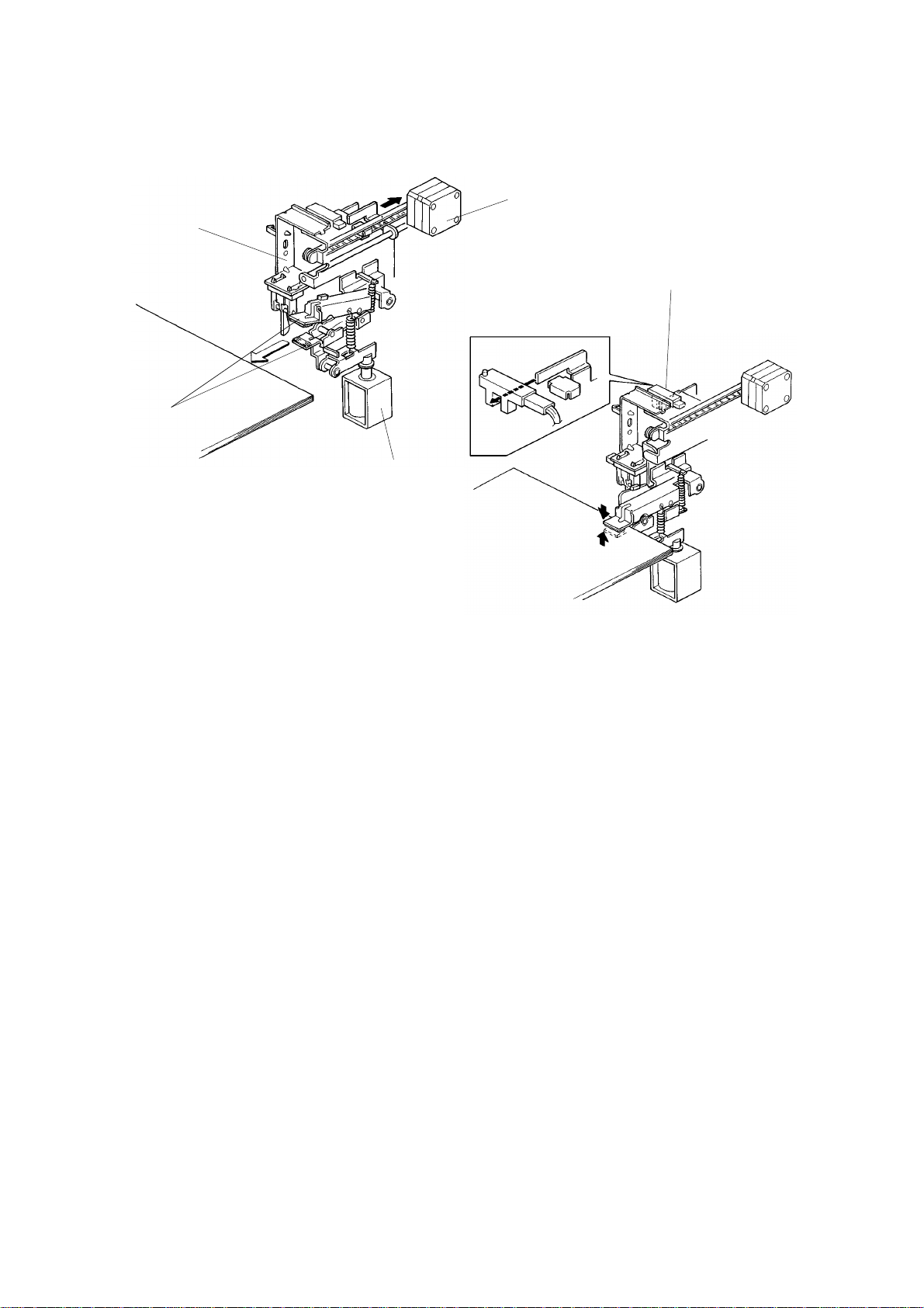
The grip unit [A] grips and moves the jogged paper to the staple position and
returns the stapled paper to the bin.
The grip solenoid [B] and grip moto r [ C] are built into the grip unit. The motor
moves the grippers [D] back and fo rth, and the solenoid [B ] con trols paper
clamping.
When the grippers reach the paper in the bin, the grip solen oid turns on and
the grippers grasp the pap er.
The lower gripper arm has a shorter stroke to pre ven t it from disturbing the
jogged pape r in t he b in .
Paper gripped by the grippers is moved by the grip motor into stapling
position.
Resetting the main PCB DIP SW1 01 -1 to 101 -4 adjusts the stapling position
(0.5 mm increments).
The stapled paper (held by the grip per arms t hro ug hout stap ling ) is ret urn ed
to its original position. The grip solenoid turns off to release the stapled
paper, and the gripper arms return to their original positio n.
The grip H.P. sensor [E] confirms th at the grip un it has retu rned to its home
position.
12
Page 14

31 July 1995 SECTIONAL DESCRIPTION
[A]
A591D509.img
[B]
[F]
[D]
[E]
A591D511.img
A591D510.img
2.5.2 Stapler
The paper sensor [A] preven ts sta pler operation when there is no paper in
position. Also, it detects staple error if the paper sen sor remains actuated
when the stapler finishes its operation.
The staple motor [B] drives the stapling mechanism and transporting of the
staples from the cartridge [C].
The hammer H.P. sensor [D] che cks if the staple ha mmer [E ] is in the home
position.
[C]
The staple end sensor [F] checks if staples are present.
13
Page 15

[B]
SECTIONAL DESCRIPTION 31 July 1995
2.6 JOGGER UNIT POS ITI ONING
[A]
A591D512.img
[C]
A591D514.img
A591D513.img
The jogger unit [A] vertical positio n is cont rolle d by the ste pp er mot or [B].
Depending on the rota tio n of the stepper motor [C], the jogger unit moves to
the appropriate bin.
When the main switch is turned on, the jogger unit will stop in its home
position. During sorter operation, the motor starts rotat ing when jogger
operation at any bin is comp let e. This lowers the jogger unit unt il it re ach es to
the next bin and then the motor stops.
When jogger operation for a designated numb er of copies is complete, the
motor rotates to raise th e jogger unit back to its home posit ion .
14
Page 16

[G]
[F]
31 July 1995 SECTIONAL DESCRIPTION
2.7 STAPLE UNIT POSITI ONI NG
[A]
[C]
[D]
A591D517.img
[H]
[E]
A591D515.img
[B]
A591D516.img
The staple unit [A] is hanging on the timing belt [B] . Due to the weig ht of this
staple unit, accurate po sitio nin g is e nsu red by using worm g ear [C] which
transmits the staple positioning motor [D] rotation to the timing belt.
The bracket [E] guiding the staple unit has notch es [F] wh ich th e staple unit
position sensor [G] senses.
Initially, the staple unit is beside the top bin. Wh en stap ling at th e first bin is
completed, the staple unit positioning mo to r [ D] en erg izes to move the staple
unit to the next bin where sta plin g is re pe at ed .
When stapling at the la st bin is comp let ed , th e motor [D] rotates to raise the
staple unit back to its home posit ion. The staple positionin g motor stops when
the staple unit home position sensor [H] is actuated.
Raising the staple unit requires more torq ue than lowe ring it . Thu s the moto r
speed when raising the staple unit will be approximately ha lf of the lowering
speed.
15
Page 17

[D]
[C]
SECTIONAL DESCRIPTION 31 July 1995
2.8 1ST AND 2ND SORTER CONNECTI ON
[B]
[A]
[E]
A591D518.img
When the 2nd sorter is connect ed, pa per mu st be re laye d fro m the 1st sort er
to the 2nd sorter. A relay solen oid [A] has been added to the 1st sorter for
this purpose.
A relay unit is also added to the 1st sorter to transport pape r to the 2nd sorte r.
The relay unit is driven by the 2nd sorter main mot or [B].
The relay sensor [C] detects paper jams at the relay un it.
The relay unit cover [D] is provided to enable removal of misfed papers.
The interrupter [E] detects if the cover [D] is open.
16
Page 18

31 July 1995 SECTIONAL DESCRIPTION
2.9 DOOR SWITCHES
A591D519.img
A591D520.img
Doors and guide plate s are pro vided to enable removal of misfed papers.
Each door has a safety switch to detect open ing and closing . These switches
also perform the jam reset fu nction.
17
Page 19

A591D521.wmf
Papers in
copier exit
SECTIONAL DESCRIPTION 31 July 1995
2.10 JAM DETECTION
2.10.1 Jam Detection Condition
The jam detection timing is dete rmine d by pulses fro m the timing senso r. The
diagram below illustrates the timing interval in which each sensor detects
paper jams in operation.
Entrance
Sensor
Registration
Sensor
Paper Exit Signal from Copier
Jam
Sensor
Exit
Sensor
Jam Detection Timing
Sorter Jam
By-pass Tray
Gate Motor
Tray Gate HP
Sensor
Tray Gate Upper
Position Sensor
Main Motor
*1
Stop Signal
from Copier
*1. Jam detection timing depends on the bin position
A591D522.wmf
Bin No. Pulses Bin No. Pulses Bin No. Pulses
proof 470 7 354 14 260
1 436 8 342 15 248
2 422 9 328 16 234
3 408 10 314 17 220
4 394 11 302 18 208
5 382 12 288 19 194
6 368 13 274 20 180
Staple failure is detected if the paper sensor is not de-energized after the
machine finishes returning the stapled paper to the bin.
18
Page 20

31 July 1995 SECTIONAL DESCRIPTION
2.10.2 Machine Operation in Jam Conditions
a. When a paper jam occurs in the copier, the sorte r stap ler sto ps af te r
delivering papers in the sorter to the appropriate bins.
b. When a paper jam occurs in the sorter stapler, the by-pass tray gate
motor energizes and papers in the copie r ar e delivered to the by-pass
tray.
c. When a staple failure is dete cted, the machine sto ps sta ple operation.
2.10.3 Jam Reset
a. If a paper jam occurs at the diagona l transport unit, the jam conditio n is
reset when the diagona l t ran sport door is closed after removing the
misfed paper.
b. If a paper jam occurs in the sorter, th e jam con dit ion is reset when the
vertical transport door or the horizont al tra nsp ort door is close d after
removing the misfed paper.
c. If a staple failure occu rs, th e jam condition is reset when th e sorter front
door is closed after removing the unstapled paper.
2.10.4 Jam Recovery
Copies on the bin are counted by the jam sensor.
When the start key is pressed af te r misfed paper is re move d, the machine
delivers the copies from the continu ance bin.
19
Page 21

INSTALLATION PROCEDURE 31 July 1995
3. INSTALLATION PROCEDURE
3.1 1ST SORTER STAPLER
3.1.1 Accessories
1. Tray Extension....................... .. .. .. .. .. .. .... .. .. .. .. ..1
2. Original Guard.................................................1
3. Upper Stay....................................................... 1
4. Lower Stay..................... .. .. .. .. .. .. .............. .. .. ....1
5. Harness Cover................... .......... .......... ..........1
6. Front Door........ .. .. .. .. .. .............. .. .. .............. .. .. ..1
7. Lower By-pass Tray................... .. .. .... .. .. .. .. .. .. ..1
8. Staple Cartridge......... .. .......... .. .................... .. ..1
9. Leveling Shoe.......................... .......... .......... ....2
10. M4 x 6 Screw .............. .......... .......... .......... ......9
11. M4 x 8 Screw with Star Washer............ .. .. .. .. ..2
12. Spacer......... .......... .......... .......... .......... .......... ..2
13. A2 Guide Plate
(European version only)................. .. .. .. .... .. .. .. ..1
20
Page 22

[C]
31 July 1995 INSTALLATION PROCEDURE
[D]
[A]
[A]
[C]
[B]
A591I500.img
[E]
A591I501.img
[F]
[J]
[J]
CAUTION:
N
[I]
[G]
[H]
A591I502.wmf
Unplug the copier power cord before starting the following procedure.
[C]
1. Remove the strips of filament tape [A] and remove the cushio n [B]
protecting the vertical transport door.
2. Remove the strips of filament tape [C] and remove th e cush ions [D]
protecting the bins.
3. Open the front door [E] and remo ve th e strip s of fila men t ta pe [F] fixing
the jogger unit.
4. Remove the shipping retainer [G] fixing the grip unit.
5. Remove the screw [H] fixing the staple unit.
6. Remove the rear cover [I] (6 screws).
7. Remove the three bracke ts [J] supp ort ing the vertica l t ran spo rt cover (2
screws each).
8. Reinstall the rear cover.
21
Page 23

INSTALLATION PROCEDURE 31 July 1995
[C]
[A]
[B]
A591I503.img
A591I504.img
9. Remove the right cover [ A] of th e copier (2 screws) and the plastic cap
[B]. Reinstall the righ t cover passing the interf ace harness [C]
(3 connectors and 1 ground wire) thro ug h the hole of the lower righ t
cover.
10. Fix the upper and lower stays [D] (5 screws) to enab le fixin g of the
diagonal transport unit.
[D]
22
Page 24

31 July 1995 INSTALLATION PROCEDURE
[H]
[F]
[E]
[C]
[G]
A591I505.img
11. Open the diagonal transport door [A] and remove the front cover [B]
(2 screws) of the diagonal transport unit .
12. Set the connecto rs of the interface harness [C] from the copier to the
diagonal transport unit [D].
[D]
[A]
[B]
13. Fix the ground line [E] to the diagon al tra nsport unit (M4 x 8 screw with a
star washer).
14 Hook the diagonal transport unit on the upper stay [F]. Then fix the unit to
the lower stay [G] (2 screws and 2 spacers).
15. Install the lower by-pass tra y [H].
23
Page 25

INSTALLATION PROCEDURE 31 July 1995
[A]
[B]
[C]
[E]
[F]
[G]
[D]
[H]
A591I506.img
16. Stick the original guard [A] ont o the uppe r cover [B] of the 1st sorter.
NOTE: S tick it 14 0 mm from the end of the cover.
17. Install the tray extension [C].
18. Join the 1st sorter to the diagon al tra nsp ort unit, pressing the 1st sorter
until the two latches [D] lock toget her .
19. Connect the harne ss conn ect ors [E] and the optical fibe r ca ble [F].
20. Set the timing belt [G ] an d ho ok th e tension spring [H].
24
Page 26

31 July 1995 INSTALLATION PROCEDURE
[B]
[D]
[C] [A]
A591I507.img
[E]
[F]
21. Install the harness cover [ A] (2 M4 x 6 screws).
[H]
[G]
A591I508.img
22. Fix the ground wire [B] onto the diagona l transport unit (M4 x 8 with star
washer).
23. Install the front cove r [C] of the diag onal transport unit (2 screws) and set
the front door [D].
24. Open the front door of the sorter, remove the staple cover [E], and set th e
staple cartridge [F].
25. Put the two leveling shoes [G] under the feet. Adjust the sorter height by
securing down feet so that the sorter is parallel to the copier.
26. Install the A2 guide plate [H] (Euro pe an version only).
27. Turn on the main switch of the copier and test the operation of the sorter
stapler.
NOTE: The stapler will not staple for the first 10 or so copies until th e
first staple from the cartridge reache s the proper po sitio n for
stapling.
25
Page 27

INSTALLATION PROCEDURE 31 July 1995
3.2 2ND SORTER STAPLER
3.2.1 Accessories
1. Relay Unit........................................................1
2. Optical Fiber Cable................ .. .................... .. ..1
3. Tray Extension....................... .. .. .. .. .. .. .... .. .. .. .. ..1
4. Interface Board ................................................1
5. Joint Bracket.................. .......... .......... .......... ....1
6. Harness Cover Bracket......... .. .......... .. ............1
7. Motor Cover........... .......... .......... .......... .......... ..1
8. Bin Bottom Bracket..........................................1
9. Relay Gate Solen oid.... .......... .......... .......... ......1
10. Staple Cartridge......... .. .......... .. .................... .. ..1
11. Leveling Shoe.......................... .......... .......... ....2
12. Bushing ........... .......... .......... .......... .......... ........1
13. Relay Connector.................. .......... .. .......... .. ....1
14. Decal.......... .. ............ ...................... ............ ......1
15. M4 x 6 Philips Pan Head Screw........ .. .......... ..2
16. M4 x 6 Truss Head Screw................... .. .. .. .. .. ..1
17. M4 x 6 Screw with Washer...................... .. .. ....2
18. M4 x 8 Screw with Star Washer............ .. .. .. .. ..1
19. M4 x 6 Screw with Spring Washer ..................3
20. M4 x 8 Double Washer Screw........... .. ............1
21. Flat Head Screw........ .................... .. .......... .. ....1
26
Page 28

[E]
[F]
[C]
31 July 1995 INSTALLATION PROCEDURE
[B]
[C]
[A]
[D]
A591I509.img
A591I501.img
[J]
[I]
[J]
[G]
CAUTION:
N
[H]
A591I502.wmf
Unplug the copier power cord before starting the following procedure.
1. Remove the strip of filame nt tap e [A ] fixing the relay unit cover [B ].
2. Remove the strips of filament tape [C] and remove th e cush ions [D]
protecting the bins.
3. Open the front door [E], remove the strips of filament tape [F] fixing the
jogger unit.
4. Remove the shipping retainer [G] fixing the grip unit.
5. Remove the screw [H] fixing the staple unit.
6. Remove the rear cover [I] (6 screws).
7. Remove the three bracke ts [J] supp ort ing the vertica l t ran spo rt cover (2
screws each).
27
Page 29

[L]
INSTALLATION PROCEDURE 31 July 1995
[B]
[A]
[C]
[D]
A591I510.img
[G]
[E]
[I]
[J]
[H]
A591I512.img
[M]
[K]
A591I511.img
8. Remove the rear cover of the 1st sorter (6 screws).
9. Remove the lower right cover [A] (2 screws), motor co ver [B ] (2 screws),
and 2 studs [C] from the 1st sorter. Insta ll t hem o n the 2nd sort er.
(Set the studs into th e ho les [D] of the lower right cover.)
[F]
10. Hook the spring [E] of th e relay gate solenoid [F] packed with the 2nd
sorter to the relay gate lever [G] of the 1st sorter and fix th e rela y gat e
solenoid (2 screws with washer and 1 connect or).
11. Set the interf ace board [H] packed with t he 2nd sorter on the CN200 of
the 1st sorter main board [I] so that the notch of the interface board is up.
12. Remove the front harn ess cove r [J] (3 screws) an d inn er ha rne ss co ver
[K] (2 screws). Connect the opt ical fiber cable [L] packed with the 2nd
sorter to the interface board and run the cab le as shown in the illustration.
13. Install the relay con nector [M] packed with the 2n d sort er to the end of the
optical fiber cable [L].
14. Reinstall the inner harness cover [K].
28
Page 30

[E]
[F]
31 July 1995 INSTALLATION PROCEDURE
[C]
[A]
[B]
[D]
A591I513.img
[I]
[H]
[G]
[K]
[J]
A591I514.img
15. Install the motor cover [A] (M4 x 6 pan hea d screw [B] an d M4 x 6 screw
with spring washer [C]) and the bin bottom bracke t [D] (truss head screw
[E] and double washer screw [F] ) bot h pa cked wit h th e 2n d sorter to the
1st sorter.
16. Remove the front cover [G] (1 screw) and th e rear cover [H] (2 scre w) of
the relay unit.
17. Install the joint bracket [I] packed with the 2nd sorter (flat head screw [J])
on the relay unit [K].
18. Install the relay unit to the 1st sort er (2 M4 x 6 screws with spring washer).
19. Reinstall the rear cover [H] of the relay un it and the rear cover of the 1st
sorter.
29
Page 31

[F]
INSTALLATION PROCEDURE 31 July 1995
[A]
[H]
[B]
[D]
[C]
[G]
[E]
[I]
A591I515.img
[A]
A591I516.img
20. Remove the front cover [A] of the horizo nt al tra nsport unit (2 screws).
21. Join the 2nd sorter to th e rela y unit and set the timing belt [B ]. Th en hoo k
the spring [C] of the te nsio n pu lley bracket.
22. Install the harness cover b racke t [D] (1 scre w, M4 x 6) packe d with the
2nd sorter to the relay unit.
23. Connect the three of th e five connectors [E] from t he 2nd sorter.
24. Fix the ground line [F] from the 2nd sorter to the relay unit (M4 x 8 with a
star washer).
25. Pass the harness throu gh the cuto ut of the bracket [D] and inst all the
bushing [G] packed with the 2nd sorter.
26. Install the front cove r [A] of th e horizontal transport unit (1 screw).
CAUTION
N
If the 1st sorter height adjustment is requir ed again (this adjustment
was done during the 1st sorter installati on), do it before step 27.
Otherwise, the harness may be caught in the threads of leveli ng
adjuster.
27. Install the front ha rness cover [H] and the front cove r [I] of the horizontal
transport unit.
30
Page 32

31 July 1995 INSTALLATION PROCEDURE
[B]
[A]
A591I517.img
[C]
[D]
A591I518.img
[E]
A591I519.img
28. European version mach ine s only
If the voltage of electrical power supply from wall outlets is 220 V or 240
V, change the voltage as follows:
a) Disconnect the input lin e [A ] from the 230 V connector.
b) Connect the input line to the approp riat e volt ag e (22 0 V or 240 V).
29. Reinstall the rear cover.
30. Open the front door of the sorter, remove the staple cover [B], and set th e
staple cartridge [C].
31. Put the two leveling shoes [D] under the feet . Ad just the sorter height by
securing down feet so that the sorter is parallel to the copier.
CAUTION
N
If the 1st sorter height adjustment is requir ed again (this adjustment
was done during the 1st sorter installati on), do it before step 27.
Otherwise, the harness may be caught in the threads of leveli ng
adjuster.
32. Stick the decal [E] on th e left rear cover of the copier b esid e the power
cord.
33. Turn on the main switch of the copier and test the operation of the sorter
stapler.
NOTE: The stapler will not be stapling for the first 10 or so copies un til
the first staple comes to the proper position fro m the cartrid ge .
31
Page 33

SERVICE TABLES 31 July 1995
4. SERVICE TABLES
4.1 TEST POINT TABLE (Main Board)
Number Function
TP100 GND
TP101 5 V
TP102 24 V
TP103 Lower Staple Unit Trigger (SP Mode)
4.2 LED AND VARIABLE RESISTOR TABLE (Ma in Board)
LED No. VR No. Function
100 100 Adjusts jam sensor sensitivity
101 101 Adjusts bin sensor sensitivity
4.3 FUSE TABLE
Number Specification Location
Fuse 100 125 V 5 A Main Board
Fuse 1 125 V 5 A PSU
32
Page 34

31 July 1995 SERVICE TABLES
4.4 DIP SW TABLE
DIP SW100 (MODE) SP mode
1 2 3 4 Function
0 0 0 0 Initial Normal Setting
1 0 0 0 Sorter Free Run
0 1 0 0 Staple Unit Free Run
1 1 0 0 Sorter & Staple Unit Free Run
0 0 1 0 Lower Staple Unit
0 0 0 1 Bin/Jam Sensor Adjustment
0: OFF 1: ON
1. "Sorter Free Run", "Staple Unit Free Run" or "Sorter & Staple Unit Free
Run" starts operation when the DIP swit che s are set as shown in the
table.
2. "Lower Staple Unit" starts operation when TP103 is short- circuited to
TP100 (GND), after setting DIP SW1 00 -3 to 1.
3. Bin/Jam sensor can be adjusted by VR100 and VR 101 after setting DIP
SW100-4 to 1.
Operation
1. Sorter Free Run
1) Main motor turns on.
2) Side bar moves to the A4 position.
3) By-pass tray gate moves to the upper position.
4) Pressure release solenoid is ene rgize d fo r 2 .4 seconds.
5) Bin solenoids turn on at the 1st bin continuing in order down to the
20th bin.
6) Jogger moves at each bin.
7) Machine stops operation for one second and then rep ea ts th e ab ove
operation from 1).
2. Staple Unit Free Run
The sorter stapler repeats the sta ple ope rat ion in order from the 1st bin to
the 20th bin.
3. Sorter and Staple Unit Free Run
The sorter stapler works as if 20 sets of 2 A4 papers are pre sen t an d
sorted in auto staple mode.
4. Lower Staple Unit
Staple unit lowers until it reach es to the 20th bin and stop s.
33
Page 35

(–)
(+)
SERVICE TABLES 31 July 1995
DIP SW101 (STAPLE) Staple positio n adjust ment
1234 Staple Position
000–Standard Value
1 0 0 0/1 0.5 mm shifted
0 1 0 0/1 1.0 mm shifted
1 1 0 0/1 1.5 mm shifted
0 0 1 0/1 2.0 mm shifted
1 0 1 0/1 2.5 mm shifted
0 1 1 0/1 3.0 mm shifted
1 1 1 0/1 3.5 mm shifted
–––0(+) Direction (farther from the edge)
–––1(–) Direction (closer to the edge)
0: OFF 1: ON –: Not concerned
DIP SW101-1, 101-2, and 101-3 det ermin es th e len gt h the sta ple posit ion is
shifted.
DIP SW101-4 determines the shif t dire ction up or down.
34
Page 36

31 July 1995 SERVICE TABLES
4.5 MAINTENANCE TABLE
Items Standard Procedure Tools
Rollers Clean the rollers if they are soiled. A cloth dampened with alcohol
Bins Clean the rollers if they are soiled. A cloth dampened with alcohol
Sensors Clean the rollers if they are soiled. A cloth dampened with alcohol
Bushings Lubricate the bushings if they make noise. Launa-40 oil or equivalent
Gears Lubricate the gears if they make noise. Grease G-501
Worm Gear Lubricate the worm gear if it makes noise. Mobil temp 78
35
Page 37

REPLACEMENT AND ADJUSTMENT 31 July 1995
5. REPLACEMENT AND ADJUSTMENT
5.1 BIN/JAM SENSOR ADJ USTME N T
A591R500.img
NOTE: This adjustment should be performed when the main board or the
bin/jam sensor is replaced.
1. Remove the rear cover.
2. Confirm that there is no paper on the bins.
3. Turn on the DIP SW100-4 on th e main board.
4. Turn the VR100 and VR101 so that the LED100 and LED101 are at the
ON/OFF threshold (just tu rns of f).
5. Turn off the DIP SW100-4.
36
Page 38

31 July 1995 REPLACEMENT AND ADJUSTMENT
5.2 STAPLE POSITION ADJUSTMENT
[A]
Y
X
[B]
[C]
[G]
[F]
[D]
A591R501.img
[H]
[E]
A591R502.img
A591R503.img
NOTE: This adjustment should be performed when the main board or staple
unit is replaced.
X Direction
1. Check the position of th e staple [A] on the copy pap er.
2. Remove the upper cover [B] (4 screws),op en the vertica l t ran spo rt do or
[C] and remove the left front cove r [ D] (4 screws).
3. Lower the staple unit [E] by manually turning the timin g belt [F] of the
staple unit positioning motor in the direction of the arrow.
4. Remove the staple unit upper cove r [ G] (1 screw).
5. Loosen the two screws [H] and adjust the staple unit position.
6. Retighten the screws [H].
Y Direction
1. Check the position of th e staple [A] on the copy pap er.
2. Remove the rear cover.
3. Adjust the staple position by setting the DIP SW101.
37
Page 39

REPLACEMENT AND ADJUSTMENT 31 July 1995
5.3 SIDE BAR ADJUSTMENT
[A]
[B]
[D]
[C]
A591R504.img
[E]
1. Remove the upper cover [A ] an d th e rear cover [B].
2. Manually move the side bar [C] towards the front side of the bin side bar
slot [D], by turning the side bar motor manually.
3. Confirm that the side bar is parallel and contacts both the 1st and 20th bin
side bar slots front side.
4. If improper conta ct is observed between the 1st and 20th bin, remove the
timing belt clamp [E] and reposition th e side bar po sitio n.
38
Page 40

[H]
[K]
[L]
31 July 1995 REPLACEMENT AND ADJUSTMENT
5.4 BELT TENSION ADJUSTMENT
[A]
A591R505.img
[a]
[B]
[A]
[C]
[D]
[E]
[F]
[G]
[L]
1. Detach the diagonal transport unit from
the copier, remove the rear cover of the
diagonal transport unit, and adjust the belt
[A] tension with tightener [a].
Standard [A]: 8 mm deflection at
100 ± 30 g pressure
[J]
[I]
A591R508.img
[B]
[C]
[D]
[G]
A591R506.img
[e]
[b]
[c]
[d]
[E]
[f]
A591R507.img
[F]
2. Remove the rear cover of th e distribution
unit and adjust the belt [B], [C], [D], [E],
[F], [G] tension with tightener [b], [c], [d],
[e], [f], [g].
<Standard>
[B]: 5 mm deflection at 80 ± 30 g pressure
[C]: 5 mm deflection at 140 ± 40 g pressure
[D]: 5 mm deflection at 100 ± 50 g pressure
[E]: 5 mm deflection at 100 ± 50 g pressure
[F]: The distance between the belt and the
bottom plate is 0.7 to 2.0 mm
[G]: 5 mm deflection at 100 ± 50 g pressure
39
Page 41

REPLACEMENT AND ADJUSTMENT 31 July 1995
[j]
[I]
[H]
[h]
A591R509.img
[I]
A591R510.img
3. Remove the upper cove r o f th e dist ribution
unit and adjust the belt [H] tension with the
tightener [L].
Standard [H]: 5 mm deflection at
170 ± 30 g pressure
4. Remove the upper cover and right cover
then adjust the belt [I] tension with the
tightener [i].
Standard [I]: 30 mm deflection at
200 ± 30 g pressure
[k]
[l]
[J]
[K]
A591R511.img
A591R512.img
[L]
A591R513.img
5. Remove the upper cover and adjust the
belt [J] tension with the mo to r position
bracket [j].
Standard [J]: 5 mm deflection at
200 ± 30 g pressure
6. Remove the upper cover and adjust the
belt [K] tension with the motor position
bracket [k].
Standard [K]: 5 mm deflection at
150 ± 50 g pressure
7. Remove the upper cover and adjust the
belt [L] tension with the tightener [l].
Standard [L]: 10 mm deflection at
200 ± 30 g pressure
40
Page 42

[E]
31 July 1995 REPLACEMENT AND ADJUSTMENT
5.5 STAPLE ELEVATOR UNIT REMOV A L
[D]
[A]
[C]
[B]
A591R514.img
A591R515.img
[I]
[G]
[J]
[K]
[F]
A591R516.img
A591R517.img
1. Remove the upper cover, the fron t do or, the right front cover.
2. Remove the staple unit [A] (1 screw).
3. Remove the two screws fixing the flat cable [B] and disconnect the three
connectors [C].
4. Lower the staple eleva tor unit by turning the timing belt [D]of the staple
unit positioning motor manually until it reach es to the lower limit.
5. Remove the idle pulley [E] (2 screws).
6. Count the number of the timing belt [F] pit che s tha t sticko ut of the fixin g
plates [G]. Then remove the two fixing plat es (2 screws ea ch).
7. Remove the front doo r hinge [H] (1 screw) and the elevator guide bar
fixing bracket [I] (1 screw).
8. Slide out the elevat or gu ide bar [J] and remove the eleva to r unit [K].
NOTE: When reassembling the machine , fix th e be lt with the fixing plate
as it was confirmed in step 6.
[H]
41
Page 43

REPLACEMENT AND ADJUSTMENT 31 July 1995
5.6 BIN REMOVAL
[C]
[D]
[A]
[E]
A591R518.img
[B]
[G]
[F]
A591R519.img
1. Remove the upper cover [A ], the rear cover [B], the front door [C] the right
front cover [D], and th e lowe r rig ht cover [E].
2. Remove off the side bar [F] from the side bar holder [G] and remove it.
3. Remove the appropria te bin.
42
Page 44

31 July 1995 REPLACEMENT AND ADJUSTMENT
5.7 BIN/JAM SENSOR RE MOV A L
[A]
[B]
A591R520.img
[C]
[E]
[D]
A591R521.img
Upper Bin/Jam Sensor
1. Remove the upper cover (4 screws).
2. Remove the bin/jam sensor b racke t [A ] (1 screw).
3. Replace the upper bin/jam se nso r [B] (1 screw).
4. Adjust the sensor sensitivity by turning VR1 00 and 101 on the main board.
Lower Bin/Jam Sensor
1. Remove the motor cover [C] (2 screws) an d th e ha rne ss cover [D] (2
screws).
2. Remove the bottom 5 bin s.
3. Replace the lower bin/jam sensor [E] (1 screw).
4. Adjust the sensor sensitivity by turning VR1 00 and 101 on the main board.
43
Page 45

[H]
REPLACEMENT AND ADJUSTMENT 31 July 1995
5.8 SORTER DETACHMENT
[F]
[D]
[E]
[G]
[A]
[C]
[B]
A591R522.img
1. Remove the front cover [A] of the diag on al tra nsp ort unit (2 screws) and
remove the front door [B] .
2. Remove the harness cover [C] (2 screws).
3. Disconnect the 5 connecto rs [D], the fiber optic cable [E] and remove the
screw [F] fixing the ground line.
4. Take the timing belt [G] off the pulleys.
5. Press the lock lever [H] to the allow direction and detach the sorte r f rom
the copier.
44
 Loading...