

Page 1

20-BIN SORTER STAPLER
(Machine Code: A554)
Page 2

13th January 1995 SPECIFICATIONS
1. SPECIFICATIONS
Paper Size for Bins: Sort or stack mode:
Maximum: A3, 11" x 17"
Minimum: A5, 51/2" x 81/2" lengthwise
Staple mode:
Maximum: A3, 11" x 17"
Minimum: B5, 81/2" x 11"
Paper Weight for Bins: Sort mode:
52 - 93 g/m2, 14 - 24 lb
Stack mode:
64 - 93 g/m2, 17 - 24 lb
Staple mode:
52 - 80 g/m2, 14 - 21 lb
Number of Bins: 20 bins + proof tray
Stapler
20-bin Sorter
Bin Capacity: Sort mode: 30 sheets (A4, 81/2" x 11")
15 sheets (A3, 11" x 17")
Stack mode: 15 sheets
Proof tray - 100 sheets
(52 – 80 g/m2, 14 – 21 lb)
- 50 sheets
(81 – 128 g/m2, 22 – 34 lb)
- 30 sheets
(129 – 157 g/m2, 35 – 42 lb)
Stapler Capacity: A4, 81/2" x 11" or smaller: 2 – 20 copies
B4, 81/2" x 14" or larger: 2 – 10 copies
Stapling Position:
(Horizontal)
a
b
(Diagonal)
a
b
a = b
= 6 ± 3 mm
= 0.24" ± 0.12"
1
a = 16 ± 3 mm
= 0.63" ± 0.12"
b = 10 ± 3 mm
= 0.39" ± 0.12"
Page 3

SPECIFICATIONS 13th January 1995
Staple Replenishment: Cartridge exchange
(3,000 staples/cartridge)
Power Source: DC 24V, 5V (form the copier)
Power Consumption: 34 W
Dimensions:
(W x D x H)
412 x 600 x 690 mm
(16.2" x 23.6" x 27.1")
Weight: About 25 kg, 55.1 lb
(Main Frame: 22 kg, 48.5 lb
Mounting Frame: 3 kg, 6.6 lb)
2
Page 4

13th January 1995 COMPONENT LAYOUT
2. COMPONENT LAYOUT
2.1 MECHANICAL COMPONENT LAYOUT
1
11
12
10
13
2
3
4
5
6
7
8
Stapler
20-bin Sorter
1. Proof Tray
2. Proof Tray Exit Rollers
3. Vertical Transport Rollers
4. Turn Gate
5. Bin Transport Belt
6. Bin Transport Roller
7. Bin Exit Roller
9
8. Stapler
9. Grip Assembly
10. Bin Support Block
11. Bins
12. Suppor t Bin
13. Jogger Bar
3
Page 5
10
COMPONENT LAYOUT 13th January 1995
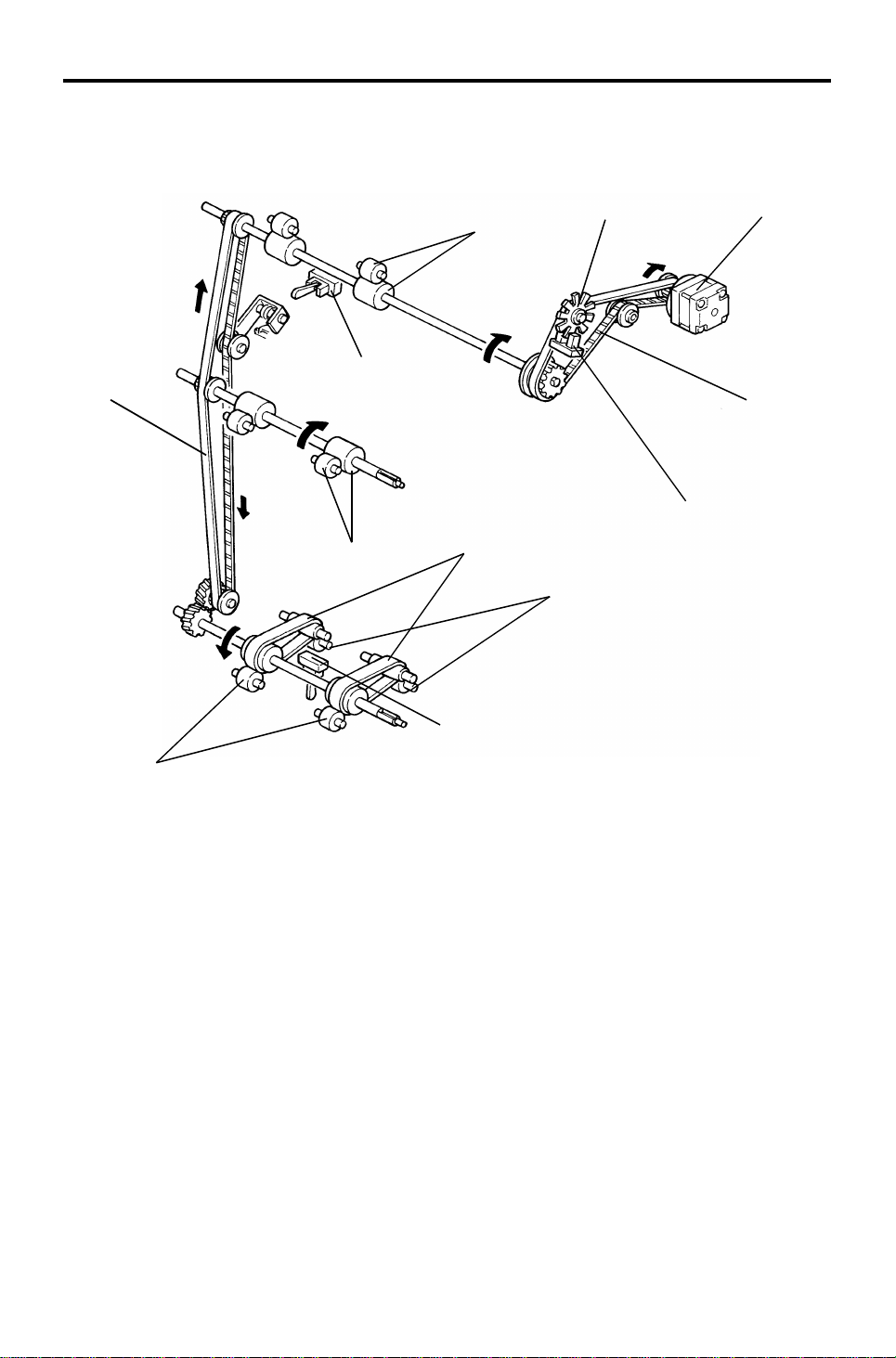
2.2 DRIVE LAYOUT
22
21
20
19
18
17
16
15
14
4. Roller Drive Motor Pulley
23
1
2
13
12
11. Bin Lift Motor Pulley
3
4
5
6
7
8
9
11
3. Rear Roller Drive Belt
2. Proof Tray Exit Roller
Pulley (Rear)
(Proof Tray Exit Roller)
19. Proof Tray Exit Roller
Pulley (Front)
18. Front Roller Drive Belt
17. Vertical Transport
Drive Pulley
15. Bin Transport Drive Gear
14. Bin Transport Belts
8. Bin Lift Drive Belt
7. Bin Lift Gears
6. Bin Lift Gear/Pulley
12. Rear Bin Lift Wire
9. Rear Bin Support
Block
10. Jogger Motor Pulley
13. Lower Jogger Drive Belt
21. Bin Drive Shaft
20. Front Bin Lift
Pulley
16. Front Bin Lift
Wire
22. Front Bin
Support Block
5. Jogger Drive Shaft
1. Upper Jogger
Drive Belt
23. Jogger Bar
4
Page 6

13th January 1995 COMPONENT LAYOUT
2.3 ELECTRICAL COMPONENT DESCRI P TI ON
Refer to the electrical compone nt layou t on the reverse side of the Poin t to
Point diagram (on waterproof paper).
Symbol Name Function
Motors
M1 Bin Lift
M2 Jogger
M3 Grip
M4 Stapler Feeds the staples and drives the stapler hammer. 12
M5 Roller Drive
Circuit Board
PCB1 Main Control Controls all sorter stapler functions. 18
Solenoid
SOL 1 Turn Gate
Sensors
S1 Bin Lift Timing -1
S2 Bin Lift Timing -2
S3 Jogger H.P.
S4 Paper
S5 Bin (LED)
S6 Bin (Photo transistor)
S7 Grip H.P.
S8 Bin H.P.
S9 Bin Exit Detects paper jams at the bin exit area. 5
S10 Proof Tray Exit Detects paper jams at the proof tray exit area. 4
S11 Roller Drive Timing
Lifts and lowers the bins via a belt, gears, and
wires.
Drives the jogger bar to jog the copies against
the front side plate.
Drives the grip assembly into the bin to grip the
copies and bring them to the stapling position.
Drives the proof tray exit, vertical transport
rollers, and bin transport belts.
Opens and closes the turn gate to direct the
copies into either the proof tray or the bins.
Monitors the rotation of the bin lift motor by
detecting the timing disk.
Controls the stop timing of the bin lift motor so
that the bin lift timing sensor no. 1 can detect the
timing disk properly.
Detects whether the jogger bar is at the home
position.
Detects whether there are any copies under the
hammer.
Detects whether there is any paper in the bins
(light emitting element).
Detects whether there is any paper in the bins
(light receiving element).
Detects whether the grip assembly is at the
home position.
Detects whether all the bins are in the down
(home) position.
Monitors the roller drive motor speed by
detecting the timing disk.
Index
No.
23
20
13
1
Stapler
20-bin Sorter
6
24
25
19
8
3
17
16
15
2
5
Page 7

COMPONENT LAYOUT 13th January 1995
Symbol Name Function
Switches
SW1 Upper Lift Limit
SW2 Wire Tension
SW3 Front Door Cuts the 24 Vdc line when the front door is open. 14
SW4 Sorter Stapler Set
SW5 Staple End Detects the staple end condition. 10
SW6 Staple Guide Detects whether the staple guide plate is closed. 9
SW7 Staple H.P.
The bin lift motor stops when this switch detects
the upper limit position of the bins.
The bin lift motor stops when this switch detects
the lower limit position of the bins through the bin
lift wire tension.
Cuts the 24 Vdc line when the sorter stapler unit
is open.
Detects whether the staple hammer is at the
home position.
Index
No.
22
21
7
11
6
Page 8
13th January 1995 BASIC OPERATION
3. BASIC OPERATION
3.1 NORMAL MODE AND SORT/STACK MODE
[E]
[C]
[G]
[F]
[B]
Stapler
20-bin Sorter
[A]
[D]
Copies [A] exiting the copier pass t hro ug h the entra nce guide plates to the
turn gate area. The turn gate [B] will sen d copies either to the proof tray or to
the bins, depending on the mode.
- Normal mode -
In this mode, copies pass from the turn gate sectio n to the proo f tray.
When the copier signals the S/S CPU to start the motor, the roller drive motor
[C] rotates all the rollers in the S/S pap er path . At the same time , th e tu rn
gate solenoid [D] is energized and the turn gat e tu rns clockwise . The turn
gate directs copies to the proof tra y [E] through the vertical transport and
proof tray exit rollers [F and G].
7
Page 9
BASIC OPERATION 13th January 1995
- Sort/Stack mode -
[C]
[G]
[H]
[A]
[I]
[B]
[D]
[E]
[F]
In this mode, copies pass from the turn gate section to the bins.
The turn gate solen oid [A] stays off and th e turn gate [B] stays up when t he
S/S roller drive motor [C] starts rot at ing. The turn gate directs copies
downward and the bin transport belt [D] exits copies t o th e bin through the bin
transport and bin exit rollers [E and F].
The jogger bar [G] th en moves th e copy towards the front and jo gs it against
the front side plate to square the copies.
The bin lift motor [H] turn s on whe n th is jogg ing operation is almost finished
and advances the bin one ste p up along the bin cam track [I]. The bin lif t
motor stops at the proper time to posit ion the next bin at the bin exit area.
This bin movement is done fo r each co py in sort mode and for the final copy
of each original in stack mode.
The up and down movement of th e bins in both sort and stack modes is the
same as for other moving bin type sorters.
8
Page 10
Figure 4
13th January 1995 BASIC OPERATION
3.2 STAPLE MODE
[A]
Figure 1 Figure 2
[B]
Figure 3
When the final set of copies has been jogged in sort mode, the staple unit
staples the stacked co pie s as f ollo ws:
Figure 1:
If the final copy is fed out to a bin other than the first one, all the bins lower to
the home position (the first bin is positioned at the bin exit area ). The jogger
bar [A] moves towards th e fro nt to jog the copies stacked in th e first bin. Then
it stops 15 mm away from the side edge of the pa pe r.
Figure 2:
The bins move one step up to place the first bin at the stap ling posit ion.
Stapler
20-bin Sorter
Figure 3:
The grippers [B] move forward, an d grip the copies.
Figure 4:
The grippers bring the copies up unde rne at h the sta pler. At the same time,
the jogger bar jogs the cop ies stacked in the second bin to pre pa re for the
next stapling operation . The n th e jog ger bar returns to the position 15 mm
away from the side edge of th e pa pe r.
9
Page 11

BASIC OPERATION 13th January 1995
Figure 5
Figure 6
Figure 5:
The stapler staples th e cop ies.
Figure 6:
The copies are pushed back int o the bin. Then the grippe rs ope n an d ret urn
to the home position.
The bins move one step up for the next stapling opera tio n.
When the final set of copies is stapled, the bins lower and stop when the final
bin that was used just before the entire stapling operation is positione d at the
bin exit.
There are two staple modes.
1) Automatic stapling:
In ADF/ARDF mode, when the user selects sta ple mode before pressing
the Start key, the copies will be delivered to each bin and stapled
automatically.
2) Manual stapling:
In sort mode, after copies are sort ed in the bins, the copie s will be stap led
when the user presses the sta ple key after copying. In stack mode,
manual stapling is impossible.
10
Page 12

[B]
13th January 1995 TURN GATE SECTION
4. TURN GATE SECTION
[B]
[E]
[E]
[C]
[A]
[A]
[D]
The turn gate directs copies to the pro of tray or to the bins depe nding on the
mode selected.
Stapler
20-bin Sorter
In the normal mode, the turn gat e sole no id [A] turns on together with the
roller drive motor when the copier signals the S/S CPU to sta rt th e motor. The
turn gate [B] rotates clockwise to dire ct cop ies up ward [C] th rou gh the vertical
transport section to th e proof tray. The turn gate solen oid stays on during the
copy cycles, and turns off when the proo f tra y exit sensor detects the trailing
edge of the last copy and the S/S CPU receives the signal from the copier to
stop the motor.
In the sort, stack, or staple mode, the turn gate solenoid stays off to keep the
turn gate up so that copies are direct ed down ward [D] to the bin transport
section.
The solenoid lever [E] is bent at a righ t an gle to en sure tha t the lever moves
only if the solenoid switches fro m on to off, or from off to on.
11
Page 13
[F]
ROLLER DRIVE AND CONTROL 13th January 1995
5. ROLLER DRIVE AND CONTROL
[G]
[E]
[I]
[C]
[J]
[B]
[D]
[K]
[A]
[H]
[L]
The roller drive motor (a stepper motor) [A ] drive s the proo f tra y exit rolle rs
[B], vertical transport rollers [C] , bin transport belts [D], bin tran sport rollers
[E], and bin exit rollers [F] via the front and rear roller drive be lts [G and H],
pulleys, and gears, as shown above.
The roller drive motor turns on when the copier signals the S/S CPU to switch
the motor on. When the proof tra y exit sen sor [I] (in the normal mode) or the
bin exit sensor [J] (in the sort/stack/staple mode) detects the trailing edge of
the final copy, the S/S CPU info rms the copie r t hro ugh th e fib er cab le an d the
interface PCB. The n the copier signals the S/S to stop the roller drive motor.
The S/S CPU monitors the roller drive motor speed by counting pulse s from
the timing disc [K] through the roller drive timing sensor [L ].
12
Page 14

13th January 1995 ROLLER DRIVE AND CONTROL
To feed copies out as fast as possible, th e S/ S CPU con tro ls t wo mot or
rotation speeds.
The normal speed depends on the copier’s p ape r tra nsp ort speed. The S/S’s
paper transport speed is almost the same as bu t sligh tly fa ster than the
copier’s.
In the normal mode, the roller drive motor changes the paper tra nsp ort speed
from normal to high (500 mm/s, fixed) when the S/S CPU receives the pape r
exit signal from the copier. The roller drive motor changes the paper transp ort
speed from high to normal 100 milliseconds aft er th e pro of tray exit senso r
detects the trailing edge of the copy.
In the sort/stack/sta ple mo de, the roller drive motor also changes the paper
transport speed from normal to high and the n from high to normal. The timin g
is the same as in the normal mode, bu t the bin exit sensor is used to dete ct
the trailing edge instead of the pro of tray exit sensor. The high speed is
almost double the normal speed, and it changes depending on the paper size
(900, 960, or 1 ,0 00 mm/ seco nd).
Stapler
20-bin Sorter
13
Page 15
[M]
BIN DRIVE AND CONTROL 13th January 1995
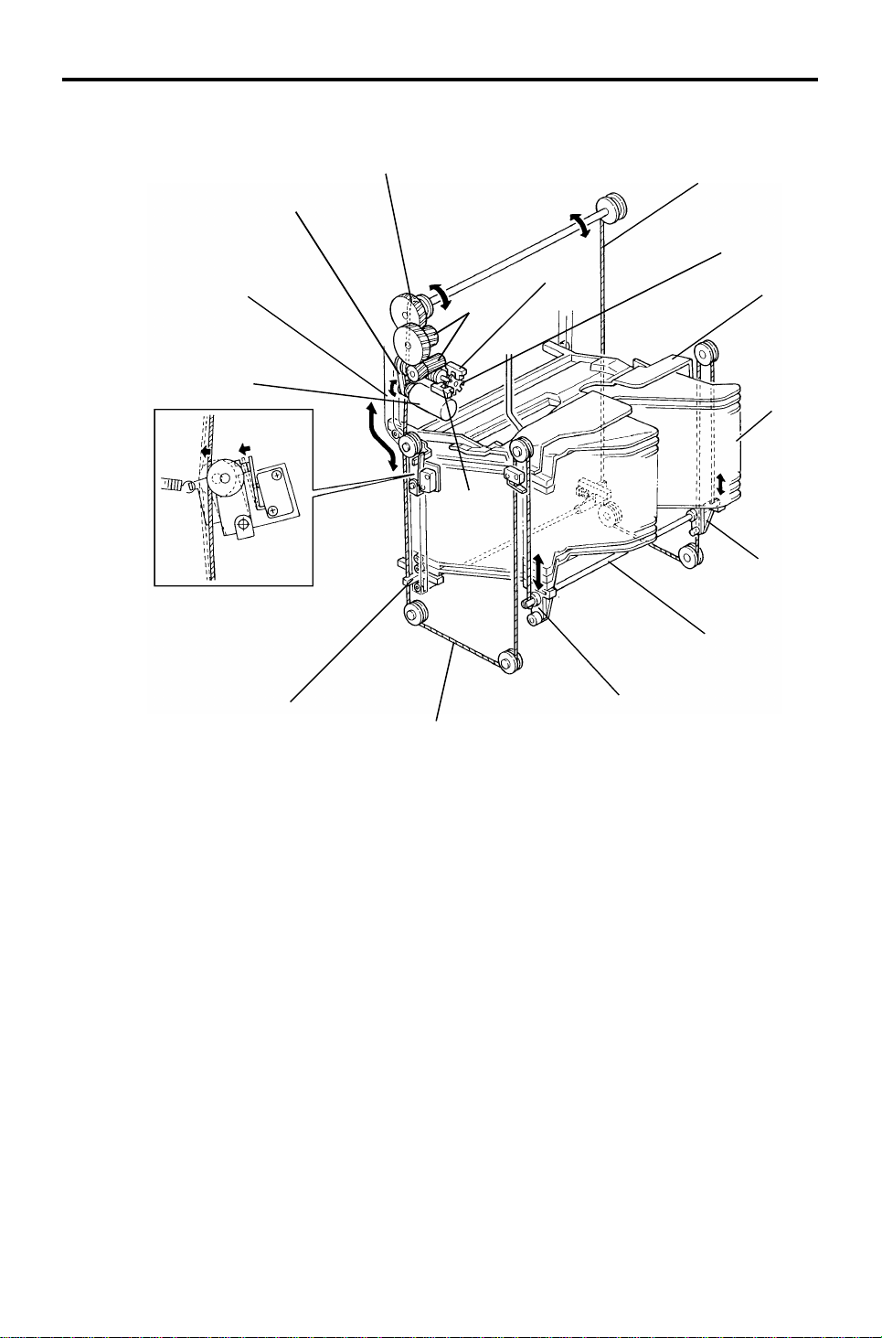
6. BIN DRIVE AND CONTROL
[G]
[J]
[F]
[I]
[H]
[L]
[E]
[K]
[B]
[A]
[C]
[D]
[C]
[E]
All the 20 bins [A] and the support bin [B] are piled up on the bin support
blocks [C]. The front and rea r bin support blocks are connecte d by th e bin lift
shafts [D], the ends of which are fixed to the bin lif t wires [E ] as shown. The
bin lift motor [F] (dc motor) drives the bin lift wires thro ug h the bin lif t drive
belt [G], bin lift gears [H], an d th e bin lift gear/pulley [I]. Then the bins are
driven up and down along the front an d rea r bin cam tracks [J].
The S/S CPU controls the amount of bin lift motor rotation by monitorin g the
pulses from the timing disc [K] th rough the bin lift timing sensors 1 and 2 [L
and M]. Bin lift timing sensor 1 (blue con ne cto r) is use d for coun tin g th e
timing pulses. Bin lift timing sensor 2 (white connector) is used to determin e
the motor stop timing so that the edge of the timing disc slots is not
positioned at timing sensor 1.
[C]
14
Page 16

13th January 1995 BIN DRIVE AND CONTROL
[A]
[G]
[D]
[E]
Stapler
20-bin Sorter
[F]
[B]
[C]
If the bin lift motor [A] fails t o sto p the bin s at the hig he st po sitio n, the re ar
end of the left bin lift shaft [B] activate s the upper lift limit switch [C] (which is
a normally-closed type) to open the 24 Vdc line to th e bin lift mot or.
The front right bin suppo rt blo ck [D] ha s an act uator on its underside. When
all the bins are lowered and the first bin is positioned at the bin exit are a, the
actuator activates the bin home position sensor [E] and the bin lift motor turns
off.
If the bin lift motor fails to stop lowering the bins at the bin home positio n, the
rear bin lift wire [F] slackens. The n th e wire tension switch [G] (which is a
normally-open type) is deactivat ed , which ope ns th e 24 Vdc line to the bin lift
motor.
15
Page 17
BIN DRIVE AND CONTROL 13th January 1995
[A]
[B]
[E]
[C]
[D]
Fig. 1
Fig. 2
[F]
Fig. 3 Fig. 4
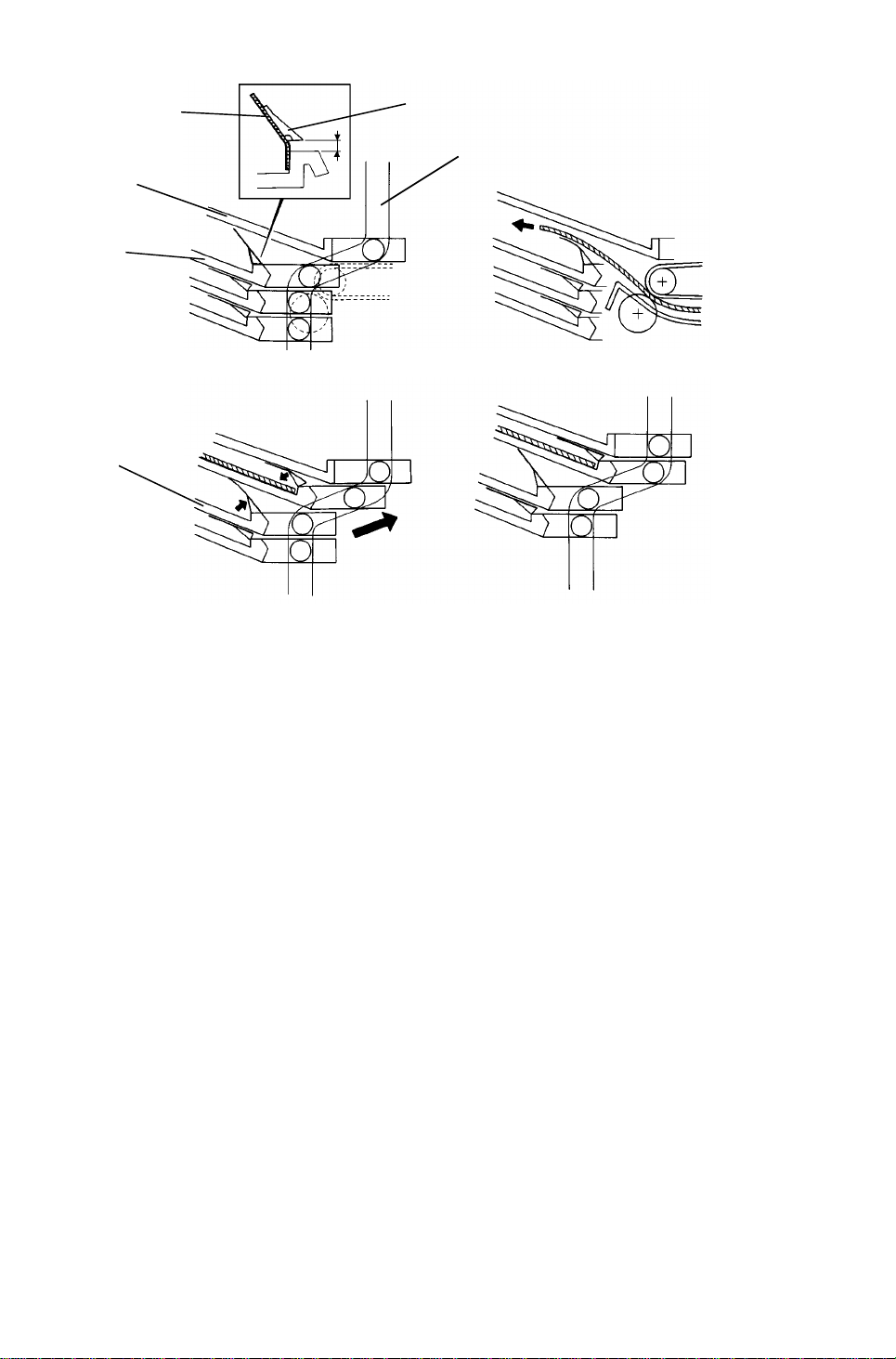
An end fence mylar [A] is attached to each bin entra nce and an end fence
block [B] is stuck on the mylar. These are att ached with two-sided tape, as
shown in figure 1. There is a twisted spring at the rear end of the bin entrance
to raise the end fence block and mylar. Whe n the bin s are at the bin ho me
position, the support bin [C] and th e first bin [D] are positio ne d at the bend in
the bin cam track [E] as shown. The supp ort and first bins have a space
between them so that the end fence mylar can fully rise until the end fence
block stops it.
The space between the support and first bin s is at the bin entra nce section
as shown in figure 2. Since the end fence mylar is t hin , the copy exits to the
first bin over the mylar. The steep angle of the bin helps th e exit ed copy slide
back due to its own weight und er the mylar against the bin entrance.
When the bins move up along the bend of the bin cam track, the end fence
mylar and block of the first bin are pushed down by th e sup port bin, and
those of the second bin [F] rise as shown in figure 3.
When the bin lift motor stops, the first and second bins are positioned as
shown in figure 4. The lowe red end fence mylar helps to prevent the copy in
the first bin from moving out of the jogged posit ion . The end fence mylar an d
block of the second bin are ready to receive the next copy.
16
Page 18

13th January 1995 JOGGER SECTION
7. JOGGER SECTION
[D]
[F]
[A]
[E]
[C]
[B]
When the Start key is pressed in the sort , sta ck, or staple mode, the copier
sends the paper size information to the sorter st apler. When a copy enters
the sorter stapler entrance , th e jog ge r bar [A ] stays at the home position
which is detected by the jogger home position sensor [B].
At the appropriate time (depending on the selected paper size) after the
trailing edge of the copy is detected by the bin exit sen sor, the jogg er mot or
[C] (a stepper motor) rotates forward and in reverse to move the jogger bar
via the upper and lower jogger drive belt s [D and E]. As the copy is f ed out
into the bin at the cent er, the jogger bar moves the cop y all the way t o th e
front, and pushes th e pa pe r sid e edge by 5 mm (0. 2") aga inst the front side
plate [F]. Then the jogger bar moves back to the posit ion wh ich mat ches the
paper width. Shortly after that, the jogger bar retu rns to its home position.
This jogger bar movement is perfo rmed for ea ch cop y to squ are the copy
stack.
Stapler
20-bin Sorter
In the automatic or manu al sta ple modes, the jogger bar also moves to
ensure that the stacked copies are squared bef ore stap ling. For how the
jogger moves, see "Basic Operat ion - St aple Mode".
17
Page 19

JOGGER SECTION 13th January 1995
- Jogger off conditions -
1. Under the following conditions, the jogger bar does not jog after a copy is
delivered to the bin.
• If paper is loaded in a bin by hand while the sort/sta ck or stap le
mode is selected.
• If the selected paper size does not match the stapling specification s.
• If copies of different width are delivered to the bins.
2. If there is paper in a bin before the main switch is turned on, the
sort/stack mode is disabled when the sorter key is pressed.
18
Page 20

Fig. 2
13th January 1995 GRIP ASSEMBLY
8. GRIP ASSEMBLY
[K]
[A]
[E]
[B]
[D]
Fig. 1
Figure 1:
The grip assembly consists of th e gripper guide bracket [A] , th e gripper
assembly [B], and the bin sid e pla te [C]. The major component s o f th e grip pe r
assembly are the grip motor [D] (a stepper mot or), dual cam plat e [E ], grip
home position sensor [F], grippers [G], and grip cam follower [H].
[I]
[C]
[G]
[J]
[H]
[F]
[L]
Fig. 3
Stapler
20-bin Sorter
When the copier main switch is turned on, the grip motor ro tate s forwa rd
and/or reverses to position the whole gripper assembly at the home position.
The home position is detected by the grip home position sensor and the
sensor actuator on the dual cam plate.
Figure 2:
When the bin lift motor stops during the automatic or ma nual sta pling cycle,
the grip motor starts rotating . As th e dual cam plate turns counter-clockwise,
the cam groove [I] and the pin [J] on the gripper guide bracke t move the
whole gripper assembly alo ng the gripp er gu ide ro d [K ] into the bin.
Figure 3:
When the high lobe of the grip cam [L] (t he small ca m on th e du al cam pla te )
pushes up the grip cam follower, the grippers close to grip the cop ies that are
stacked in the bin.
19
Page 21

[B]
Fig. 6
GRIP ASSEMBLY 13th January 1995
Fig. 4
[A]
[C]
[C]
Fig. 5
Figure 4:
As the dual cam plate rotates further, the cam groove and the pin move the
whole gripper assembly with the gripp ed copies back to the stapling position.
Then the grip motor stops.
Figure 5 and 6:
The upper gripper has a proje ctio n [A] for hooking the bin side plat e [B ].
When the gripper moves into the bin, the proje ctio n moves over the bin side
plate. When the gripp ers close , the projection hooks the bin side plat e.
Therefore, the gripp ers bring the stacked copies in to the stap ler together with
the bin side plate.
When the grippers move to the sta plin g po sitio n, the S/S CPU checks th e
paper sensor [C] to see if there is any pape r the re or not. If the paper sensor
is activated, the stapler motor starts rotating and the copies are stap led .
When the stapler motor stops, the grip mot or starts rotating in reverse. The n
the gripper assembly brings back the stapled copies into the bin, the grippers
open, and the gripper assembly returns to the home position.
20
Page 22

[I]
13th January 1995 STAPLER
9. STAPLER
[B]
[D]
[C]
[A]
[G]
[E]
[F]
[B]
[H]
Stapler
20-bin Sorter
[H]
[J]
In automatic or manual staplin g mod e, the stapler motor [A] rotates when the
grip motor stops rotat ing aft er the grippers bring the stacke d copies to the
stapling position.
The staple gear [B] rotate s coun te rclockwise , an d the pin on the gear rot at es
the staple arm [C] counterclockwise, then clockwise. The rat che t [D] lowers
and rises to rotate the ratchet whe el [E] counterclockwise. Then the st aple
feed rollers [F] turn via gears to feed a staple shee t to the hamme r.
While both the front and rear staple arms rotate cou nt erclo ckwise, the
hammer [G] lowers. At the same time, the stap le cam pla te [H] lifts the
clincher [I]. The hammer and the clin che r stap le th e cop ies. Then , while the
staple arms rotate clockwise, the hammer rises and the clincher lowers.
When the staple home position switch (a normally-closed typ e) [J] is
deactivated, the stapler mot or sto ps.
21
Page 23

STAPLER 13th January 1995
[B]
[E]
[A]
[C]
[D]
When all the staple sheet s are fed out of the staple cartridge, a notch cut out
of the staple pressure plate [A] deactivate s the stap le end switch (a norma llyclosed type) [B]. The S/S CP U send s the stap le en d signal to the copier. Afte r
the stapling job is completed for all the bins, the Add Staples indicator lights
on the copier operatio n pa ne l and the Read y indicator turns off whenever the
staple mode is selected.
Staple jams are easily cleared by opening the staple guide plate [C]. The
staple guide switch (a normally-closed type) [D] detects whether the staple
guide plate is closed or open . When the S/S front door and S/S unit it self are
closed with the staple guide plate open, the Add Sta ple s in dica tor lights on
the copier operation panel.
The stapler can be swung on the stapler support bracket [E ] an d it ha s tw o
lock positions. One is for horizon tal stapling and the other is for diagona l
stapling (at 25 degrees).
22
Page 24

13th January 1995 STAPLER
- Stapler inoperative conditions -
1. Under the following conditions, the staple mode is inoperative when the
staple key on the operation panel is pressed.
• If there is paper in a bin before the main switch is turned on.
• If the selected paper size does not match the stap ling specif ications.
2. Under the following conditions, the staple mode is canceled.
• If paper is loaded into a bin by hand while stap le mod e is se lect ed .
• If only one copy is delivered to th e bin.
• If the jogger operat ion has not been performed.
• If some already-stapled copies are present in the bin s.
• If the number of sheets delivered to th e bin exceeds the stapler
capacity.
Stapler capacity: 2 to 20 sheets for A4, B5, and 81/2 " x 11"
2 to 10 sheets for B4, A3, 81/2" x 14", and
11" x 17"
The stapler capacity can be increa sed by 5 for both pap er size typ es
by changing the SP mode setting fo r the Stapling Limit. (If this is
done, the staplin g fu nction is not guaranteed.)
Stapler
20-bin Sorter
3. Under the following conditions, manual stapling mod e in sort mode is
inoperative.
• If paper is loaded into a bin by hand while sort mode is selected.
• If the paper size in the bin does not match the sta plin g spe cifications.
• If only one copy is delivered to th e bin.
• If copies of different width are delivered to the bin.
• If some already-stapled copies are present in the bin.
23
Page 25

JAM DETECTION AND STAPLER ERROR 13th January 1995
10. JAM DETECTION AND STAPLER ERROR
10.1 SORTER JAMS
- Normal Mode -
Copier Paper
Exit Sensor
Proof Tray
Exit Sensor
- Sort/Stack/Staple
Mode -
Copier Paper
Exit Sensor
Bin Exit
Sensor
[A]
[B]
The sorter stapler main contro l board dete cts pape r jams in the sorte r stapler,
or between the sorter staple r and the copie r. To de te ct jams, the S/S CPU
uses the paper exit on/off signal f rom th e cop ier, and the proof tray exit
sensor [A] (in normal mode) or the bin exit sensor [B] (in sort/stack/staple
mode).
Jam check timing in normal and in sort/st ack/ sta ple modes is shown above.
There are two time scales: one in seco nds and milliseconds, and one in
pulses. The pulses are the timin g pu lses fro m t he roller drive timing sensor.
Since the paper transport speed of the sorter stapler (this is the normal spe ed
mode) depends on that of the copier, the sorter stapler ca nnot operate on a
fixed time scale. Therefore , to match the sorter stapler speed to th e cop ier’s,
the copier sends a signal to the S/S CPU; this controls the normal speed of
the roller drive motor (the speed in high spe ed mode neve r change s) and this
generates the pulse rate.
24
Page 26

13th January 1995 JAM DETECTION AND STAPLER ERROR
If the proof tray exit sensor or the bin exit sensor is actua te d when the sorter
stapler unit or the front door is opened and closed, or when the main switch is
turned on, a sorter jam signal is sent to the copier.
Sorter jam conditions are rese t by op en ing and clo sing the sorter stapler unit
or the front door after clearing the jammed paper.
When an abnormal condition of the main motor, bin lift mot or, or jogger motor
is detected for the first time, the copier’s operation panel will indicate a sorter
jam. When the abnormal condition is detected for the second time, the S/ S
CPU sends an error signal to the copier. The copier’s opera tio n panel will
indicate a service call code.
10.2 STAPLER ERROR
The sorter stapler main control board detects a stapler error when th e
following conditions are detected. The copier’s operation pan el will indica te a
sorter jam, and stapling will stop in the se case s.
Stapler
20-bin Sorter
• If the paper sensor is actua ted when the sorter stapler or the front
door is opened or closed, or when the main switch is turned on.
• If the paper sensor is actua te d when the grip assembly retu rns to the
home position after the stapling operation .
• The first time an abnormal condition of the stapler motor or grip
motor is detected.
The second time an abnormal condition is detected, the copier’s
operation panel will indicate a service call code.
25
Page 27

Turn Gate
Solenoid
Interface
Motor
OFF signal
TIMING CHARTS 13th January 1995
11. TIMING CHARTS
Timing Chart 1: Normal Mode (A4 sideways, 5 copi es)
Paper exit signal
from copier
Roller Drive
Motor
Proof Tray
Exit Sensor
Normal
mode
signal
Motor ON
signal
Normal speed
High speed
SS paper
exit signal
Timing Chart 2: Sort Mode (A4 sideways, 2 copies for 5 bins)
Interface
Motor ON
signal
Paper exit signal from copier
Motor OFF
signal
Roller
Drive
Motor
Bin Lift
Motor
Jogger
Motor
Bin Exit
Sensor
Bin Number
Paper Size
A3 350 ms 190 ms 900
B4 350 ms 160 ms 900
A4 sideways 205 ms 375 ms 960
A4 lengthwise 610 ms 0 ms 900
B5 sideways 150 ms 370 ms 900
B5 lengthwise 230 ms 0 ms 900
11" x 17" 295 ms 130 ms 900
1/2" x 14" 675 ms 90 ms 900
8
1/2" x 11" sideways 130 ms 265 ms 960
8
1/2" x 11" lengthwise 625 ms 0 ms 900
8
Bin Lift Motor
ON Timing
Jogger Motor
ON Timing
High Speed
(mm/s)
26
Page 28

Interface
Bin Lift Motor
Jogger Motor
Stapler Motor
13th January 1995 TIMING CHARTS
Timing Chart 3: Stapling (A4 side wa ys , 2 copi es for 5 bins)
Grip Motor
Staple ON
signal
1 staple cycle
Staple count
signal
Job completion
signal
Returns to
H.P.
Stapler
20-bin Sorter
27
Page 29

ACCESSORY CHECK 13th January 1995
12. ACCESSORY CHECK
Check the quantity and cond itio n of the accessories in the box as listed
below:
1. Proof Tray............................................................................1
2. Staple Cartridge ..................................................................1
3. Staple Position Decal..........................................................1
4. Stepped Screw ...................................................................1
5. Philips Truss Head Screw - M4 x 6.....................................1
6. Philips Pan Head Screw - M4 x 14......................................4
7. New Equipment Condition Report
(–17 machines only) ...........................................................1
8. Installation Procedure .........................................................1
28
Page 30

13th January 1995 INSTALLATION PROCEDURE
13. INSTALLATION PROCEDURE
[A]
Stapler
20-bin Sorter
[B]
Make sure to follow the instructions below when unpacking and
installing the sorter stapler.
• Grasp the stay [A] when unpacking the sorter stapler.
• Never hold the guide plate [B] when unpackin g the sorter stapler.
If you hold the guide plate, it migh t be dama ge d and this will
cause paper jams.
• Avoid catching the guide plate [B] on anything when installing
the sorter stapler.
29
Page 31

INSTALLATION PROCEDURE 13th January 1995
[A]
[B]
NOTE: (1) Keep the shipping retainers after installing the machine. They will
be reused if the machine will be tran sported to an another
location in the future.
(2) Proper reinstallat ion of th e ship pin g retainers is required in order
to avoid any transport damage.
(3) A sorter adapter (A568) is req uire d to install this sorter stapler in
the A157/A159/A160/A 16 1/A1 62 copie rs. Be fo re inst alling this
sorter stapler, please in sta ll the sorte r a dapt er in th e cop ier.
CAUTION
!
Unplug the copier power cord before starting the fol low ing proc edur e.
1. Remove the strips of tape and the shipping ret ain ers [A].
2. Open the front door [B] and remove the strips of tape from the staple unit
and close the front door.
30
Page 32

13th January 1995 INSTALLATION PROCEDURE
[A]
[B]
[C]
[E]
[D]
3. Remove the two plastic caps [A] from the copier left cover with nippers.
4. Remove the rear cover [B] of the sorter staple r.
5. Release the lock lever [C] of the sorter stapler and un ho ok the sorter
stapler mounting frame [D] while releasing the stopper [E] as shown.
Stapler
20-bin Sorter
31
Page 33

[M]
INSTALLATION PROCEDURE 13th January 1995
[D]
[C]
[A]
[F]
[E]
[B]
[G]
[J][I]
[L]
[H]
[K]
[N]
6. Remove the M4 x 8 round head screws from the left cover of the copier
(A153/A155/A156 copiers: 2 screws [A], A157/A159/A160/A161 /A1 62
copiers: 3 screws [A] and [B]).
7. Mount the sorter stapler mounting frame [C] on the copier as shown
(4 – M4 x 14 screws).
NOTE: When hooking the sorter stapler mounting frame on the left side
of the copier, make sure th at the posit ioning hooks [D] on the
frame are properly inserted in th e po sitio nin g ho les [E ] in the
copier.
8. Remove the junction gate [F] (1 snap ring) before installin g th e sorter
stapler. This prevent s the junction gate from damaging the guide plate of
the sorter stapler mounting frame.
9. Install the sorter stapler [G] on the sort er sta pler mounting frame (2 hinge
pins at the rear).
NOTE: First, lift the sorter stapler ont o the sup po rt pla te [H], ope nin g the
sorter stapler about 30 degrees. Then, insert the upper stud [I]
into the upper hinge ho le [J] . Finally, insert the lower stud [K] into
the lower hinge hole [L].
10. Remount the junction gate [F] (1 snap ring).
11. Connect the link lever [M] to th e sort er sta pler using the stepped screw
[N], then close the sorter stapler.
32
Page 34

13th January 1995 INSTALLATION PROCEDURE
[B]
[A]
[C]
12. Connect the connectors [A] to the sockets on th e rea r o f th e copier.
13. Remount the rear cover [B] (4 screws).
Stapler
20-bin Sorter
14. Mount the proof tray [C] (1 screw) a s shown .
33
Page 35

INSTALLATION PROCEDURE 13th January 1995
[C]
[B]
[A]
[D]
[E]
[C]
15. Open the front door o f th e sorter stapler and swing the sta ple unit [A] up.
16. Remove the green plastic clip [B ] fro m t he st aple cartridge [C] and correct
the position of the sta ple sheet [D] to make it flush with the other sheets
in the cartridge.
17. Install the cartridge in the stapler while holding the staple unit.
18. Put the staple unit back in its original position, close th e sorter stapler
front door, and plug in the copier.
19. Attach the staple positio n decal [E ] to the ARDF as shown .
20. Turn on the copier main switch and test the operat ion of the sorter stapler.
NOTE: The stapler will not be stapling for the first 10 or so copies until
the first staple comes to th e pro pe r position from the cartridge.
34
Page 36

13th January 1995 SERVICE TABLES (MAIN BOARD)
14. SERVICE TABLES (MAIN BOARD)
14.1 DIP SWITCHES
DIP SW 100 - Combination s oth er than those below are used only at the
factory.
1 2 3 4 5 Function Remarks
0 0 0 0 0 Normal Machine Operation
1 0 0 0 Sorter Free Run #1
1
0 1 0 0 Stapler Free Run #2
1 1 0 0 Sorter & Stapler Free Run #3
0 0 0 0 1 Bin Sensor Adjustment (see section 15.6.2)
To make a free run
1. Select the required free run mo de wit h switches 2 an d 3.
2. Set switch 1 to 1. The free run starts.
3. To end the free run, set switch 1 to 0, then set switches 2 and 3 back to 0.
Remarks
#1 The roller drive motor turns on (alternately at low and high speed).
The sorting operation is repeat ed from th e 1st bin to the 20th bin .
Stapler
20-bin Sorter
Operated componen ts: • Turn gate solenoid
• Bin lift motor
• Jogger motor (for A4 sideways)
#2 Stapling is repeated from the 1st bin to th e 20 th bin. (I f th ere are
staples in the staple unit, the stap ling ope rat ion is skipped. If
there is paper in the bins, the jogger mot or do es not turn on.)
Operated componen ts: • Bin lift motor
• Grip motor
• Stapler motor
• Jogger motor (for A4 sideways)
#3 #1 and #2 are repeated together alternately.
14.2 LED AND VARIABLE RESISTOR
LED No. VR No. Function
100 100 Adjusts bin sensor sensitivity
14.3 TEST POINTS
Number Function
TP100 GND
TP101 +24V
TP102 +5V
35
Page 37

REPLACEMENT AND ADJUSTMENT 13th January 1995
15. REPLACEMENT AND ADJUSTMENT
15.1 STAPLER REMOVAL
[A]
[B]
[D]
1. Open the front door [A] of the sorter stapler and swing the staple unit [B]
up.
2. Remove the staple unit cover [C] (1 screw).
[C]
3. Remove the stapler [D] (1 screw and 1 connector).
36
Page 38

13th January 1995 REPLACEMENT AND ADJUSTMENT
15.2 GRIP ASSEMBLY REMOVAL
[A]
Stapler
20-bin Sorter
[C]
[B]
[D]
1. Remove the proof tray [A] (1 screw).
2. Swing out the sorter stapler an d disco nnect the link lever [B] (1 stepped
screw).
3. Remove the front cover [C] (remove 2 screws and loosen 2 screws).
4. Remove the grip assembly [D] (2 screws and 1 connector).
37
Page 39

REPLACEMENT AND ADJUSTMENT 13th January 1995
15.3 BIN REPLACEMENT
[B]
[A]
[C]
1. Remove the proof tray [A] (1 screw).
2. Remove the sorter stapler from the copier.
3. Remove the jogger bar [B] as shown.
4. Remove the upper securing screw of each bin link [C] (1 screw each).
38
Page 40

13th January 1995 REPLACEMENT AND ADJUSTMENT
[C]
[D]
[A]
Stapler
20-bin Sorter
[B]
5. Remove the support bin [A] and the bins [B] one by one .
(1) Hold the bin [A or B] with both hands.
(2) Push the bin forward until the wh eels [C] reach the bend in the track.
(3) Push the left side of the bin forward and pull that side up.
(4) As you pull the left side up, the right whe el will le ave its t rack.
(5) When the left wheel re ach es the slot [D], pull the bin out .
39
Page 41

REPLACEMENT AND ADJUSTMENT 13th January 1995
[C]
[E]
[D]
[A]
[B]
6. Install the support bin [A] and the bins [B] on e by one.
(1) Hold the bin top side up with both hands.
(2) Tilt the bin so the left side is higher t hen th e right side.
(3) Pass the left wheel [C] through the slot [D]. At th e same time, pass
the right wheel [E] just be low th e stapler opening.
(4) Set the left wheel in to the left track, then push the right wheel into the
right track.
40
Page 42

13th January 1995 REPLACEMENT AND ADJUSTMENT
15.4 BIN LIFT WIRE REPLACEMENT
15.4.1 Wire Removal
[A]
[C]
Stapler
20-bin Sorter
[B]
1. Remove the sorter stapler from the copier.
2. Remove the following parts:
• Proof Tray [A] (1 screw).
• Front Cover [B] (loosen 2 screws and remove 2 screws)
• Rear Cover [C] (4 screws)
3. Turn the bin lift drive belt so that the bin lift ge ar/ pu lley comp on en t rotates
counterclockwise. Contin ue this un til th e rear b in lift wire beco mes loose
enough to remove the wire.
41
Page 43

[A]
REPLACEMENT AND ADJUSTMENT 13th January 1995
[D]
[E]
[B]
[F]
[C]
- Front side -
4. Remove the stapler unit [A] (3 screws and 1 connector [9P]).
5. Swing the bin shaft cover [B ] as sho wn (2 screws an d 1 conne cto r ).
6. Remove the bin support block stopper [C] as shown.
7. Remove the wire pulley [D] (1 E-ring).
NOTE: Be careful not to lose the pin [E].
8. Remove the bin lift wire [F].
42
Page 44

13th January 1995 REPLACEMENT AND ADJUSTMENT
[B]
[A]
[E]
Stapler
20-bin Sorter
[D]
[C]
- Rear side -
9. Remove the sorter power cord bracket (1 screw; see section 15.6.1).
10. Remove the main control boa rd [A ] (1 screw, 13 connectors, and 5
locking supports).
11. Remove the bin lift shaft cove r [B] (2 screws).
12. Remove the timing sensor bracket [C] (1 screw).
13. Remove the bin drive bracket [D] (2 screws with spring washer, 1
connector, and 3 wire saddles).
14. Remove the bushing [E].
43
Page 45

REPLACEMENT AND ADJUSTMENT 13th January 1995
[C]
[B]
[A]
[D]
15. Remove the bin lift block stopper [A ] as shown.
16. Remove the wire pulley/gear [B] (2 E-rings).
NOTE: Be careful not to lose the pin [C].
17. Remove the bin lift wire [D].
44
Page 46

- Rear -
[G]
[C]
[H]
13th January 1995 REPLACEMENT AND ADJUSTMENT
15.4.2 Wire Instal lation
[A]
[P]
[K]
[Q]
[B]
[E]
[D]
[I]
[F]
[G]
Rear
[E] [D]
[A]
Front
[L]
[O]
[J]
- Front -
[H]
[Q]
Stapler
20-bin Sorter
[F]
[P]
[N]
[P]
[A]
599mm (23.58")
[M]
[F]
877.6 mm (34.55")
1. Put the bead [A] at the end of the wire in the slot in the wire pulle ys [B, C],
2. Insert the pin [D] into the bin drive shaft [E] and then push in the wire
pulleys.
3. Wind the wire one and a half turns as shown and put the bead [F] in the
slot in the bin support block [G ].
4. Put the bin support block stopper [H] on the bin support block.
5. Run the wires over the pulleys [Front wire: I/J/K, Rear wire: L/M/N/O] and
put the bead [P] in the slot in the bin lift shaf t [Q].
6. Reassemble the sorter stapler.
NOTE: When installing the bin drive bra cket, make sure that the bin lift
wires are wound from the inner side to the oute r side of th e
pulleys as shown.
45
Page 47

REPLACEMENT AND ADJUSTMENT 13th January 1995
15.5 VERTICAL TRANSPORT UNIT REMOVAL
[C]
[B]
[A]
[G]
1. Remove the sorter stapler from the copier.
[D]
[F]
[E]
2. Remove the proof tray, the front cover, the rear cover, and the upper
cover.
3. Remove the upper hinge [A] (2 screws) and the sorter stapler set switch
bracket [B] (1 screw).
4. Remove the grounding screw [C] and disconnect the main harne ss [D] (5
connectors and 3 harness clamps).
5. Remove the timing belt [E] from the pulley [F].
6. Remove the vertical transport unit [G] (8 screws).
46
Page 48

13th January 1995 REPLACEMENT AND ADJUSTMENT
15.6 MAIN CONTROL BOARD REPLACEMENT AND
ADJUSTMENT
15.6.1 Main Control Board Replacement
[A]
Stapler
20-bin Sorter
[B]
1. Remove the proof tray, the rear cover, and the powe r co rd bra cket [A].
2. Disconnect the main control board connectors and fiber cable.
3. Replace the main control board [B] and connect the connectors.
4. Turn on the copier main switch.
5. Adjust the bin sensor (see the next page).
6. Turn off the main switch.
47
Page 49

[B]
REPLACEMENT AND ADJUSTMENT 13th January 1995
15.6.2 Bin Sensor Adjustment
[C]
[A]
1. Turn on DIP SW100-5 [A]
2. If LED100 [B] is lit, turn VR100 [C] counterclockwise until LED100 tu rns
off.
3. Turn VR100 clockwise until LED100 just turns on.
4. Turn off DIP SW100-5.
48
Page 50

13th January 1995 REPLACEMENT AND ADJUSTMENT
15.7 BELT TENSION ADJUSTMENT
[A]
Bending = a
Stapler
20-bin Sorter
[B]
1. Remove the required covers for the following belt tension adjustments as
listed below:
Timing Belt [A]
(Roller Drive Motor)..................................... Proof Tray
Rear Cover
Timing Belt [B]
(Grip Motor) ....... .. .. .. .... .. .. .. .. .. .. .... .. .. .. .. .. .. ... Proof Tray
Front Cover
2. Adjust the timing belt tension as follows:
Timing Belt Bending Tension
A 4 mm (0.16")
B 4 mm (0.16")
150±50 g
200±50 g
49
Page 51

ELECTRICAL COMPONENT DEFECTS 13th January 1995
16. ELECTRICAL COMPO NENT DEFECTS
16.1 SENSORS
Component
(Symbol)
Bin Lift
Timing -1
(S1)
Bin Lift
Timing -2
(S2)
Jogger H.P.
(S3)
Paper (S4)
≥ 4.0 V
≤1.0 V
≥ 4.0 V
≤1.0 V
≤4.0 V
≥ 1.0 V
≥ 4.0 V
≤ 1.0 V
CN Condition
Open
(stays
High)
Shorted
170-8
170-5
170-2
140-5
(stays
Low)
Open
(stays
High)
Shorted
(stays
Low)
Open
(stays
High)
Shorted
(stays
Low)
Open
(stays
High)
Shorted
(stays
Low)
Symptom
At main sw power-up Ready condition
The Sorter Jam
indicator starts blinking.
––
The Sorter Jam
indicator starts blinking.
The jogger motor keeps rotating until the Sorter
Jam indicator starts blinking.
–
The Sorter Jam
indicator starts blinking.
The Sorter Jam
indicator starts blinking
when copies are made
in sort/stack or staple
mode.
After the sorter stapler
or front door is
opened/closed, "SC
code (721)" will be
displayed.
The Sorter Jam
indicator starts blinking
when copies are made
in sort/stack or staple
mode.
After the sorter stapler
or front door is
opened/closed, "SC
code (722)" will be
displayed.
Stapling does not occur
even though there is a
set of copies at the
stapling position.
The Sorter Jam
indicator starts blinking
when copies are made
in sort/stack or staple
mode.
50
Page 52

13th January 1995 ELECTRICAL COMPONENT DEFECTS
Component
(Symbol)
Bin-LED
(S5)
Bin-Photo.
Tr (S6)
Grip H.P.
(S7)
Bin H.P.
(S8)
≥ 4.0 V
≤ 1.0 V
≥ 4.0 V
≤ 1.0 V
≥ 4.0 V
≤ 1.0 V
CN Condition
Open
(stays
140-4
155-3
115-2
130-11
Low)
Shorted
(stays
High)
Open
(stays
High)
Shorted
(stays
Low)
Open
(stays
High)
Shorted
(stays
Low)
Open
(stays
High)
Shorted
(stays
Low)
Symptom
At main sw power-up Ready condition
The Sorter Jam indicator starts blinking when
sort/stack or staple mode is selected.
––
Stapling does not occur
–
The Sorter Misfeed Location indicator starts
blinking when sort/stack or staple mode is
selected.
The Sorter Jam
indicator starts blinking.
The grip motor keeps
rotating until the Sorter
Jam indicator starts
blinking.
––
The Sorter Jam
indicator starts blinking.
even though copying
has been completed in
staple mode.
The Sorter Jam
indicator starts blinking
when copies are made
in sort/stack or staple
mode.
After the sorter stapler
or front door is
opened/closed, "SC
code (723)" will be
displayed.
The Sorter Jam
indicator starts blinking
when copies are made
in sort/stack or staple
mode.
After the sorter stapler
or front door is
opened/closed, "SC
code (723)" will be
displayed.
–
Stapler
20-bin Sorter
Bin Exit (S9)
≥ 4.0 V
≤ 1.0 V
150-4
Open
(stays
High)
Shorted
(stays
Low)
–
The Sorter Jam
indicator starts blinking.
51
The Sorter Jam
indicator starts blinking
when copies are made
in sort/stack or staple
mode.
Page 53

ELECTRICAL COMPONENT DEFECTS 13th January 1995
Component
(Symbol)
Proof Tray
Exit (S10)
Roller Drive
Timing
(S11)
≥ 4.0 V
≤ 1.0 V
≥ 4.0 V
≤ 1.0 V
CN Condition
Open
(stays
High)
150-7
150-11
Shorted
(stays
Low)
Open
(stays
High)
Shorted
(stays
Low)
Symptom
At main sw power-up Ready condition
The Sorter Jam
–
The Sorter Jam
indicator starts blinking.
The Sorter Jam
indicator starts blinking.
indicator starts blinking
when copies are made
in normal mode.
The Sorter Jam
indicator starts blinking
or " SC code (720) " is
displayed when copies
are made.
52
Page 54

13th January 1995 ELECTRICAL COMPONENT DEFECTS
16.2 SWITCHES
Component
(Symbol)
Upper Limit
(SW1)
Wire Tension
(SW2)
Front Door
(SW3)
Sorter Stapler
Set (SW4)
Staple End
(SW5)
Staple Guide
(SW6)
Staple H.P.
(SW7)
CN No. Condition
Open The Sorter Jam indicator
165-1
Shorted – –
Open The Sorter Jam indicator
165-4
Shorted – –
100-3 Open "C-5" is displayed even if the front door is closed.
Shorted "C-5" is not displayed even if the front door is opened.
100-3 Open "C-5" is displayed even if the sorter stapler is closed.
Shorted "C-5" is not displayed even if the sorter stapler is
130-9
130-8
130-6 Open The Sorter Jam indicator starts blinking or "SC code
Open The Add Staples indicator does not light even though
Shorted The Add Staples indicator lights even though the
Open The Add Staples indicator does not light even though
Shorted The Add Staples indicator lights even though the
Shorted
At main sw power-up Ready condition
starts blinking.
starts blinking.
opened.
the staple cartridge is empty.
staple cartridge is not empty.
the staple guide is opened.
staple guide is closed.
(724)" is displayed when copies are made in staple
mode.
Symptom
The Sorter Jam indicator
starts blinking when
copies are made in
sort/stack or staple mode.
After the sorter stapler or
front door is
opened/closed, "SC code
(721)" will be displayed.
The Sorter Jam indicator
starts blinking when
copies are made in
sort/stack or staple mode.
After the sorter stapler or
front door is
opened/closed, "SC code
(721)" will be displayed.
Stapler
20-bin Sorter
16.3 FUSES
Component
(Symbol)
FU100
(Main Control
Board)
Condition Symptom
Open The Sorter Jam indicator starts blinking when copies
are made in staple mode.
After the sorter stapler or front door is
opened/closed, "SC code (724)" will be displayed.
53
Page 55

 Loading...