

Page 1

SORTER STAPLER
(Machine Code: A377)
Page 2
c
23 April 1993 SPECIFICATIONS
1. SPECIFICATIONS
Configuration: Console
Number of Bins: 20 + Proof Tray
Paper for Proof Tray:
Size Maximum: A3, 11" x 17"
Minimum: A6 lengthwise, 51/2" x 81/2"
Weight: 52~157 g/m2,14~42 lb
Capacity: 250 sheets (80 g/m2, 20 lb)
Paper for Bins: See the table below.
Sort Stack Staple
Maximum paper size A3, 11" x 17" A3, 11" x 17" A3, 11" x 17"
Minimum paper size A5, 51/2" x 81/2"
lengthwise
Maximum paper
weight
Minimum paper weight 52 g/m2, 14 lb 52 g/m2, 14 lb 64 g/m2, 17 lb
Maximum capacity all sizes:
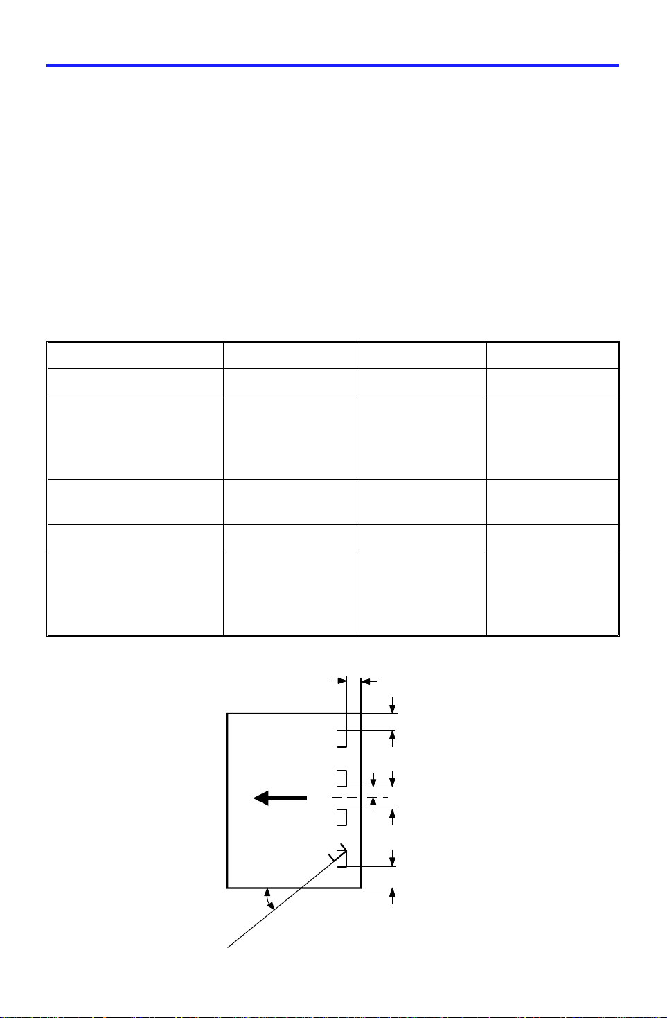
Staple Position:
157 g/m2, 42 lb 157 g/m2, 42 lb 80 g/m2, 20 lb
50 sheets/bin
2 sided copies:
40 sheets/bin
Sideways:
A4, 81/2" x 11"
Lengthwi s e :
A5, 51/2" x 81/2"
all sizes:
40 sheets/bin
2 sided copies:
35 sheets/bin
a
d
e
a = 6 ± 3 mm
b = 6 ± 3 mm
c = 6 ± 3 mm
d = 66 ± 3 mm
e = 132 ± 2 mm
θ = 45 ± 5°
B5, 81/2" x 11"
all sizes:
50 sheets
θ
1
b
Page 3

SPECIFICATIONS 23 April 1993
Staple Replenishmen t: Cartridge exchange (5,00 0 pie ces/ cartridge)
Power Source: DC24V (from copier)
Power Consumption: Average: less than 80W
Maximum:
in sort/stack mode: less than 100W
in staple mode: less than 300W
Dimensions:
566 x 583 x 978 mm
(W x D x H)
Weight: Approximately 52 kg
2
Page 4
23 April 1993 COMPONENT LAYOUT
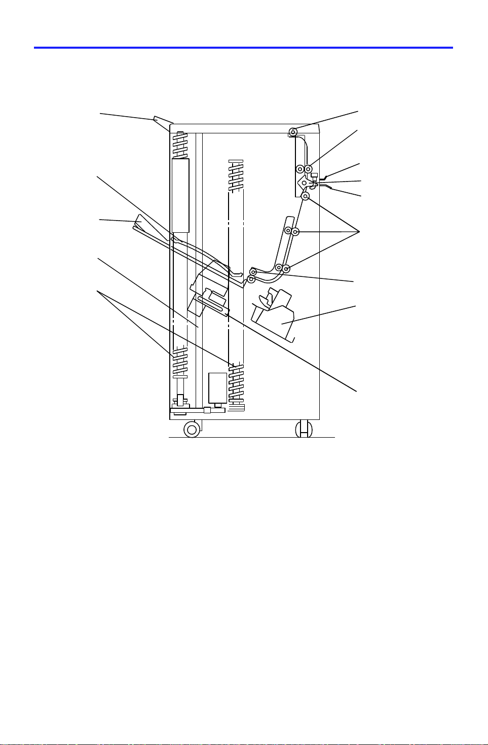
2. COMPONENT LAYOUT
2.1 MECHANICAL COMPONENT LAYOUT
14
13
12
11
1
2
3
4
5
6
7
8
9
10
1. Proof Tray
2. Proof Exit Rollers
3. Proof Transport Rollers
4. Upper Entrance Guide
5. Turn Gate
6. Lower Entrance Guide
7. Sorter Transport Rollers
8. Sorter Exit Rollers
9. Staple Unit
10. Grip Assembly
11. Helical Wheels
12. Jogger Plate
13. Bins
14. Upper Guide Plate
3
Page 5
4
13
13
COMPONENT LAYOUT 23 April 1993
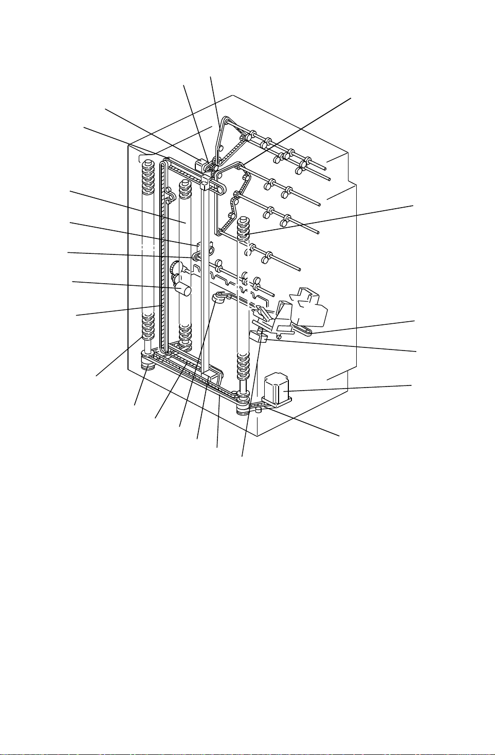
2.2 DRIVE LAYOUT
3
2
1
5
5
16
15
14
5
9
13
1. Main Motor
2. Main Drive Belt
3. Proof Drive Belt
4. Sorter Drive Belt
5. Helical Wheels
6. Staple Unit Drive Belt
12
11
6
7
8
9
9
10
9. Wheel Drive Belts
10. Grip Drive Belt
11. Jogger Motor
12. Staple Unit Drive Motor
13. Jogger Drive Belts
14. Bin Rear Plate Drive Motor
7. Gripper Motor
8. Bin Drive Motor
15. Sorter Exit Drive Belt
16. Sorter Exit Motor
4
Page 6

23 April 1993 ELECTRICAL COMPONENT DESCRIPTION
3. ELECTRICAL COMPONENT DESCRIPTION
Please refer to the electrical component layout on th e reverse side of the
Point to Point (Water Pro of Paper) fo r symbol an d ind ex number.
Symbol Name Function
Motors
M1 Ma in Drives the paper transport rollers. 1
M2 S ta ple Feeds the staples and drives the
stapler hammer.
M3 G rip Drives the grip assembly forward
and backward into the bin to grip
the copies and bring th em to the
stapling position.
M4 B in Drive Drives the bins upward and
downward by rotating the thre e
helical wheels.
M5 Jo gg er Drives the jogger plate to jog the
copies against the front side plate.
M6 S taple Unit Drive Drives the staple unit according
to the stapl e position an d angle.
M7 B in Rea r P lat e Drive Drives the bin rear plate down
and up.
Index
No.
10
16
18
20
23
24
M8 S ort er Exit Delivers the paper into the bins. 27
Sensors
S1 Bin Jam (LED) Detects if there is paper jams at
the distribution sect ion and
detects if there is paper in the
bins (light emitting element).
S2 Proof Exit Detects paper jams at the proof
tray exit.
S3 Entrance Detects paper jams at entrance
guides.
S4 Staple HP Detects if the staple hammer is in
the home position.
S5 Staple End Detects staple end. 9
S6 Paper Detects whether copies are under
the hammer.
5
3
4
5
8
11
Page 7

ELECTRICAL COMPONENT DESCRIPTION 23 April 1993
Symbol Name Function
S7 Staple Unit HP Detects if the staple unit is in the
home position.
S8 Grip HP Detects if the grip assembly is in
the home position.
S9 Bin Jam (Photo Tr.) Detects paper jams at the
distribution section and detects if
there is paper in the bins (light
receiving element).
S10 Wheel Sensor Detects the bin position. 19
S11 Bin HP Detect s if the bins are in the
home position.
S12 Jogger HP Detects if the jogger plate is in
the home position.
S13 Bin Rear Plate Open Detects if the bin rear p lat e is in
the open position .
S14 Bin Rear Plate HP. Detects if the bin rear plate is in
the home (closed) position.
Index
No.
13
15
17
21
22
25
26
Solenoids
SOL1 Turn Gate Opens and closes the turn gate to
direct the copies into eit he r the
proof tray or the bins.
SOL2 Grip Opens and closes the grip arms
to grip copies on the bins.
SOL3 Grip Arm Positioning Moves the grip ass’y to the rear
and front to catch or release the
paper to carry to the stapler.
PCBs
PCB1 DC Supply Provides DC power (In put: 24V
DC, Output:24V/5V DC)
PCB2 Main Control Controls all sorter stapler
functions.
Switches
SW1 Door Safety Cuts the DC power when the
front door is opened.
2
12
14
7
28
6
6
Page 8
[D]
23 April 1993 BASIC OPERATION
4. BASIC OPERATION
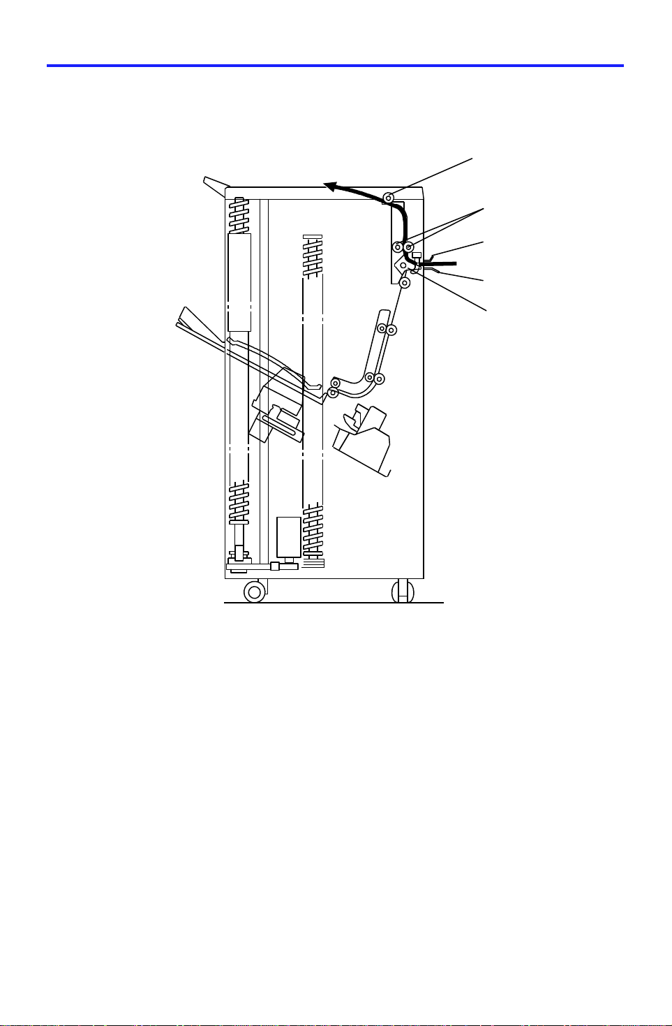
4.1 NORMAL (PROOF MODE) AND SORT/STACK MODE
[C]
[A]
[A]
[B]
Copies exiting the copier pass thro ug h the entrance guide plates [A] to the
turn gate section. The turn gate [B] will send copies eith er to the proof tray or
to the bins, depending on the mod e.
- Normal (proof) mode - (from the turn gate section to the proof tray)-
The turn gate solenoid energize s to tu rn th e turn ga te clo ckwise whe n the
Start key is pressed. The main moto r t urn s coun te rclockwise to rot at es th e
vertical transport rollers [C] and pro of exit roller [ D]. The turn gate directs
copies through the proof transpo rt sect ion to the proof tray.
7
Page 9
BASIC OPERATION 23 April 1993
- Sort mode - (from the turn gate section to the bins)
[F]
[E]
[D]
[A]
[B]
[H]
[C]
[I]
[G]
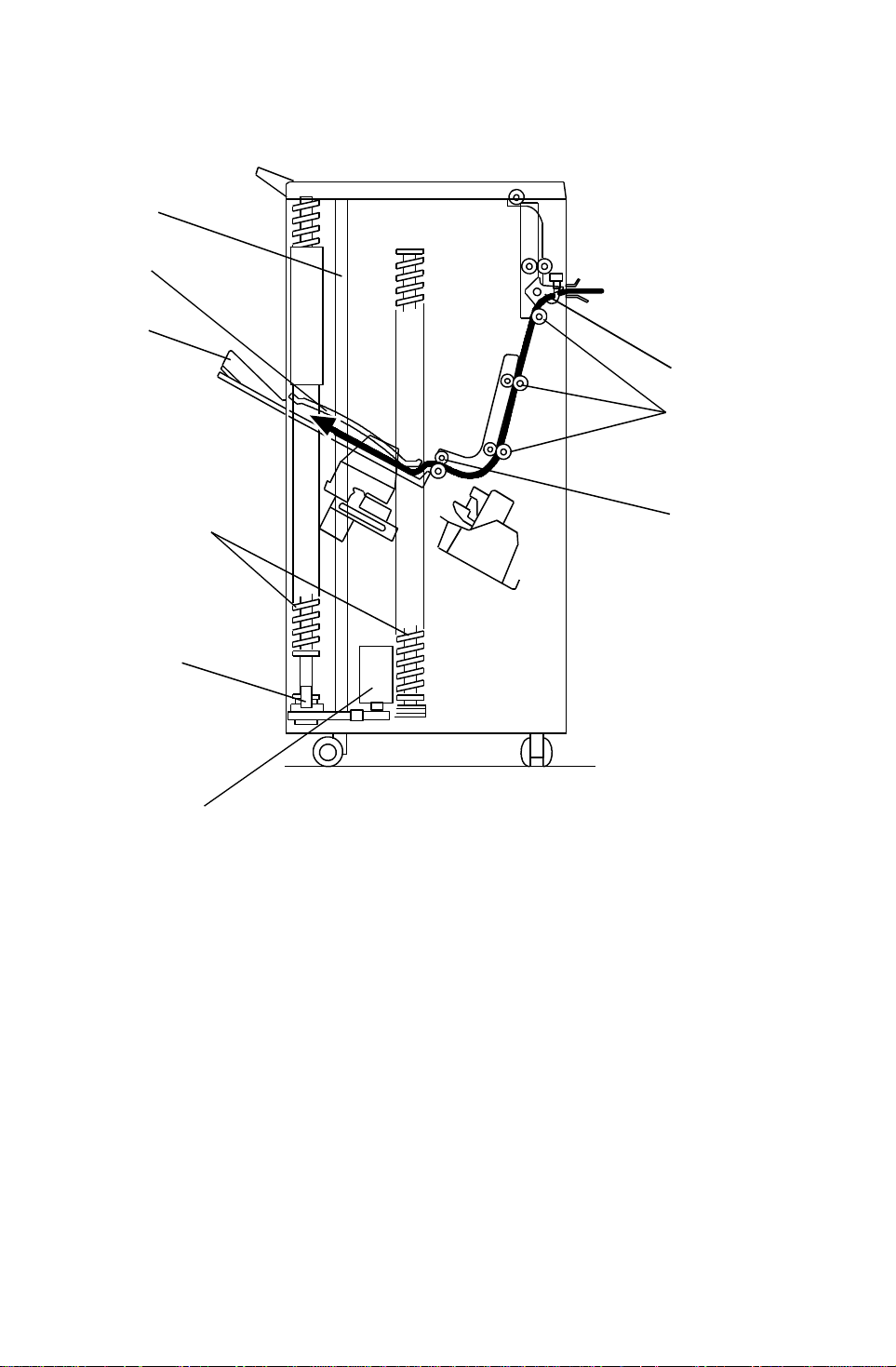
In this mode, the tu rn ga te solenoid stays off to keep the turn gate [A ] at the
upper position. The main motor turns clockwise to rotates the sorter transport
rollers [B] and the exit motor rotates the exit rollers [ C].
The turn gate directs copies to the sort er bin s thro ug h the sort er transport
section, then the first copy is delive red between the top bin [D] and the upper
guide plate [E] .
The jogger plate [F] the n jog s to squ are the copies each time.
Before the next copy reache s the sorte r exit roller, the bin drive motor [G]
rotates and advances the bin on e ste p (the he lical whe els [H] ro tate once ).
When the cut out of the actuator reaches below the wheel sensor [I], the bin
drive motor turns off.
Bins advances each time copies are de livere d.
8
Page 10

23 April 1993 BASIC OPERATION
- Stack mode - (from the turn gate section to the bins)
[F]
[E]
[D]
[A]
[B]
[H]
[C]
[I]
[G]
As with sort mode, the tu rn ga te solenoid stays off and th e turn gate [A] also
stays up when the start key is pressed. The ma in mot or tu rns clockwise to
rotate the sorter transport rolle rs [ B] and the exit mot or rot at es th e exit rollers
[C].
The turn gate directs copies to the sort er bin s thro ug h the sort er transport
section, then th e copies are delivered between the top bin [D] and the upper
guide plate [E] .
The jogger plate [F] the n jog s to squ are the copies each time.
All copies of the copy run are then fed to the first bin . Whe n th e fin al cop y is
delivered, the whe el drive motor [G] turns and advances the bin one step (the
helical wheels [H] rotat e on ce). When the cut ou t of the actuator reache s
below the wheel sensor [I] , the bin drive mot or tu rns of f.
9
Page 11
BASIC OPERATION 23 April 1993
4.2 STAPLE MODE
[Fig. 1]
[Fig. 2]
[Fig. 3]
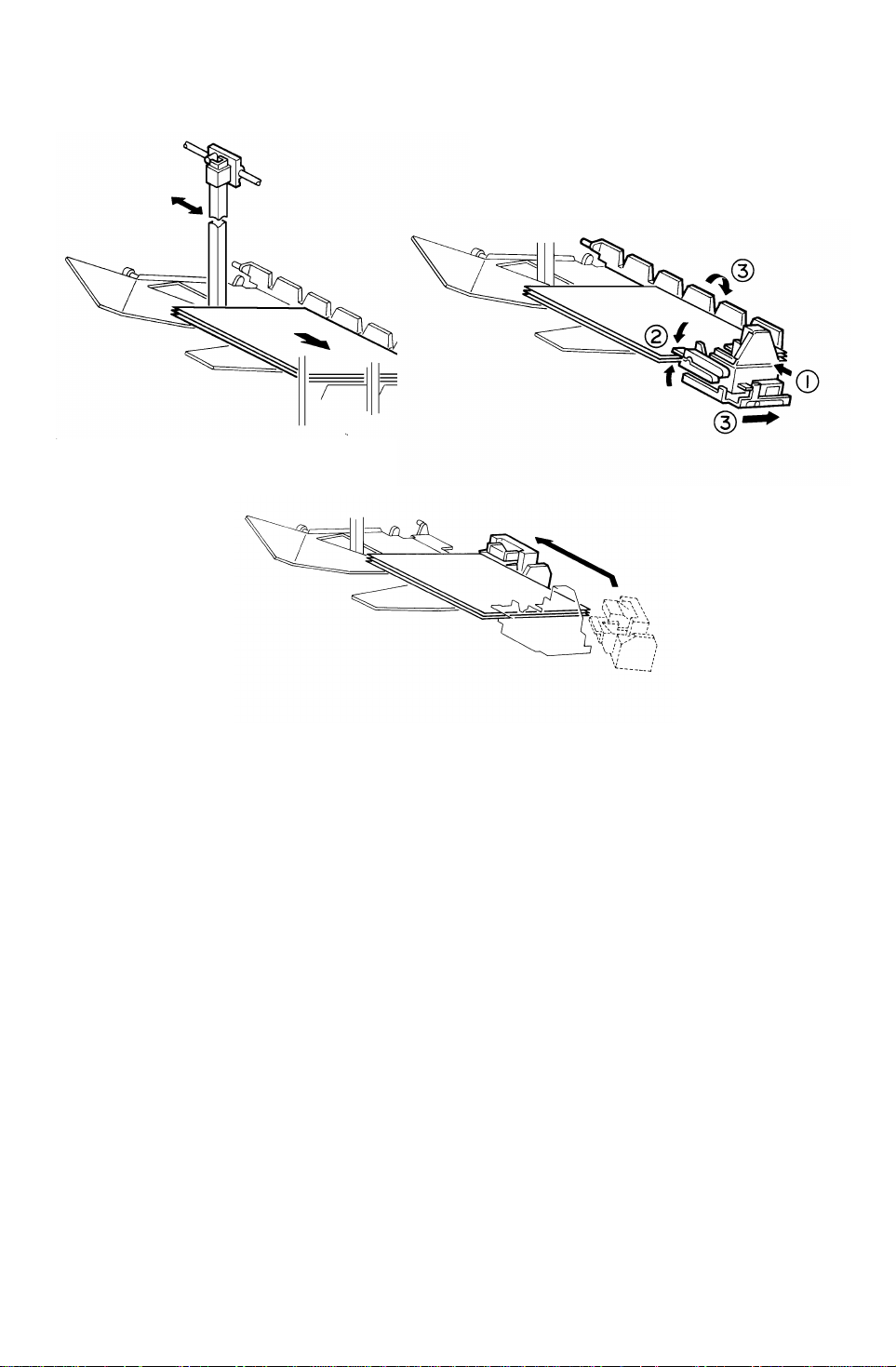
When the final set of copies is jogged [Fig. 1], the staple unit staples the
stacked copies as follows: The grip arms move inside the front sid e pla te and
catches the paper. The bin rear plate is turned so as to be flat wit h th e sorter
bin. The grip assembly brings the copies down underneath the stapler [Fig.
2]. The staple unit changes the position (the position varies depending on the
copy size and staple mode) and the stap ler sta ples the copies [Fig. 3].
10
Page 12
23 April 1993 BASIC OPERATION
[Fig. 4]
[Fig. 5]
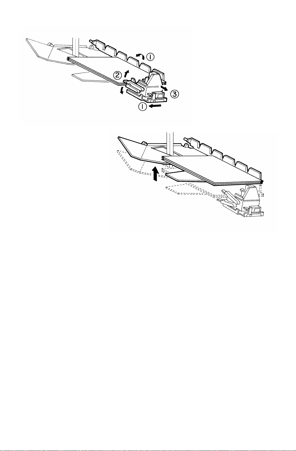
The grip assembly brings the stap led co pie s back to the bin and the bin rear
plate returns to the original position.
The grip assembly releases th e copies and return to outside the front side
plate so as not to disturb th e bin movement [Fig. 4].
The bin advances one step [Fig. 5].
When the final set of copie s is sta ple d, the staple unit is returned to the home
position.
There are two staple modes.
1) Automatic stapling:
In ADF mode, when the staple mode is select ed before pressin g the start
key, copies will be delivered to each bin and sta ple d auto mat ically.
2) Manual stapling:
In sort mode, after copies are sort ed in the bins, the copie s will be stap led
when the manual staple key is pressed then staple position is selected. In
stack mode, manual staplin g is imp ossib le.
11
Page 13
[B]
TURN GATE SECTION 23 April 1993
5. TURN GATE SECTION
[I]
[D]
[G]
[A]
[C]
[H]
[F]
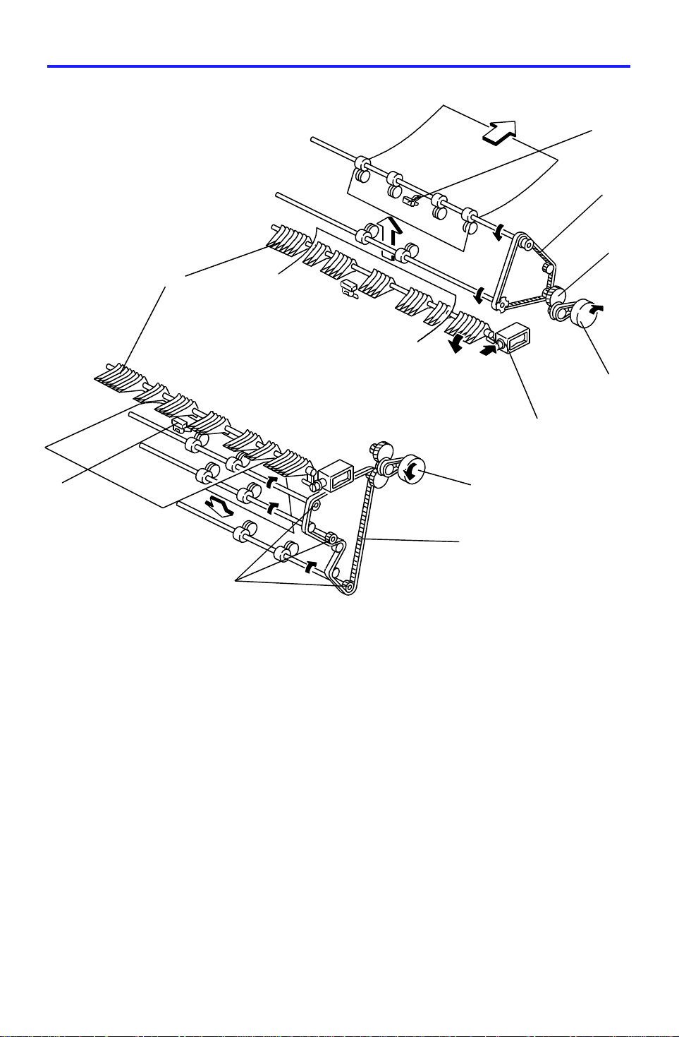
The turn gate [A] send s copies to the proof tray or the sort er bins depending
on the mode. In the proof mode, the turn gate solenoid [B] turns on and the
main motor [C] turns clockwise whe n th e sta rt key is p resse d.
The turn gate [A], directs copies upward through the proof transport section
to the proof tray. In this mode, the main motor drive is transmitt ed by both the
proof drive belt [D] and sorter drive belt [E] . Howe ver the one way clutch in
each sorter transport rolle r drive gear [F] does not transmit th e drive to the
sorter transport rollers.
In the sort, stack and stap le modes, the turn gate soleno id sta ys o ff to dire ct
copies downward to the sort er transport section. When the start key is
pressed, the main motor [C] turns counte rclockwise .
In this mode, the main motor drive is not transmitted to the pro of drive belt [D]
because of the one way clut ch in the pulley [G].
[C]
[E]
The entrance [H] and the proof exit [I ] sensors monitor the paper jam.
12
Page 14
23 April 1993 BIN DRIVE MECHANISM
6. BIN DRIVE MECHANISM
[B]
[E]
[D]
[G]
[A]
[C]
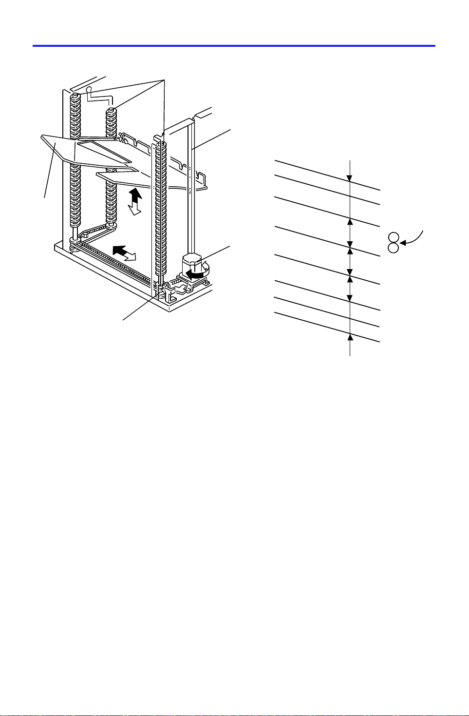
The bin drive mechanism moves th e bin s up an d do wn to receive copies. The
main components in this mecha nism are the bin drive moto r [A] , the three
helical wheels [B], the wheel sensor [C], and the bin s [D] themselves. There
are four pins on each bin. Three of them fit in th e slot on the helical whe els.
Another pin fits into th e slot [E] of the front side fra me.
The pins slide up and down in these slots.
Three timing belts transmit the drive from the bin drive mot or to the three
helical wheels. When it rotates clockwise, the bin s lift (black arrow) and when
it rotates counterclockwise, the bins lower (whit e arro w). The re is a wheel
sensor actuator on the fron t he lical whe el, the actu at or has a slo t which
detects when the helical wheel has rotated 360 degrees.
[F]
15
30
45
40
40
15
15
When the bins are advanced, the helical wheels rotate once (360 degrees )
for each step.
As the pitch of the spiral on the helical wheel is greater when bins are at the
staple and paper exit area than when bins are elsewhere, the amount of bin
shift is greater when bin s are at the staple and paper exit are a. This le ave s
enough space to staple [F] and stack paper [G] and reduces the total
machine height.
13
Page 15
[E]
BIN HOME POSITION 23 April 1993
7. BIN HOME POSITION
[A]
[B]
[D]
[C]
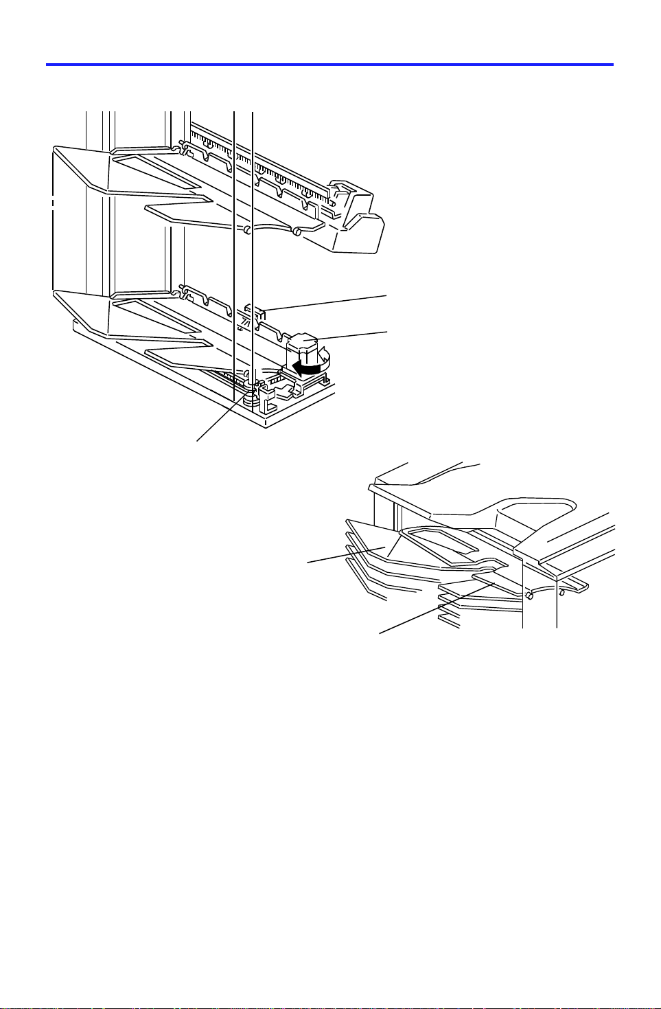
The bin home position sensor [A] and the wheel sensor [B] ensure that the
sorter exit roller is between the upper gu ide plat e [C] and the 1st bin [D] whe n
all the bins are in the home position.
When the main switch is turned on, the bin lift mot or [E] lowers the bins (turns
counterclockwise) until the bottom bin actua tes the bin home positio n sen sor.
Then, the bin lift motor raises the bins (turns clockwise) until the wheel
sensor activates. Thu s, the bins are in the home positio n.
14
Page 16
300 msec.
23 April 1993 JOGGER SECTION
8. JOGGER SECTION
[B]
[A]
Copier Main
Motor
Jam Sensor
Jogger Motor
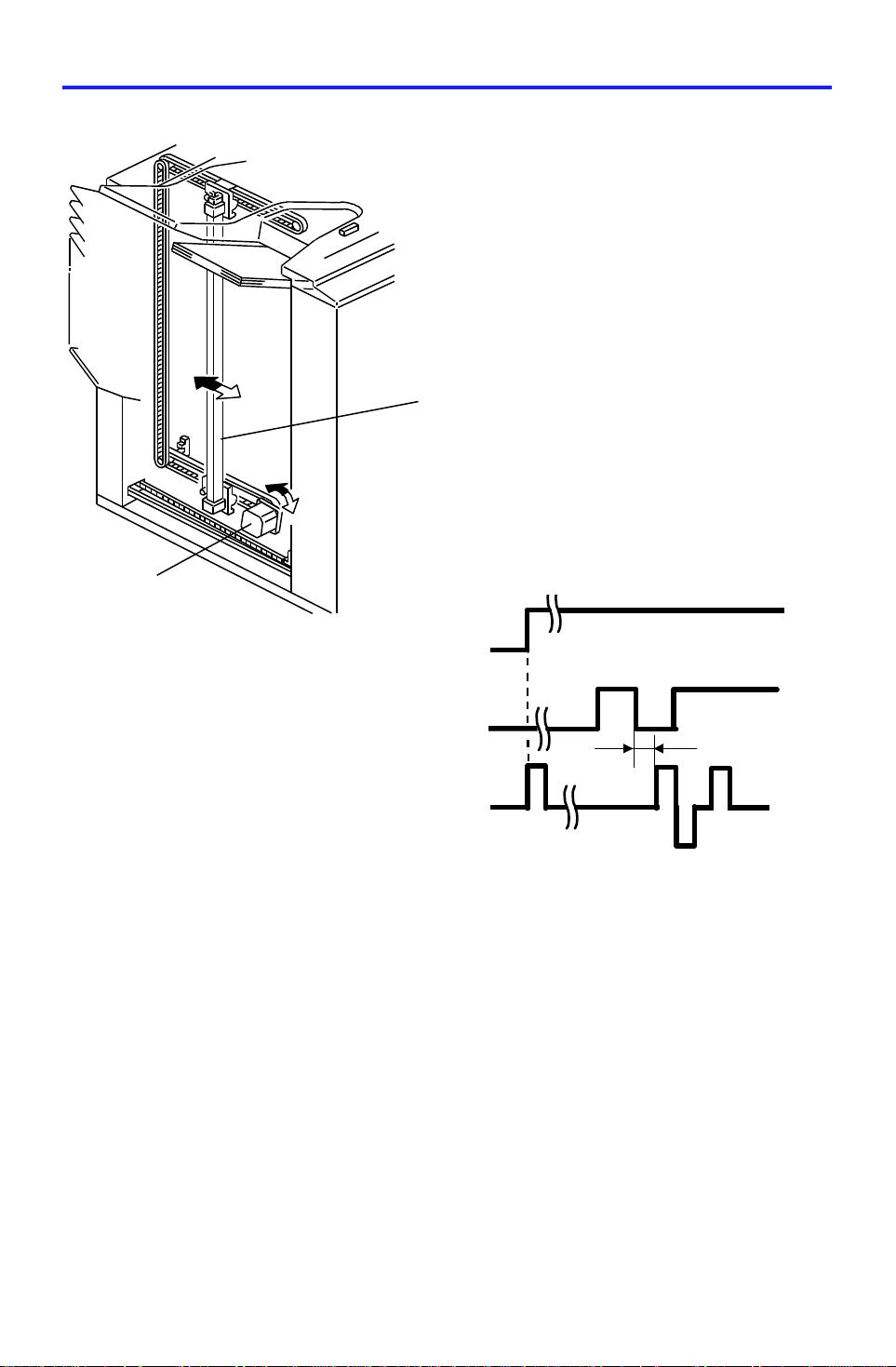
When the Start key is pressed in the sort , sta ple and stack modes, the copier
sends the paper size informatio n to the sorte r stap ler. In acco rdance with this
data, the jogger motor [A] drives the jogger plate [B] from the jogge r home
position to where the widt h is 10 mm wider th an the selected paper.
300 ms after the trailing ed ge of th e copy passes underneath the jam sensor,
the jogger motor rotates forward and in reverse. This makes the jogger plate
push all the copies against the front side plate to square th e she ets. When
the jogger plate pushes the pape r, th e pla te shift s to a positio n 5 mm wider
than the paper size when the bins lift. It shifts to a position 1 mm narrower
than the paper size when the bins lowers.
ON
The jogger plate ret urn s to 10 mm away f rom th e selected paper size for the
next copy.
When the bin sensor detects that all copies are removed from the bins after
jogging is finished, the jogg er pla te returns to its home posit ion.
15
Page 17
[C]
[C]
JOGGER SECTION 23 April 1993
[B]
Fig. 1
[D]
[E]
[A]
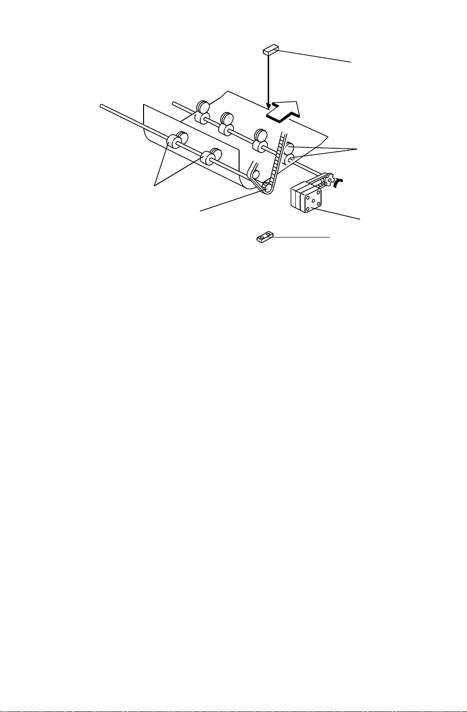
Normally all rollers in the sorter stapler transp ort the paper at a speed of
360mm/sec.
To have enough paper jogging time, the sorte r exit motor [A] rotation speed
changes to transport the pap er quickly a nd to sta ck the paper smoothly into
the bins as follows:
360mm/sec: When the sorter exit ro ller [B ] cat ches the leading edge of the
paper
1,000mm/sec: After the jam senso rs [ C] dete cts th e lea din g edge of the pape r
600mm/sec: When releasin g the trailing edge of the pap er
The transport roller [D] is driven at a speed of 360mm/sec const an tly,
however, when the sorter exit roller [B] rotates quickly, the transport rollers
also rotate quickly with the pulled paper becau se of the one way clutch in the
drive gear [E].
- Jogger Off Conditions -
1. Under the following conditions, the jogger plate does not jog after copies
are delivered to the bins.
• If paper is loaded in a bin by hand while the sort/stack or staple mode
is selected.
• If the selected paper size does not match stapling specifications.
• If copy of smaller width is delivered in the bins lat er in th e "Mixed
sizes" mode.
2. If paper is in a bin before the main switch is turned on, the sort/stack
mode is disabled when th e sort key is to uch ed .
16
Page 18
[D]
[G]
23 April 1993 BIN REAR PLATE DRIVE SECTION
9. BIN REAR PLATE DRIVE SECTION
[I]
[A]
[G]
[F]
[J]
[E]
[A]
[F]
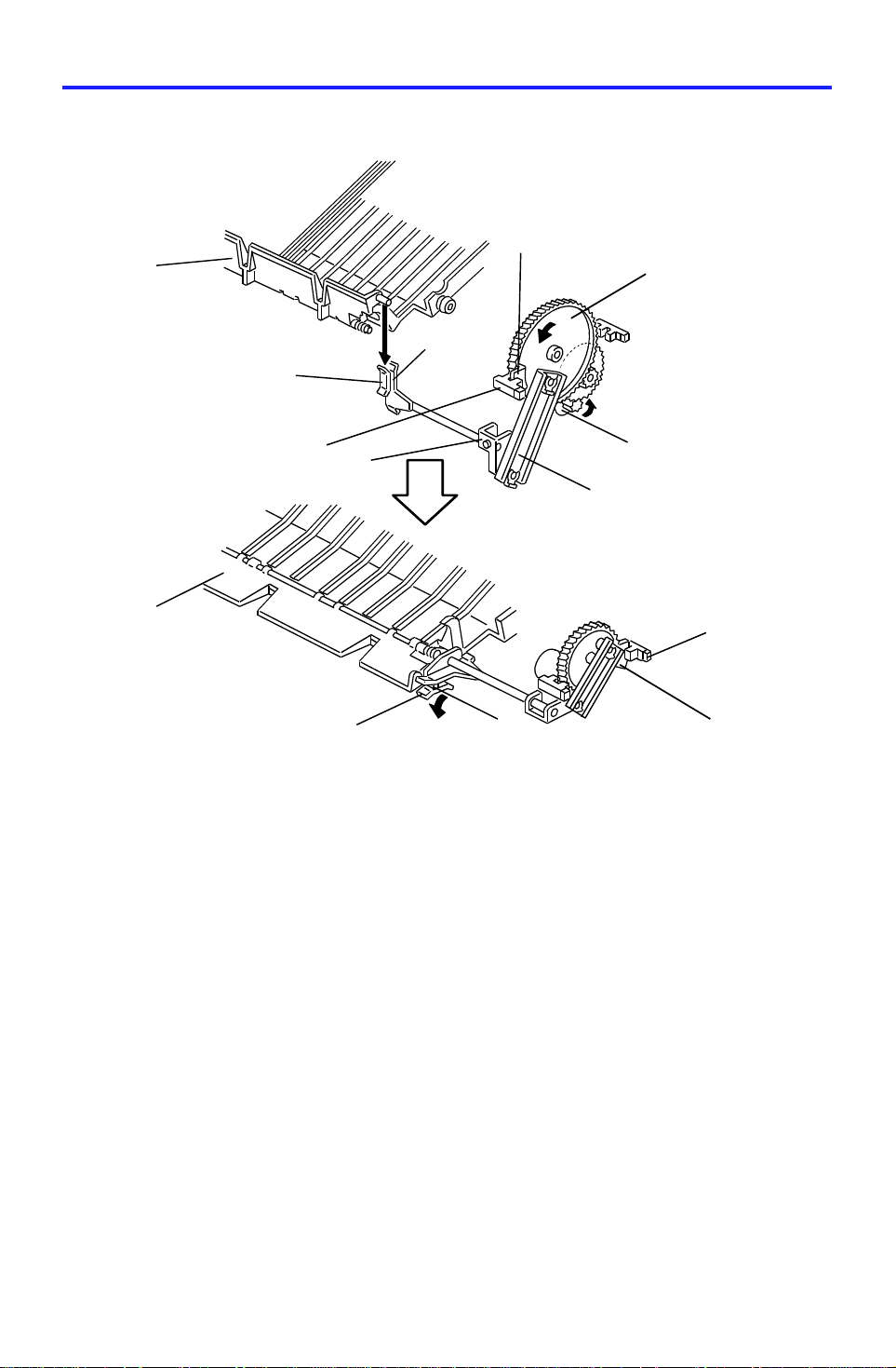
The bin rear plates [A] basically st and up as shown in Fig.1 . The y are
lowered only during stapling as sho wn (Fig.2).
In the staple mode when all copies have been jogged by the jogger plate, the
bin rear plate drive motor [ B] rota tes gear [C]. Gear [C] drives the pisto n rod
[D] to push the lever [E] do wn.
The holder [F] engaging the pin [G] on the bin rear pla te lowers in
accordance with the lever [E] position. Thus, the bin rear plate be come s flat
so as not to interfere with the copies be ing brou gh t to the st aple po sitio n by
the grip assembly.
During stapling, th e bin rear plate open sensor [H] is interru pted by the
actuator [I] (Fig.2).
[C]
[B]
[H]
[I]
When the bin rear plates are in the home position, the bin rear plate HP
sensor [J] is interrupted by th e actua to r [I] (Fig. 1).
Under this condition , a pin [G] enters the holder [F] or pa sses th rough it.
After stapling is comple ted and stapled paper is returned to the bin, gear [C]
rotates 180 degree s and the bin rea r p lat e returns to its home position.
17
Page 19
GRIP ASSEMBLY 23 April 1993
10. GRIP ASSEMBLY
[C]
[B]
[A]
Staple Unit
Drive Motor
Grip Arm Positioning
Solenoid
Grip solenoid
Bin Rear Plate
Drive Motor
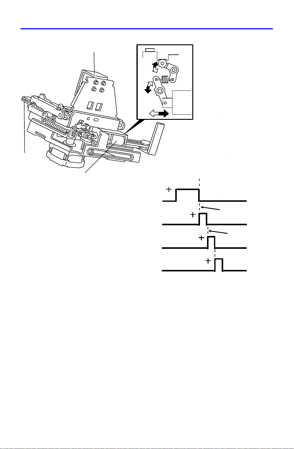
The grip assembly works as follows:
❶ When the staple unit re ach es the staple position, th e grip arm positioning
solenoid [A] activates and the plunger is pulled in to move the grip arms
[B] to the rear side of the machine. This is to access the paper on th e bin .
The grip arm positioning solenoid has a strong magnet inside , the plunger
keeps this condition until t he solenoid is energized by an opposite charg e.
The right upper part of the illustration (squa red part ) shows the
mechanical linkage as seen from the top.
❷ The grip solenoid [C] activates to close the grip arms and th e grip arms
catch the papers.
As for the grip arm position ing solenoid, the plung er keeps the grip arms
closed until the solenoid is energized by an opposite charge.
❶
OFF
OFF
❷
OFF
OFF
18
Page 20
[C]
23 April 1993 GRIP ASSEMBLY
[B]
[E]
[A]
[F]
[D]
Bin Rear Plate
Drive Motor
OFF
❸
Grip Motor
OFF
❹
Staple Motor
OFF
❺
Grip Solenoid
OFF
❻
Grip Arm Positioning
OFF
Solenoid
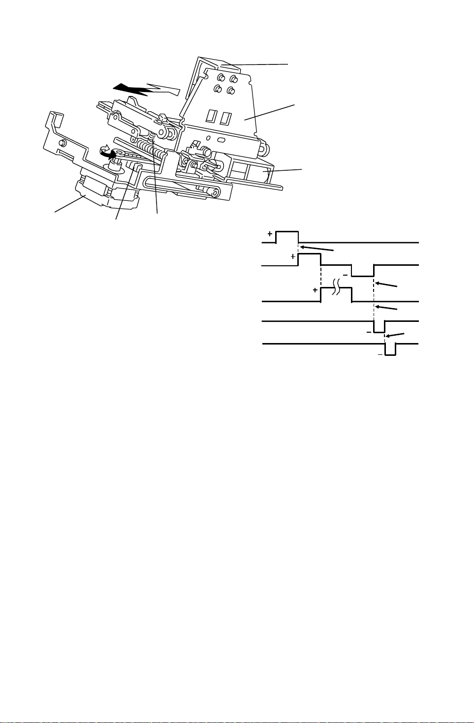
❸ After the bin rear plate drive moto r lowers th e bin rear plate, the grip motor
[A] turns clockwise (white arrow) until the gripp er [B ] carrie s the paper to
the staple position.
❹ After stapling is finished, the grip mot or tu rns counterclockwise to move
the stapled copies caught by the grip arms back to th e bin .
❺ When the grip solenoid [C] act ivates in the opposite way (as when it
activates to catch the paper), the return spring s [D] op ens the grip arms
to release the papers which remain s in the bin.
❻ The grip arm positioning solenoid [E ] act ivates to return the grip arms to
the home position to prepare for the next staple cycle.
The grip home position senso r [ F] is actuated while the grippe r is in the ho me
(grip) position.
The sorter stapler main control board sends the ap pro priate pulses to the grip
motor (stepping motor) [A] to determin e the grip posit ion and staple position.
Vertical staple position s are ad just ab le by cha ng ing the numb er of the
stepping motor pulses from t he home posit ion ( 1 SP Adjust men t - PAG E1 1).
19
Page 21
STAPLE UNIT 23 April 1993
11. STAPLE UNIT
11.1 STAPLE UNIT DRIVE MECHANISM
[B]
[A]
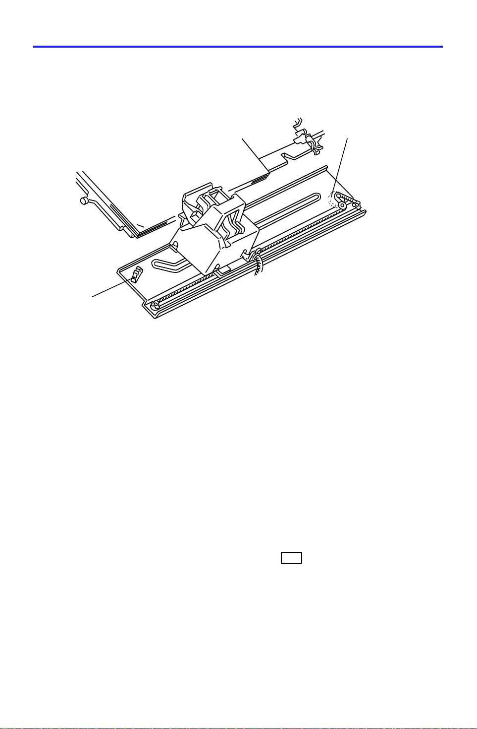
The staple unit moves from the home position (top slant position) to the rear
side of the machine in ord er to ch ange the stap le po sition. The staple HP
sensor [A] activates when the st aple un it is in the home posit ion. In Top Slant
mode, the staple r is on ly at th e home position. In "Top" (" Bo ttom") single
staple mode, the staple unit move s to th e fro nt (re ar) sing le sta ple position
and stays there until all stapling is completed. It then returns to the ho me
position. In "2 Staples" mode or "Bottom" single staple mode, the staple
positions differ accordin g to the paper size. The staple unit drive mot or [B] is
a stepping motor, and the stap le po sitio n is decid ed by the numb er of step s
from the home position.
During stapling in the "2 St ap les" mo de , th e staple unit goes back and forth to
staple the two positions.
Horizontal staple positions are adju stable by changing the number of
stepping motor pulses from t he home posit ion ( SP Adjust men t PAGE11).
1
20
Page 22
23 April 1993 STAPLE UNIT
11.2 STAPLER
[C]
[G]
[B]
[F]
[E]
[A]
[D]
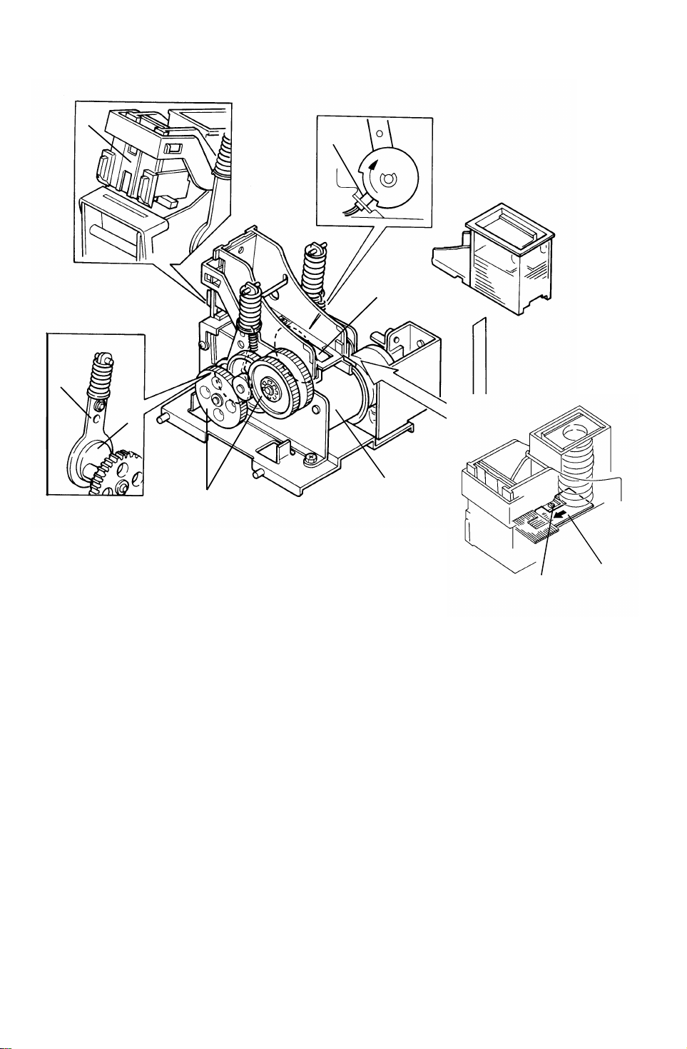
The stapler motor [A] drives the sta ple sheet drive belt [B].
[H]
[I]
The staple sheets are fed under th e hammer [C] .
The stapler motor drives th e sta ple hammer via gears [D], two eccentric ca ms
[E], and two links [F].
When the aligned copies are brought to the staple position by the grip, the
stapler motor starts rotating. When the cams complete one rotation, th e
staple home position sensor [G] is d e-a ctu at ed . The stap ler mot o r then stop s.
When the paper sensor in the grip assembly does not detect that the copies
are under the hammer, th e sta pler motor does not rotate.
A paper sheet [H] with a notch cut-in is positioned at the bottom of the staple
cartridge. This paper sheet is fed out aft er th e last stap le she et . Whe n th e
leading edge of the not ch in the sheet is detecte d by the staple end senso r
[I], the sorter sta ple r unit recognizes the staple ne ar en d con dition. After the
job is completed, the Add Sta ple indicator lights on the cop ier operation panel
and the Start key turns to re d whe ne ver the staple mode is selected.
21
Page 23

STAPLE UNIT 23 April 1993
- Staple Prohibit Conditions -
1. Under the following conditions, the staple mode is disabled when the
staple key on the operation panel is pressed.
If paper is in a bin before the main switch is turned on.
If the selected paper size does not match stapling specification s.
If the paper is fed from the by-pass feed table.
2. Under the following conditions, the staple mode is canceled.
If paper is loaded in a bin by hand while the staple mode is selected.
If only one sheet is delivered to th e bin.
If the stack, slip sheet or interrup t mod es are selected.
3. Under the following conditions, the manu al sta pling mode in sort mode is
prohibited.
If paper is loaded in a bin by hand while the sort mod e is selected.
If the paper size in the bin does not match sta plin g spe cifica tions.
If only one sheet is delivered to th e bin.
If smaller width paper is delivered on the bin later in "Mixed Sizes" mode.
If copies already stapled are left in the bin.
22
Page 24
23 April 1993 JAM DETECTION
12. JAM DETECTION
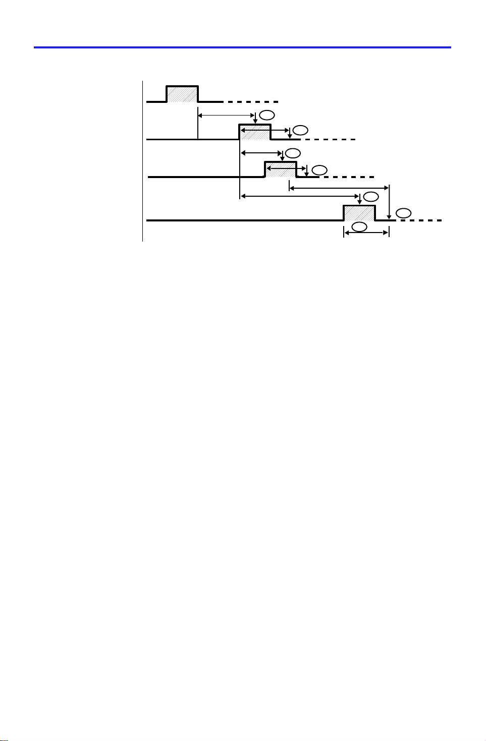
Copier Exit Sensor
J1
(1,250m sec)
J2
Entrance Sensor
Proof Exit
Sensor
Jam Sensor
- Sorter Jams -
300pls
*This is the jam checking timing for the 1st bin. Timing
depends on the bins.
280 pls
ON Check
J3
280pls
J4
436pls*
600pls*
1 pulse ≈ 3.61 ms
J5
J6
J7
280pls
The sorter stapler main control board detects jams when the following
conditions are detect ed . In these cases, a jam signal is sent to th e copier, the
copier stops the paper feed and indicates a sorter misfeed.
- Normal (Proof) mode -
J1: The entrance sensor ha s not turned on for the 1,250 ms af te r t he copie r
exit sensor turns on.
J2: The entrance sensor sta ys on for t he app rop riat e nu mbe r of pu lses (fo r
example, 280 pulses for A4 sideways) or more.
J3: The proof exit senso r has no t turned on for 300 pulses afte r t he ent rance
sensor turns on.
J4: The proof exit senso r st ays on fo r th e ap pro priate number of pulses (f or
example, 280 pulses for A4 sideways) or more.
- In Sort/stack or Staple Mode -
J1 and J2: Same as the Normal mode.
J5: The jam sensor has not tu rned on for 600 pulses after the ent rance
sensor turns on.
J6: The jam sensor stays on for the appropriate numb er of pulses (for
example, 280 pulses for A4 sideways) or more.
J7: The jam sensor turns on while the bin drive moto r t urn s on.
23
Page 25
TIMING CHART 23 April 1993
13. TIMING CHART
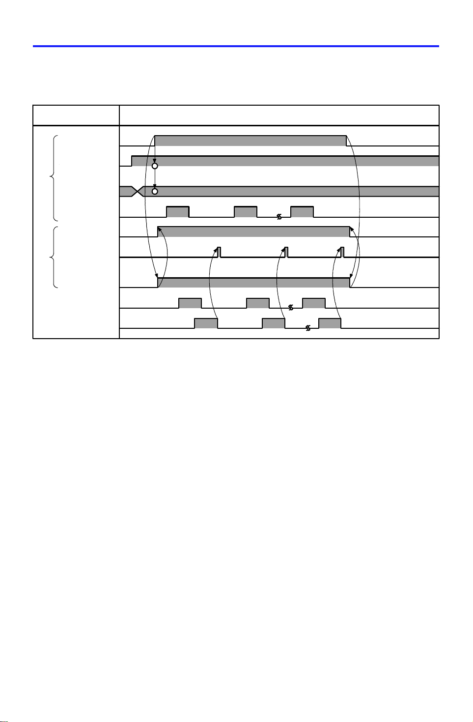
13.1 A377 SORTER/STAPLER TI MI NG CHART (PROOF MODE)
Timing ChartSignal
Motor ON
Proof mode
Paper size
dada
Exit signal
Sorter busy
S/S exit
signal
S/S main
motor ON
Entrance Sensor
Proof exit Sensor
24
Page 26
23 April 1993 TIMING CHART
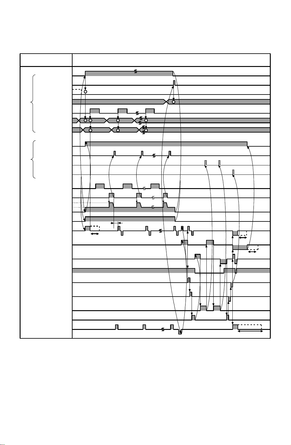
13.2 A377 SORTER/STAPLER TI MI NG CHART
(STAPLE MODE)
Signal
Motor ON
Staple ON
Proof mode
Staple mode
Exit signal
Paper size data
Bin data
Sorter busy
S/S Exit signal
Proof count
Job complete
Entrance sensor
Jam sensor
Sorter exit motor
Sorter main motor
Jogger motor
Staple unit
drive motor
Grip motor
NOTE 1
Timing Chart
300 ms
NOTE 1
NOTE 2
Grip HP sensor
Grip positioning
solenoid
Grip solenoid
Staple motor
Bin rear plate
drive motor
Bin drive motor
NOTE: 1. Jogger motor on time differs depending on the paper size.
2. Staple unit drive motor on time diffe rs dep en din g on the paper size.
3. Bin drive motor on time differs depend ing on the numbe r o f cop y
sets.
25
NOTE 3
Page 27

INSTALLATION 23 April 1993
14. INSTALLATION
14.1 ACCESSORY CHECK
Check the content s of the box according to the fo llowin g list.
Description Q’ty
1. Installation Procedure.............................................................1
2. Front Connecting Bracket.......................................................1
3. Rear Connecting Bracket........ .......... .. .......... .......... .. .......... .. .1
4. Staple Cartridge......................................................................1
5. Cushion...................................................................................1
6. Entrance Guide Mylar.............................................................1
7. Proof Tray...............................................................................1
8. Caster Stopper ....................................................................... 2
9. Philips Pan Head Screw - M4x12...........................................4
10.Philips Screw With Flat Washer - M4x6......... .. .. .. .. .. .. .... .. .. .. .. .1
11.New Equipment Condit ion Report (N.E.C.R.).................. .. .. ...1
(-17, -27 machines only)
12.Envelope for N.E.C.R..............................................................1
(-17 machine only)
26
Page 28
23 April 1993 INSTALLATION
14.2 INSTALLATION PROCEDURE
[B]
[A]
[B]
[A]
[B]
[A]
[B]
[A]
[A]
[E]
[C]
[D]
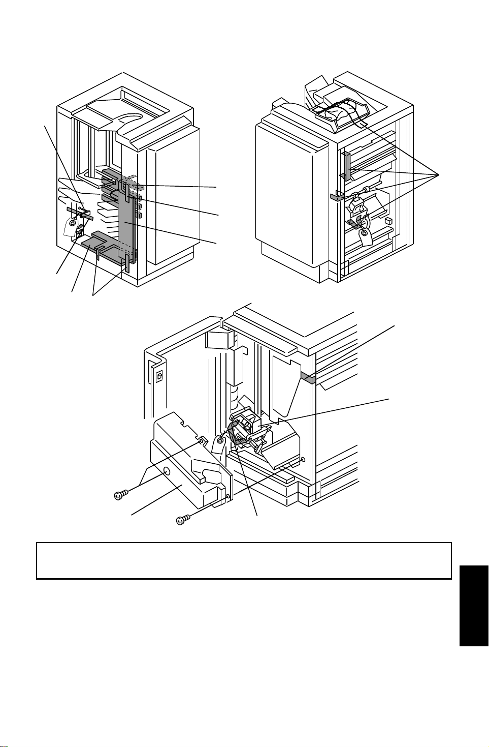
CAUTION: Unplug the copier power cord before starti ng the follow ing
procedure.
1. Remove the strips of tape [A] and th e cush ions [B].
2. Open the front door and remove the inner cover [C] (3 screws).
3. Remove the strip of tape [D] securing th e gripper unit and remove the
cushion [E]. Then re-inst all the inner cover [C].
27
(A377)
Sorter Stapler
Page 29
[C]
INSTALLATION 23 April 1993
[A]
[A]
[D]
[B]
[E]
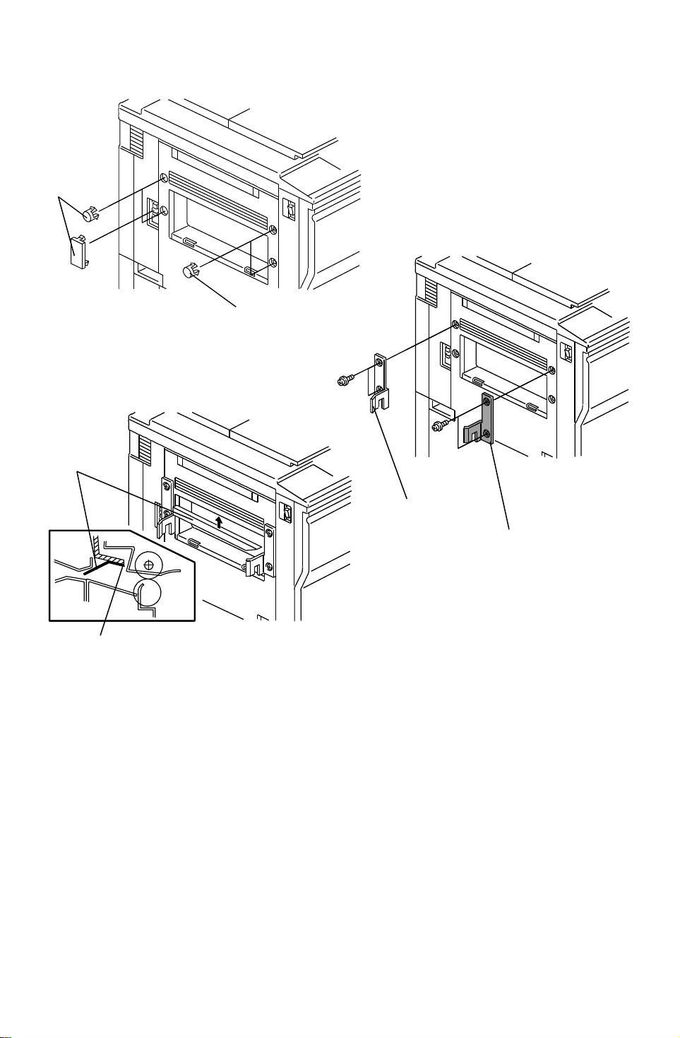
4. Remove five plastic caps [A] on the copier’s left cover.
5. Install the front connecting bracket [B ] (2 screws - M4 x 12) and the rear
connecting bracket [C] (2 screws - M4 x 12) on the copier.
6. Stick the entrance guide mylar [D] on the copier exit area as shown .
NOTE: Align the edge [E] of the cove r and the mylar.
28
Page 30
[D]
[A]
23 April 1993 INSTALLATION
[C]
[B]
[H]
[G]
[F]
[E]
[F]
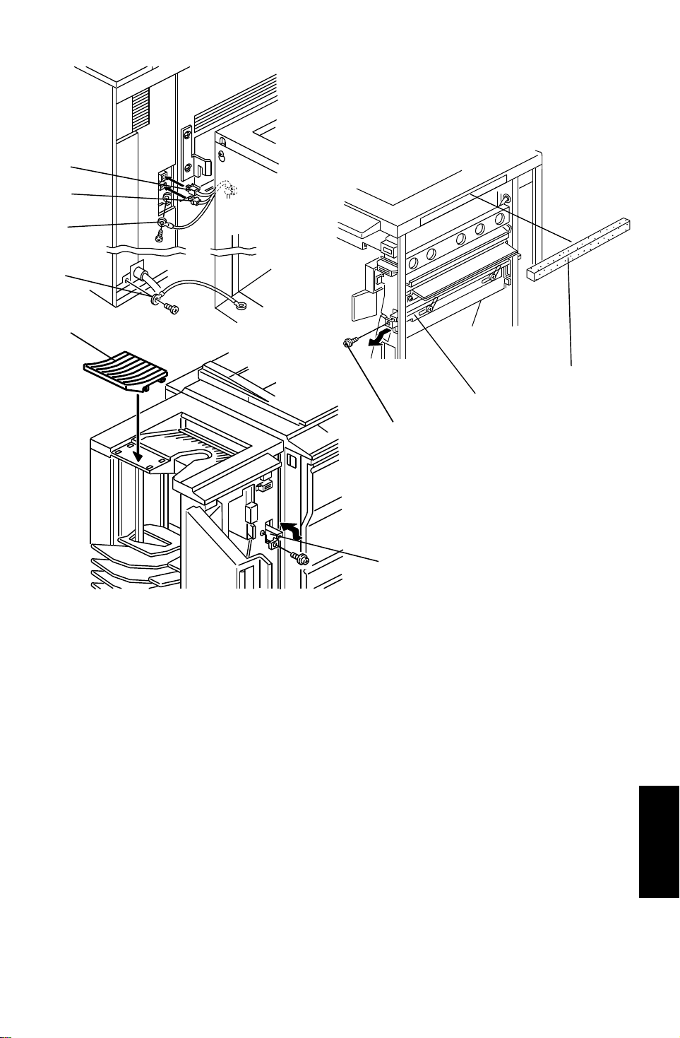
7. Secure the protective eart h wire [A ]* (1 screw with spring washer) and th e
wire [B] (1 screw with spring washer).
NOTE*:For all models other than those intended for Nort h Ame rica, the
green wire is intended as a functional ea rth and shou ld be
connected as shown.
8. Connect the 4P connector [C] and the fiber optic connector [ D].
9. Open the front door of the sort er sta pler and remove the screw [E] fixing
the locking lever [F], then lower the locking lever.
10. Stick the cushion [G] on th e proof tray.
11. Align and press the sorter stapler against the copier and fix them by
raising the locking lever [F].
12. Secure the locking leve r (1 screw).
13. Install the proof tray [H] .
29
(A377)
Sorter Stapler
Page 31
INSTALLATION 23 April 1993
[A]
[A]
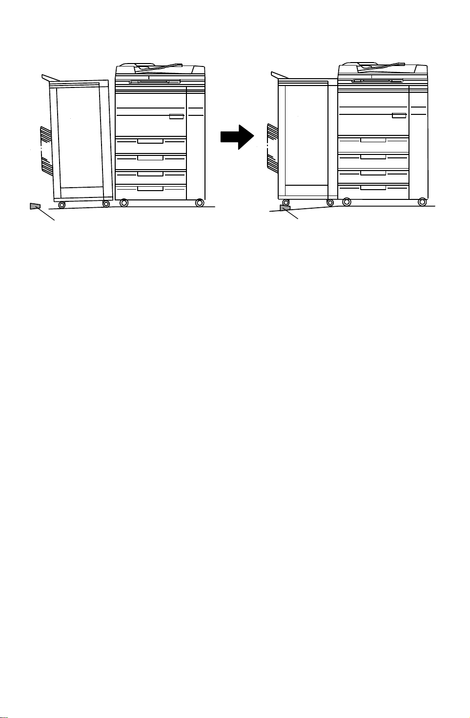
14. If the gap between the top of th e sorter stapler and the copie r is too great,
adjust by placing caster stop pe rs [A] .
30
Page 32
23 April 1993 INSTALLATION
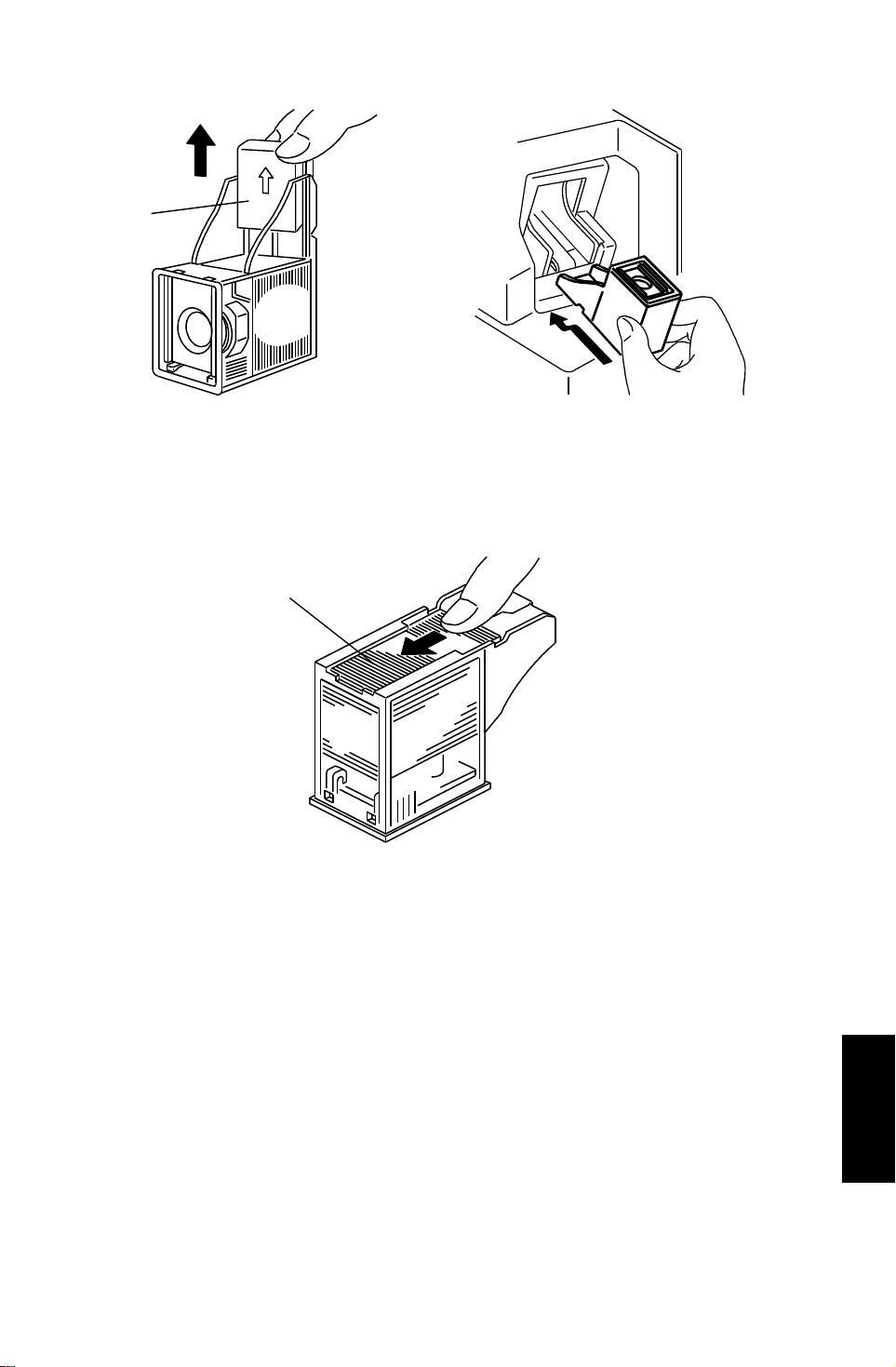
[A]
15. Remove the green plastic clip [A ] fro m t he st aple cartridge, and install the
cartridge in the stapler.
NOTE: When installing the staple cartridge, make sure that all the stap le
sheets [B] are in the init ial po sitio n.
[B]
16. Plug in the copier.
17. Turn on the main switch of the copier and test the operation of the sorte r
stapler.
NOTE: The copier automatically recognizes that the sorter stapler has
been installed.
The stapler will not staple for the first 10 or so copies until the
first staple moves to the proper position from the cartridge.
(A377)
31
Sorter Stapler
Page 33
SERVICE TABLES (MAIN CONTROL BOARD) 23 April 1993
15. SERVICE TABL ES (MAI N CONTRO L
BOARD)
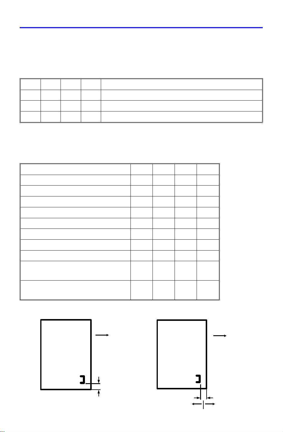
15.1 DIP SWITCHES
DIP SW100 0: OFF 1: ON
1 2 3 4 Function
0 0 0 0 Standard setting
1 0 0 0 Raises all bins to the top position.
0100Free run
DIP SW101 DIP SW102
Vertical Staple Horizontal Staple
Position Adjustment Position Adjustment
Adjustment Value 1 2 3 4
Standard Position 0 0 0 –
0.5 mm 1 0 0 0/1
1.0 mm 0 1 0 0/1
1.5 mm 1 1 0 0/1
2.0 mm 0 0 1 0/1
2.5 mm 1 0 1 0/1
3.0 mm 0 1 1 0/1
3.5 mm 1 1 1 0/1
- direction
–––0
(See the illustration below.)
+ direction
–––1
(See the illustration below.)
NOTE: The adjustment value and the combination of the dip switch positions
are exactly the same on DIP SW 101 and DIP SW 102 .
Feed
direction
Feed
direction
↑ + direction
↓ – direction
32
+ direction
– direction
Page 34

23 April 1993 SERVICE TABLES (MAIN CONTROL BOARD)
15.2 TEST POINTS
Number Function
TP100 GND
TP101 + 5 V
15.3 FUSES
FUSES Connected Point Rated Current and
Voltage
FUSE100 CN100-3 (+24 V) 250 V T5A
FUSE101 CN100-1 (+5 V) 250 V T2A
33
(A377)
Sorter Stapler
Page 35
REPLACEMENTS AND ADJUSTMENTS 23 April 1993
16. REPLACEM ENTS AND ADJUSTMENT S
16.1 EXTERIOR COVER REMOV AL
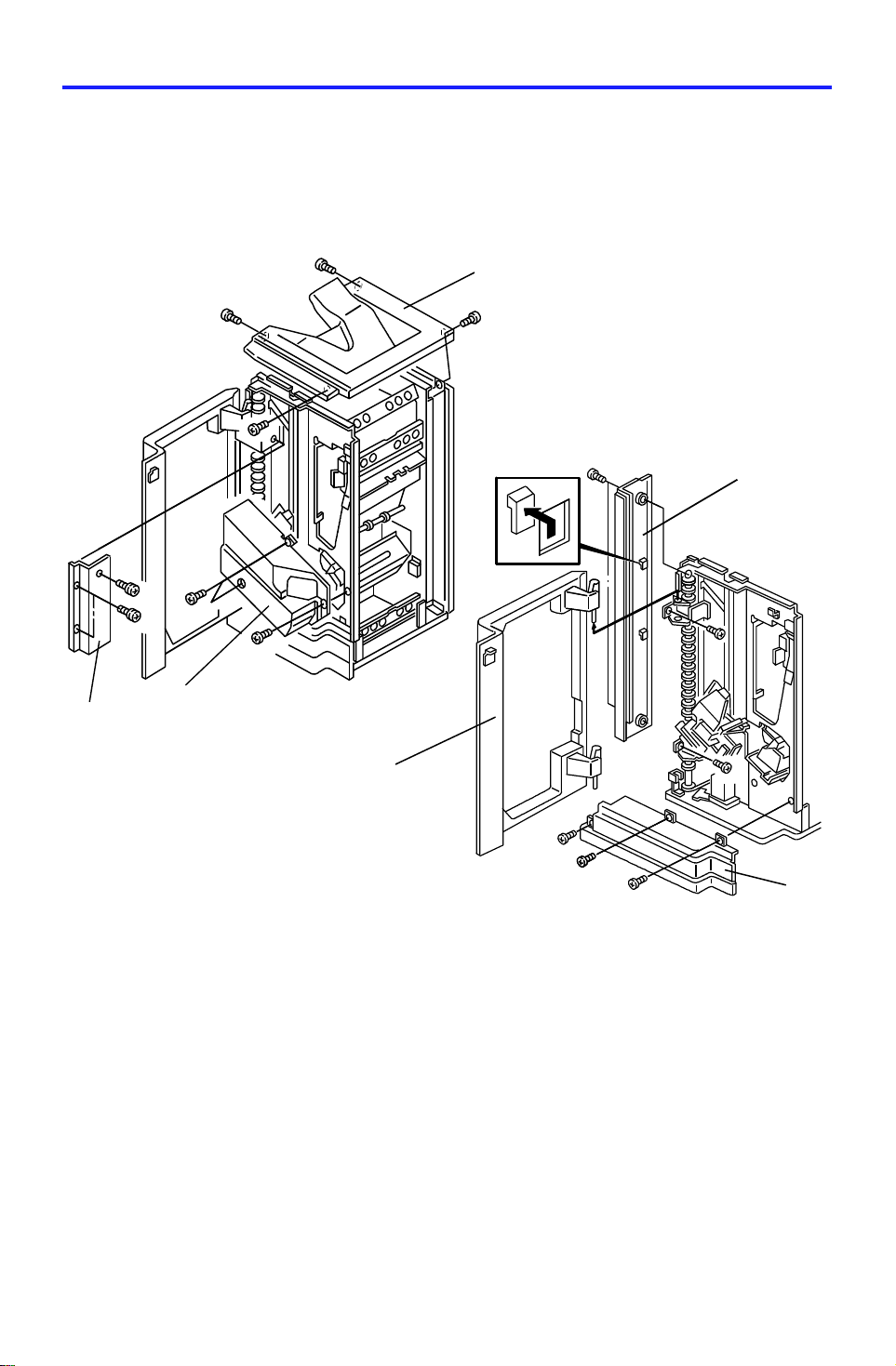
- Front side -
Remove the covers in the order as fo llows.
[A]
[D]
[B]
[C]
[F]
1. Remove the proof tray [A] (4 screws).
2. Open the front door .
3. Remove the front inner cover [B] (3 screws).
4. Remove the front wheel cover [C] (3 screws).
5. Remove the four screws fixing the front left cove r [D] an d remo ve the
front left cover by shifting the cover up to release the two hooks.
6. Remove the front lower cover [E] (3 screws).
7. Remove the front door [F] (2 hinge pin s).
[E]
34
Page 36
23 April 1993 REPLACEMENTS AND ADJUSTMENTS
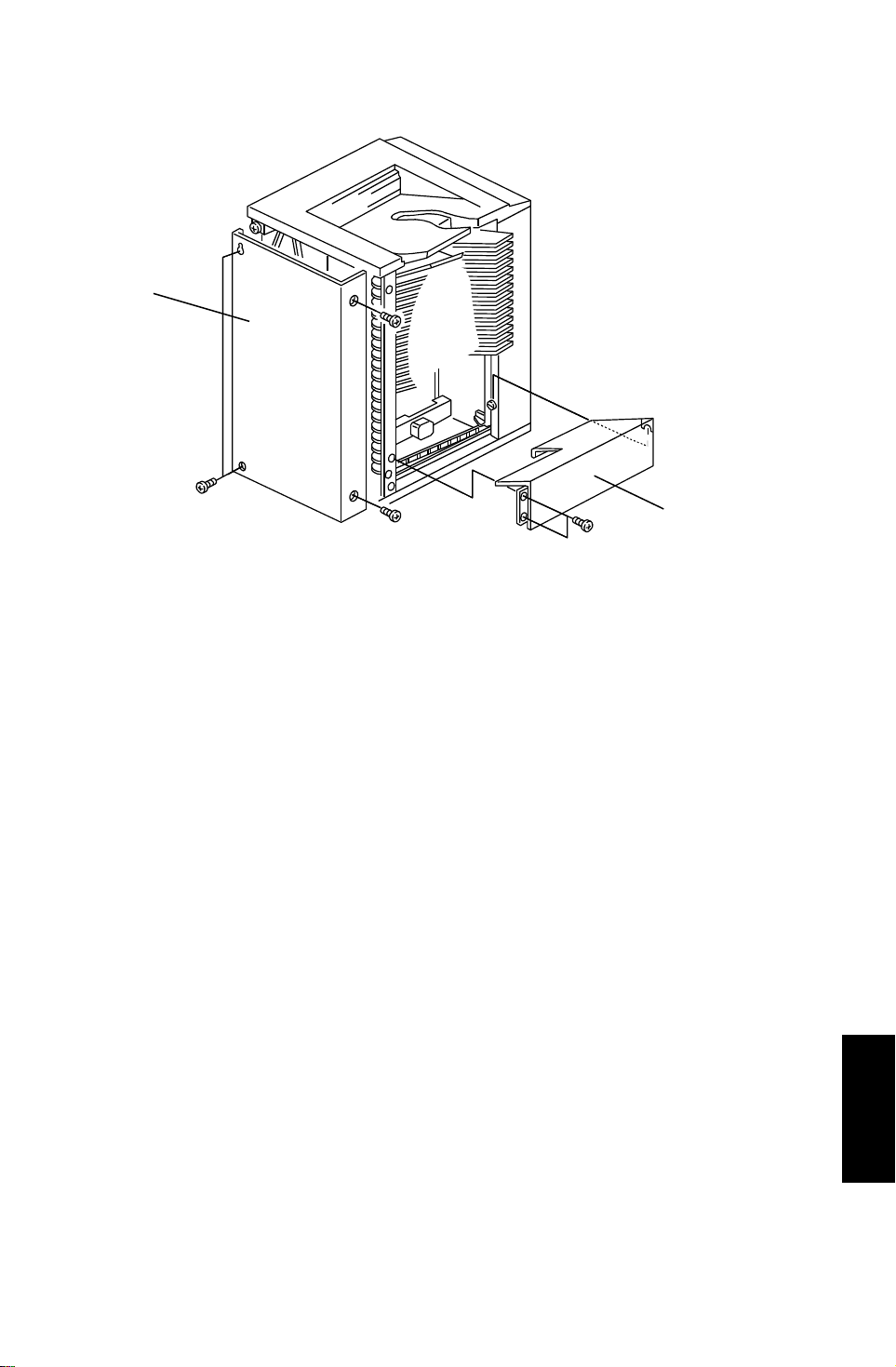
- Rear side -
[A]
[B]
1. Remove the rear cover [A] (4 screws).
2. Remove the bottom plate [B] (2 screws an d 1 ho ok).
35
(A377)
Sorter Stapler
Page 37
[D]
REPLACEMENTS AND ADJUSTMENTS 23 April 1993
16.2 STAPLER REMOVAL AND REINSTALLATI ON
[E][F]
[A]
[B]
[C]
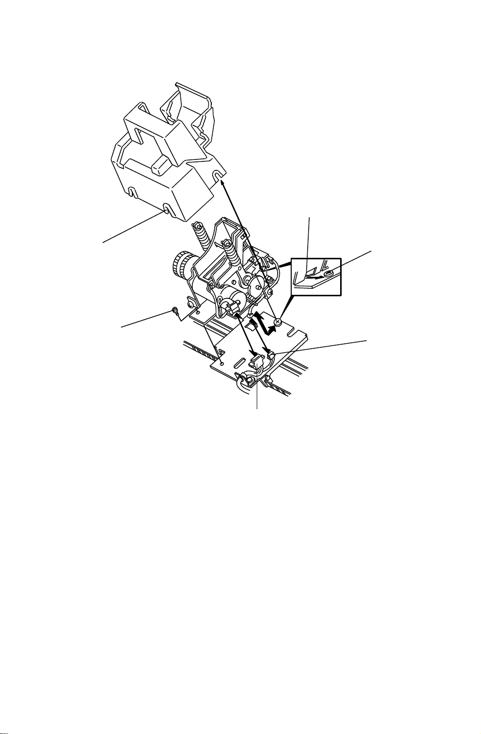
- Removal -
1. Remove the front inner cover. (Refer to Exte rior Cove r Removal.)
2. Remove the stapler unit (1 screw [A], 2 connectors).
- Installation -
1. Connect the two connectors [B] and [C].
2. Hook the cut out [D] on the stapler on the stepped screw [E].
3. Install the stapler unit(1 screw).
NOTE: All harnesses should be wired through the cut-out [F] on the
stapler cover. Do not pinch the harness between the cover and
staple unit.
The two connectors must be put inside the stapler cover.
4. Install the front inner cover (3 screws).
36
Page 38
23 April 1993 REPLACEMENTS AND ADJUSTMENTS
16.3 JOGGER PLATE REMOVAL AND INSTALLATI O N
[A]
[B]
[C]
[E]
[D]
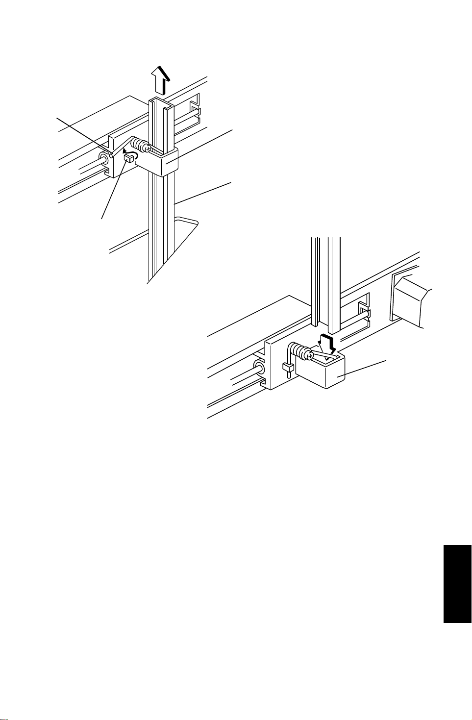
- Removal -
1. Remove the proof tray. (Refer to Exterior Cove r Re mova l.)
2. Release the spring [A] of the upper jogger holder [B], the n pull o ut the
jogger plate [C].
- Installation -
1. Insert the jogger plate through the upper holder [B].
2. Push down the jogger plate towa rds the lower holder [D].
3. Set the jogger plate in the lower holder [D].
4. Hook the spring [A] of the upper jog ge r h old er to the stopper [E].
(A377)
Sorter Stapler
37
Page 39
REPLACEMENTS AND ADJUSTMENTS 23 April 1993
16.4 BINS
- Removal -
[A]
[D]
[C]
[B]
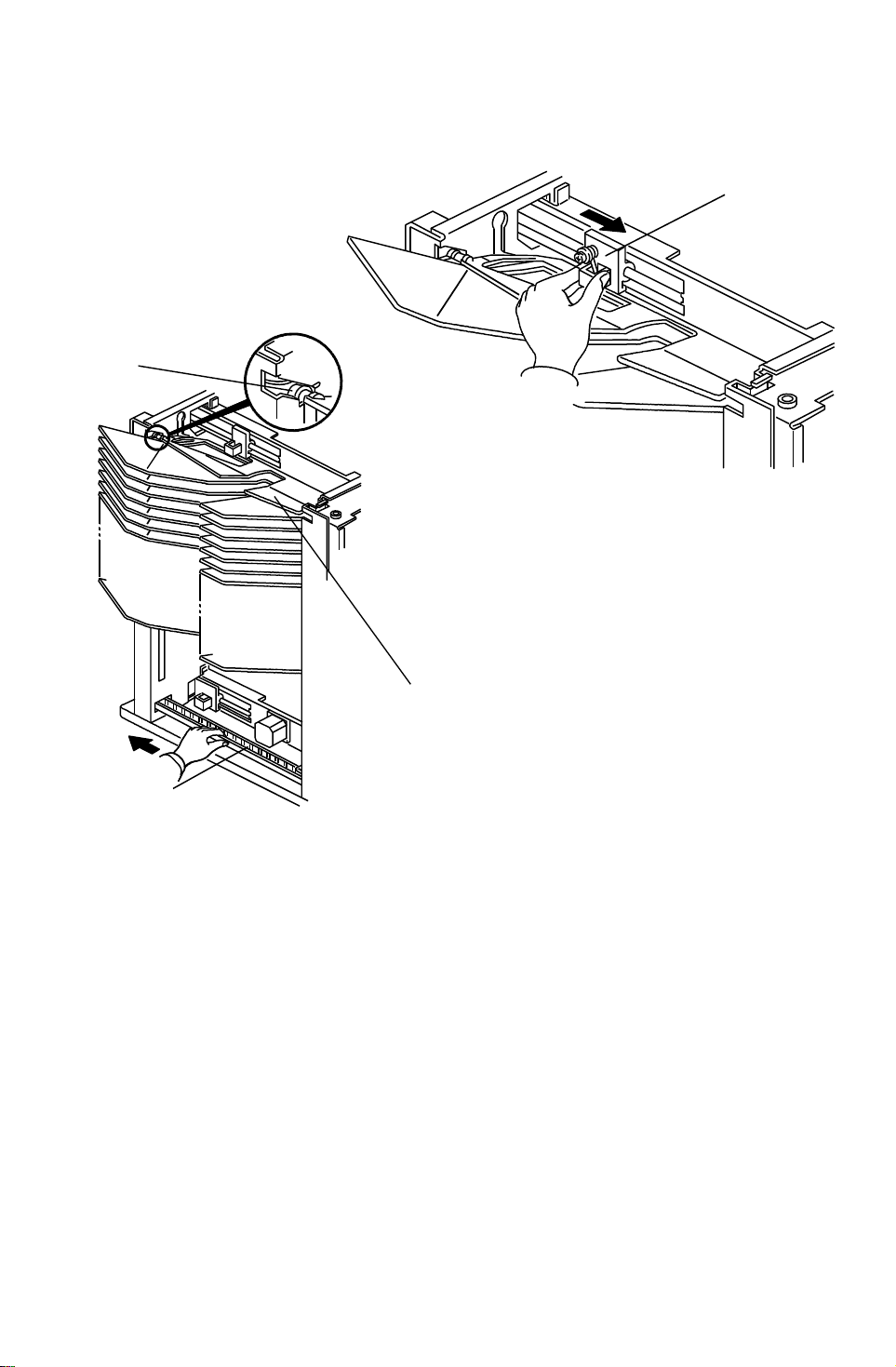
1. Remove the rear cover.
2. Raise all bins to the highest position by turning on DIP SW100 -1 on the
sorter main PCB then turn off th e main switch of the copie r.
3. Remove the jogger plate (refe r to Jog ge r P lat e Removal) then move the
upper jogger holder [A ] to the front side.
4. Remove the rear cover then remove the bo ttom plate to access the drive
belt. (Refer to Exterior Cove r Removal section.)
5. Manually rotate the helical wheel drive belt [B] and move up the top guid e
[C] until the three guide pins [D] rea ch th e to p of the helica l wh eel as
shown.
38
Page 40
[G]
23 April 1993 REPLACEMENTS AND ADJUSTMENTS
[D]
[B]
[A]
[C]
[F]
[H]
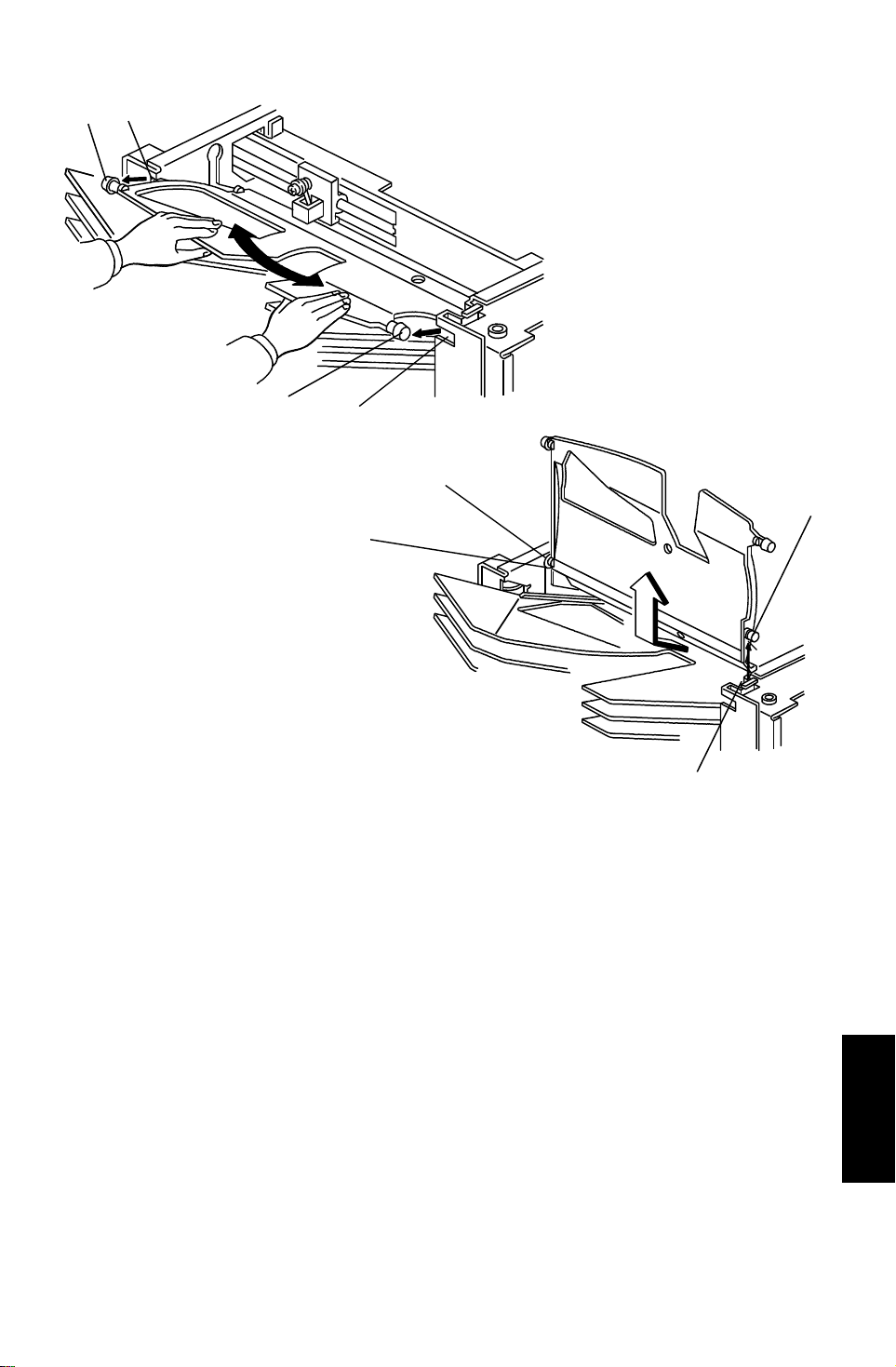
6. Remove the top guide by releasing th e pins [A] and [B] from cut-ou ts [C]
and [D] at the end of the bin guid e slots. Then remove the pins [E] and [F]
from cut-outs [G] and [H].
7. Move up the next bin to the top position by manually rotating the helical
wheel drive belt and remove it as in the to p gu ide removal procedure
(step 5 and 6).
[E]
8. Remove the other nineteen bin s by re pe at ing step.7.
39
(A377)
Sorter Stapler
Page 41
[E]
REPLACEMENTS AND ADJUSTMENTS 23 April 1993
- Installation -
[H]
[D]
[J]
[C]
[A]
[F]
[E]
[B]
[G]
[I]
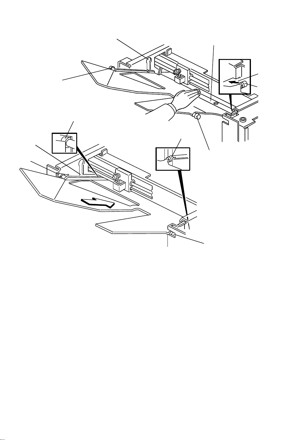
1. While holding the bin rear plate [A] st raig ht, insert rear right guide pin [B]
to the slot [C], then lower the re ar guide pin to the corner [D].
2. While still holding the bin rear plate straight, insert the front rig ht guide pin
[E] to guide slot [F].
3. Insert the other guide pins [G] and [H] to the slots [I] and [J].
40
Page 42
23 April 1993 REPLACEMENTS AND ADJUSTMENTS
[A]
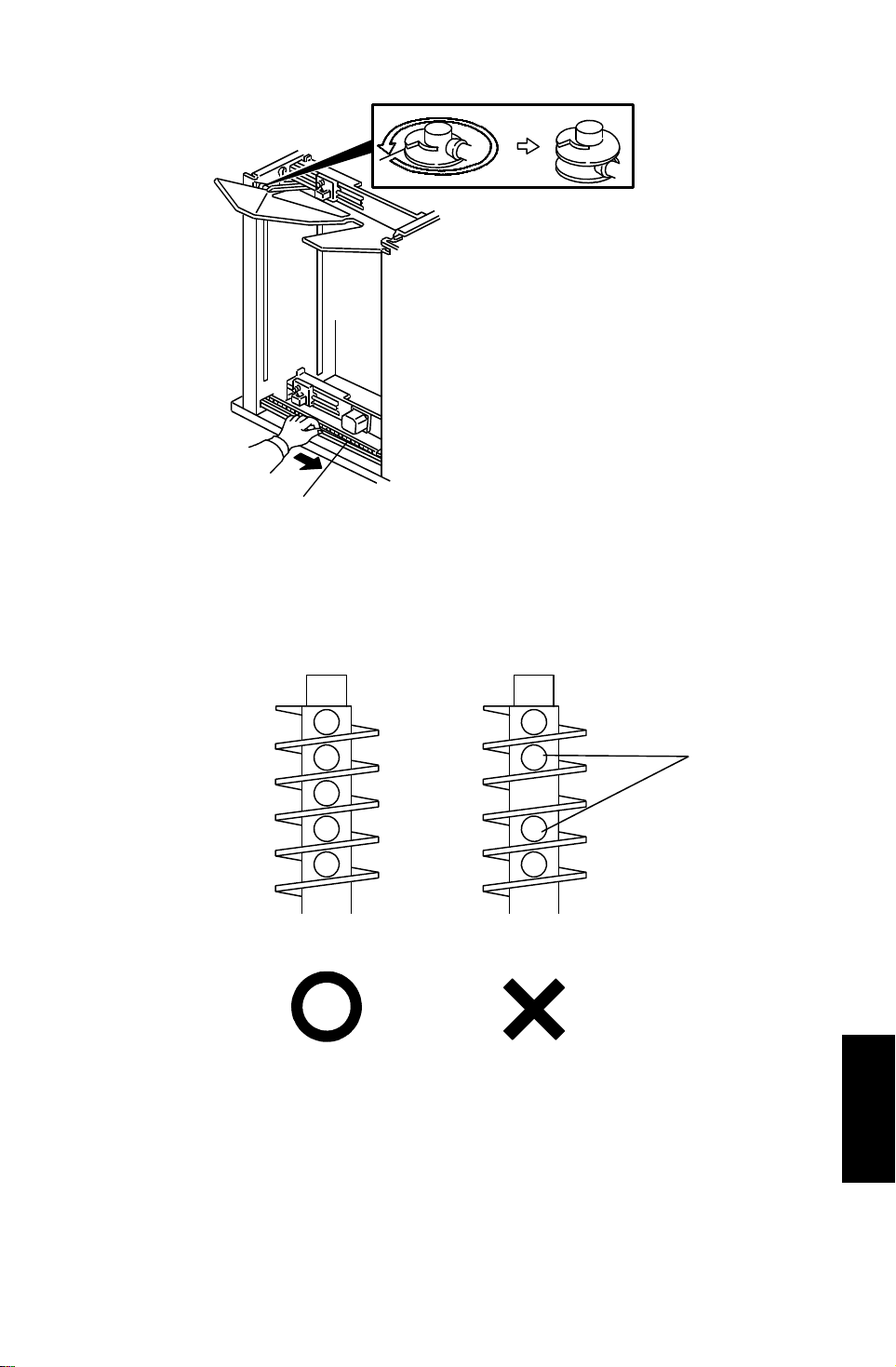
4. Manually rotate the helical wheel drive belt [A] and lower the bin.
NOTE: Before installing the next bin, rotate th e helical whe els on ly once.
Otherwise, the distance bet wee n the guide pins [B] become
uneven and the bin tilts
[B]
Good No good
5. Set all bins and the top cover by repe ating steps 1 to 4.
6. Re-install the jogger plate and all covers.
(A377)
Sorter Stapler
41
Page 43
[E]
REPLACEMENTS AND ADJUSTMENTS 23 April 1993
16.5 MAIN MOTOR REMOVAL
[A]
[B]
[F]
[D]
[C]
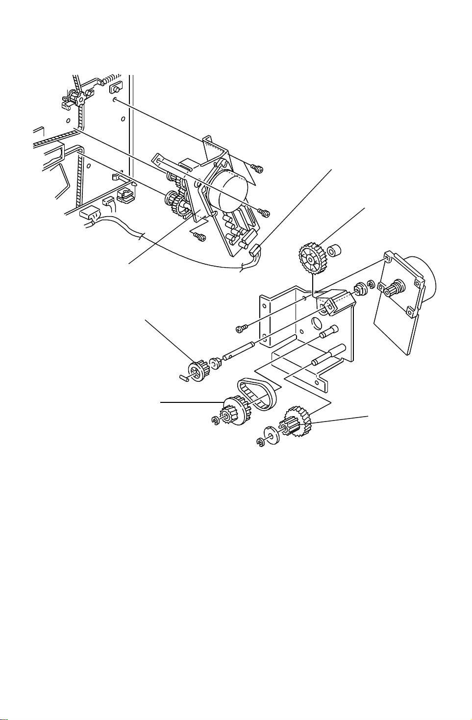
1. Remove the rear cover (4 screws).
2. Disconnect the connector [A].
3. Remove the main motor bracket [B] (4 screws) with th e main mo to r.
4. Remove all gears and pulleys [C] [D] [E] [F] (3 E-rings).
5. Remove the main motor (4 screws).
42
Page 44
[B]
23 April 1993 REPLACEMENTS AND ADJUSTMENTS
16.6 GRIP ASSEMBLY REMOVAL, AND GRIP SOLENOID
AND GRIP POSITIONI NG SOLENOID ADJUSTMENT
[A]
[C]
[B]
[D]
[C]
[D]
- Grip assembly removal -
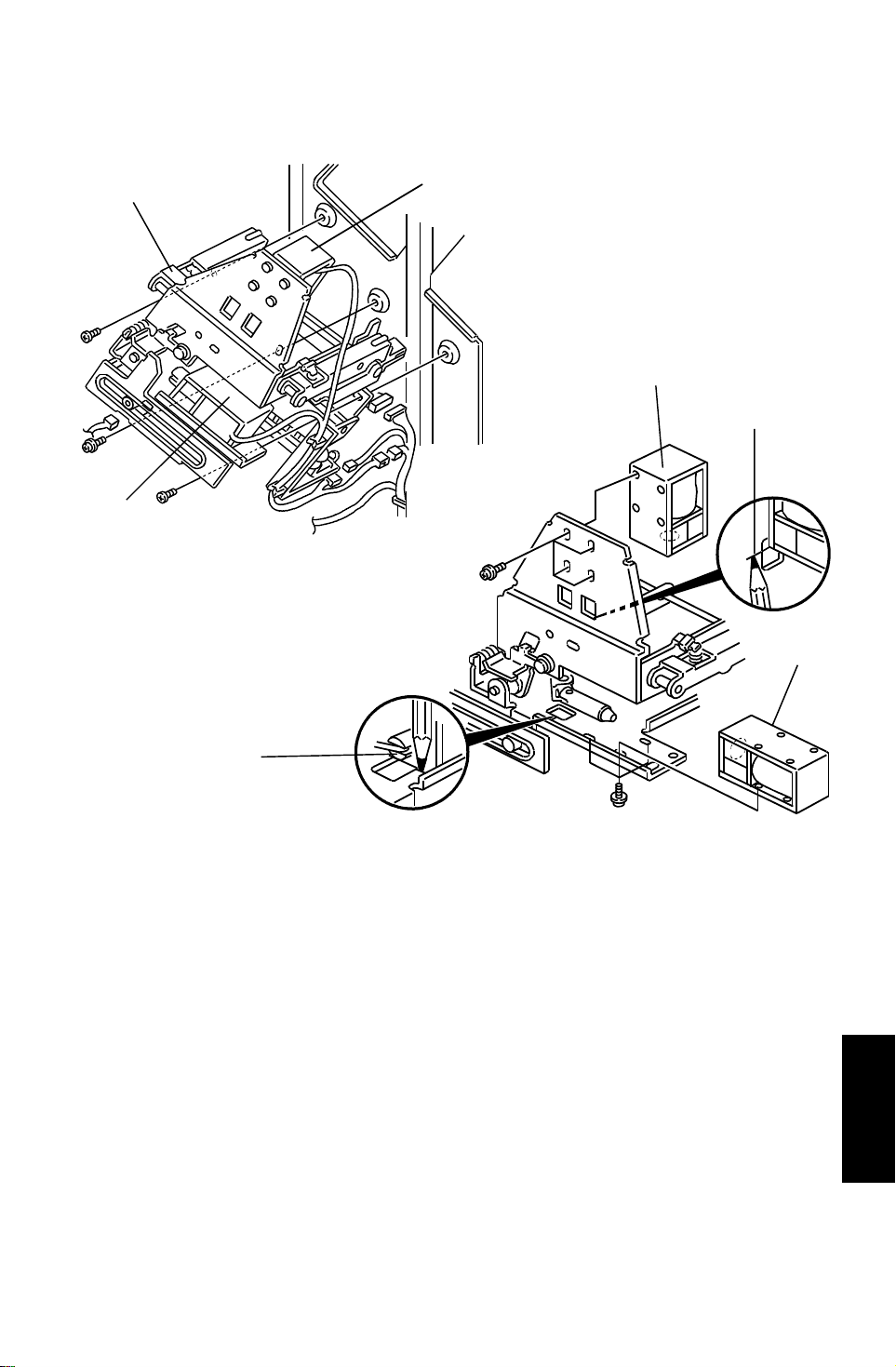
1. Open the front cover then remove the front inner cover. (Refer to Exterior
Cover Removal.)
2. Remove the grip assembly [A] (4 connectors, 3 screws).
3. Replace the grip solenoid [B] and the grip arm po sitio nin g solenoid [C].
- Grip solenoid [B] and the grip arm positioning sol enoid [C]
adjustments -
It is impossible to perform the fin e po sitio ning adjustments for both sole no ids
because magnets in both sole no ids pull t he plun ge r very strongly.
So, mark the original position of the solenoids and remove the solenoid. Then
place the solenoid at th e original position by refe rring to th e mark you made
[D] and tighten the screws (4 screws for the grip solenoid and 3 screws for
the grip arm positioning solenoid).
(A377)
Sorter Stapler
43
Page 45
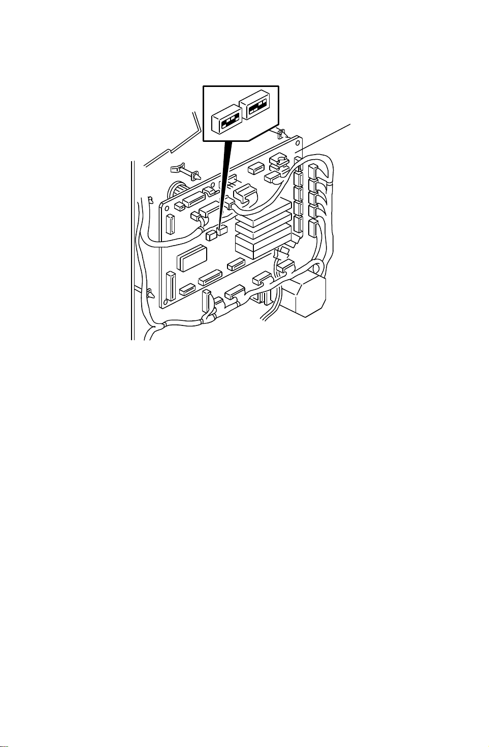
REPLACEMENTS AND ADJUSTMENTS 23 April 1993
16.7 MAIN CONTROL BOARD REPLACEMENT
[A]
1. Remove the rear cover (refer to Exterior Cover Remo val) then disconnect
all connectors (15 connectors an d 1 fiber op tics con ne cto r).
2. Remove the main control board [A ] (6 stu ds).
3. Install the new main control boa rd and set all connectors.
4. Position DIP SW101 and 102 as on the original main control board (DIP
SW 101 and 102 are for staple position adjustment).
5. Turn on the copier main switch then confirm the staple posit ion . If
incorrect, adjust the staple position. (Refer to the Staple Position
Adjustment.)
44
Page 46
23 April 1993 REPLACEMENTS AND ADJUSTMENTS
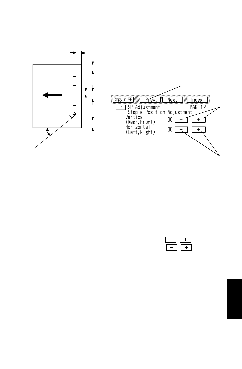
16.8 STAPLE POSITION ADJUSTMENT
ADJUSTMENT STANDARD:
a
a ~ c : 6 ± 3 mm
b: 6 ± 3 mm
c
c: 6 ± 3 mm
d: 66 ± 3 mm
d
e: 132 ± 2 mm
θ : 45 ± 5
[A]
e
b
θ
ADJUSTMENT
Both the vertical and the horizontal staple positions are adju sta ble as follo ws:
1. Enter SP mode as follows:
a. Press the clear modes key.
b. Enter 107.
c. Press and hold the clear/stop key for three seconds.
[B]
[C]
2. Touch the "SP Adjust men t" key.
3. Touch the Prev. key [A] four times to access page 12.
4. Adjust the vertical staple positio n by touching the , keys [B]
and the horizontal stap le po sitio n by touching the , keys [C].
NOTE: 0.5mm/step
45
(A377)
Sorter Stapler
Page 47
[B]
REPLACEMENTS AND ADJUSTMENTS 23 April 1993
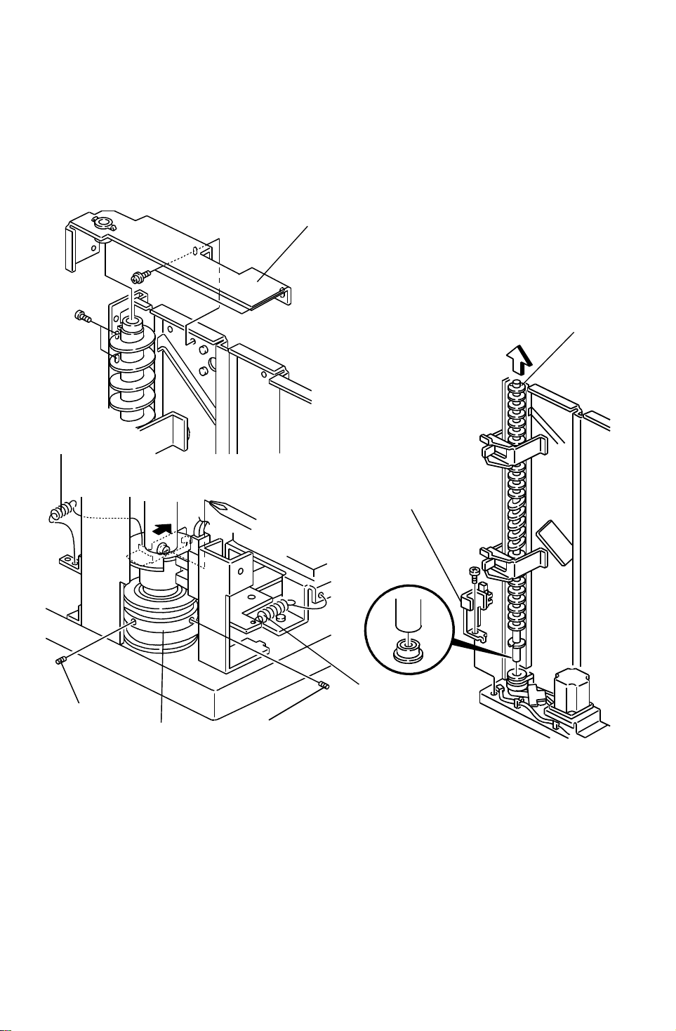
16.9 HELICAL WHEELS
- Removal -
Before removing the helical wheels, remove all bins and all exterior co vers.
(Refer to Exterior Cover and Bins Remova l.)
- Front Helical wheel -
[A]
[F]
[A]
[C]
[D]
[E]
[D]
1. Remove the bracket [A] (4 screws).
2. Remove the wheel sensor bracket [B] (1 screw).
3. Unhook the two springs [C].
4. Loosen the two Allen screws [D].
5. While holding the pulley [E] to keep it in position, remo ve th e helical
wheel [F].
46
Page 48
[B]
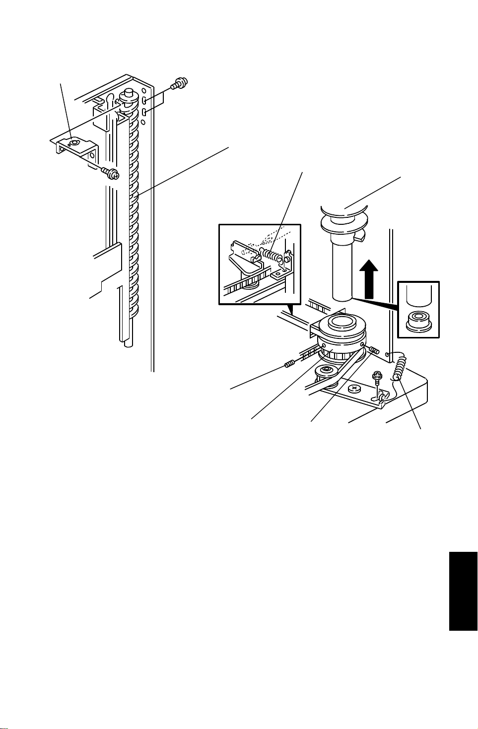
23 April 1993 REPLACEMENTS AND ADJUSTMENTS
- Rear Long Helical Wheel -
[A]
[E]
[F]
[D]
[E]
[D]
[C]
1. Remove the bracket [A] (3 screws).
2. Unhook the spring [B] at the front side and the spring [C] at the rear side.
3. Loosen the two Allen screws [D] on the drive pulley.
4. While holding the pulley [E] to keep it in position, remo ve th e helical
wheel [F].
(A377)
Sorter Stapler
47
Page 49
REPLACEMENTS AND ADJUSTMENTS 23 April 1993
- Rear Short Helical Wheel -
[A]
[E]
[D]
[B]
[C]
[D]
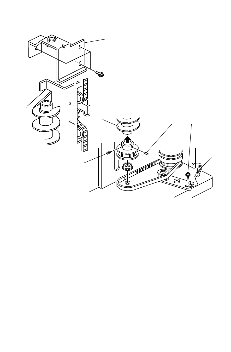
1. Remove the bracket [A] (3 screws).
2. Loosen the screw [B] then unhook th e te nsion spring [C].
3. Loosen the two Allen screws [D] on the drive pulley.
4. Remove the helical wheel [E].
48
Page 50
[G]
23 April 1993 REPLACEMENTS AND ADJUSTMENTS
- Installation -
NOTE: After installing the helical wheels, perform the helical wheels
alignment which is explaine d lat er.
- Rear Short Helical Wheel -
[F]
[D]
[E]
[F]
[K]
[J]
[H]
[A]
[B]
[C]
[I]
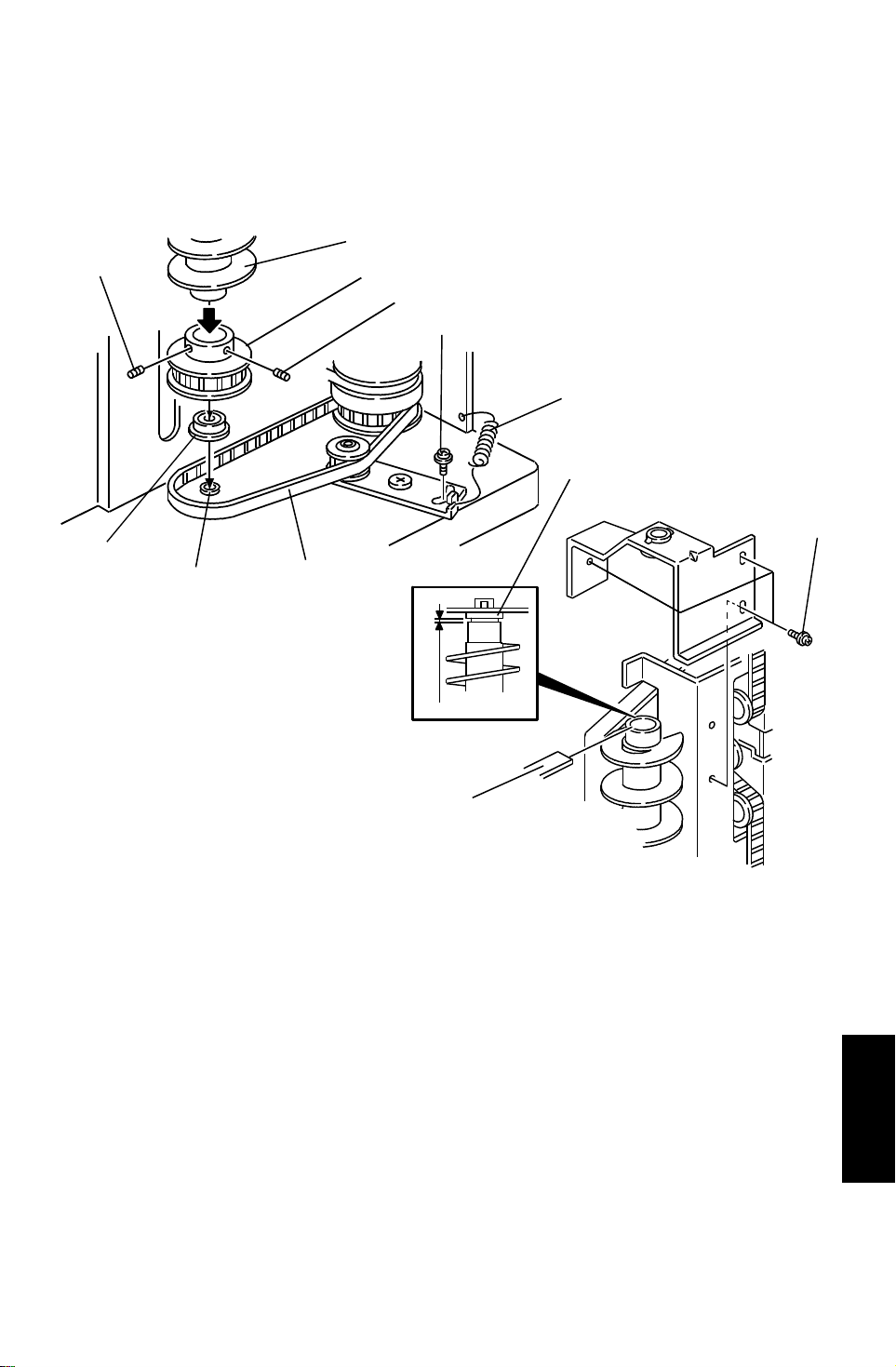
1. Place the bearing [A] on the notch [B] on the bott om plate then set the
timing belt-426XL [C] around the pulley.
2. Set the helical wheel [D] into the pulley [E]. Leave the Allen screws [F]
loosened.
3. Set the helical wheel [D] with the pulley [ E] on th e be arin g [A].
4. Set the bracket with the bushing [G] on top of the helical wheel then
install and slightly tighten the three screws [H].
5. Place a 0.4mm thickness gauge [I] between the helica l whee l and the
bushing [G] on the bra cket. While holding the bush ing down to the helical
wheel, tighten the three screws [H].
6. Set the tension spring [J], then tighten screw [K].
49
(A377)
Sorter Stapler
Page 51
[E]
[I]
[F]
REPLACEMENTS AND ADJUSTMENTS 23 April 1993
- Rear Long Helical Wheel -
[L]
[C]
[A]
[J]
[G]
[D]
[B]
[K]
0.4 mm
[E]
[H]
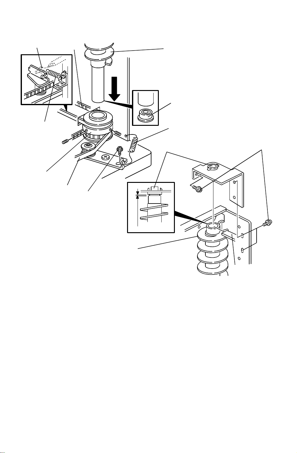
1. Place the bearing [A] on the notch on th e bo tt om plate then set timing
belt-426XL [B] and timing belt-918XL [C] aro und the pulley [D] .
2. Set the helical wheel [E] into the pulley [D] then set th e helical whe el on
the bushing [A].
3. Set the bracket with the bushing [F] on top of the helical wheel th en insta ll
and slightly tighten three screws [G].
4. Place a 0.4 mm thickness gauge [H] between the helical wheel [E] and
the bushing [F] on the bracke t. While holding the bushin g do wn to the
helical wheel, tighten the thre e screws [G ].
5. Hook tension springs [I] and [J] , th en tigh ten screws [K] and [L].
50
Page 52
[I]
23 April 1993 REPLACEMENTS AND ADJUSTMENTS
- Front Helical Wheel -
[G]
[C]
[E]
[B]
[D]
[F]
[A]
[J]
[K]
[K]
[H]
[O]
[H]
[L]
[N]
[M]
[I]
[P]
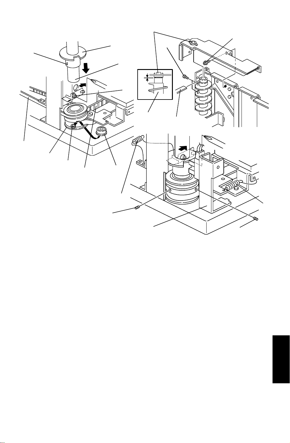
1. Place the bearing [A] on the notch [B] on th e bo tt om plate then set timing
belt-918XL [C] and timing belt-300XL [D] around the pulley.
2. Set the pulley [E] on the bearing. The direction of the pulley shou ld be as
shown in the illustration.
3. Set the helical wheel in the wheel sensor actuator [F]. Leave the Allen
screw [G] loosened.
4. Set the helical wheel [H] in the pulley [E]. Leave the Allen screws [I ]
loosened.
5. Set the bracket with a bushing [J] on top of the helical wheels then install
and slightly tighten the four screws [K].
6. Place a 0.4 mm thickness gauge [L] betwee n the helical wheel and the
bushing on the bracket . While holding the bushing down to th e he lical
wheel [H], tighten the four screws [K ].
7. Hook tension springs [M] and [N] then tighten the screw [O].
(A377)
Sorter Stapler
8. Install the wheel sensor bracket [P] .
51
Page 53
[E]
REPLACEMENTS AND ADJUSTMENTS 23 April 1993
- Alignment of the 3 Helical Wheel s -
[A]
[B]
[A]
[D]
[C]
[C]
[C]
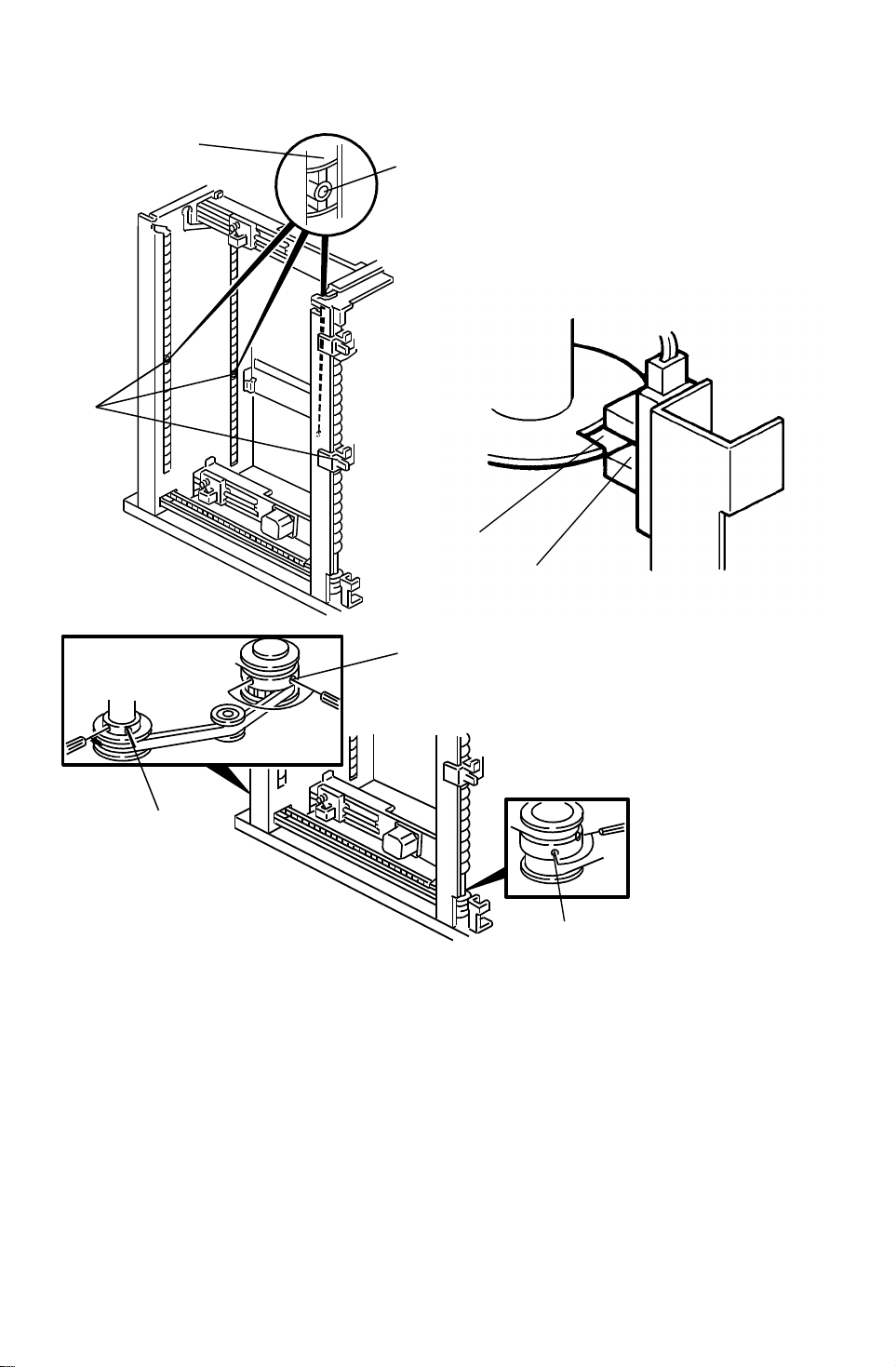
1. Confirm all belts are set correctly.
2. Align all holes [A] at the middle of the helical wheels at the center o f th e
bin guide slots [B], as shown.
3. In this condition, tighten all Allen screws [C] on the helical wheel drive
pulleys (2 Allen screws on each drive pulley).
4. In this condition, place the cut out [D] on the wheel sensor actua to r u nde r
the wheel sensor [E] then tighten the Allen screw on the wheel sen sor
actuator.
52
 Loading...