

Page 1

Technical Bulletin No. RTB-001
SUBJECT: Sorter Stapler Installation Procedure DATE: 15 May, ’92
PAGE: 1 of 1
PREPARED BY: M. Furusawa
CHECKED BY: T. Morita
CLASSIFICATION:
Action Required
Troubleshooting
Retrofit Information
When installing the sorter stapler, the procedure described below should be added to the
original installation procedure:
Service manual:
Sorter Stapler - 13. Installation Procedure (page 26)
Steps added between 5. and 6.
[Y]
[X]
Revision of service manual
Information only
Other
FROM: Copier Technical Support Section
MODEL: A7 Series
• Remove the cover plate [X] from the sorter adapter (2 screws).
• Install the upper exit guide mylar [Y] on the sorter adapter and fix it
with the cover plate as shown.
NOTE: This mylar is required to prevent some brands of paper, which curl too much after
fusing, from jamming at the sorter stapler entrance area.
The upper exit guide mylar (P/N A3666060) has been enclosed as an accessory in
the machine box from the first mass production.
We will issue an M/B for the upper exit guide mylar later.
Page 2
Technica l Bulletin No . RTB-01 0
[B]
SUBJECT: Sorter Stapler ( A366) Gripper Operation DATE: Feb . 15, ’ 9 3
PAGE: 1 o f 2
PREPARED BY: M . Fu ru saw a
FROM: Copier Technical Support Section
CHECKED BY: T. Ito
CLASSIFICATION:
Action Required
Troubleshooting
Retrofit Information
Revision of service manual
Information only
Other
MODEL:
A7 Series
(A069/A073/A074)
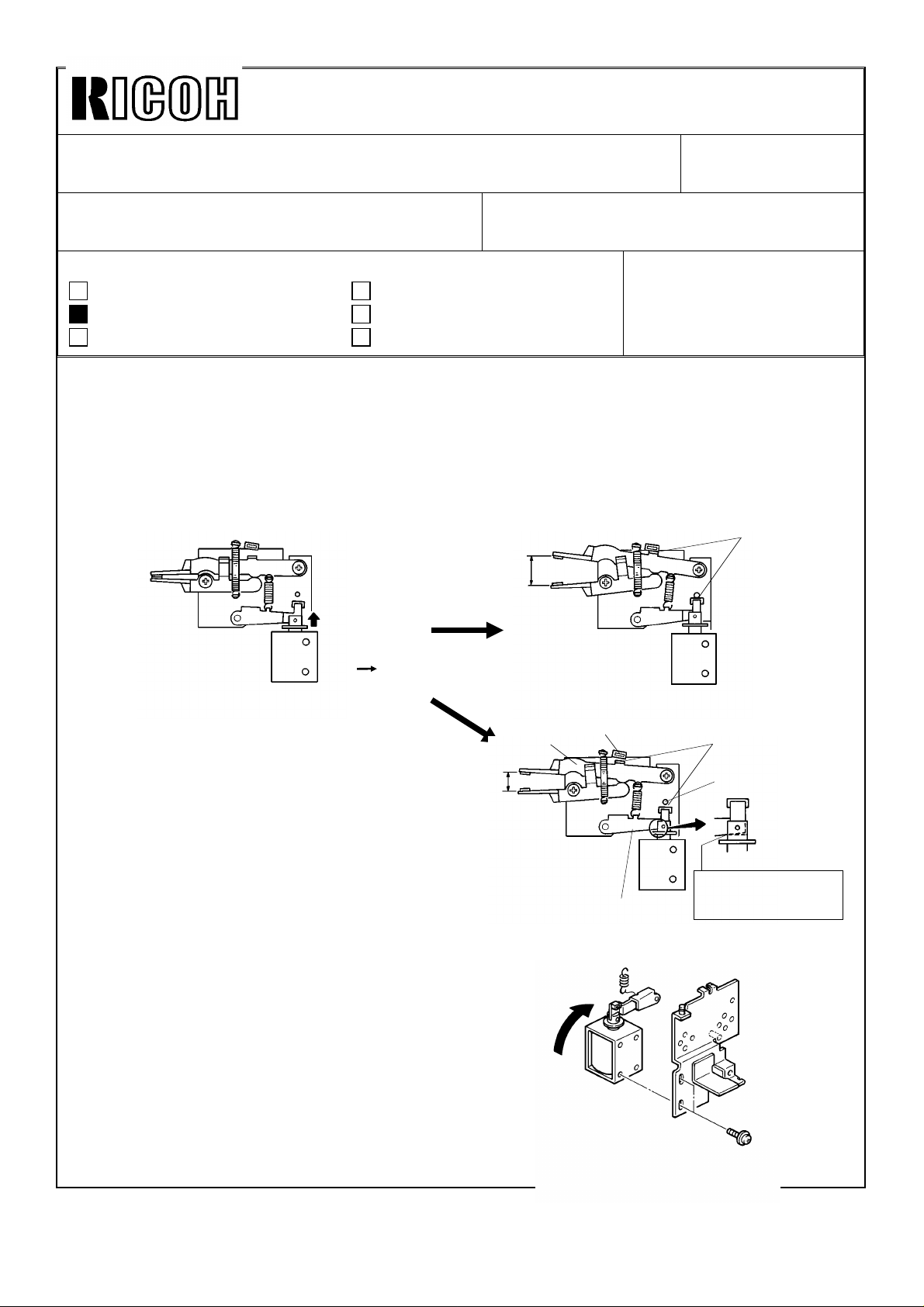
[PHENOMENON]
During stapling operation, the gripper pushes the bottom cop y out of position.
[CAUSE]
The grippers are not opening wide enough.
24 - 25 mm
SOL.
ON OFF
[OK]
No Gap
When t he g rip s o leno id tu rn s o ff, th e
grippers should open wide enough.
If th e so leno id p lu ng er is c aug h t b y t he
solenoid arm [ A], the arm and the upper
gripper [B] cannot reach the stoppers
[C,D]. Refer to the figure [NG].
[ACTION]
1. Loosen the screws securing the grip
so len o id .
Then tighten the screws while turning the
grip solenoid, as shown by the arrow at the
right.
NOTE: Make sure that the solenoid stroke is
maintained for 2.5 ± 0.5 mm.
20 mm
[NG]
[D]
[A]
Gap
[C]
Plunger is caught at
this point and stops.
Page 3

Technica l Bulletin No . RTB-01 0
SUBJECT: Sorter Stapler ( A366) Gripper Operation DATE: Feb . 15, ’ 9 3
PAGE: 2 o f 2
2. If there still be a gap "A" after performing step 1,
lengthen the solenoid arm spring [E] as shown.
NOTE: Be careful not to lengthen the spring too much,
or the spring will not hook the gripper properly.
Leng then by "A" as sho wn.
With the above two actions the width
of the gripper opening can be
adjusted by about 5 mm.
x
A= Gap
[E]
x+ A
 Loading...