

Page 1

3,000-SHEET FINISHER
(Machine Code: B302)
Page 2
22 October 1999 SPECIFICATIONS
1. OVERALL MACHINE INFORMATION
1.1 SPECIFICATIONS
The punch unit is an option for this machine.
Paper Size: No punch mode
Shift Tray: A3 to A5/DLT to HLT
Upper Tray: A3 to A5, A6 lengthwise, B6 lengthwise/
DLT to HLT
Punch mode
2 holes: A3 to A5/DLT to HLT
3 holes: A3, B4, A4 sideways, B5 sideways
DLT, LT sideways
4 holes (Europe):A3 to A5
DLT to LT, HLT sideways
4 holes (North Europe): A3 to B5, A5 sideways
DLT to LT, HLT sideways
Staple Mode
A3 to B5/DLT to LT
Paper Weight: No punch mode
2
No staple mode: 52 g/m
~ 216 g/m2, 14 ~ 42 lb
Staple mode: 64 g/m2 ~ 80 g/m2, 17 ~ 21 lb
Punch mode
2 holes: 52 g/m2 ~ 163 g/m2, 14 ~ 42 lb
3 holes: 52 g/m2 ~ 163 g/m2, 14 ~ 42 lb
4 holes: 52 g/m2 ~ 128 g/m2, 14 ~ 34 lb
Paper Capacity: Shift tray/no staple mode (80 g/m2, 20 lb):
Punch mode No punch mode
B5 sideways
A4 sideways
LT sideways
Other sizes 1,500 sheets 1,500 sheets
2,500 sheets 3,000 sheets
Shift tray/staple mode/punch mode (80 g/m2, 20 lb):
Pages/set Sets
B5 sideways
A4 sideways
LT sideways
Other sizes
2 to 9 150
10 to 80 200 to 30
2 to 9 100
10 to 40 150 to 30
Options
B302-1
Page 3
SPECIFICATIONS 22 October 1999
Shift tray/staple mode/no punch mode (80 g/m2, 20 lb):
Pages/set Sets
B5 sideways
A4 sideways
LT sideways
Other sizes
2 to 9 150
10 to 100 200 to 30
2 to 9 150
10 to 50 150 to 30
Upper tray (80 g/m2, 20 lb):
Punch mode No punch mode
A4/LT or smaller 400 sheets 500 sheets
Larger than A4/LT 200 sheets 250 sheets
Stapler Capacity (pages/set, 80 g/m2, 20 lb paper):
Punch mode No punch mode
B5 sideways
A4 sideways
LT sideways
Other sizes 40 sheets 50 sheets
80 sheets 100 sheets
Staple Position: 4 positions
1-staple: 3 positions (Front, Rear, Rear-Oblique)
2-staple: 1 position
Staple Replenishment: Cartridge (5,000 staples)
Power Source: 24 Vdc (from copier)
Power Consumption: 120 W
Weight: 60 kg
Size (W x D x H): 800 mm x 730 mm x 980 mm
B302-2
Page 4
22 October 1999 MECHANICAL COMPONENT LAYOUT
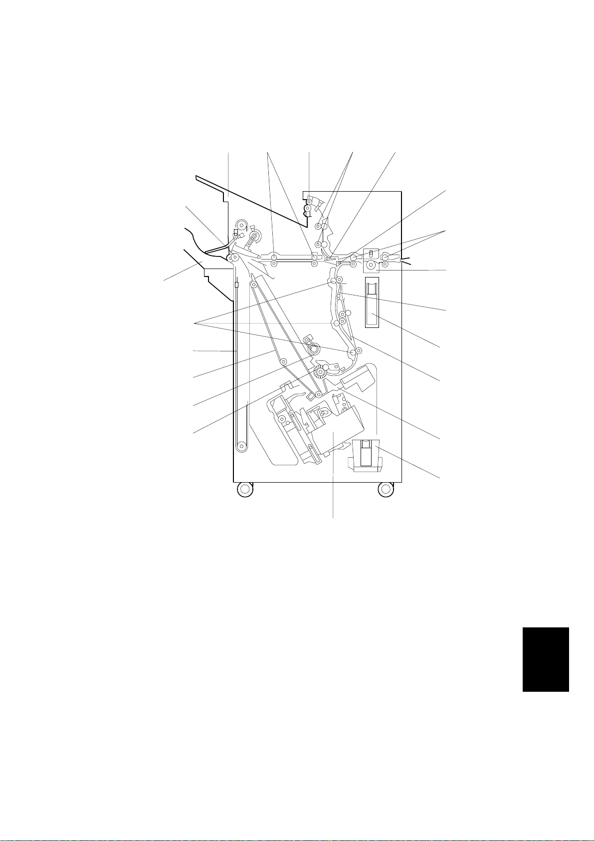
1.2 MECHANICAL COMPONENT LAYOUT
20
21
19
18
17
16
15
1 2 5
3
4
6
7
8
9
10
11
12
1. Upper Tray
2. Middle Transport Rollers
3. Upper Tray Exit Roller
4. Upper Transport Rollers
5. Tray Junction Gate
6. Stapler Junction Gate
7. Entrance Rollers
8. Punch Unit
9. Pre-stack Junction Gate
10. Punch W aste Hopper
11. Pre-stack Tray
13
14
B302V500.WMF
12. Stack Plate
13. Staple W aste Hopper
14. Stapler
15. Alignment Brush Roller
16. Positioning Roller
17. Stack Feed-out Belt
18. Shift Tray Drive Belt
19. Lower Transport Rollers
20. Shift Tray
21. Shift Tray Exit Roller
Options
B302-3
Page 5

ELECTRICAL COMPONENT DESCRIPTION 22 October 1999
1.3 ELECTRICAL COMPONENT DESCRIPTION
Symbol Name Function
Motors
M1
M2
M3 Jogger Moves the jogger fence.
M4 Stack Plate Drives the stack plate.
M5 Stapler Moves the staple unit from side to side.
M6 Stapler Rotation Rotates the stapler 45 degrees.
M7 Staple Hammer Drives the staple hammer.
M8 Stack Feed-out Drives the stack feed-out belt.
M9 Exit Guide Opens and closes the upper exit guide.
M10 Shift Tray Exit Drives the exit roller for the shift tray.
M11 Shift Moves the shift tray from side to side.
M12 Shift Tray Lift Moves the shift tray up or down.
M13 Punch Drives the punch shaft and roller.
Upper Transport Drives the entrance rollers, the middle and upper
transport rollers, and upper tray exit roller.
Lower Transport
Drives the lower transport rollers, the alignment brush
roller, and the positioning roller.
Sensors
S1
S2
S3
S4 Jogger Fence HP Detects the home position of the jogger fence.
S5 Stapler Tray Paper Detects the copy paper in the stapler tray.
S6 Stack Plate HP Detects the home position of the stack plate.
S7
S8
S9 Staple Hammer HP Detects the home position of the staple hammer.
S10 Cartridge Set Detects the staple cartridge in the stapler.
S11 Staple End Detects the staples in the cartridge.
S12
S13
S14 Exit Guide Open Detects whether the guide plate is opened or not.
S15 Shift Tray Exit Checks for misfeeds at the shift tray.
S16
S17
S18 Upper Tray Exit Checks for misfeeds at the upper tray.
Entrance Detects the copy paper entering the finisher and
checks for misfeeds.
Pre-stack Tray
Paper
Stapler Tray
Entrance
Stapler HP Detects the home position of the staple unit for sideStapler Rotation HP Detects the home position of the stapler unit for 45-
Staple Waste
Hopper
Stack Feed-out BeltHPDetects the home position of the stack feed-out belt.
Stack Height 1 Detects when the top of the copy paper stack in the
Stack Height 2 Detects when the top of the copy paper stack in the
Determines when to turn off the pre-stack paper
stopper solenoid.
Detects the copy paper entering the stapler tray and
checks for misfeeds.
to-side movement.
degree rotation.
Detects when the staple waste hopper is full.
shift tray is at the correct position.
shift tray has become too high.
B302-4
Page 6

22 October 1999 ELECTRICAL COMPONENT DESCRIPTION
Symbol Name Function
S19
S20
S21
S22
S23
S24
Upper Tray Paper
Limit
Shift Tray Half-turn Detects the return position for side-to-side movement
Shift Tray Lower
Limit 1
Shift Tray Lower
Limit 2
Punch Waste
Hopper
Punch HP Detects the home position of the punch shaft and
Detects when the paper stack height in the upper tray
is at its upper limit.
of the shift tray.
Detects when the shift tray is nearly at its lower limit.
Detects when the shift tray is at its lower limit.
Detects when the punch waste hopper is full and
detects when the punch tray is set.
roller.
S25 Stapler Return Detects the on timing of the stapler return solenoid.
Switches
SW1 Front Door Safety Cuts the dc power when the front door is opened.
SW2
Shift Tray Upper
Limit
Cuts the power to the shift tray lift motor when the
shift tray position is at its upper limit.
Solenoids
SOL1
Stapler Junction
Gate
Drives the stapler junction gate.
SOL2 Tray Junction Gate Drives the tray junction gate.
SOL3
SOL4
Pre-stack Junction
Gate
Pre-stack Paper
Stopper
Drives the pre-stack junction gate.
Drives the pre-stack paper stopper.
SOL5 Positioning Roller Moves the positioning roller against the stapling tray.
SOL6
Stapler Return
Returns the stapler to its guide from the user
operation position.
PCBs
PCB1
PCB2
Main
Punch Passes signals between the punch unit and the
Controls the finisher and communicates with the
copier.
finisher main board.
B302-5
Options
Page 7
DRIVE LAYOUT22 October 1999
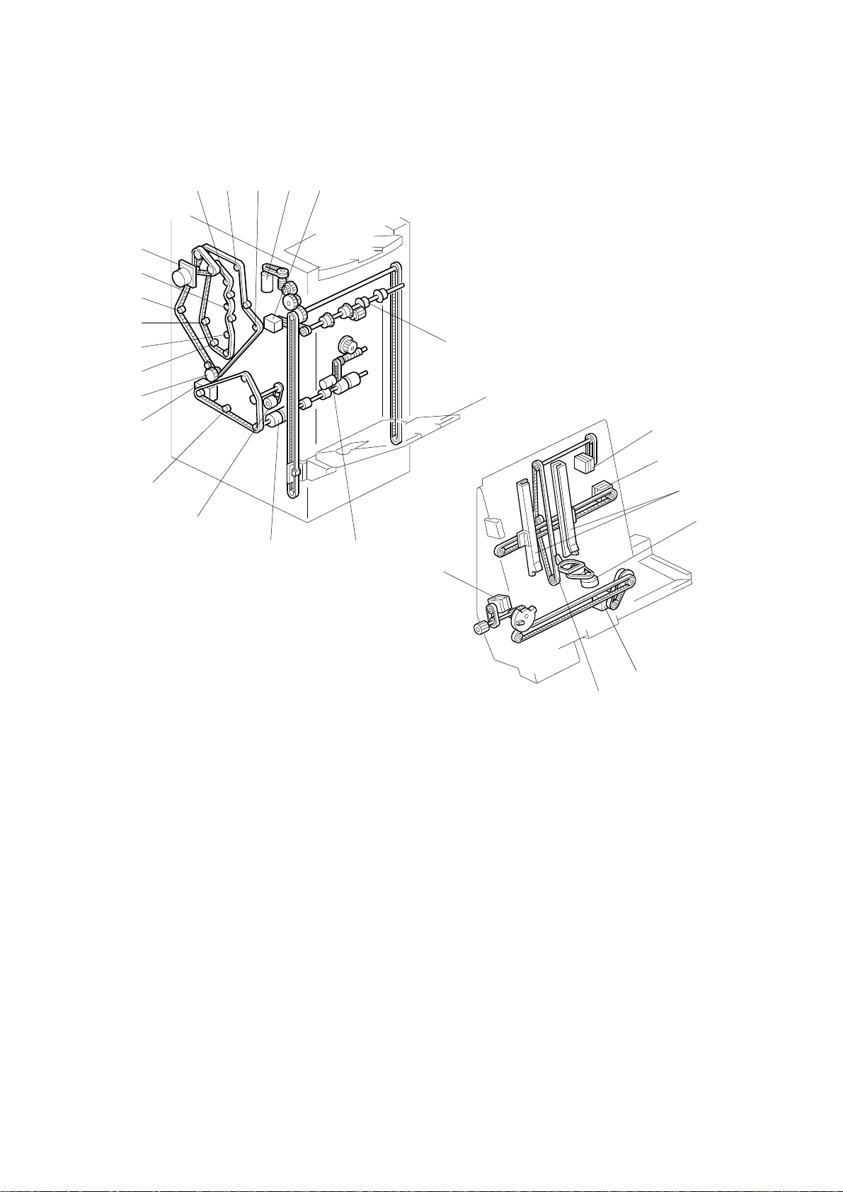
1.4 DRIVE LAYOUT
1 2 3 4 5
19
18
17
16
15
14
6
13
12
11
10
B302V503.WMF
1. Upper Transport Roller 2
2. Upper Tray Exit Roller
3. Lower Transport Roller 2
4. Shift Tray Lift Motor
5. Shift Tray Exit Motor
6. Shift Tray Exit Roller
7. Shift Tray
8. Shift Motor
9. Staple Tray Exit Roller
10. Positioning Roller
11. Lower Transport Roller 3
12. Lower Transport Motor
13. Lower Transport Rollers 2
9 8
7
20
21
22
23
26
24
25
B302V504.WMF
14. Lower Transport Roller 1
15. Transport Roller 1
16. Entrance Roller 2
17. Entrance Roller 1
18. Upper Transport Roller 1
19. Upper Transport Motor
20. Stack Feed-out Motor
21. Jogger Motor
22. Jogger Fence
23. Stack Plate Motor
24. Stapler Motor
25. Stack Feed-out Belt
26. Stapler Rotation Motor
B302-6
Page 8

22 October 1999 TRAY AND STAPLER JUNCTION GATE
2. DETAILED DESCRIPTIONS
2.1 TRAY AND STAPLER JUNCTION GATE
- Upper Tray Mode -
[D]
[A]
[C]
[B]
- Sort/Stack Mode - - Staple Mode -
[A]
[C]
B302D505.WMF
[B]
[D]
B302D506.WMF
[A]
[C]
B302D507.WMF
[D]
[B]
Depending on the finishing mode, the copies are directed up, straight through, or
down by the combination of the tray junction gate [A] and stapler junction gate [B].
These gates are controlled by the tray junction gate solenoid [C] and stapler
junction gate solenoid [D].
Upper Tray Mode
The stapler tray junction gate solenoid remains off and the tray junction gate
solenoid turns on. The copies go up to the upper tray.
Sort/Stack Mode
The tray junction gate solenoid and the stapler junction gate solenoid remain off.
The copies are sent to the shift tray directly.
Staple Mode
The stapler junction gate solenoid turns on. The copies go downwards to the
jogger unit.
B302-7
Options
Page 9
PAPER PRE-STACKING 22 October 1999
2.2 PAPER PRE-STACKING
[A]
[B]
[E]
[F]
[C]
[D]
B302D000.WMF
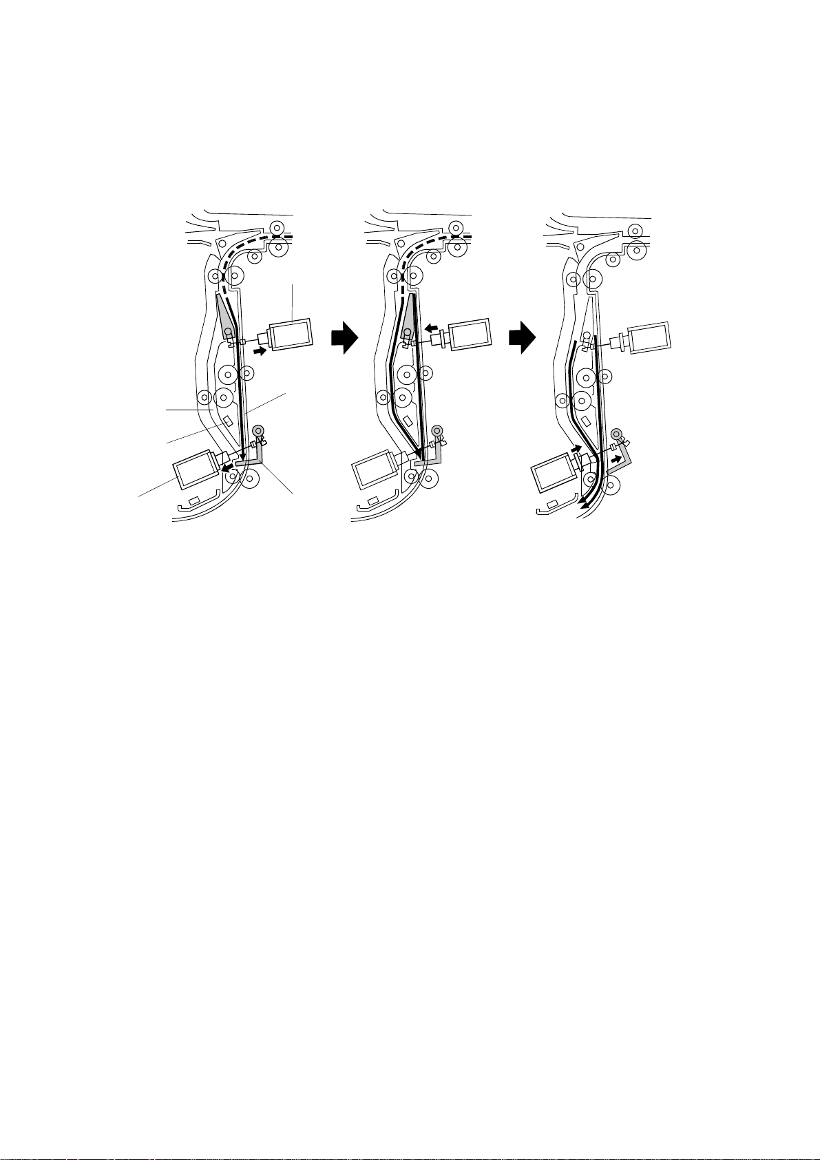
This mechanism improves productivity in staple mode. It is only used when copying
on A4, LT, or B5 (all sideways).
During stapling, the copier has to wait. This mechanism reduces the wait by
holding the first two sheets of a job while the previous job is still being stapled. It
only works during the second and subsequent sets of a multi-set copy job.
The pre-stack junction gate solenoid [A] turns on about 230 ms after the 1st sheet
of paper turns on the entrance sensor, and this directs the sheet to the pre-stack
tray [B]. (This sheet cannot be fed to the stapler yet, because the first set is still
being stapled.) The pre-stack paper stopper solenoid [C] turns on about 680 ms
after the 1st sheet turns on the entrance sensor. The pre-stack paper stopper [D]
then stops the paper.
The pre-stack junction gate solenoid turns off 450 ms after the trailing edge of the
1st sheet passes through the entrance sensor, and the 2nd sheet is sent to the
paper guide [E]. The pre-stack paper stopper is released about 50 ms after the 2nd
sheet turns on the pre-stack stopper sensor [F], and the two sheets of copy paper
are sent to the stapler tray. All sheets after the 2nd sheet go to the stapler tray via
the paper guide [E].
B302-8
Page 10
22 October 1999 JOGGER UNIT PAPER POSITIONING
2.3 JOGGER UNIT PAPER POSITIONING
[C]
[A]
[G]
[F]
[E]
[B]
[D]
[I]
[H]
[J]
B302D508.WMF
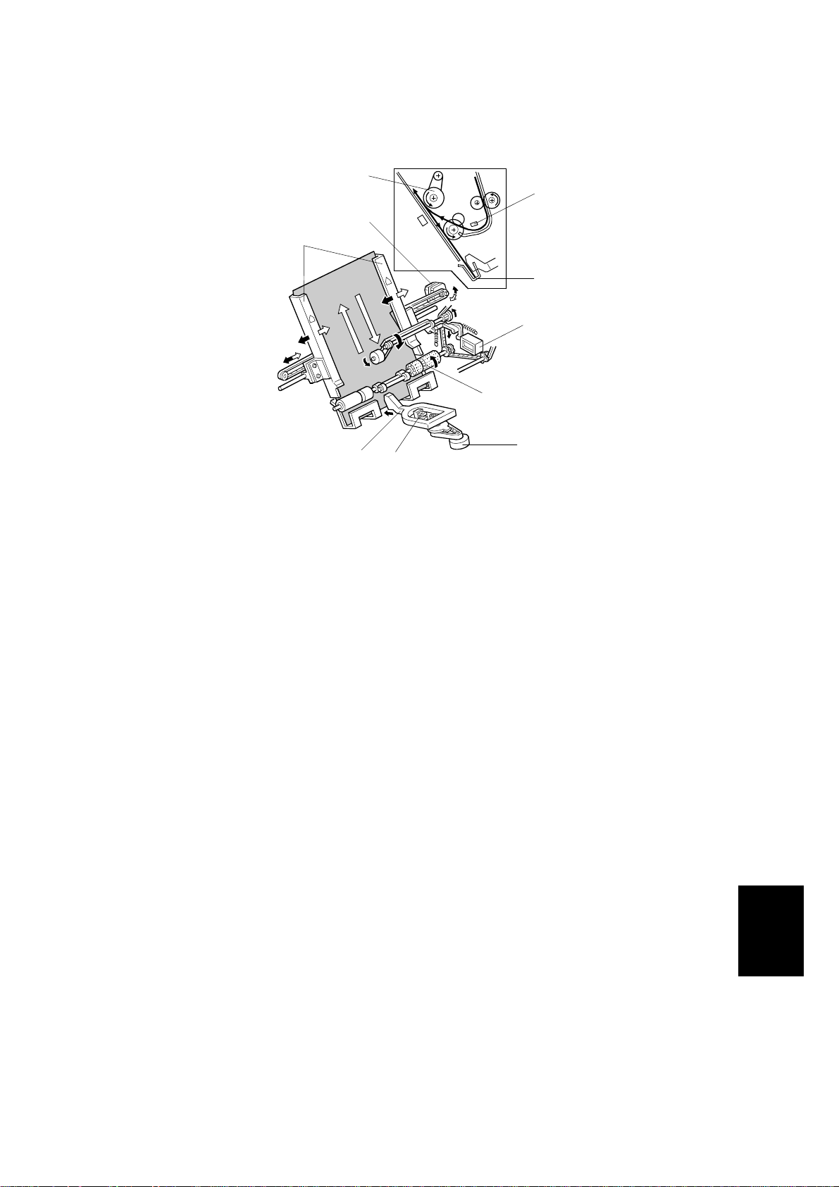
In staple mode, each sheet of copy paper is vertically and horizontally aligned
when it arrives in the jogger unit.
Vertical Paper Alignment
Approximately 60 ms after the trailing ed ge of the copy passes the staple tray
entrance sensor [A], the positioning roller solenoid [B] is energized to push the
positioning roller [C] into contact with the paper. The positioning roller and
alignment brush roller [D] rotate to push the paper back and align the trailing edge
of the paper against the stack stopper [E].
Horizontal Paper Alignment
When the prin t key is pressed, the jogger motor [F] turns on and the jogger fences
[G] move to the waiting position, which is approximately 7 mm wider on both sides
than the selected paper.
When the tr ailing edge of the paper passes the staple unit entra nce sensor, the
jogger motor turns on for approximately 32 ms (4.7 mm) to move the jogger fences
approximately 5 mm towards the paper. After a short time, the jogger motor turns
on again approximately 18 ms (3.0 mm) for the horizontal paper alignment then
goes back to the waiting position.
Paper Stack Correction
After the paper is aligned in the stapler tray, the stack plate motor turns [H] on for
short time to correct the paper stack and the stack plate [I] push the paper against
the staple tray.
When the next copy pape r turns on the s tapler tray entrance sensor, the stack
plate motor turns on gain to return to its home position. The home position is
detected by stack plate HP sensor [J].
B302-9
Options
Page 11
STAPLER UNIT MOVEMENT 22 October 1999
2.4 STAPLER UNIT MOVEMENT
[A]
[B]
[C]
B302D513.WMF
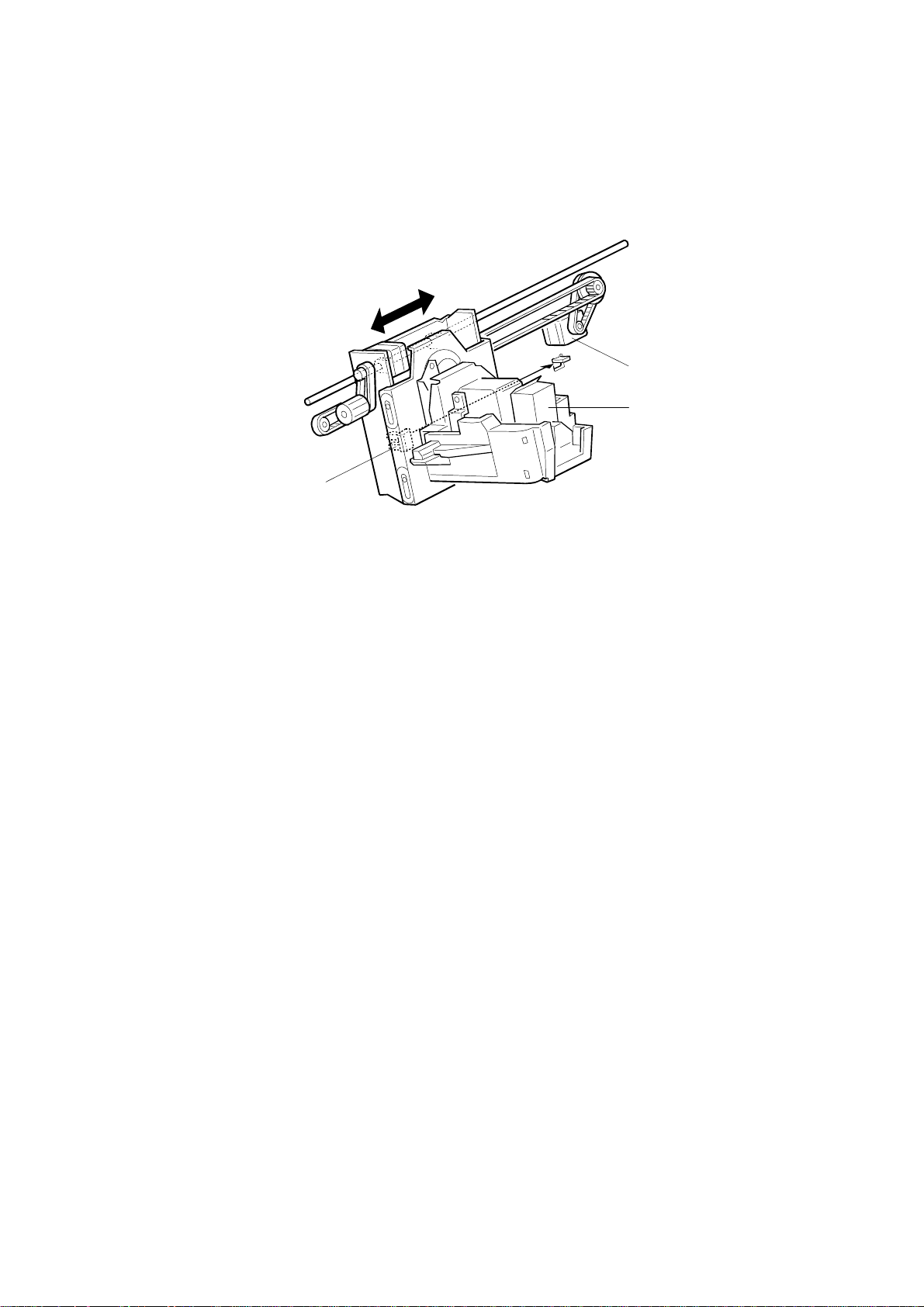
Side-to-Side
The stapler motor [A] moves the stapler [B] from side to side. After the start key is
pressed, the stapler moves from its home position to the stapling position.
If two-staple-position mode is selected, the stapler moves to the front stapling
position first, then moves to the rear stapling position. However, for the next copy
set, it staples in the reverse order (at the rear side first then at the front side).
After the job is completed, the stapler moves back to its home position. This is
detected by the stapler HP sensor [C].
B302-10
Page 12
22 October 1999 STAPLER UNIT MOVEMENT
[A]
[B]
[F]
B302D514.WMF
[D]
[E]
B302D523.WMF
[C]
B302D515.WMF
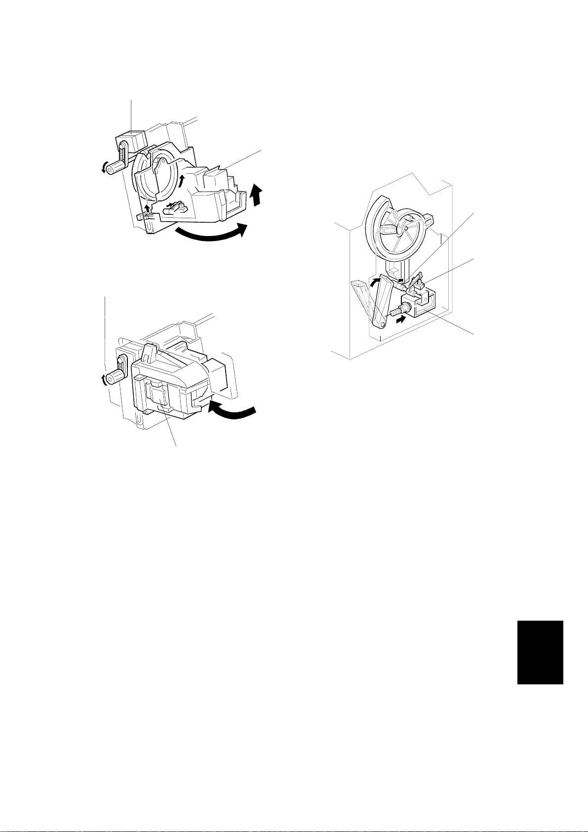
Rotation (1)
In the oblique staple position mode, the stapler rotation motor [A] rotates the
stapler units [B] 45° to counterclockwise after it moves to the stapling position.
Rotation (2)
When the s taple end cond ition arises, the stapler motor moves the stapler to the
front and the stapler rotation motor rotates the stapler unit to clockwise to remove
the staple cartridge [C]. This allows the user to add new staples.
Once the staples have been installed, and the front door closed, the stapler unit
returns to its home position. As the stapler unit is returning to the home position,
the stapler return sensor [D] is activated, the return solenoid [E] turns on and it
assists the guide roller [F] to return to its guide (this guide directs the stapler during
rotation).
B302-11
Options
Page 13

STAPLER 22 October 1999
2.5 STAPLER
[C]
[E]
[B]
[D]
[A]
B302D516.WMF
B302D521.WMF
[E]
[F]
B302D522.WMF
[G]
When the aligned copies are brought to the stapling position by the positioning
roller and jogger fences, the staple hammer motor [A] starts stapling.
During stapling, the stapler trims off the excess length [B] of the staples by lowering
the cutter [C]. This excess length depends on the number of copies in the set;
there will be very little for a stack containing 100 sheets. The staple waste drops
into the tray [D] in the stapler. When the stapler unit returns to its home position,
the tray hits the shaft [E] and the tray opens. The staple waste drops into the staple
waste hopper [F]. When the staple waste hopper is full, the actuator on its base
activates the staple waste hopper sensor [G]. An SC is displayed.
B302-12
Page 14

22 October 1999 STAPLER
[C]
[B]
B302D517.WMF
[A]
[D]
[E]
[G]
[F]
B302D518.WMF
The stapler has a staple end sensor [A], cartridge set sensor [B] and staple
hammer HP sensor [C].
When a staple end or no cartridge condition is det ected, a message is displayed
advising the operator to install a staple cartridge. If this condition is detected during
a copy job, the indication will appear, and the copy job will stop.
The staple cartridge has a clinch area [D], in which jammed staples are left.
Operators can remove the jammed staples from this area.
When the operator lifts the release lever [E], the clinch area is released from the
cartridge by pushing the holders [F]. The jammed staples can be removed.
The staple sheet can be feed manually by sliding the knob [G].
Options
B302-13
Page 15

FEED-OUT 22 October 1999
2.6 FEED-OUT
[D][G]
[A]
[B]
[E]
[C]
[H]
[F]
B302D519.WMF
B302D512.WMF
After the copies have been stapled, the stack feed-out motor [A] starts. The pawl
[B] on the stack feed-out belt [C] transports the set of stapled copies up and feeds
it to the shift tray exit roller [D]. When stapling starts, the exit guide motor [E] opens
the upper exit guide [F], which includes the upper shift tray exit roller [G], in order to
feed out the leading edge of the copy set smoothly. The exit guide motor turns on
again a certain time after stapling is complete, and the upper exit guide plate is
lowered. Then the shift tray exit roller takes over the stack feed-out.
The on-off timing of the exit guide motor is detected by the exit guide open sensor
[H].
The stack-feed-out motor turns off when the pawl actuates the stack feed-out belt
home position sensor [I].
[I]
B302-14
Page 16

22 October 1999 SHIFT TRAY UP/DOWN MOVEMENT
2.7 SHIFT TRAY UP/DOWN MOVEMENT
[A]
[K]
[D]
[E]
[J]
[G]
[H]
[F]
[B]
[I]
[C]
B302D010.WMF
The shift tray lift motor [A] controls the vertical position of the shift tray [B] through
gears and timing belts [C]. When the main switch is turned on, the tray is initialized
at the upper position. The tray is moved up until stack height sensor 1 [D] is deactuated.
In sort/stack mode, if stack height sensor 2 [E] is actuated for 2 seconds, the shift
tray lift motor lowers the shift tray for 20 ms.
In staple mode, when the pawl on the stack feed-out belt reaches the upper
position of the staple unit, the shift tray lift motor lowers the shift tray for 400 ms
and stops for 200 ms. Then, it lifts the shift tray until stack height sensor 1 is deactuated by the feeler [F]. This means the tray lowers earlier in staple mode, to
prevent the next copy suddenly exceeding the space currently available on the
tray.
For both modes, the shift tray will rise until stack height sensor 1 is de-actuated
when the user takes the stack of paper from the shift tray.
This machine has two shift tray lower limit sensors 1 [G], 2 [H]. Shift tray lower limit
sensor 1 detects the near lower limit and sensor 2 detects the lower limit. When the
actuator [I] enters sensor 1, a message will be displayed and copying will continue.
When the actuator enters sensor 2, a message will be displayed and copying will
stop.
Options
The shift tray upper limit switch [J] prevents the drive gear from being damaged if
stack height sensor 1 fails. When the shift tray pushes up the shift tray positioning
roller [K], the switch will cut the power to the shift tray lift motor.
B302-15
Page 17

SHIFT TRAY SIDE-TO-SIDE MOVEMENT 22 October 1999
2.8 SHIFT TRAY SIDE-TO-SIDE MOVEMENT
[D]
[A]
[F]
[C]
[E]
[B]
B302D520.WMF
In sort/stack mode, the shift tray [A] moves from side to side to separate the sets of
copies.
The horizontal position of the shift tray is controlled by the shift motor [B] and shift
gear disk [C]. After one set of copies is made and delivered to the shift tray, the
shift motor turns on, driving the shift gear disk and the shaft [D]. The end fence [E]
is positioned by the shaft, creating the side-to-side movement.
When the shift gear disk has rotated 180 degrees (when the shift tray is fully shifted
across), the cut-out in the shift gear disk turns on the shift tray half-turn sensor [F]
and the shift motor stops. The next set of copies is then delivered. The motor turns
on, repeating the same process and moving the tray back to the previous position.
B302-16
Page 18

22 October 1999 PUNCH UNIT DRIVE
2.9 PUNCH UNIT DRIVE
[D]
[C]
[A]
[B]
B302D001.WMF
The punch unit makes 2 or 3 holes (depending on the type of punch unit) at the
trailing edge of the paper.
The punch unit is driven by the punch motor [A]. The punch motor turns on 78 ms
after the trailing edge of the pape r passes through the entrance sensor [B], and
makes the punch holes.
The home position is detected by the punch HP sensor [C]. When the cut-out in the
punch shaft gear disk [D] enters the punch HP sensor, the punch motor stops.
The punch position is adjusted as follows:
·
Right to left: SP mode
·
Front to rear: Spacers
B302-17
Options
Page 19

PUNCH WASTE COLLECTION 22 October 1999
2.10 PUNCH WASTE COLLECTION
[D]
[B]
[C]
[A]
B302D002.WMF
The punch waste is collected in the punch waste hopper [A], which is under the
punch unit.
When the punch waste covers the hole [B] in the hopper, the punch waste hopper
sensor [C] turns on and a message will be displayed after the copy job f inishes.
The punch waste hopper sensor also works as the hopper set sensor. If the punch
waste hopper is not set, the sensor stays away from the hole in the hopper holder
[D] and a message is displayed. This messag e is the same as for the hopper ful l
condition.
B302-18
Page 20

22 October 1999 JAM CONDITIONS
2.11 JAM CONDITIONS
1. The entrance sensor does not turn on when the copier has fed paper 426 mm
after the copier exit sensor turned off.
2. The entrance sensor does not turn off when the upper transport motor has fed
paper 1.5 times the paper’s length after it turned on.
3. The upper tray exit sensor does not turn on when the upper transport motor
has fed paper 574 mm after the entrance sensor turned on.
4. The upper tray exit sensor does not turn off when the upper transport motor
has fed paper 1.5 times the paper’s length after it turned on.
5. In sort/stack mode, the shift tray exit sensor does not turn on when the upper
transport motor has fed paper 783 mm after the entrance sensor turned on.
6. In sort/stack mode, the shift tray exit sensor does not turn off when the upper
transport motor has fed paper 1.5 times the paper’s length after it turned on.
7. In staple mode, the stapler tray entrance sensor does not turn on when the
upper and lower transport motor have fed paper 835 mm after the entrance
sensor turned on.
8. In staple mode, the stapler tray entrance sensor does not turn off when the
upper transport motor has fed paper 1.5 times the paper’s length after it turned
on.
9. In staple mode, the stapler tray paper sensor does not turn off within 250
pulses of the stack feed-out motor after it started.
10. In staple mode, the shift tray exit sensor does not turn off within 1,260 ms after
the stack feed-out motor started.
B302-19
Options
Page 21

DIP SWITCHES 22 October 1999
3. SERVICE TABLES
3.1 DIP SWITCHES
DPS100
1234
0000Default
1 0 0 0 Free run: A4 sideways, staple mode
0 1 0 0 Free run: staple and tray shift
NOTE:
Do not use any other settings.
Description
3.2 TEST POINTS
No. Label Monitored Signal
TP100 (5V) +5 V
TP101 (GND) Ground
TP102 (RXD) RXD
TP103 (TXD) TXD
3.3 FUSES
No. Function
FU100 Protects 24 V.
B302-20
Page 22

22 October 1999 COVER REPLACEMENT
4. REPLACEMENT AND ADJUSTMENT
4.1 COVER REPLACEMENT
[A]
[D]
[B]
B302R502.WMF
[C]
B302R505.WMF
Front Door
1. Remove one screw and loosen the other screw of the upper hinge for the front
door [A].
2. Remove the front door [B].
Left Inner Cover
1. Remove the front door.
2. Remove the left inner cover [C] (1 screw).
Inner Cover
1. Remove the three screws and unhook the pawls.
2. Remove the inner cover [D].
B302-21
Options
Page 23

COVER REPLACEMENT 22 October 1999
[C]
[F]
[B]
[G]
[G]
B302R503.WMF
[A]
[H]
[H]
Table
1. Slide the table [A] to the right and remove it (2 screws).
Upper Tray
1. Click the release lever [B].
2. Remove the upper tray [C].
[D]
[D]
[E]
[E]
B302R504.WMFB302R504.WMF
Left Upper Cover
1. Remove the left upper cover [D].
Left Lower Cover
1. Remove the left lower cover [E].
Upper Cover
1. Remove the table.
2. Remove two stepped screws [F].
3. Remove the left upper cover.
4. Slide across the right cover [G] and remove it (2 screws).
Rear Cover
1. Remove the rear cover [H] (2 screws).
B302-22
Page 24

22 October 1999 COVER REPLACEMENT
[A]
[B]
B302R501.WMF
[C]
[D]
B302R504.WMF
Shift Tray
1. Remove the left upper cover.
2. Rotate the shift tray lift gear [A] manually to lower the shift tray [B]
3. Remove the shift tray (4 screws).
Front Shift Tray Cover
1. Remove the front shift tray cover [C] (1 screw).
Rear Shift Tray Cover
[B]
1. Remove the rear shift tray cover [D] (1 screw).
B302-23
Options
Page 25

POSITIONING ROLLER REPLACEMENT 22 October 1999
4.2 POSITIONING ROLLER REPLACEMENT
[A]
1. Open the front door.
2. Remove the snap ring [A].
3. Release the rubber belt [B].
4. Replace the positioning roller [C].
[C]
[B]
B302R506.WMF
B302-24
Page 26

22 October 1999 ALIGNMENT BRUSH ROLLER REPLACEMENT
4.3 ALIGNMENT BRUSH ROLLER REPLACEMENT
[B]
[D]
B302R507.WMF
[C]
[A]
[E]
[H]
[I]
[F]
[G]
B302R508.WMF
1. Open the front door and pull out the staple unit.
2. Remove the rear cover.
3. Remove the screw [A] and a tension spring [B] for the tension bracket [C], and
release the tension of the timing belt.
4. Remove the pulley [D] and ball bearing [E] (1 E-ring each).
5. Remove screw [F] of the inner cover [G].
6. Open the guide [H] and a part of the inner cover, and remove the alignment
brush roller assembly [I] (1 E-ring).
7. Replace the alignment brush roller (1 E-ring, 1 ball bearing).
Options
B302-25
Page 27

SENSOR REPLACEMENT 22 October 1999
4.4 SENSOR REPLACEMENT
4.4.1 STACK HEIGHT 1, 2 AND EXIT GUIDE OPEN SENSOR
[A]
[B]
[C]
[D]
[E]
[F]
B302R509.WMF
1. Remove the upper cover.
Stack Height Sensors 1 and 2
2. Remove the sensor feeler [A] (1 screw).
3. Remove the sensor bracket [B] (1 screw).
4. Replace the stack height sensor 1 [C] or 2 [D] (1 connector each).
Exit Guide Open Sensor
2. Remove the sensor bracket [E] (1 screw).
3. Replace the exit guide open sensor [F] (1 connector).
B302-26
Page 28

22 October 1999 SENSOR REPLACEMENT
4.4.2 UPPER TRAY PAPER LIMIT AND EXIT SENSOR
[D]
[B]
[C]
[A]
[E]
B302R510.WMF
1. Remove the upper cover.
Upper Tray Paper Limit Sensor
2. Remove the sensor cover [A] (2 screws).
3. Remove the sensor bracket [B] (1 screw).
4. Replace the upper tray paper limit sensor [C] (1 connector).
Upper Tray Exit Sensor
2. Remove the sensor bracket [D] (1 screw).
3. Replace the upper tray exit sensor [E] (1 connector).
Options
B302-27
Page 29

SENSOR REPLACEMENT 22 October 1999
4.4.3 SHIFT TRAY EXIT SENSOR
[C]
[B]
[A]
B302R511.WMF
1. Remove the upper cover.
2. Open the front door.
3. Remove the inner cover.
[A]
[D]
[E]
B302R512.WMF
4. Release two springs [A] of the upper exit guide [B].
5. Release the link [C] from the cam and remove the upper exit guide (1 plastic
clip, 1 connector).
6. Remove the guide stay [D] (2 screws).
7. Replace the shift tray exit sensor [E] (1 screw, 1 connector).
B302-28
Page 30

22 October 1999 SENSOR REPLACEMENT
4.4.4 ENTRANCE AND STAPLER TRAY ENTRANCE SENSORS
[B]
[A]
B302R513.WMF
Entrance Sensor
1. Remove the finisher from the copier.
2. Remove the sensor bracket [A] (1 screw).
3. Replace the entrance sensor [B] (1 screw, 1 connector).
Stapler Tray Entrance Sensor
1. Open the front door.
2. Remove the sensor bracket [C] (1 screw).
[D]
[C]
B302R514.WMF
3. Replace the stapler tray entrance sensor [D] (1 screw, 1 connector).
B302-29
Options
Page 31

SENSOR REPLACEMENT 22 October 1999
4.4.5 PRE-STACK STOPPER SENSOR
[A]
B302R515.WMF
[D]
[B]
[C]
B302R516.WMF
1. Remove the rear cover.
2. Remove two plastic clips from the guide [A].
3. Open the front door.
4. Remove the left vertical transport guide [B].
5. Remove the middle vertical transport guide [C] (1 connector).
6. Replace the pre-stack paper sensor [D] (1 connector).
B302-30
Page 32

22 October 1999 SENSOR REPLACEMENT
4.4.6 STAPLE WASTE HOPPER SENSOR
[A]
[B]
[C]
B302R517.WMF
1. Open the front door and pull out the stapler unit.
2. Remove the staple waste hopper [A] (1 plastic clip).
3. Remove the hopper holder [B] (2 E-rings).
4. Replace the staple waste hopper sensor [C] (1 connector).
B302-31
Options
Page 33

SENSOR REPLACEMENT 22 October 1999
4.4.7 STAPLER ROTATION HP AND STAPLER RETURN
SENSORS
[C]
[A]
[B]
B302R519.WMF
1. Remove the stapler unit.
2. Remove the stapler bracket [A] (4 screws, 2 springs).
Stapler Rotation HP Sensor
3. Replace the stapler rotation HP sensor [B] (1 connector).
Stapler Return Sensor
3. Replace the stapler return sensor [C] (1 connector).
B302-32
Page 34

22 October 1999 STAPLER REMOVAL
4.5 STAPLER REMOVAL
[B]
[A]
B302R518.WMF
1. Open the front door and pull out the staple tray.
2. Remove the stapler unit harness cover [A].
3. Remove the stapler [B] (1 screw, 2 connectors).
Options
B302-33
Page 35

PUNCH POSITION ADJUSTMENT 22 October 1999
4.6 PUNCH POSITION ADJUSTMENT
B302R520.WMF
Right to Left
This position is adjusted by SP modes.
Front to Rear
The optional punch units have the following 3 spacers as accessories.
1 mm thickness: 2 pcs
2 mm thickness: 1 pc
The punch position can be adjusted by up to 4 mm by combinations of the 3
spacers.
B302-34
Page 36

ELECTRICAL COMPONENT LAYOUT (FINISHER: B302)
46
45
44
43
42
41
40
39
47
B302S501.WMF
48
2
1
3
4
5
6
38
37
36
35
34
33
32
31
30
29
22
23
24
25
26
27
28
19
7
8
9
10
11
12
13
14
15
16
17
18
2021
B302S502.WMF
Symbol Index No. Description P to P
Motors
M1 7 Upper Transport A6
M2 14 Lower Transport C6
M3 37 Jogger F6
M4 23 Stack Plate G6
M5 22 Stapler G6
M6 33 Stapler Rotation I6
M7 28 Staple Hammer I6
M8 38 Stack Feed-out F6
M9 47 Exit Guide C6
M10 3 Shift Tray Exit B6
M11 40 Shift D6
M12 2 Shift Tray Lift C6
M13 9 Punch J2
Sensors
S1 10 Entrance B2
S2 39 Pre-stack E2
S3 21 Stapler Tray Entrance F2
S4 36 Jogger Fence HP F2
S5 35 Stapler Tray Paper F2
S6 24 Stack Plate HP G2
S7 32 Stapler HP G2
S8 31 Stapler Rotation HP G2
S9 30 Staple Hammer HP J2
S10 29 Cartrid ge Set J2
S11 27 Staple End J2
S12 18 Staple Waste Hopper I2
S13 34 Stack Feed-out Belt HP F2
S14 46 Exit Guide Open C2
Symbol Index No. Description P to P
S15 43 Shift Tray Exit C2
S16 45 Stack Height 1 D2
S17 44 Stack Height 2 D2
S18 1 Upper Tray Exit C2
S19 48 Upper Tray Paper Limit C2
S20 41 Shift Tray Half-turn D2
S21 19 Shift Tray Lower Limit 1 E2
S22 20 Shift Tray Lower Limit 2 E2
S23 13 Punch Waste Hopper J2
S24 8 Punch HP I2
S25 25 Stapler Return I2
Switches
SW1 17 Front Door Safety B2
SW2 42 Shift Tray Upper Limit C6
Solenoids
SOL1 4 Stapler Junction Gate D6
SOL2 5 Tray Junction Gate D6
SOL3 11 Pre-stack Junction Gate E6
SOL4 16
SOL5 15 Positioning Roller E6
SOL6 26 Stapler Return I6
PCBs
PCB1 12 Main K4
PCB2 6 Punch J3
Pre-stack Paper
Stopper
E6
Page 37

1234567
POINT TO POINT DIAGRAM (Finisher: B302)
A
Copier
B
Front Door Safety
CN500-8
-7
-6
-5
-4
-3
-2
-1
CN505-8
-7
-6
-5
SW1
Switch
CN305-3
Entrance Sensor
Upper Tray Exit
Sensor
Upper Tray Paper
C
Limit Sensor
Shift Tray Exit
Sensor
Exit Guide Open
Sensor
Stack Height 2
Sensor
D
Stack Height 1
Sensor
Shift Tray Half Turn
Sensor
Shift Tray Lower
Limit 2 Sensor
E
Shift Tray Lower
Limit 1 Sensor
Pre-stack Tray Paper
Sensor
Stapler Tray
Entrance Sensor
Stack Feed-out Belt
F
HP Sensor
Stapler Tray Paper
Sensor
Jogger Fence HP
Sensor
Stack Plate HP
Sensor
G
Stapler HP Sensor
Stapler Rotation HP
S1
CN310-3
S18
CN315-3
S19
CN320-3
S15
CN325-3
S14
CN330-3
S17
CN335-3
S16
CN340-3
S20
CN345-3
S22
CN350-3
S21
CN355-3
S2
CN360-3
S3
CN365-3
S13
CN370-3
S5
CN375-3
S4
CN380-3
S6
CN385-3
S7
CN390-3
S8
Sensor
CN395-3
Stapler Return Sensor
I
Staple Waste Hopper
S25
CN400-3
S12
Sensor
Punch HP Sensor
Punch Waste Hopper
Sensor
J
Punch Motor
S24
S23
M
13
CN510-3
-2
-1
CN515-3
-2
-1
CN520-3
-2
-1
CN525-3
-2
-1
CN530-9
-2
-1
CN530-6
-2
-1
CN530-3
-2
-1
CN535-3
-2
-1
-2
-1
-2
-1
CN540-1
-2
-1
CN545-3
-2
-1
CN550-6
-2
-1
CN550-3
-2
-1
-2
-1
-2
-1
-2
-1
-2
-1
-2
-1
CN555-3
-2
-1
Punch
(PCB2)
PCB
-2
-1
-2
-1
-2
-1
-2
-1
-8
-7
-5
-4
-2
-1
-2
-1
-2
-3
-2
-1
-5
-4
-2
-1
-2
-1
CN100-1
CN105-1
CN110-1
CN115-1
CN115-4
CN115-7
CN120-1
CN120-4
CN120-7
CN120-10
-11
-12
CN125-1
CN125-4
CN125-7
CN130-1
CN130-4
CN135-1
CN135-4
CN135-7
CN135-10
-11
-12
CN140-1
CN140-4
CN140-8
-10
CN140-11
-12
-13
CN215
-12
-1
-11
-2
-10
-3
-4
-8
-9
-10
-11
-12
[24] +24V
-2
[24] +24V
-3
[24] +24V
-4
[0] GND
-5
[0] GND
-6
[0] GND
-7
[0] GND
-8
[24] +24V
[0] GND
-2
TXD
-3
[0] GND
-4
RXD
[24] +24V
-2
[s24] +24V SW
[0] GND
-2
[t5]
-3
[5] +5V
[t5]
-5
[0] GND
-6
[5] +5V
[5] +5V
-8
[t5]
-9
[0] GND
[0] GND
-2
[t5]
-3
[5] +5V
[0] GND
-5
[t5]
-6
[5] +5V
[0] GND
-8
[s5]
-9
[5] +5V
[0] GND
[s5]
[5] +5V
[0] GND
-2
[s5]
-3
[5] +5V
[0] GND
-5
[s5]
-6
[5] +5V
[0] GND
-8
[s5]
-9
[5] +5V
[0] GND
-2
[t5]
-3
[5] +5V
[0] GND
-5
[t5]
-6
[5] +5V
[s5]
-2
[0] GND
-3
[5] +5V
[0] GND
-5
[t5]
-6
[5] +5V
[0] GND
-8
[s5]
-9
[5] +5V
[0] GND
[s5]
[5] +5V
[0] GND
-2
[s5]
-3
[5] +5V
[0] GND
-5
[s5]
-6
[5] +5V
[0] GND
-9
[s5]
[5] +5V
[0] GND
[s5]
[5] +5V
[t5] Hopper Sensor
[t5] Installed
[s5] HP Sensor
-9
Type 1
-8-5
Type 2
-7-6
[t5] ON
-6-7
[0] Direction
-5
[0/5] Clock
-4
[0] GND
-3
[5] +5V
-2
[0] GND
-1
[24] +24V SW
Main Board
(PCB1)
+24V SW [24]
+24V SW [24]
GND [0]
GND [0]
Speed [0/5]
Rotate [t5]
Clock [0/5]
Direction [5]
ON [t5]
GND [0]
+5V [5]
+24V SW [24]
+24V SW [24]
A [24 0/24]
/A [24 0/24]
B [24 0/24]
/B [24 0/24]
+[s24]
[t24]
+[s24]
-[s24]
+24V SW [24]
[t24]
+24V SW [24]
+24V SW [24]
A [24 0/24]
/A [24 0/24]
B [24 0/24]
/B [24 0/24]
[t24]
+24V SW [24]
+24V [24]
[t24]
+24V [24]
[t24]
+24V [24]
[t24]
+24V [24]
[t24]
+24V SW [24]
[t24]
+24V SW [24]
+24V SW [24]
A [24 0/24]
/A [24 0/24]
B [24 0/24]
/B [24 0/24]
+24V SW [24]
+24V SW [24]
A [24 0/24]
/A [24 0/24]
B [24 0/24]
/B [24 0/24]
+24V SW [24]
+24V SW [24]
A [24 0/24]
/A [24 0/24]
B [24 0/24]
/B [24 0/24]
+24V SW [24]
+24V SW [24]
A [24 0/24]
/A [24 0/24]
B [24 0/24]
/B [24 0/24]
+24V SW [24]
+24V SW [24]
A [24 0/24]
/A [24 0/24]
B [24 0/24]
/B [24 0/24]
+24V SW [24]
[t24]
+[s24]
-[s24]
GND [0]
Ready [t5]
Cartridge Set [t5]
Staple End [t5]
GND [0]
Hammer HP [t5]
+5V [5]
CN145-1
-10
-11
-12
CN150-1
CN160-3
CN150-9
-10
CN150-12
-13
CN155-1
CN160-1
CN165-1
CN165-3
CN170-1
CN175-1
CN180-1
CN190-1
CN190-9
-10
-12
-13
-14
-15
CN195-1
CN195-9
-10
-12
-13
-14
-15
CN200-1
CN200-9
-10
CN205-1
CN210-1
-2
-3
-4
-5
-6
-8
-9
-2
-4
-5
-6
-7
-5
-2
-4
-5
-6
-7
-2
-2
-4
-2
-2
-2
-2
-4
-5
-6
-7
-2
-4
-5
-6
-7
-2
-4
-5
-6
-7
-2
-2
-3
-4
-5
-6
-7
CN560-3
CN560-5
-1
-4
CN405-12
-11
-10
CN410-7
CN415-2
CN420-2
CN425-2
CN430-2
CN435-2
CN440-7
CN445-7
CN450-7
CN455-7
CN460-7
CN465-2
-9
-8
-7
-5
-4
-3
-2
-1
-6
-4
-3
-2
-1
-1
-1
-7
-6
-4
-3
-2
-1
-1
-1
-1
M1
M
10
M
12
M9
M2
M
11
SOL
2
SOL
1
SOL
3
SOL
4
SOL
5
-6
-4
-3
-2
-1
-6
-4
-3
-2
-1
-6
-4
-3
-2
-1
-6
-4
-3
-2
-1
-6
-4
-3
-2
-1
-1
M3
M8
M4
M5
M6
SOL
6
M7
S10
S11
S9
SYMBOL TABLE
DC Line
Upper Transport
Shift Tray Exit Motor
SW2
Shift Tray Upper
Limit Switch
Shift Tray Lift Motor
Exit Guide Motor
Lower Transport
Shift Motor
Tray Junction Gate
Stapler Junction
Gate Solenoid
Pre-stack Junction
Gate Solenoid
Pre-stack Paper
Stopper Soleniod
Positioning Roller
Jogger Motor
Stack Feed-out
Stack Plate Motor
Stapler Motor
Stapler Rotation
Stapler Return
Motor
Motor
Solenoid
Solenoid
Motor
Motor
Solenoid
Stapler
A
B
C
D
E
F
G
I
J
Pulse Signal
Signal Direction
s
Active High
t
[]
Active Low
Voltage
KK
1234567
 Loading...