

Page 1

FINISHER
Page 2

Finisher
31 January 1996 OVERALL MACHINE INFORMATION
1. OVERALL MACHINE INFORMATION
1.1 SPECIFICATION
Paper Size: Maximum: 11" x 17"/A3
Minimum: 5
1/2" x 81/2"/A5 sideways
Paper Weight: Standard copying/Stack mode
14 ~ 43 lb/52 ~ 163 g/m
Staple mode
17 ~ 21 lb/64 ~ 80 g/m
2
Paper Capacity: Standard copying/Stack mode
2,000 sheets:
8
1/2" x 11"/A4 or smaller size (20 lb/80 g/m
1,000 sheets:
8
1/2" x 14"/B4 or larger size (20 lb/80 g/m
Staple mode
See the following table:
Size
Number
of Originals
2 ~ 10 sheets 100 sets 100 sets 100 sets
11 ~ 20 sheets 100 sets 50 sets 50 sets
21 ~ 30 sheets 67 sets 34 sets 34 sets
31 ~ 40 sheets 50 sets 25 sets -41 ~ 50 sheets 40 sets 20 sets --
1/2" x 11"/A4
8
or smaller size
1/2" x 11"/B4 11" x 17"/A3
8
2
2
)
2
)
Stapler Capacity: 81/2" x 11"/A4 or smaller size (20 lb/80 g/m2):
from 2 to 50 sheets
8
1/2" x 14"/B4 (20 lb/80 g/m
2
):
from 2 to 50 sheets
11" x 17"/A3 (20 lb/80 g/m
2
):
from 2 to 30 sheets
Staple Replenishment: Cartridge exchange (5,000 pieces/cartridge)
Power Source: DC 24 V (from copier)
Power Consumption: 60 VA (average)
1
Page 3

OVERALL MACHINE INFORMATION 31 January 1996
Stapling Position:
a
(1 staple)
(2 staples)
b
b
b
a a
A593V500.wmf
a = 0.2" ± 0.08" (5 ± 2 mm)
b = 0.2"
± 0.1" (5 ± 2.5 mm)
a = 0.2"
b = 0.2"
± 0.08" (5 ± 2 mm)
± 0.1" (5 ± 2.5 mm)
a = 0.2"
b = 5.20"
(8
b = 10.5"
(8
± 0.08" (5 ± 2 mm)
± 0.08" (132 ± 2 mm)
1/2" x 11"/A4 or smaller size)
± 0.08" (265 ± 2 mm)
1/2" x 14"/B4 or larger size)
Dimensions: 24.4" x 27.5" x 36.4"
(620 mm x 699 mm x 925 mm)
Weight: 110 lb/50 kg
2
Page 4

Finisher
31 January 1996 OVERALL MACHINE INFORMATION
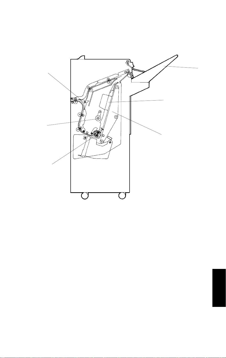
1.2 MECHANICAL COMPONENT LAYOUT
13
12
11
10
1
2
3
4
5
9
8
1. Stack Height Sensor Feeler
2. Shift Tray
3. Shift Tray Positioning Roller
4. Jogger Unit
5. Positioning Roller
6. Stack Feed-out Belt
7. Stapler Unit
6
7
A593V501.img
8. Alignment Brush Roller
9. Lower Transport Rollers
10. Junction Gate
11. Entrance Rollers
12. Upper Transport Rollers
13. Exit Rollers
3
Page 5

OVERALL MACHINE INFORMATION 31 January 1996
1.3 ELECTRICAL COMPONENT DESCRIPTION
Refer to the electrical component layout on the reverse side of the Point to
Point (water proof paper) index numbers.
Name Function Index No.
Motors
Transport Drive Drives transport rollers. 12
Shift Tray Lift Moves the shift tray up or down. 4
Exit Drive Drives the exit and shift tray positioning rollers. 5
Exit Unit Lift Lifts the exit roller unit. 1
Stack Feed-out Drives the stack feed-out belt. 8
Jogger Moves the jogger fences. 11
Stapler Drive Moves the stapler unit. 10
Shift Moves the shift tray side to side. 21
Staple Drives the staple hammer. 18
Sensors
Entrance Detects copy paper entering into the finisher. 3
Jogger Unit Entrance Detects copy paper entering into the jogger unit. 6
Jogger Unit Paper Detects copy paper in the jogger unit. 17
Stack Feed-out Belt HP Detects the home position of the stack feed-out belt. 16
Jogger HP Detects the jogger home position. 23
Exit Detects misfeeds in exit area. 25
Stack Height 1 Detects copy paper stack height in staple mode. 26
Stack Height 2 Detects copy paper stack height in sort/stack mode. 28
Shift Tray Lower Limit Detects the lower limit of the shift tray position. 14
Stapler Hammer HP Detects the staple hammer home position. 19
Exit Unit HP Detects the exit roller upper unit home position. 29
Exit Unit Half Turn Detects the exit roller upper unit position. 27
Shift Tray Half Turn Detects shift tray side to side position. 20
Stapler Unit HP Detects the stapler unit home position. 22
Front Door Safety
(Switch)
Shift Tray Upper Limit
(Switch)
Staple End Detects staple end conditions 30
Cartridge Set Detects if the staple cartridge is installed or not. 31
Cuts dc power when the front door is opened.
Detects the upper limit of the shift tray position.
24
2
Solenoids
Positioning Roller Lowers the positioning roller in the jogger unit. 9
Junction Gate Drives the junction gate. 7
4
Page 6

Finisher
31 January 1996 OVERALL MACHINE INFORMATION
Name Function Index No.
PCBs
Transport Drive Motor
Control
Main Control Controls overall finisher operation. 15
Controls the transport drive motor operation.
13
5
Page 7

OVERALL MACHINE INFORMATION 31 January 1996
1.4 DRIVE LAYOUT
1
10
9
2
3
4
5
6
8 7
A593V502.img
11
12
16
1. Shift Tray Lift Motor
2. Exit Drive Motor
3. Upper Transport Drive Belt
4. Lower Transport Drive Belt
5. Transport Drive Belt
6. Transport Drive Motor
7. Shift Tray Lift Belt
8. Shift Motor
13
14
15
A593V503.img
9. Shift Cam
10. Exit Roller
11. Stack Feed-out Motor
12. Jogger Drive Belt
13. Jogger Motor
14. Stapler Drive Motor
15. Stack Feed-out Belt
16. Stapler Drive Belt
6
Page 8
Finisher
31 January 1996 OVERALL MACHINE INFORMATION
1.5 BASIC OPERATION
[D]
[A]
[E]
[B]
[F]
[C]
A593V501.img
After the copy is completed, the paper is directed to the finisher. If the
sort/stack mode is selected, the junction gate [A] directs the paper upwards
to transport it to the shift tray [B]. In these modes, the shift tray is shifted side
to side to stagger and separate sets of copies. The amount of shift is
approximately 30 mm.
When the staple mode is selected, the junction gate directs the paper below
to transport the paper to the jogger unit [C]. Each time a copy is delivered to
the jogger unit, the positioning roller [D], the alignment brush roller [E], and
the jogger fences [F] square the stack of copies. After the final copy of the set
is squared, the set is stapled, and then delivered to the shift tray.
7
Page 9
SECTIONAL DESCRIPTION 31 January 1996
2. SECTIONAL DESCRIPTION
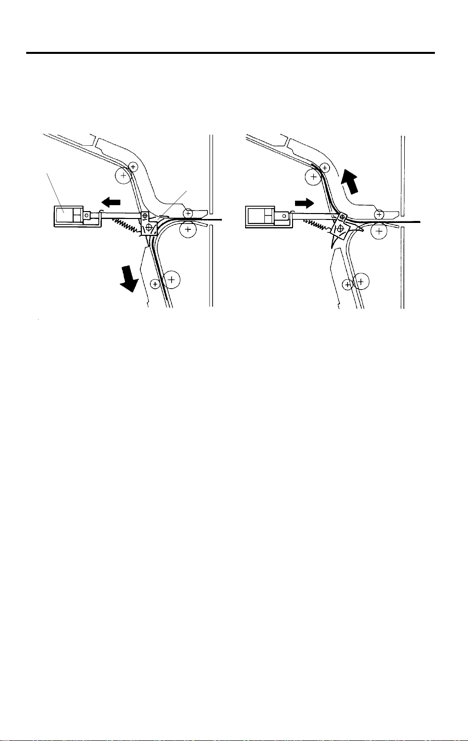
2.1 PAPER DELIVERY SWITCHING
[B]
[C] [D]
[A]
(1) Staple Mode (2) Sort/Stack Mode
A593D500.img
Depending on the selected finishing mode, the copies are directed up or
down by the junction gate [A]. A two-way solenoid is used to control the
junction gate.
(1) When the exit sensor of the copier is activated while in staple mode, the
solenoid [B] pulls the plunger in the arrow [C] direction. The junction gate
directs the copies down to transport them to the jogger unit.
(2) When the exit sensor of the copier is activated while in the sort/stack
mode, the solenoid pushes the plunger in the arrow [D] direction.
The junction gate directs the copies up to deliver them to the shift tray.
The junction gate keeps its position until a different finishing mode is selected.
8
Page 10
Finisher
31 January 1996 SECTIONAL DESCRIPTION
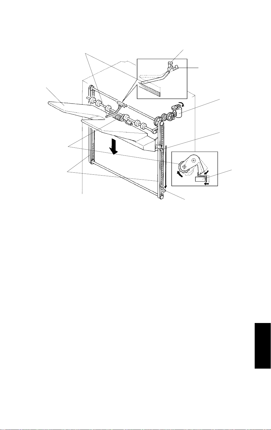
2.2 SHIFT TRAY UP/DOWN MECHANISM
[D]
[E]
[F]
[A]
[B]
[H]
[J]
[C]
[I]
[G]
A593D501.img
The vertical position of the shift tray [A] is controlled by the shift tray lift motor
(dc motor) [B] through the gears and the timing belts [C]. When the main
switch is turned on, the tray position is initialized to the upper position. The
tray’s upper most position is detected when the shift tray pushes up the
actuator [D] to deactuate the stack height sensor 1 [E].
While copying, the actuator [D] is gradually raised as the copy stack grows. In
the sort/stack mode, when the stack height sensor 2 [F] remains actuated for
4 seconds, the shift tray lift motor [B] rotates, lowering the tray unit for 50 ms.
In staple mode, when the stack height sensor 1 remains deactuated for 4
seconds, the motor rotates lowering the tray until the sensor [E] is actuated.
When the tray reaches its lower limit position, the lower limit sensor [G] is
actuated by the actuator [H], and copy operation stops.
After the copy process is finished and the machine stops, the tray is raised to
its upper most position 4 seconds after the copies are removed.
A mechanical safety switch [I] is installed to prevent the drive gears from
being damaged if the sensor does not work. When the shift tray pushes up
the shift tray positioning roller [J], the shift tray lift motor stops.
9
Page 11

SECTIONAL DESCRIPTION 31 January 1996
2.3 SHIFT TRAY SIDE TO SIDE SHIFT MECHANISM
[E]
[D]
[A]
[C]
[B]
[F]
[G]
[H]
A593D502.img
In the sort/stack mode, the shift tray [A] moves side to side to stagger and
separate sets of copies.
The horizontal position of the shift tray is controlled by the shift motor (dc
motor) [B] and the shift cam (helical cam) [C]. After one set of the original is
copied and delivered to the shift tray, the shift motor [B] starts rotating, driving
the shift cam through the timing belt. The pin [D] fixed to the shift tray base
plate [E] is positioned in the groove on the shift cam, creating the side to side
movement required to stagger copies.
When the shift cam rotates 180 degrees (The tray is fully shifted.), the plate
[F] on the shift cam pushes the actuator [G] of the shift tray half turn sensor
[H] and the shift motor stops. The next set of copies is then delivered. The
motor rotates repeating the same process and moving the tray back to the
previous position.
10
Page 12
Finisher
31 January 1996 SECTIONAL DESCRIPTION
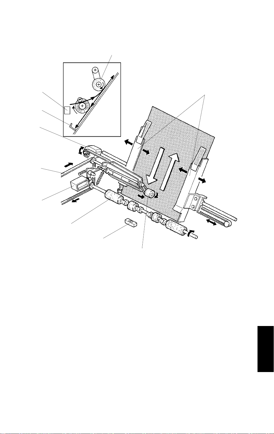
2.4 STAPLE UNIT PAPER POSITIONING
[F]
[C]
[B]
[E]
[A]
[H]
[G]
[D]
[F]
[C]
A593D503.img
In the staple mode, copies are vertically and horizontally aligned in the jogger
unit before being stapled.
For horizontal paper alignment, the jogger motor [A] moves both the front and
the rear jogger fences [B] to align the copies.
For vertical paper alignment, the positioning roller [C] and the alignment
brush roller [D] push the copy against the stack stopper [E].
After the trailing edge of the copy passes the jogger unit entrance sensor [F],
the positioning roller solenoid [G] is energized for 280 ms pushing the
positioning roller into contact with the paper. The positioning roller rotates to
push the paper back and align the trailing edge of the paper against the stack
stopper. Both the positioning roller and the alignment brush roller are driven
by the transport drive motor through the timing belt [H].
11
Page 13

SECTIONAL DESCRIPTION 31 January 1996
2.5 JOGGER MOVEMENT
8 mm
3 mm
[A] [B]
(2)(1) (3)
A593D504.wmf
When the Start key is pressed, the copier sends the paper size information to
the finisher. In accordance with that data, the jogger motor (stepper motor)
starts rotating to position the front and rear jogger fences [A] 8 mm away from
the selected paper’s edges. (1)
After the trailing edge of the copy passes the jogger unit entrance sensor,
each jogger fence moves inward 5 mm. They stop 3 mm away from the paper
edges. (2)
Just after the positioning roller pushes the copy back, each jogger fence
moves inward 3 mm more so that the leaf spring [B] on the rear jogger fence
pushes the copy side edge slightly.
After a copy is stacked in the jogger tray, the jogger fences move back 8 mm
from the copy edge for the next copy.
12
Page 14

Finisher
31 January 1996 SECTIONAL DESCRIPTION
2.6 STAPLER
[G]
[H]
[E]
[B]
[A]
[D]
[C]
[F]
A593D505.wmf
[J]
A593D506.wmf
The staple hammer [A] is driven by the staple motor [B] via gears [C], two
eccentric cams [D], and two links [E].
When the aligned copies are brought to the staple position by the positioning
roller, alignment brush roller and jogger fences, the stapler motor starts
rotating. When the cams complete one rotation, the stapler home position
sensor [F] turns on, detecting the end of the staple operation. The stapler
motor then stops.
There are two sensors in the staple unit. One is the staple end sensor [G] to
detect staple end conditions. The other is the cartridge set sensor [H] to
detect when the staple cartridge is not installed.
When a staple end or no staple cartridge condition is detected, a message is
displayed advising the operator to set the staple cartridge.
The staple cartridge has a clinch area [J], in which the jammed staples are
left. Operators can remove the jammed staples from the cartridge.
13
Page 15

SECTIONAL DESCRIPTION 31 January 1996
2.7 STAPLER UNIT SIDE TO SIDE MOVEMENT
[A]
A593D507.img
[C]
[B]
Customers can select one of the following three different staple modes:
Staple 1: Top left
Staple 2: Bottom left
Staple 3: Top/Bottom left
The stapler drive motor [A] (stepper motor) moves the stapler unit [B] from
side to side. When the Start key is pressed, the stapler moves from its home
position to the staple position.
If the staple mode 3 is selected, the stapler unit moves to the front staple
position first, then moves to the rear staple position. However, for the next
copy set, it staples in the reverse order; that is, at the rear side first and then
at the the front.
After the job is completed, the stapler unit moves back to its home position.
(The stapler unit home position sensor [C] is actuated.)
The staple position can be changed using SP mode.
14
Page 16

Finisher
31 January 1996 SECTIONAL DESCRIPTION
2.8 FEED-OUT TO SHIFT TRAY
[B]
[A]
[C]
[B]
[D]
A593D508.img
After being stapled, the stack feed out motor [A] starts rotating. The pawl [B]
on the lift belt [C] transports the set of stapled copies up, and feeds it to the
shift tray. Approximately 0.6 second after the stack feed out motor starts, the
motor stops for 400 ms. At this moment, the exit rollers catch the stapled
copies to feed them out to the shift tray. Then the motor rotates again until
the pawl actuates its home position sensor [D].
15
Page 17

SECTIONAL DESCRIPTION 31 January 1996
[A]
[C]
[B]
[C]
[E]
[D]
[D]
A593D509.img
In staple mode, when stapling is completed, the exit unit lift motor [A] starts
rotating to open the exit unit [B]. This is to prevent paper jams when a thick
paper stack is exiting. The exit unit lift motor stops when the exit unit half turn
sensor [C] is actuated. While the paper stack is exiting, the exit unit lift motor
starts rotation again to close the exit unit. The upper and lower exit rollers [D]
catch the stack of copies to feed them out. The exit unit lift motor stops when
the exit guide home position sensor [E] is actuated.
The exit unit lift motor does not work in sort/stack mode.
The exit drive motor starts rotating to drive the exit rollers [D] when the first
copy activates the entrance sensor. The exit drive motor speed is reduced
just before each copy paper is completely fed out. This is to ensure an even
copy stack.
16
Page 18

Finisher
31 January 1996 INSTALLATION
3. INSTALLATION
3.1 ACCESSORY CHECK
Check the quantity and condition of the accessories in the box according to
the following list.
1. Installation Procedure...................................... 1
2. Relay Guide..................................................... 1
3. Shift Tray ......................................................... 1
4. Staple Cartridge............................................... 1
5. Panhead Screw 4 x 8 ......................................10
6. Ground Screw.................................................. 1
17
Page 19

INSTALLATION 31 January 1996
3.2 INSTALLATION PROCEDURE
CAUTION
Unplug the copier power cord before starting the following procedure.
[B]
[E]
[A]
A593I500.img
[C]
A593I501.img
[F]
A593I502.wmf
1. Remove the strips of filament tape [A] on the finisher and remove the
styrofoam blocks [B]. Remove the fixing screw [C].
[D]
2. Open the finisher front door and pull out the transport unit [D]. Then,
remove the strips of filament tape [E].
3. Push the transport unit in its original position and close the front door.
18
Page 20

Finisher
31 January 1996 INSTALLATION
[G]
[A]
[B]
[E]
[D][C]
[F]
A593I503.img
A593I504.img
[H]
[I]
[J]
A593I505.img
4. Remove the copier right cover [A] (2 screws) and plastic cap [B]. Pass the
4P connector [C], fiber cable [D], and ground wire [E] of the interface
harness through the lower hole [F] of the right cover. Then, reinstall the
right cover.
NOTE: Since the 2P connector is not used for this finisher installation,
keep it in the copier.
5. Install the relay guide [G] (2 screws).
6. Bring the finisher near the main copier and confirm that the height of the
relay guide exit plates [H] are aligned between the finisher entrance
plates [I].
NOTE: If not, adjust the height of the relay guide exit plates (loosen the 2
screws [J]).
19
Page 21

INSTALLATION 31 January 1996
[C]
[B]
[A]
A593I506.img
[E]
A593I507.img
7. Connect the 4P connector [A], fiber cable [B], and fix the ground wire [C]
(1 screw with a star washer).
NOTE: 220/230/240 V market only
The finisher unit meets EN 60 950, Class
ΙΙΙ safety standards,
which do not require an earth connection. However, it should be
grounded to ensure proper operation.
[D]
8. Remove the finisher right cover [D] (2 screws).
9. Connect the finisher to the main copier (4 screws) and reinstall the
finisher right cover.
10. Install the finisher shift tray [E] (4 screws).
11. Plug in the power cord and turn on the copier main switch.
12. Test the operation of the finisher.
NOTE: The stapler will not be stapling for the first 10 or so copies until
the first staple comes to the proper position from the cartridge.
20
Page 22

Finisher
31 January 1996 SERVICE TABLES
4. SERVICE TABLES
4.1 TEST POINT TABLE (Main Board)
Number Function
TP1 24 V
TP2 GND
TP3 5 V
4.2 FUSE TABLE
Number Rated Current Location
Fuse 1 5A Main PCB
Fuse 1 8A Transport Drive Motor Control PCB
4.3 DIP SW TABLE
4.3.1 Motor Test Mode
DIP100 DIP101
1 2 3 4 1 2 3 4
0 0 0 1 1 0 1 1 Transport Drive Motor
0 0 1 0 1 0 1 1 Exit Drive Motor
0 1 0 0 1 0 1 1 Stack Feed-out Motor
1 0 0 0 1 0 1 1 Shift Tray Lift Motor
Motor
0: OFF 1: ON
Factory
Setting
0 0 0 0 0 0 0 0
DIP100 DIP101
After setting the DIP SW101, turn on one of the DIP SW100 to start the
appropriate motor, turn off the DIP SW 100 to stop the motor.
DIP SW100-4 ON: The finisher shift tray is raised during a continuous copy
run if the copies have been removed from the tray.
21
Page 23

SERVICE TABLES 31 January 1996
4.4 Free Run Test Mode
DIP101
1 2 3 4
0 0 1 1 Motor Free Run
0 1 1 1 Staple Free Run
1 1 1 1 Shift Free Run
Function
0: OFF 1: ON
Free run test mode starts when the SW100 on the main board is pressed,
and stops when the SW101 is pressed.
Operation:
1. Motor Free Run
The motors of the finisher are energized in the following order:
Transport drive motor Exit motor Stack feed out motor
Shift motor Shift tray lift motor Exit unit lift motor
The PCB checks the speed of the transport drive, exit and stack feed
motors, and mechanical lock of the other motors.
2. Staple Free Run
The finisher works as if 5 sets of 5 LT papers are being stapled and
delivered. The machine is then initialized and repeats the same operation.
3. Shift Free Run
The finisher works as if 10 sets of 5 LT papers are being sorted. The shift
tray is lowered for each of the 2 sets and then returns to its home position
to repeat the same operation.
22
Page 24

Finisher
31 January 1996 SERVICE TABLES
4.5 PM TABLE
NOTE: Amounts mentioned in the PM interval are copy numbers.
C: Clean R: Replace L: Lubricate
ITEM EM 1.5M NOTE
Rollers C Alcohol
Antistatic Brush C Dry cloth
Brush Rollers R 2 large and 2 small rollers
Bushings L Launa oil; if it makes noise
Sensors C Blower brush
Stapler I Replace after 200K staples.
4.6 LUBRICATION POINTS
At an EM call or when the parts are getting dry, lubricate the following parts
using a suitable lubricant.
4.6.1 Shift Tray Positioning Roller Arm
Lubricant: Launa--40 oil or equivalent
A593M500.img
23
Page 25

SERVICE TABLES 31 January 1996
4.6.2 Jogger/Staple Unit Shafts
Lubricant: Launa--40 oil or equivalent
4.6.3 Shift Tray Drive Gears
Lubricant: Grease G--501
A593M501.img
24
A593M502.img
Page 26

Finisher
31 January 1996 REPLACEMENT AND ADJUSTMENT
5. REPLACEMENT AND ADJUSTMENT
5.1 EXTERIOR REMOVAL
[A]
[C]
[B]
[D]
[E]
[F]
[G]
[H]
[I]
A593R500.img
1. Open the front door [A] and remove the upper cover [B] (2 screws).
2. Remove the upper door bracket [C] (2 screws) and remove the front door
[A].
3. Remove the front shift cover [D] (2 screws).
4. Remove the rear cover [E] (3 screws).
5. Remove the right upper cover [F] (2 screws).
6. Remove the shift tray [G] (4 screws).
7. Remove the front and rear tray cover [H] (1 screw each).
8. Remove the right cover [I] (2 screws).
25
Page 27

REPLACEMENT AND ADJUSTMENT 31 January 1996
5.2 STAPLE UNIT REMOVAL
[B]
[A]
A593R520.wmf
[C]
[E]
[D]
A593R521.wmf
1. While holding the stack stopper [A] at the front side, remove the staple
unit cover [B] (2 screws).
2. While holding the stack stopper at the front side, remove the staple unit
[C] (2 screws [D] and 1 connector [E]).
[D]
26
Page 28

Finisher
31 January 1996 REPLACEMENT AND ADJUSTMENT
5.3 SHIFT TRAY UNIT REMOVAL
[A]
[B]
A593R501.img
[G]
[H] [F] [E] [D] [C]
[G][I]
[H]
A593R502.img
1. Remove the front door, upper cover, front shift cover, rear cover, right
upper cover, and the right cover.
[H]
2. Remove the shift tray lift motor assembly [A] (4 screws).
3. Remove the harness holder plate [B] (3 screws).
4. Remove the screw [C] spring [D], bushing [E] and pulley [F].
5. Disconnect the 7 connectors [G].
6. Remove the 6 screws [H].
7. Lift the shift tray unit [I] off from the hooks [J] and remove.
27
Page 29

REPLACEMENT AND ADJUSTMENT 31 January 1996
5.4 JOGGER UNIT REMOVAL
[C]
[B]
1. Open the front door.
2. Slide out the jogger unit [A].
3. Remove the four screws [B] fixing the unit to the slide rails [C].
4. Lift the jogger unit off from the slide rails.
[A]
A593R503.img
28
Page 30

Finisher
31 January 1996 REPLACEMENT AND ADJUSTMENT
5.5 ALIGNMENT BRUSH ROLLER REPLACEMENT
[B]
[A]
[C]
[A]
[E]
[F]
[C]
[D]
[H]
A593R504.img
[J]
[I]
[G]
A593R505.img
1. Remove the rear cover.
2. Mark the position of the tension bracket [A] and loosen the screw [B].
3. Remove the 2 E-rings [C], slide out the pulley [D] and bushing [E], and
remove the alignment brush roller assembly [F].
4. Remove the screws [G], E-rings [H], pins [I], and remove the brush rollers
[J].
NOTE: 1. When reassembling, put the bracket [A] back to the marked
position.
2. Do not lose the pins [I].
29
Page 31

REPLACEMENT AND ADJUSTMENT 31 January 1996
5.6 JOGGER DRIVE BELT REPLACEMENT
[B]
[E]
[G]
[D]
[A]
[C]
[F]
A593R506.img
1. Open the front door and slide out the staple unit [A].
2. Remove the front and rear jogger fences [B] (2 screws each).
3. Remove the 2 screws [C] fixing the jogger fence sliders [D] to the belt
clampers [E].
4. Mark the position of the tension bracket [F] and remove it (1 screw).
5. Remove the jogger drive belt [G] with the belt clampers [C].
NOTE: When reassembling, put the bracket [F] back to the marked
position.
30
Page 32

Finisher
31 January 1996 REPLACEMENT AND ADJUSTMENT
5.7 EXIT ROLLER REPLACEMENT
[B]
[C]
[D]
[E]
[F]
[G]
[A]
[E]
[H]
[J]
[G]
[K]
[I]
A593R507.img
1. Remove the upper cover, front door, front shift cover, rear cover, and right
upper cover.
2. Remove the screw [A], spring [B], bushing [C], and pulley [D].
3. Remove the 4 screws [E] fixing the lower exit guide plate [F].
4. Remove the 2 E-rings [G] and remove the exit roller assembly [H].
5. Remove the E-rings [I], pins [J] and replace the exit rollers [K].
NOTE: Do not lose the pins [J].
31
Page 33

REPLACEMENT AND ADJUSTMENT 31 January 1996
5.8 SHIFT TRAY POSITIONING ROLLER REPLACEMENT
[C]
[A]
[D]
[B]
A593R508.img
1. Raise the stack height sensor actuator [A] and hold it until the shift tray
automatically lowers.
2. Turn off the main switch before the shift tray returns to its home position.
NOTE: If the machine is in a condition that does not allow the shift tray to
be lowered electrically, then remove the shift tray [B].
3. Remove the 2 E-rings [C] and replace the reverse roller [D].
32
Page 34

Finisher
31 January 1996 REPLACEMENT AND ADJUSTMENT
5.9 SENSOR REPLACEMENT
[F]
[I]
[H]
[G]
[E]
[B]
[C]
[D]
[A]
A593R509.img
Stack Height Sensors
1. Remove the upper cover.
2. Remove the stack height sensor actuator [A] (1 screw).
3. Remove the bracket [B] (1 screw).
4. Replace the stack height sensor 1 [C] and the stack height sensor 2 [D].
NOTE: When reinstalling the bracket [B], align the edge of the bracket
with the stay [E].
Exit Unit Home Position Sensor/Exit Unit Half Turn Sensor
1. Remove the upper cover.
2. Remove the exit unit lift motor [F] (2 screws).
3. Replace the exit unit half turn sensor [G].
4. Remove the bracket [H] (1 screw) and replace the exit unit home position
sensor [I].
33
Page 35

REPLACEMENT AND ADJUSTMENT 31 January 1996
[B]
[C]
[A]
Jogger Unit Entrance Sensor
1. Remove the jogger entrance guide [A] (1 screw).
2. Remove the sensor bracket [B] (2 screws).
3. Replace the jogger unit entrance sensor [C] (1 screw).
A593R510.img
34
Page 36

Finisher
31 January 1996 REPLACEMENT AND ADJUSTMENT
[C]
[B]
[F]
[A]
A593R511.img
[E]
[D]
[G]
A593R512.img
Shift Tray Half Turn Sensor
1. Remove the rear cover.
2. Remove the shift motor bracket [A] (3 screws).
3. Remove the sensor bracket [B] (1 screw) and replace the shift tray half
turn sensor [C].
Jogger Unit Paper Sensor
1. Open the front cover and slide out the staple unit [D].
2. Remove the 2 screws [E] fixing the bracket [F].
3. Slightly pull out the bracket in the direction shown and remove the jogger
unit paper sensor [G] (1 screw).
35
Page 37

REPLACEMENT AND ADJUSTMENT 31 January 1996
5.10 BELT TENSION ADJUSTMENT
[H]
[C]
[D]
[B]
[E]
[F]
[A]
A593R513.img
1. Remove the rear cover and adjust the belt [A]
tension with tightener [a].
Remove the upper cover, the front door, and
the front shift cover. Adjust the belt [B] with
tightener [b].
[G]
A593R514.img
[A, B]
Standard: 6 mm deflection at 50
± 20 g
pressure.
2. Remove the upper cover and the rear cover.
Loosen the two screws [c] and adjust the belt
[C] tension by changing the motor position.
Standard: 2 mm deflection at 40
± 20 g
pressure.
36
[a, b]
A593R515.wmf
[C]
[c]
A593R516.wmf
Page 38

Finisher
31 January 1996 REPLACEMENT AND ADJUSTMENT
3. Remove the rear cover and adjust
the belt [D] [E] [F] tension with tightener [d]
[e] [f].
<Standard>
[D]: 6 mm deflection at 60
[E]: 6 mm deflection at 170
[F]: 6 mm deflection at 60
± 20 g pressure
± 30 g pressure
± 20 g pressure
[E]
[D]
[d]
[f]
[e]
[F]
A593R517.img
4. Open the front door and slide onto the
jogger unit. Adjust the belt [G] tension with
tightener [g].
Standard: 10 mm deflection at 65
± 20 g
pressure
5. Remove the rear cover. Loosen the
2 screws [h] and [i].
Retighten the screw [h] and then
retighten [i]. The belt [H] tension is
automatically adjusted due to spring
tension.
[G]
[g]
A593R518.wmf
[h]
[i]
[H]
37
A593R519.img
 Loading...