

Page 1

TWO-TRAY FINISHER
(Machine Code: G565)
Page 2
23 February, 2001 COVERS
1. REPLACEMENT AND ADJUSTMENT
1.1 COVERS
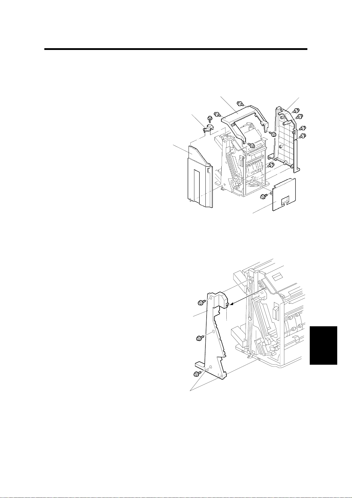
1.1.1 EXTERNAL COVERS
1. Top cover [A] (! x 4)
NOTE: If the shift tray below is
blocking the screw hole,
remove the shift tray.
[A]
[B]
[D]
2. Bracket [B] (! x 1)
3. Front door [C]
4. Rear cover [D] (! x 4)
5. Right cover [E] (! x 2)
1.1.2 INNER COVER
1. Front cover (☛ 1.1.1 EXTERNAL
COVERS)
2. Inner cover [A] (! x 3, tabs [B] x 3)
[C]
[E]
G565R151.WMF
[B]
G565-1
[A]
[B]
Peripherals
G565R102.WMF
Page 3
POSITIONING ROLLER 23 February, 2001
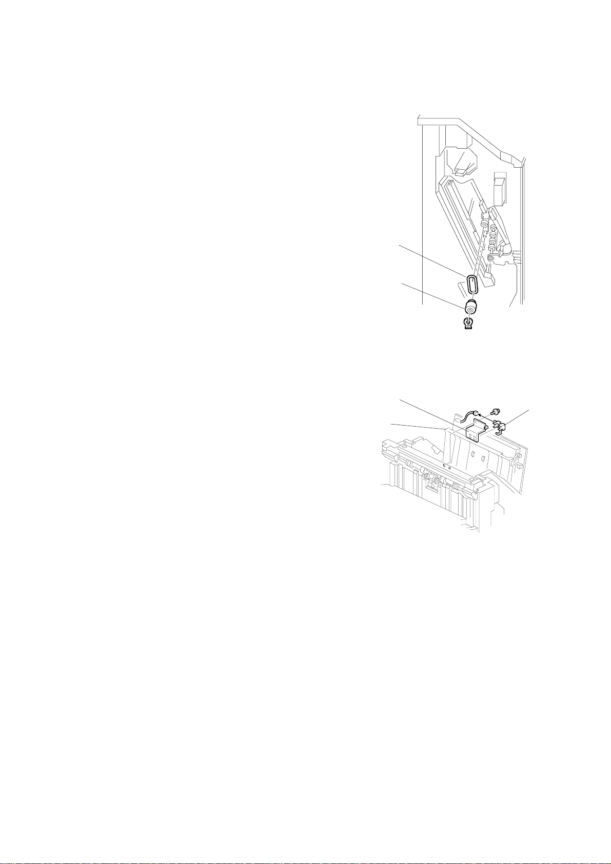
1.2 POSITIONING ROLLER
1. Open the front door.
2. Positioning roller [A] (" x 1)
3. Belt [B]
[B]
[A]
G565R103.WMF
1.3 TRAY 1 EXIT SENSOR
1. Top cover (☛ 1.1.1 EXTERNAL COVERS)
2. Open transport door [A]
3. Bracket [B] (! x 1, (# x 1)
4. Tray 1 exit sensor [C]
[B]
[C]
[A]
G565R104.WMF
G565-2
Page 4
23 February, 2001 ENTRANCE SENSOR/STAPLER TRAY ENTRANCE SENSOR
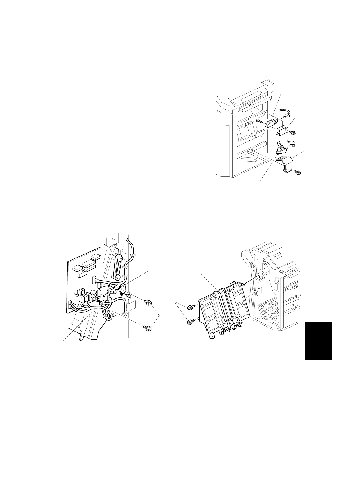
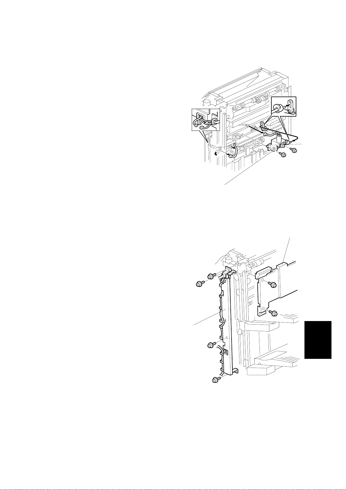
1.4 ENTRANCE SENSOR/STAPLER TRAY ENTRANCE
SENSOR
1. Entrance sensor bracket [A] (! x 1, # x 1)
2. Entrance sensor [B] (! x 1)
3. Stapler tray entrance sensor bracket [C] (! x
1, # x 1)
4. Stapler tray entrance sensor [D]
1.5 STAPLER TRAY
[D]
[B]
[A]
[C]
G565R105.WMF
[A]
[C]
[E]
[D]
[B]
G565R106.WMF
G565R107.WMF
1. External covers, front door, inner cover (☛ 1.1.1 EXTERNAL COVERS, 1.1.2
INNER COVER)
2. Two clamps [A]
3. Harnesses [B] (# x 8)
4. Stapler tray [C] (! x 2 [D], ! x 2 [E])
NOTE: At the front of the finisher, pull the stapler tray toward you and lift it out.
Peripherals
G565-3
Page 5
UPPER STACK HEIGHT SENSORS/TRAY 1 UPPER LIMIT SWITCH 23 February, 2001
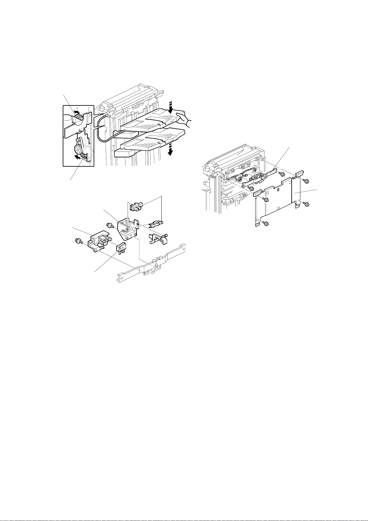
1.6 UPPER STACK HEIGHT SENSORS/TRAY 1 UPPER
LIMIT SWITCH
[B]
[D]
G565R201.WMF
[A]
[F]
[E]
[C]
[G]
G565R109.WMF
[H]
G565R110.WMF
1. External covers (☛ 1.1.1 EXTERNAL COVERS)
2. Place one hand under tray 2 (the lower tray), press in on the gear [A] to release
the tray, and then support it with your hand as it descends.
3. Place one hand under tray 1 (the upper tray), press in on the gear [B] to
release the tray, and then support it with your hand as it descends.
4. Tray 1 back fence [C] (! x 4)
5. Sensor stay [D] (! x 2, (# x 4)
6. Plastic bracket [E] (! x 1)
7. Stack height sensors [F]
8. Metal bracket [G] (! x 1)
9. Upper limit switch [H]
G565-4
Page 6
23 February, 2001 EXIT GUIDE PLATE MOTOR
1.7 EXIT GUIDE PLATE MOTOR
1. Tray 1 back fence (☛ 1.6 UPPER
STACK HEIGHT SENSORS/TRAY 1
UPPER LIMIT SWITCH)
2. Exit guide plate motor [A] (! x2, #
x1)
NOTE: Disengage the shaft of the exit
guide plate motor from the
ring.
G565R111.WMF
[A]
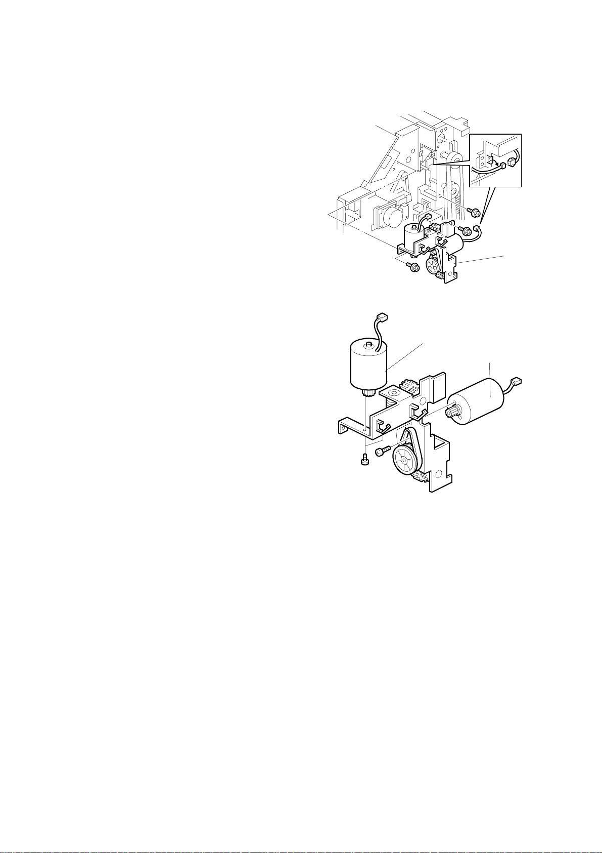
1.8 LIFT MOTORS
1. Top cover and rear cover (☛ 1.1.1
EXTERNAL COVERS)
2. Tray 1 back fence [A] (☛ 1.6 UPPER
STACK HEIGHT SENSORS/TRAY 1
UPPER LIMIT SWITCH)
3. Sensor stay [B] (! x 4)
[A]
[B]
Peripherals
G565R203.WMF
G565-5
Page 7
LIFT MOTORS 23 February, 2001
4. Motor bracket [C] (! x 3, # x 2)
[C]
G565R204.WMF
5. Tray 1 lift motor [D] (! x 2, drive belt)
6. Tray 2 lift motor [E] (! x 2, drive belt)
[D]
[E]
G565R205.WMF
G565-6
Page 8
23 February, 2001 LOWER EXIT SENSOR
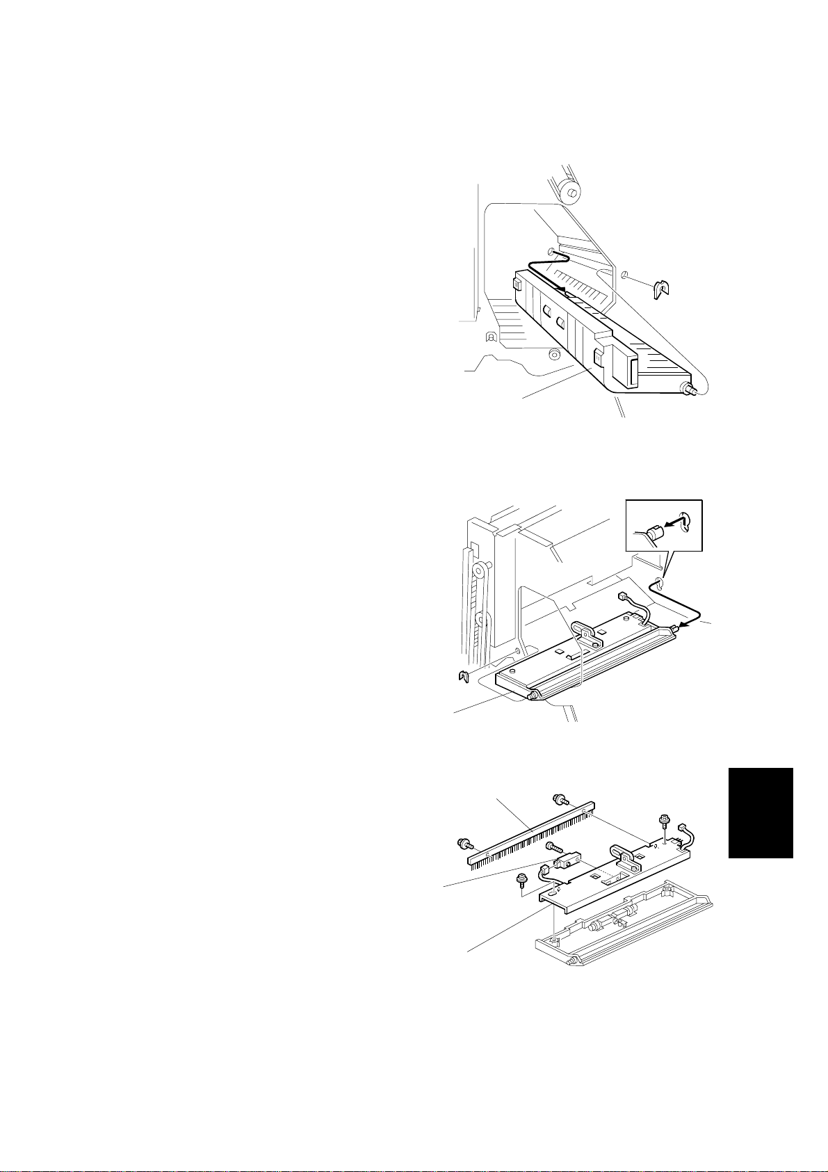
1.9 LOWER EXIT SENSOR
1. Front door, external and internal
covers. (☛ 1.1 COVERS)
2. Exit guide plate motor (☛ 1.7 EXIT
GUIDE PLATE MOTOR)
3. Guide plate [A] (" x 1)
NOTE: Pull the shaft toward you
through the round hole.
[A]
G565R112.WMF
4. Guide plate exit assembly [B] (# x 1,
" x 1)
5. Anti-static brush [C] (! x 2)
6. Bracket guide exit [D] (! x 2)
7. Lower exit sensor [E] (! x 1, # x 1)
[B]
G565R113.WMF
[C]
Peripherals
[E]
G565-7
[D]
G565R114.WMF
Page 9
LOWER STACK HEIGHT SENSORS 23 February, 2001
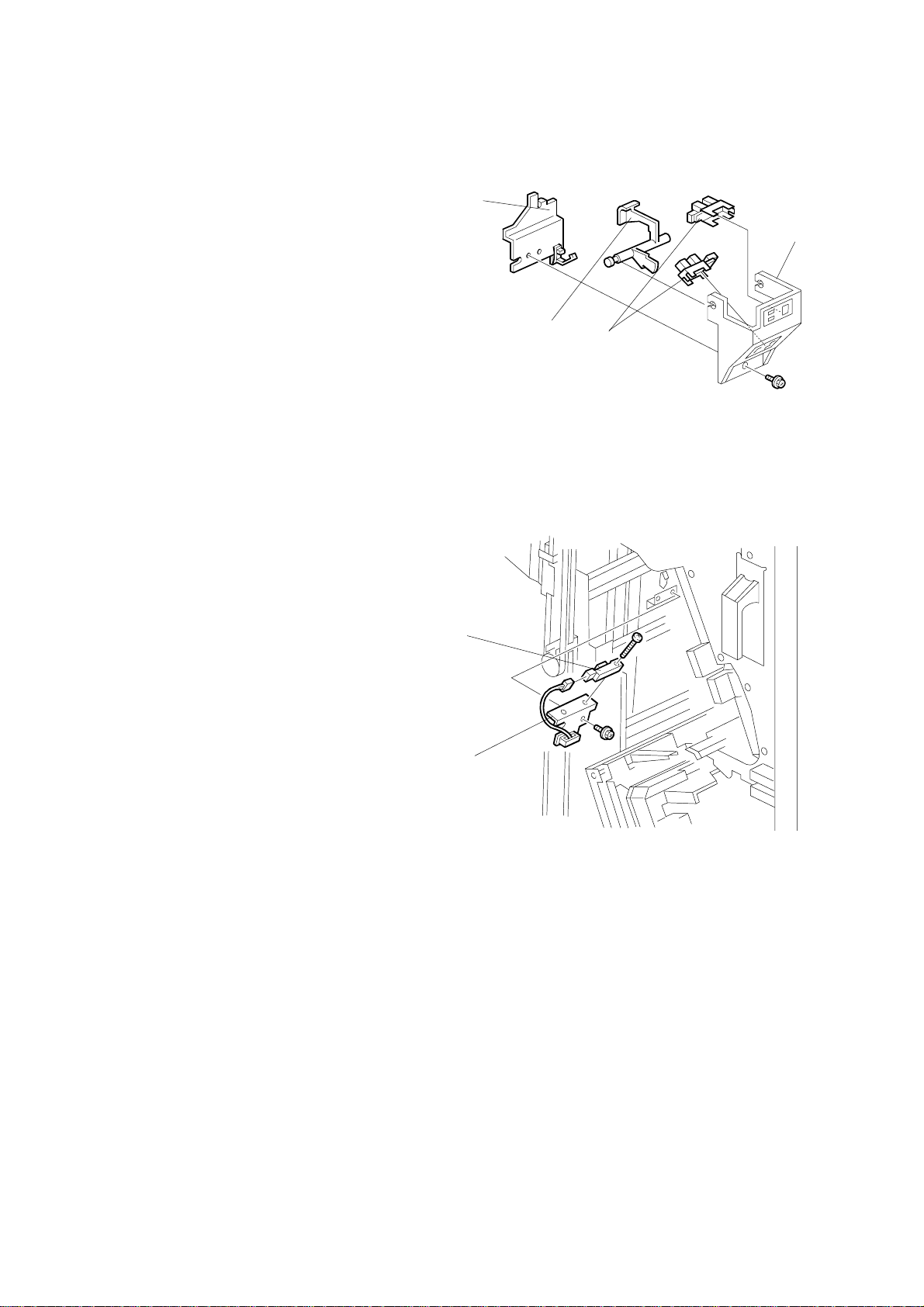
1.10 LOWER STACK HEIGHT SENSORS
1. Stapler tray (☛ 1.5 STAPLER TRAY)
[B]
2. Sensor bracket [A] (! x 1, # x 2)
3. Bracket [B] (! x 1)
4. Feeler [C]
5. Lower stack height sensors [D]
[C]
1.11 TRAY 2 SHUNT POSITION SENSOR
1. Stapler tray (☛ 1.5 STAPLER TRAY)
2. Sensor bracket [A] (! x 1, # x 1)
3. Tray 2 shunt position sensor [B] (! x 1)
[B]
[A]
[D]
G565R116.WMF
[A]
G565R202.WMF
G565-8
Page 10
23 February, 2001 STAPLER UNIT
1.12 STAPLER UNIT
1. Open the front door
2. Stapler unit [A] (! x 1, # x 2)
NOTE: Hold the stapler holder [B] with
one hand as you remove the
stapler. Do not twist or rotate
the stapler bracket as you
remove it.
[B]
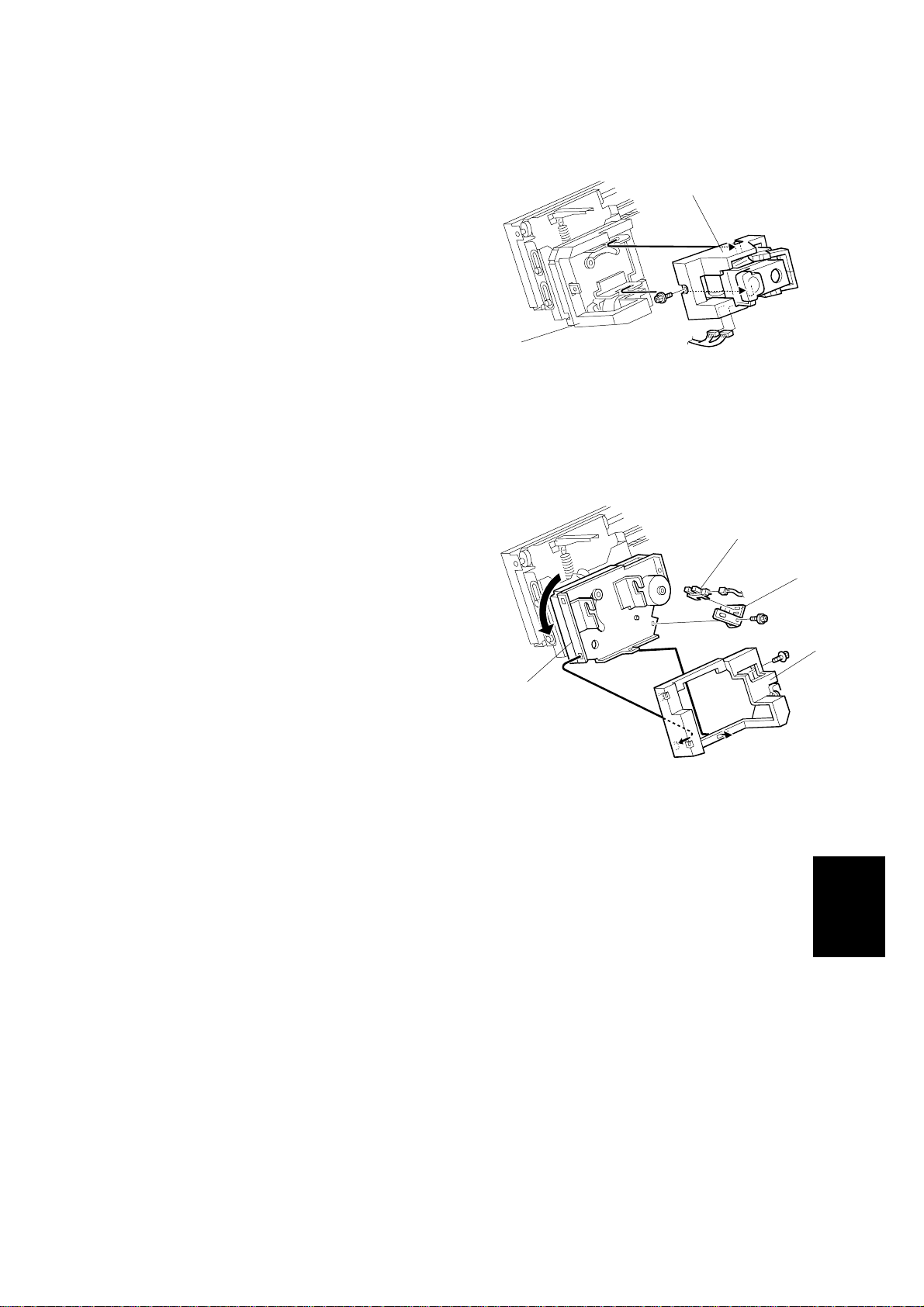
1.13 STAPLER ROTATION HP SENSOR
1. Stapler unit (☛ 1.12 STAPLER UNIT)
2. Carefully rotate the stapler holder [A].
3. Stapler cover [B] (! x 1)
4. Sensor bracket [C] (! x 1, # x 1)
[A]
G565R117.WMF
[D]
[C]
5. Stapler rotation HP sensor [D]
[B]
[A]
G565R118.WMF
Peripherals
G565-9
Page 11
TRAY 1 INTERIOR 23 February, 2001
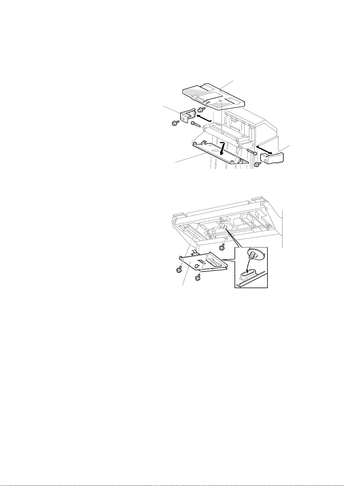
1.14 TRAY 1 INTERIOR
1.14.1 TRAY 1 COVERS
1. Tray 1 [A] (! x 1)
2. Rear tray cover [B] (! x 1)
3. Front tray cover [C] (! x 1)
4. Bottom tray cover [D] (! x 2)
5. Bottom bracket [E] (! x 3)
[A]
[B]
[C]
[D]
G565R207.WMF
[E]
G565-10
G565R208.WMF
Page 12
23 February, 2001 TRAY 1 INTERIOR
1.14.2 TRAY SHIFT SENSORS AND TRAY RELEASE SENSOR
1. Tray 1 covers (☛ 1.14.1 TRAY 1
COVERS)
2. Gear disk [A] (" x 1)
3. Tray shift sensors [B] (# x 1 each).
4. Tray release sensor [C] (# x 1)
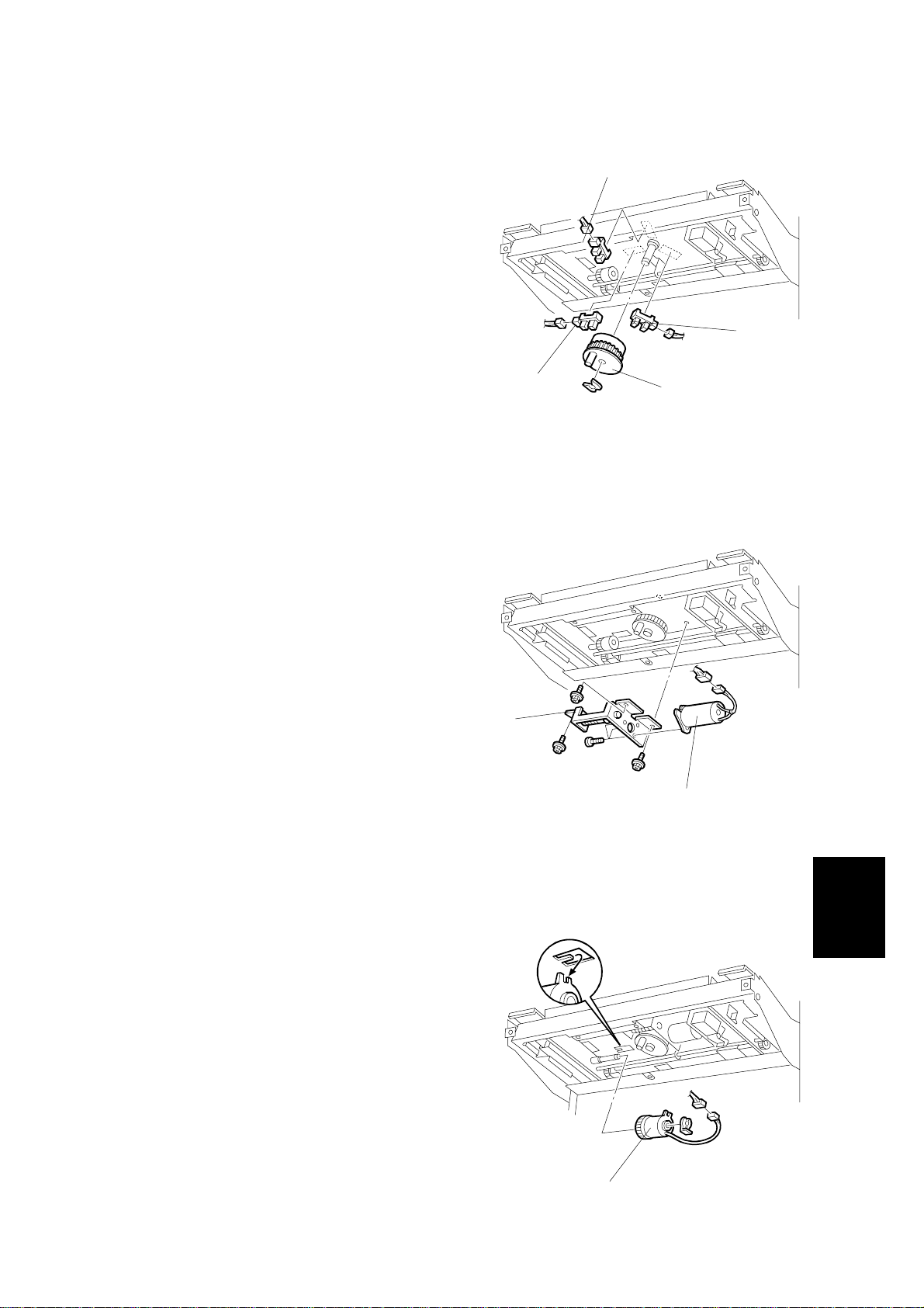
1.14.3 TRAY 1 SHIFT MOTOR
1. Tray 1 covers (☛ 1.14.1 TRAY 1
COVERS)
2. Motor bracket [A] (! x 3, # x 1)
[B]
[B]
[C]
[A]
G565R210.WMF
3. Tray 1 shift motor [B] (! x 3, belt x 1)
1.14.4 BACK FENCE LOCK CLUTCH
1. Tray 1 covers (☛ 1.14.1 TRAY 1
COVERS)
2. Back fence lock clutch [A] (" x 1, # x
1)
[A]
[B]
G565R209.WMF
Peripherals
G565-11
B352R211.WMF
[A]
Page 13

FINISHER MAIN BOARD 23 February, 2001
1.15 FINISHER MAIN BOARD
1. Rear cover (☛ 1.1.1 EXTERNAL
COVERS)
2. Main PCB [A] (! x 6, All #)
[A]
G565R206.WMF
1.16 PUNCH HOLE POSITION ADJUSTMENT
To adjust the position of the punch holes in the paper feed direction, use the
appropriate SP mode.
To adjust the horizontal position of the holes, use the spacers provided with the
punch unit.
1. Rear cover (☛ 1.1.1
EXTERNAL COVERS)
2. Punch unit [A] (! x 3, # x 5)
3. Spacers [B]
The punch position can be adjusted
by up to 4 mm using combinations
of the 3 spacers provided with the
finisher.
G565-12
[A][B]
G565R119.WMF
Page 14

23 February, 2001 JAM DETECTION
2. TROUBLESHOOTING
2.1 JAM DETECTION
Mode
Shift 1 Shift 2 Staple
!!!
!!!
!
!
!
!
!
!
!
Jam Content
Entrance sensor:
no detection
Entrance sensor:
no detection
Upper exit sensor:
no detection
Upper exit sensor:
jam
Lower exit sensor:
no detection
Lower exit sensor:
jam
Stapler tray
entrance sensor:
no detection
Stapler tray
entrance sensor:
jam
Lower tray exit
sensor: no
detection
After the exit sensor in the main machine
went off, the entrance sensor did n ot switch
on for at least 2 s.
After the entrance sensor swit ched on, it did
not remain on for at least 150 ms.
1
After the entrance sensor swit ched on, the
upper exit sensor did not remain on for at
least 59 pulses.
After the upper exit sensor swit ched on, it
did not switch off within 150 ms.
2
1
After the entrance sensor swit ched on, the
lower exit sensor did not sw it ch on within 59
pulses.
After the lower exit sensor swit ched on, it
did not switch off within 150 ms.
2
1
After the entrance sensor swit ched off, the
stapler tray entrance sensor did not switch
on within 102 pulses.*
2
After the stapler tray entrance sensor
switched on, it did not switch off within 5 9
pulses.*
1
After the transport motor switched on, t he
lower tray exit sensor did not switch on
within 1260 ms.
*1
: Timing for A4 L (differs according to paper size).
*2
: Counted by entrance motor pulses because timing differs for feed out.
Peripherals
G565-13
Page 15

DIP SWITCH SETTINGS 23 February, 2001
3. SERVICE TABLES
3.1 DIP SWITCH SETTINGS
The DIP switches should not be set to any combination other than those described
in the table below.
DPS101
1234
0000Default.
1 1 1 0 Free run. No paper.
0 0 0 1 Transportation See the note below.
NOTE: To position the shift trays for shipping, on the finisher main board set DIP
SW4 ON, cycle the main machine power off and on, then set DIP SW4
OFF. The shift trays move automatically to the shipping position. After
unpacking the machine again and switching on, turn all DIP switches off to
put the machine into factory default mode.
Mode Description
3.2 TEST POINTS
No. Label Monitored Signal
TP101 GND Ground
TP102 5 V 5 V
TP103 RX D Received command data
TP104 TXD Transmitted command data
3.3 FUSES
No. Function
FU101 Protects 24 V.
G565-14
Page 16

23 February, 2001 GENERAL LAYOUT
4. DETAILED DESCRIPTIONS
4.1 GENERAL LAYOUT
1
8
2
3
7
4
6
5
G565D118.WMF
1. Upper junction gate
2. Punch unit (option)
3. Stapler junction gate
4. Pre-stack tray
5. Stapler
6. Stapler tray
7. Tray 2
8. Tray 1
Tray junction gate: Directs paper either to the upper or lower exit. In staple mode,
the stack always goes out to the lower exit.
Stapler junction gate: Directs paper either to the lower exit or to the stapler tray.
Pre-stack tray: When staplin g multiple prints (A4 LEF, LT LEF, B5 LEF only) in the
staple mode, the first sheet of the second print waits here for the next sheet to feed
while the previous stack is stapled. After the second print is fed, the first and
second sheets are fed together to the pre-stack tray. This delay allows enough time
for the previous stack to be stapled without interrupting paper feed.
Peripherals
Shift trays: Tray 1 (upper) and tray 2 (lower) shift side to side in the sort mode,
and raise and lower to receive ejected prints.
Stapler tray jogger: Employs positioning rollers and jogger fences to align stacks
for stapling.
Punch unit. Punches holes in stacked prints.
G565-15
Page 17

DRIVE LAYOUT 23 February, 2001
4.2 DRIVE LAYOUT
4
3
2
14
13
12
11
10
1
5
6
15
7
16
9
8
G565D104.WMF
1. Tray 1 lift motor
2. Entrance roller
3. Tray 2 lift motor
4. Upper exit roller
5. Tray 1 shift motor
6. Exit guide plate motor
7. Lower exit roller
8. Tray 2 shift motor
9. Exit motor
18
10. Lower transport motor
11. Pre-stack motor
12. Upper transport motor
13. Punch motor
14. Entrance motor
15. Stack feed-out motor
16. Jogger motor
17. Stapler motor
18. Stapler rotation motor
17
G565D103.WMF
G565-16
Page 18

23 February, 2001 JUNCTION GATES
4.3 JUNCTION GATES
The two junction gates can direct paper to three destinations.
In sort/stack mode for tray 1, the tray junction
solenoid [A] is on, and the prints go to the upper
exit (tray 1 is at the upper exit for sort/stack mode).
In sort/stack mode for tray 2, both the tray junction
gate solenoid [A] and stapler junction gate solenoid
[B] are off, and prints go to the lower exit.
[A]
G565D205.WMF
[A]
In staple mode, the tray junction solenoid [A] is off and
the stapler junction gate solenoid [B] is on, and prints
go to the stapler tray.
[B]
[B]
G565D206.WMF
[A]
Peripherals
G565D207.WMF
G565-17
Page 19

TRAY SHIFTING 23 February, 2001
4.4 TRAY SHIFTING
4.4.1 TRAY SHIFT MECHANISMS
[F]
[A] [B]
[C]
[D]
[E]
G565D106.WMF
Tray 1 (Upper Tray)
In sort/stack mode, tray 1 [A] moves from side to side to separate the printed sets.
The tray 1 shift motor [B], inside the shift tray, controls the horizontal position of
tray 1 through the timing belt [C] and gear disk [D].
After one print set is delivered to tray 1, the shift motor turns on, driving the gear
disk and the arm [E], and the tray drive unit moves to one side.
Two shift sensors [F] detect when to stop this side-to-side movement. There is a
cut-out in the gear disk. The shift tray moves in one direction until one of the shift
sensors detects the cut-out. Then the shift tray stops.
The next set of prints is then delivered, and the gear disk is turned in the opposite
direction until the other shift sensor is activated.
G565-18
Page 20

23 February, 2001 TRAY SHIFTING
Tray 2 (Lower Tray)
[C]
[A]
[E]
[D]
[B]
G565D105.WMF
In sort/stack mode, tray 2 [A] moves from side to side to separate the sets of prints.
The shift mechanism for tray 2 is similar to that used for tray 1. However, when the
tray 2 shift motor [B] turns on, the arm [D] moves the entire end fence [C] from side
to side (not just the tray).
After the gear disk has turned 180 degrees, the cut-out in the gear disk enters the
tray half- turn sensor [E], and the motor stops . When the next set of prints is
delivered, the motor turns on again, and moves the tray back to its previous
position.
Peripherals
G565-19
Page 21

TRAY UP/DOWN MECHANISMS 23 February, 2001
4.5 TRAY UP/DOWN MECHANISMS
4.5.1 TRAY 1
[A]
[C]
[F]
[G]
[H]
[I]
[E]
[D]
[C]
[B]
G565D204.WMF
Introduction
The tray 1 lift motor [A] controls the vertical position of tray 1 [B] through gears and
timing belts [C].
Normal and sort/stack modes
When the ma in s witch is turned on, the tr ay is initialized at the upper position. To
do this, the tray is moved up until upper stack height sensor 1 [D] is de-actuated.
During printing, if upper stack height sensor 2 [E] is actuated, the tray 1 lift motor
lowers the tray for a specified time.
When the tray lowers during printing, th e actuator [F] will pass through the tray 1
overflow 1 sensor [G]. When the actuator drops below the sensor (to deactivate the
sensor), the machine detects that the paper stack height has exceeded the
overflow limit.
The upper limit switch for tray 1 [H] prevents the drive gear from being damaged if
the upper stack height sensor 1 should fail. If the tray is raised to the tray
positioning roller [I], the switch will automatically cut the power to the tray 1 lift
motor.
G565-20
Page 22

23 February, 2001 TRAY UP/DOWN MECHANISMS
Staple Mode
[A]
[B]
[D] [E]
[G]
[C]
[F]
G565D204.WMF
In staple mode, stapled stacks can be delivered to either tray, but they can only go
to the lower exit. So, if tray 1 is selected, tray 1 [A] moves down to the lower paper
exit.
Tray 1 lowers until the actuator [B] enters the tray 1 lower limit sensor [C]. Tray 1
then lifts up until lower stack height sensor 1 [D] is activated.
When tray 1 is moved down to the lower exit, tray 2 must be moved down out of
the way. So, tray 2 [E] is also lowered until the tray 2 shunt position sensor [F]
detects tray 2 (or the top of the paper stack in tray 2).
The method of paper height detection is the same as for the upper exit area.
When the tray lowers during printing, t he actuator will enter the tray 1 overflow 2
sensor [G]. When this happens, the machine detects that the paper stack height
has exceeded the overflow limit.
Peripherals
G565-21
Page 23

TRAY UP/DOWN MECHANISMS 23 February, 2001
Tray 1 release mechanism
When tray 1 is selected for staple mode, tray
1 must be moved down to the lower paper
exit. However, to move past the sensors at
the lower exit, the tray must be moved away
from the finisher.
To do this, the tray 1 shift motor turns until
the cut-out in the gear disk enters the tray
release sensor [A]. At this time, the arm [B]
has reached position [C], and is pushing
against the plate [D], in towards the finisher.
However, the plate is fixed, so the tray
moves out away from the finisher.
Then, the tray 1 shift motor stops, then the
tray 1 lift motor lowers tray 1.
When the tray 1 lower limit sensor is
activated (as described on the previous
page), the tray has moved past the sensors
at the lower exit. The tray 1 shift motor turns
on again until the gear disk activates the
tray shift sensor [E]. This moves the tray
back against the finisher.
[D]
[B]
[C]
[A]
G565D201.WMF
[E]
Next, tray 1 lifts until the finisher detects that
the tray is at the correct height.
When tray 1 is at the lower exit, the tray lock
solenoid [F] is on, and the lever [G] locks
the tray. This prevents the user from mov ing
the tray out of position (the first tray has
some play when it is at the lower position).
Before tray 1 goes back to the upper exit
area, the tray lock solenoid [F] turns off to
unlock the tray. In addition, the back fence
lock clutch [H] turns on to hold the back
fence [I]. This prevents the springs inside
the back fence from suddenly contracting
(these springs normally keep the tray steady
during side-to-side shift).
Then, tray 1 is released and it moves up to
the upper exit area.
[I]
G565D202.WMF
[F]
[G]
[H]
B352D203.WMF
G565-22
Page 24

23 February, 2001 TRAY UP/DOWN MECHANISMS
4.5.2 TRAY 2
[H]
[A]
[C]
[E]
[D]
[F]
[E]
[B]
[D]
[F]
[C]
Overflow condition
Normal ModeMulti Tray Staple Mode
G565D500.WMF
[G]
G565D109.WMF
The tray 2 lift motor [A] controls the vertical position of tray 2 [B] through gears and
timing belts [C].
The paper height detection is the same as for tray 1.
When the tray lowers during printing, the tray is judged to be overflowing when the
tray 2 overflow sensor 1 [D] is off and the tray 2 overflow sensor-2 [F] is on (see
‘Normal Mode’ in the above diagram).
In the multi-tray staple mode (selected by the service technician), the machine
detects that the paper stack height has exceeded the overflow limit when the
actuator [E] enters the tray 2 overflow 1 sensor [D].
The lower limit sensor [G] for tray 2 detects when tray 2 is at its lowest limit and
stops the tray 2 lift motor.
The function of the tray 2 upper limit switch [H] is the same as for tray 1.
Peripherals
G565-23
Page 25

TRAY UP/DOWN MECHANISMS 23 February, 2001
4.5.3 PRE-STACK MECHANISM
[B]
[A]
[C]
[D]
G565D200.WMF
NOTE: This feature is available only when using A4 L, LT L, and B5 L.
During stapling, the main machine must wait. This mechanism reduces the wait by
holding the first two sheets of a job while the previous job is still being stapled. It
only works during the second and subsequent sets of a multi-set print job.
The pre-stack junction gate solenoid [A] switches on after the first sheet activates
the entrance sensor. This directs the sheet to the pre-stack tray [B].
The pre-stack feed roller [C] stops for a specifie d time after the trailing edge of the
paper has passed through the entrance sensor and stops the paper from leaving
the pre-stack tray.
At the same time, the pre-stack junction gate solenoid switches off, and the second
sheet is sent to the paper guide [D]. The pre-stack feed roller (controlled by the
pre-stack motor) starts to rotate again for a specified time after the trailing edge of
the second page has been passed through the entrance sensor, and then both
sheets are sent to the stapler tray together.
G565-24
Page 26

23 February, 2001 JOGGER UNIT PAPER POSITIONING MECHANISM
4.6 JOGGER UNIT PAPER POSITIONING MECHANISM
[C]
[E]
[A]
[B]
[F]
[D]
G565D110.WMF
In staple mode, each sheet of print paper is vertically and horizontally aligned when
it arrives in the stapler tray.
Vertical Paper Alignment
After the trailing edge of the paper passes the stapler tray entrance sensor [A], the
positioning roller solenoid [B] is energized for a specified time to push the
positioning roller [C] into contact with the paper.
The positioning roller rotates to push the paper back and align the trailing edge of
the paper against the stack stopper [D].
Horizontal Paper Alignment
When the start key is pressed , the jogger motor [E] turns on and the jogger fences
[F] move to the waiting position, which is 8 mm wider on both sides than the
selected paper.
When the trailing edge of the paper passes the stapler tra y e ntrance sensor, the
jogger motor turns on to move the jogger fences 5 mm towards the paper. After a
short time, the jogger motor turns on again for the horizontal paper alignment then
returns to the waiting position.
G565-25
Peripherals
Page 27

STAPLER MECHANISM 23 February, 2001
4.7 STAPLER MECHANISM
4.7.1 STAPLER MOVEMENT
[D]
[B]
[A]
[B][E]
G565D112.WMF
[C]
G565D113.WMF
The stapler can be moved from side to side or rotated according to the
requirements of the selected stapling mode.
Stapler Rotation
After the start key is pressed, the stapler rotation motor [A] rotates the staple unit
[B] until the stapler rotation HP sensor [C] is activated. Then, the stapler moves
from front to rear of the finisher.
When oblique stapling at one pos ition has been selected, after the stapler moves
to the stapling position, the stapler rotation motor rotates the stapler 45 degrees
(clockwise) at the stapling positio n before the stapler fires.
Side-to-Side Movement
The stapler motor [D] moves the stapler from side to side. After the start key is
pressed, the stapler moves from its home position to the stapling position.
The amount of movement required to reach the stapling position is determined by
the size of the selected paper. If the two-staple mode is selected, the stapler
moves to the front stapling position first, and then moves to the rear stapling
position. However, for the next print set, it staples in the reverse order.
After the stapling job is finished, the stapler returns to its home position,
determined by the stapler HP sensor [E].
G565-26
Page 28

23 February, 2001 STAPLER MECHANISM
4.7.2 STAPLER
[D]
[B]
[C]
G565D208.WMF
[A]
The staple hammer is driven by the stapler hammer motor [A] inside the stapler.
As soon as the paper stack is aligned, the staple hammer motor starts. When
stapling is finished, the staple hammer HP sensor [B] is turned on, and the staple
hammer motor then stops.
The staple end sensor [C] detects the staple end condition and whether the staple
cartridge is installed or not. If a stapler cassette is not installed, or after the stapler
cassette runs out of staples, a message is displayed in the operation panel. If this
condition is detected during a print job, the indicator will appear, but the print job
will not stop.
The staple position sensor [D] detects if there is a staple sheet at the stapling
position. After a new staple cartridge is installed, the staple hammer motor turns on
to transfer the staple sheet until the staple position sensor is activated by the staple
sheet.
If a staple jam occurs and overloads the motor, this causes a staple jam message
to appear on the operation panel.
Peripherals
G565-27
Page 29

STAPLER MECHANISM 23 February, 2001
4.7.3 FEED OUT AND TRANSPORT
[A]
[C]
[I]
[B]
G565D115.WMF
[D]
[G]
[F]
[H]
G565D114.WMF
When stapling starts, the exit guid e plate motor [A] switches on and opens the exit
guide plate [B], so that the stapled stack can exit to the tray. The exit guide plate
sensor [C] detects when to switch off the exit guide plate motor.
After the prints have been stapled, the stack feed-out motor [D] starts. The pawl [E]
on the stack feed out belt [F] lifts the stapled set and feeds it to the tray [G].
The exit guide plate closes at a specified interval after the stapled prints have
started to feed out. Then the exit roller takes over the stack feed-out. The stack
feed-out motor turns off when the pawl actuates the stack feed-out belt home
position sensor [H].
[E]
When tray 1 is passing this area on its way back up to the upper exit, the exit guide
safety switch [I] cuts power to the tray lift motor if the guide is opened too far. This
prevents damage to the user’s fingers if they are inside the lower exit when the tray
is moving up.
G565-28
Page 30

23 February, 2001 PUNCH UNIT (OPTIONAL)
4.8 PUNCH UNIT (OPTIONAL)
The punch unit punches holes in printed sheets, one by one. The punch unit is
provided with a new punch mechanism to improve the accuracy of punching.
[A]
[E]
[D]
[C]
G565D102.WMF
[B]
[I]
G565D101.WMF
[F]
4.8.1 PUNCH DRIVE MECHANISM
The punch drive mechanism is driven by the punch motor [A]. Each sheet is
positioned and punched by pressure f rom above. A certain time after the trailing
edge of the paper passes through the finisher entrance sensor [B], the punch
motor turns on and the paper stops. Then the punch clutch [C] turns on to make
the punch holes.
[H]
[G]
Peripherals
The home position is detected by the punch HP sensor [D]. When the cut-out in the
punch shaft disk [E] enters the punch HP sensor, the punch clutch turns off.
When the finisher has received the command that changes the number of punch
holes, the punch hole motor [F] turns on until the disk changes the status of the
punch hole switch [G] (until it switches on or off). This indicates that the cover [H]
and the punch cam [I] have moved to one side or the other to change the number
of holes.
G565-29
Page 31

PUNCH UNIT (OPTIONAL) 23 February, 2001
4.8.2 PUNCH WASTE COLLECTION
[A]
[B]
[C]
G565D153.WMF
Waste punchouts are collected in the punch waste hopper [A] below the punch unit
inside the finisher.
When the top of the punchout waste in the hopper reaches and actuates the
hopper sensor [B], a message will be displayed on the operation panel after the
current job is completed.
This sensor also detects whether the punch waste hopper is installed. When the
waste hopper is taken out, the arm [C] moves down and this will actuate the sensor
and display a message in the operation panel. This message is the same as for the
hopper full condition.
G565-30
Page 32

ABC
D
EF
GH
POINT TO POINT WIRING DIAGRAM (Two-tray Finisher: G565)
24V
24V
24V
1
Main Unit
GND
GND
GND
GND
TXD
GND
RXD
N.C
N.C
N.C
N.C
N.C
N.C
N.C
Front Door Safety Sw
Entrance Cover Sn.
Entrance Sensor
Staple Tray Entrance Sn.
2
Upper Stack Height 1 Sn.
Upper Stack Height 2 Sn.
CN1-8
CN2-9
-7
-6
-5
-4
-3
-2
-1
-8
-7
-6
-5
-4
-3
-2
-1
(SW6)
S1
S2
S19
S14
S15
CN203-1
CN200-1
CN202-1
CN706-1
CN705-1
-2
-3
CN203-3
-2
-3
-2
-3
-2
-3
-2
-3
CN203-1
-2
-1
-2
-3
(SW3)
Tray 1 Upper Limit Sw
CN205-1
Upper Exit Sn.
Upper Cover Sn.
Lower Exit Sn.
CN702-1
3
Lower Stack Height 2 Sn.
Lower Stack Height 1 Sn.
S18
S17
CN701-1
S23
S13
-2
-3
-2
-3
Tray 2 Overflow 2 Sn.
CN404-1
Tray 1 Overflow 2 Sn.
S29
-2
-3
Shift Mode Sn.
CN402-1
Tray 1 Overflow 1 Sn.
S31
-2
-3
Tray 1 Lower Limt Sn.
Tray 2 Overflow 1 Sn.
4
Tray 2 Shunt Position Sn.
S10
CN608-3
-2
-1
Tray 2 Lower Limit Sn.
Stack Feed-out H.P Sn.
Staple Tray Paper Sn.
Stapler H.P Sn.
Jogger H.P Sn.
CN303-1
S20
CN100-1
S35
-2
-3
-2
-3
S5
Stapler Rotation H.P Sn.
5
Front Set Sw (SW7)
Rear Set Sw (SW8)
CN204-1
CN100-1
CN304-1
S24
-2
-3
-2
-3
S6
S28
S25
S7
S8
S22
-2
-3
S21
Punch Motor
Punch CL
Punch H.P Sn.
Punch Hopper Sn.
6
Punch Hole Sw
Punch Hole Motor
CL
2
CN605-1
S12
S11
M17
-2
-3
CN512-3
CN510-6
CN508-1
-2
-3
CN403-1
-2
-3
CN405-1
-2
-3
CN507-1
-2
-3
CN506-3
CN509-1
-2
-3
CN305-1
-2
-3
CN308-3
CN309-1
-2
-3
CN704-2
CN704-1
CN703-2
CN703-1
M9
-2
-3
-4
-5
-6
-7
-8
SW5
-2
-1
-5
-4
-3
-2
-1
-2
-1
-2
-1
CN603-2
CN602-1
CN605-1
CN604-1
CN601-1
CN606-1
CN512-1
-2
-3
CN510-1
-2
-3
-4
-5
-6
CN506-1
-2
-3
CN308-1
-2
-3
CN704-1
CN704-2
CN703-1
CN703-2
-3
-4
-5
-2
-2
-3
-4
-5
-6
-7
-8
-2
-3
-2
-3
-2
-3
-4
CN101-1
CN102-1
CN103-1
CN104-10
CN104-3
CN132-10
CN132-7
CN132-2
CN105-6
CN105-3
CN106-9
CN106-6
CN129-15
CN129-11
CN129-7
CN129-3
CN117-13
CN117-10
CN117-3
CN108-9
CN108-6
CN108-3
CN109-6
CN109-3
CN134-4
CN130-8
CN130-2
CN131-15
CN131-3
CN107-4
+24V
-2
+24V
-3
+24V
-4
GND
-5
GND
-6
GND
-7
N.C
-8
N.C
N.C
-2
GND
-3
TXD
-4
GND
-5
RXD
-6
N.C
-7
N.C
-8
N.C
-9
N.C
24V
-2
[!24] Front Door Safety Sw
+5V
-9
["5] Entrance Cover Sn.
-8
GND
-7
N.C
-6
+5V
-5
["5] Entrance Sensor
-4
GND
+5V
-2
GND
-1
[!5] Staple Tray Entrance Sn.
+5V
-9
[!5] Upper Stack Height 1 Sn.
-8
GND
+5V
-6
[!5] Upper Stack Height 2 Sn.
-5
GND
-4
N.C
-3
N.C
-1
[!5] Tray 1 Upper Limit Sw
+5V
-5
["5] Upper Exit Sn.
-4
GND
+5V
-2
["5] Upper Cover Sn.
-1
GND
GND
-8
[!5] Lower Exit Sn.
-7
+5V
+5V
-5
[!5] Lower Stack Height 2 Sn.
-4
GND
-3
+5V
-2
[!5] Lower Stack Height 1 Sn.
-1
GND
+5V
-14
[!5] Tray 1 Overflow 2 Sn.
-13
GND
-12
N.C
+5V
-10
[!5] Tray 1 Overflow 2 Sn.
-9
GND
-8
N.C
+5V
-6
[!5] Shift Mode Sn.
-5
GND
-4
N.C
+5V
-2
[!5] Tray 1 Overflow 1 Sn.
-1
GND
+5V
-12
[!5] Tray 1 Lower Limt sn.
-11
GND
+5V
-9
[!5] Tray 2 Overflow 1 Sn.
-8
GND
-7
N.C
-6
+5V
-5
[!5] Tray 2 Shunt Position Sn.
-4
GND
+5V
-2
[!5] Tray 2 Lower Limit Sn.
-1
GND
+5V
-8
["5] Stack Feed-out H.P Sn.
-7
GND
+5V
-5
[!5] Jogger H.P Sn.
-4
GND
+5V
-2
["5] Staple Tray Paper Sn.
-1
GND
+5V
-5
[!5] Stapler H.P Sn.
-4
GND
+5V
-2
[!5] Stapler Rotation H.P Sn.
-1
GND
Set Deteciton
-3
Set Deteciton
-2
Set Deteciton
-1
GND
N.C
-7
GND
-5
+24V
-4
["5] Punch Motor ON/OFF
-3
["5] Punch LD
["24] Punch CL
-1
+24V
GND
-14
GND
-13
Punch Unit Detection
-12
Punch Unit Detection
-11
Punch Unit Detection
-10
Punch Unit Detection
-9
GND
-8
GND
-7
N.C
-6
+5V
-5
["5] Punch H.P Sn.
-4
GND
GND
-2
["5] Punch Hopper Sn.
-1
+5V
GND
-3
["5] Punch Hole SW
-2
+24V
-1
["24] Punch Hole Motor ON/OFF
Main (PCB 1)
Entrance Motor: A [0-24]
Entrance Motor: A [0-24]
Entrance Motor: B [0-24]
Entrance Motor: B [0-24]
Upper Transport Motor: A [0-24]
Upper Transport Motor: A [0-24]
Upper Transport Motor: B [0-24]
Upper Transport Motor: B [0-24]
Lower Transport Motor: A [0-24]
Lower Transport Motor: A [0-24]
Lower Transport Motor: B [0-24]
Lower Transport Motor: B [0-24]
Exit Motor: A [0-24]
Exit Motor: A [0-24]
Exit Motor: B [0-24]
Exit Motor: B [0-24]
Tray2 Lift Motor: + ["24V]
Tray2 Lift Motor: - ["24V]
Tray1 Lift Motor: + ["24V]
Tray1 Lift Motor: - ["24V]
Exit Guide Plate Motor: + ["24V]
Exit Guide Plate Motor: - ["24V]
Stack Feed-out Motor: A [0-24]
Stack Feed-out Motor: A [0-24]
Stack Feed-out Motor: B [0-24]
Stack Feed-out Motor: B [0-24]
Jogger Motor: A [0-24]
Jogger Motor: A [0-24]
Jogger Motor: B [0-24]
Jogger Motor: B [0-24]
Tray2 Shift Motor: - ["24V]
Tray2 Shift Motor: + ["24V]
Tray2 Upper Limit SW [!24V]
Tray2 Upper Limit SW [!24V]
Tray2 Half-turn Sn. ["5]
Staple Rotation Motor: A [0-24]
Staple Rotation Motor: A [0-24]
Staple Rotation Motor: B [0-24]
Staple Rotation Motor: B [0-24]
Stapler Motor: A [0-24]
Stapler Motor: A [0-24]
Stapler Motor: B [0-24]
Stapler Motor: B [0-24]
Pre-stack Motor: A [0-24]
Pre-stack Motor: A [0-24]
Pre-stack Motor: B [0-24]
Pre-stack Motor: B [0-24]
Tray Shift 2 Sn. ["5]
Staple Mode Sn. [!5]
Tray Shift 1 Sn. [!5]
Tray Release Sn. [!5]
Tray Lock Sol. ["24]
Back Fence Lock CL ["24]
Tray 1 Shift Motor- ["24]
Tray 1 Shift Motor+ ["24]
Tray 1 Safety SW [!24]
Tray 1 Safety SW [!24]
Tray Junction Gate Sol. ["24]
Positioning Roller Sol. ["24]
Pre-stack Juction Gate Sol. ["24]
Stapler Junction Gate Sol. ["24]
Exit Guide Plate Open Sn. [!5]
Exit Guide Safety SW [!24]
Staple Hammer Motor-B [0-24]
Staple Hammer Motor-B [0-24]
Staple Hammer Motor+B [0-24]
Staple Hammer Motor+B [0-24]
Staple Hummer H.P Sn. [!5]
Staple Position Sn. [!5]
Staple End Sn. [!5]
Punch Unit
+24V
+24V
+24V
+24V
+24V
+24V
+24V
+24V
+24V
+24V
+24V
+24V
+24V
+24V
GND
+24V
+24V
+24V
+24V
+24V
+24V
GND
GND
GND
GND
+24V
+24V
+24V
+24V
+24V
GND
+24V
GND
CN121-1
-2
-3
-4
-5
-6
CN110-1
-2
CN111-1
CN113-1
CN112-1
CN114-1
CN115-1
CN116-1
CN109-8
CN118-1
CN128-1
CN119-1
CN133-1
CN127-1
CN120-1
CN124-1
CN125-1
CN126-1
CN123-4
CN122-5
-3
-4
-5
-6
-7
-2
-3
-4
-5
-6
-7
-2
-3
-4
-5
-6
-7
CN501-1
-2
-3
CN401-2
-4
-5
-6
CN510-2
-7
-8
CN301-8
-2
-3
CN301-1
-4
-5
-6
-7
-8
CN217-7
-9
-10
-11
-12
-13
-14
-15
CN504-5
-2
-3
-4
-5
-6
-7
CN504-3
-8
-9
CN216-7
-2
-3
-4
-5
-6
-7
CN227-7
-9
-10
-11
-12
-13
-14
-2
-3
-4
-5
-6
CN207-13
-2
-3
-4
-5
-6
-7
-8
-9
-10
-11
-12
-13
CN208-8
-2
-3
-4
-5
-6
-7
-8
CN206-11
-2
-3
-4
-5
-6
-7
-8
CN206-3
-9
-10
-11
-2
-2
-2
-2
-2
-3
-4
-5
-6
-7
-8
-3
-2
-1
-4
-3
-2
-1
CN501-2
-2
-1
-1
-9
-5
-7
-11
-6
-5
-4
-3
-2
-1
-4
-2
-1
-6
-5
-4
-3
-2
-1
-6
-5
-4
-3
-2
-1
-12
-11
-10
-9
-8
-6
-5
-4
-3
-2
-1
-7
-5
-4
-2
-1
-9
-7
-5
-2
-1
-1
CN401-1
-2
CN510-1
-2
CN301-4
-3
CN301-11
-7
-5
-1
CN217-1
-2
-3
-4
-5
-6
-7
CN606-2-1CN606-1
CN504-1
-2
CN504-3
-4
-5
CN216-1
-2
-3
-4
-5
-6
-7
CN227-1
-2
-3
-4
-5
-6
-7
CN207-1
-2
-3
-4
-5
-6
-8
-9
-10
-11
-12
-13
CN208-1
-2
-4
-5
-7
-8
CN206-1
-3
-5
-7
CN310-4
CN311-5
-3
-2
-1
-4
-3
-2
-1
N.C
N.C
N.C
N.C
N.C
N.C
N.C
N.C
5V
N.C
N.C
+5V
+5V
N.C
+5V
+5V
24V
N.C
24V
N.C
N.C
N.C
N.C
N.C
N.C
N.C
N.C
24V
5V
N.C
N.C
N.C
+5V
M1
Entrance Motor
M13
Upper Transport Motor
M5
Lower Transport Motor
M2
Exit Motor
M6
Tray 1 Lift Motor
M15
M3
M12
Stack Feed-out Motor
Jogger Motor
M4
-2
M10
Stapler Rotation Motor
M11
Stapler Motor
Pre-Stack Motor
M8
SOL
1
CL1
M14
SOL
5
SOL
SOL
2
SOL
M16
Tray 2 Lift Motor
Exit Guid Plate Motor
Tray 2 Shift Motor
M7
CN607-3
-2
-1
CN412-3
-2
-1
CN413-3
-2
-1
CN414-3
-2
-1
CN414-3
-2
-1
Tray Lock Sol.
Back Fence Lock CL
Tray 1 Shift Motor
Tray Junction Gate Sol.
Positioning Roller Sol.
3
Pre-stack Junction Gate Sol.
Stapler Junction Gate Sol.
4
CN503-3
-2
-1
(SW1)
Exit Guide Safety Sw
Staple Hammer Motor
[ ]
(SW4)
(SW4)
S9
Tray 2 Half-turn Sn.
S27
Tray Shift 2 Sn.
S30
Staple Mode Sn.
S26
Tray Shift 1 Sn.
S16
Tray Release Sn.
(SW2)
(SW2)
S3
Exit Gide Plate Open Sn.
Symbol Table
DC Line
Pulse Signal
Signal Direction
Active High
"
Active Low
!
Signal Level
Tray 2 Uppre Limit SW
Tray 1 Safety Sw
1
2
3
4
5
6
Staple Unit
ABC
D
EF
GH
Page 33

ELECTRICAL COMPONENT LAYOUT (G565)
15
14
13
12
16
11
17
1
2
3
4
5
6
7
8
9
10
G565D901.WMF
28
27
26
18
19
30
29
20
21
22
23
24
25
G565D902.WMF
Page 34

44
41
40
39
38
37
36
42
43
35
34
31
32
33
G565D903.WMF
60
59
58
61
62
57
56
55
54
45
46
47
48
49
50
51
52
53
G565D251.WMF
Page 35

G565D904.WMF
68
63
64
65
66
67
Page 36

ELECTRICAL COMPONENT DESCRIPTION (G565)
Symbol Description Index No. P-to-P
Motors
M1 Entrance 40 F1
M2 Exit 31 F2
M3 Exit guide plate 30 G2
M4 Jogger 33 F3
M5 Lower transport 37 F1
M6 Tray 2 lift 44 G2
M7 Tray 2 shift 24 G3
M8 Pre-stack 38 G4
M9 Punch 64 B5
M10 Stapler rotation 54 F3
M11 Stapler 34 F3
M12 Stack feed-out 32 F2
M13 Upper transport 39 F1
M14 Tray 1 shift 8 F5
M15 Tray 1 lift 43 F2
M16 Staple hammer 57 G6
M17 Punch hole 68 B6
Sensors
S1 Entrance cover 46 B2
S2 Entrance 47 B2
S3 Exit guide plate open 18 G6
S4 Staple position 61 E6
S5 Jogger HP 48 B4
S6 Tray 2 overflow-2 26 B3
S7 Tray 2 overflow-1 27 B4
S8 Tray 2 lower limit 25 B4
S9 Tray 2 half-turn 22 G3
S10 Tray 2 shunt position 23 B4
S11 Punch hopper 63 B6
S12 Punch HP 65 B6
S13 Lower exit 19 B3
S14 Upper stack height 1 2 B2
S15 Upper stack height 2 3 B2
S16 Tray release 16 G4
S17 Lower stack height 1 20 B3
S18 Lower stack height 2 21 B3
S19 Staple tray entrance 52 B2
S20 Staple tray paper 51 B5
S21 Stapler rotation HP 55 B5
S22 Stack feed-out HP 62 B4
S23 Upper cover 45 B3
S24 Upper exit 1 B3
S25 Tray 1 lower limit 11 B4
S26 Tray shift 1 4 G4
Page 37

Symbol Description Index No. P-to-P
S27 Tray shift 2 5 G4
S28 Shift mode 14 B3
S29 Tray 1 overflow-2 12 B3
S30 Staple mode 6 G4
S31 Tray 1 overflow-1 15 B4
S32 Staple hammer HP 60 E6
S34 Staple end 58 E6
S35 Stapler HP 56 B5
Selenoids
SOL1 Tray lock 7 F4
SOL2 Pre-stac k junctio n gate 35 F5
SOL3 Positioning roller 36 G5
SOL4 Stap ler junction gate 41 G5
SOL5 Tray junct ion gate 42 F5
Switches
SW1 Exit guide safety 29 G6
SW2 Tray 1 safety 9 G5
SW3 Tray 1 upper limit 17 B2
SW4 Tray 2 upper limit 28 G3
SW5 Punch hole 67 C6
SW6 Front door safety 53 B2
SW7 Front set 50 B5
SW8 Rear set 49 B5
Electrical Clutches
CL1 Back fence lock 10 G4
CL2 Punch 66 B5
PCBs
PCB1 Main 13 D4
PCB2 Stapler Sensor 59 NA
 Loading...