

Page 1

TWO-TRAY FINISHER
(Machine Code: B352)
Page 2
26 January, 2001 COVERS
1. REPLACEMENT AND ADJUSTMENT
1.1 COVERS
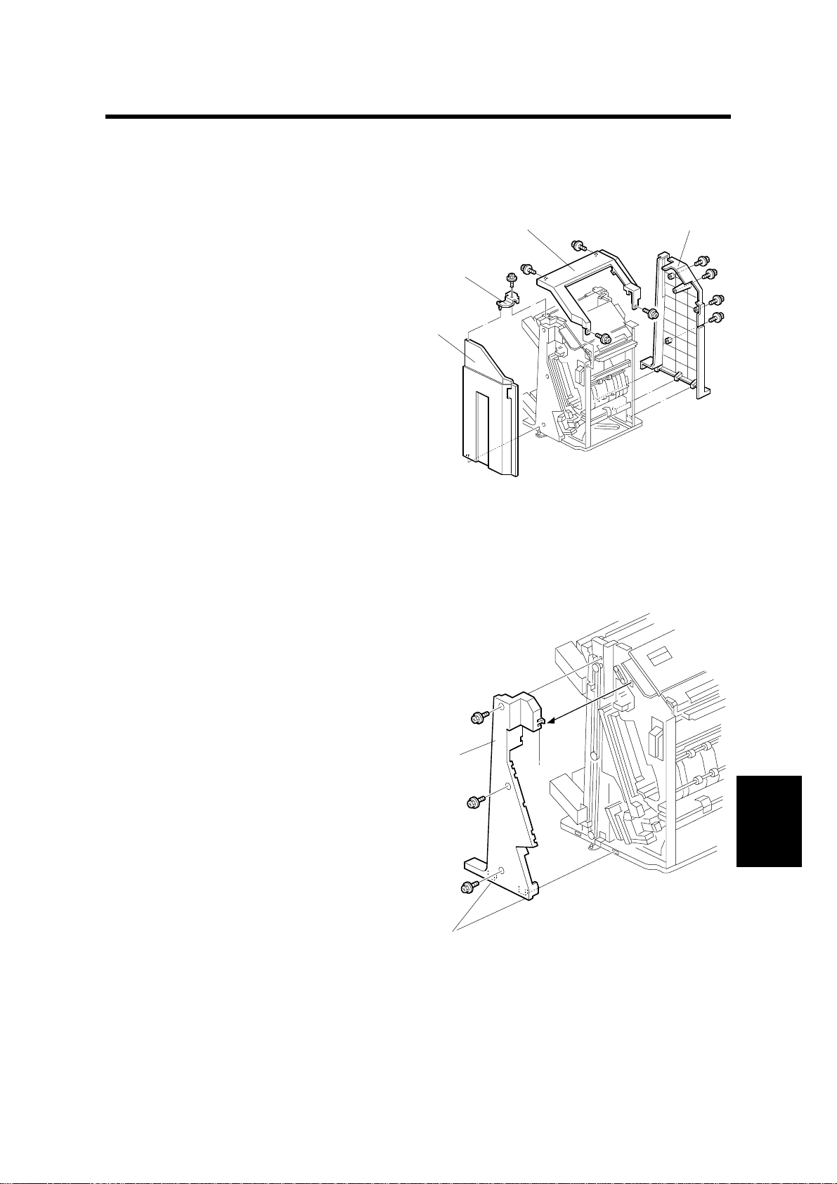
1.1.1 EXTERNAL COVERS
1. Top cover [A] (! x4)
If the shift tray below is blocking the
screw hole, remove the shift
tray.
2. Bracket [B] (! x1)
3. Front door [C]
4. Rear cover [D] (! x4)
[A]
[B]
[C]
[D]
B352R101.WMF
1.1.2 INNER COVER
1. Front cover (☛ 1.1.1)
2. Inner cover [A] (! x3, tabs [B] x3)
[A]
[B]
[B]
Peripherals
B352R102.WMF
B352-1
Page 3

POSITIONING ROLLER 26 January, 2001
1.2 POSITIONING ROLLER
1. Open the front door.
2. Positioning roller [A] (" x1)
3. Belt [B]
[B]
[A]
B352R103.WMF
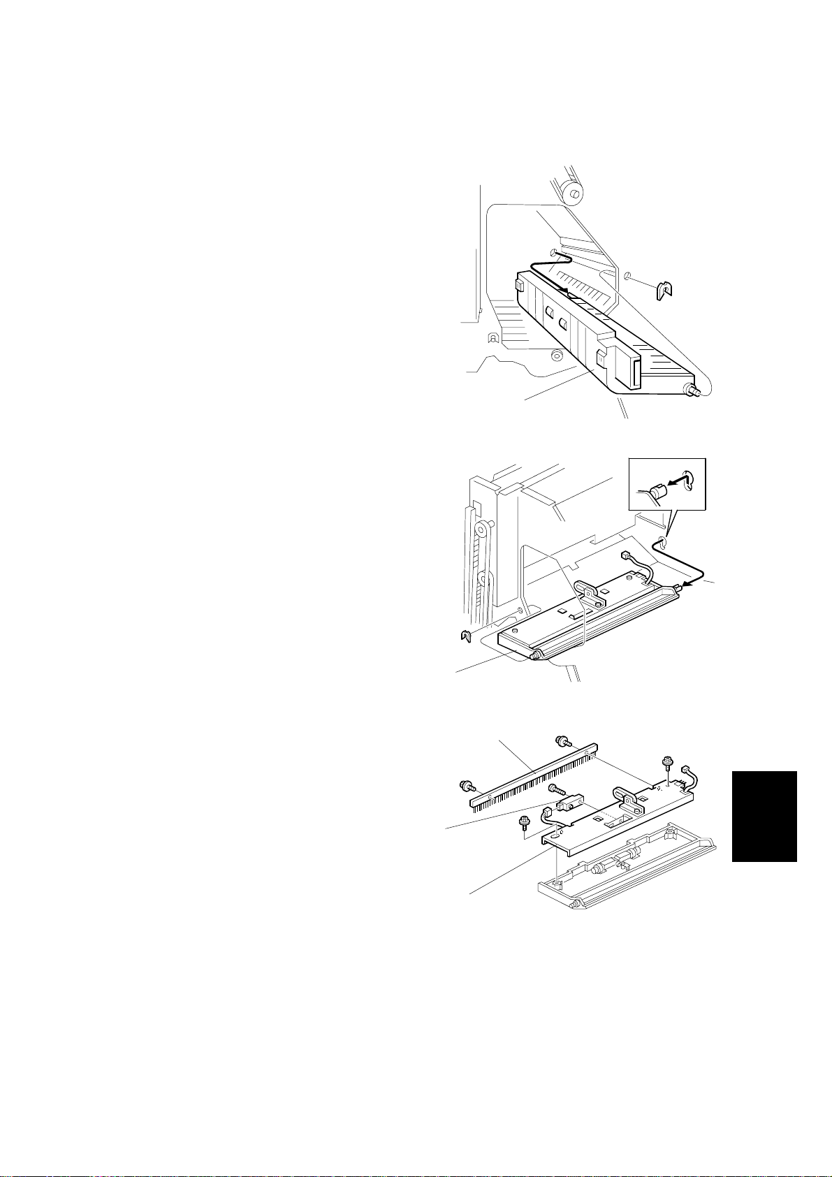
1.3 TRAY 1 EXIT SENSOR
1. Top cover (☛ 1.1.1)
2. Open transport door [A]
3. Bracket [B] (! x1, (# x1)
4. Tray 1 exit sensor [C]
[B]
[C]
[A]
B352R104.WMF
B352-2
Page 4
26 January, 2001 ENTRANCE SENSOR/STAPLER TRAY ENTRANCE SENSOR
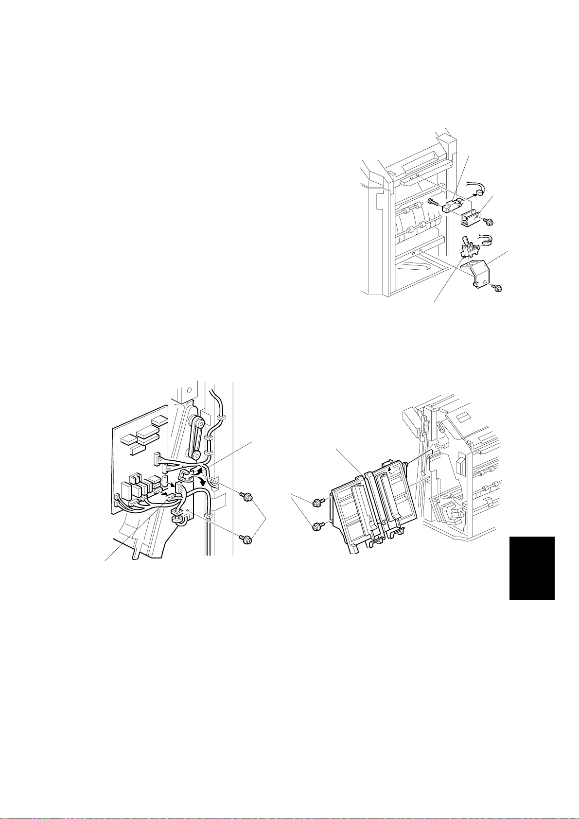
1.4 ENTRANCE SENSOR/STAPLER TRAY ENTRANCE
SENSOR
1. Entrance sensor bracket [A] (! x1, # x1)
2. Entrance sensor [B] (! x1)
3. Stapler tray entrance sensor bracket [C] (! x1,
# x1)
4. Stapler tray entrance sensor [D]
1.5 STAPLER TRAY
[D]
[B]
[A]
[C]
B352R105.WMF
[A]
[C]
[E]
[D]
[B]
B352R106.WMF
1. External covers, front door, inner cover (☛ 1.1.1, 1.1.2)
2. Two clamps [A]
3. Harnesses [B] (# x8)
4. Stapler tray [C] (! x2 [D], ! x2 [E])
At the front of the finisher, pull the stapler tray toward you and lift it out.
B352R107.WMF
Peripherals
B352-3
Page 5

UPPER STACK HEIGHT SENSORS/TRAY 1 UPPER LIMIT SWITCH 26 January, 2001
1.6 UPPER STACK HEIGHT SENSORS/TRAY 1 UPPER
LIMIT SWITCH
[B]
[D]
[A]
B352R201.WMF
[F]
[E]
[G]
B352R109.WMF
[H]
B352R110.WMF
1. External covers (☛ 1.1.1)
2. Place one hand under tray 2 (the lower tray), press in on the gear [A] to release
the tray, and then support it with your hand as it descends.
3. Place one hand under tray 1 (the upper tray), press in on the gear [B] to
release the tray, and then support it with your hand as it descends.
[C]
4. Tray 1 back fence [C] (! x4)
5. Sensor stay [D] (! x2, (# x4)
6. Plastic bracket [E] (! x1)
7. Stack height sensors [F]
8. Metal bracket [G] (! x1)
9. Upper limit switch [H]
B352-4
Page 6
26 January, 2001 EXIT GUIDE PLATE MOTOR
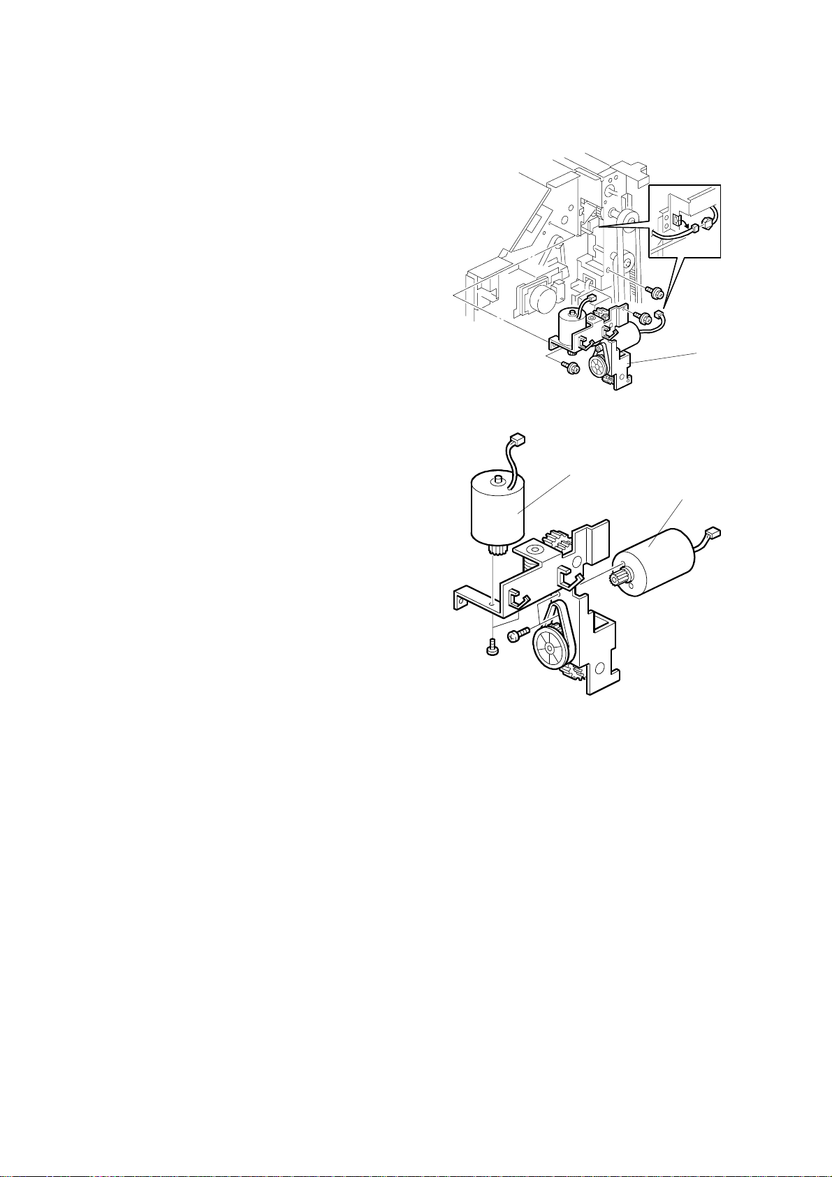
1.7 EXIT GUIDE PLATE MOTOR
1. Tray 1 back fence (☛ 1.6)
2. Exit guide plate motor [A] (! x2, # x1)
Disengage the shaft of the exit guide plate motor
from the ring.
1.8 LIFT MOTORS
1. Top cover and rear cover (☛ 1.1.1)
2. Tray 1 back fence [A] (☛ 1.6)
3. Sensor stay [B] (! x4)
[B]
[A]
B352R111.WMF
[A]
B352-5
Peripherals
B352R203.WMF
Page 7
LIFT MOTORS 26 January, 2001
4. Motor bracket [C] (! x3, # x 2)
[C]
B352R204.WMF
5. Tray 1 lift motor [D] (! x2, drive belt)
6. Tray 2 lift motor [E] (! x2, drive belt)
[D]
[E]
B352R205.WMF
B352-6
Page 8
26 January, 2001 LOWER EXIT SENSOR
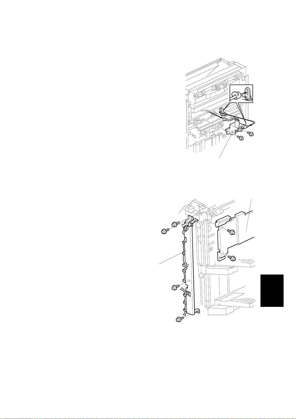
1.9 LOWER EXIT SENSOR
1. Front door, external and internal
covers. (☛ 1.1)
2. Exit guide plate motor (☛ 1.7)
3. Guide plate [A] (" x1)
Pull the shaft toward you through the
round hole.
[A]
B352R112.WMF
4. Guide plate exit assembly [B] (# x1,
" x1)
5. Anti-static brush [C] (! x2)
6. Bracket guide exit [D] (! x2)
7. Lower exit sensor [E] (! x1, # x1)
[B]
B352R113.WMF
[C]
[E]
Peripherals
[D]
B352R114.WMF
B352-7
Page 9

LOWER STACK HEIGHT SENSORS 26 January, 2001
1.10 LOWER STACK HEIGHT SENSORS
1. Stapler tray (☛ 1.5)
[B]
2. Sensor bracket [A] (! x1, # x2)
3. Bracket [B] (! x1)
4. Feeler [C]
5. Lower stack height sensors [D]
[C]
1.11 TRAY 2 SHUNT POSITION SENSOR
1. Stapler tray (☛ 1.5)
2. Sensor bracket [A] (! x1, # x1)
3. Tray 2 position shunt sensor [B] (! x1)
[B]
[A]
[D]
B352R116.WMF
[A]
B351R202.WMF
B352-8
Page 10
26 January, 2001 STAPLER UNIT
1.12 STAPLER UNIT
1. Open the front door
2. Stapler unit [A] (! x1, # x2)
Hold the stapler holder [B] with one
hand as you remove the
stapler. Do not twist or rotate
the stapler bracket as you
remove it.
[B]
1.13 STAPLER ROTATION HP SENSOR
1. Stapler unit (☛ 1.12)
2. Carefully rotate the stapler holder
[A].
3. Stapler cover [B] (! x1)
[A]
B352R117.WMF
[D]
[C]
4. Sensor bracket [C] (! x1, # x1)
5. Stapler rotation HP sensor [D]
[B]
[A]
B352R118.WMF
Peripherals
B352-9
Page 11
TRAY 1 INTERIOR 26 January, 2001
1.14 TRAY 1 INTERIOR
1.14.1 TRAY 1 COVERS
1. Tray 1 [A] (! x1)
2. Rear tray cover [B] (! x1)
3. Front tray cover [C] (! x1)
4. Bottom tray cover [D] (! x2)
5. Bottom bracket [E] (! x3)
[A]
[B]
[C]
[D]
B352R207.WMF
[E]
B352R208.WMF
B352-10
Page 12

26 January, 2001 TRAY 1 INTERIOR
1.14.2 TRAY SHIFT SENSORS AND TRAY RELEASE SENSOR
1. Tray 1 covers (☛ 1.14.1)
2. Gear disk [A] (" x1)
3. Tray shift sensors [B] (# x1 each).
4. Tray release sensor [C] (# x1)
1.14.3 TRAY 1 SHIFT MOTOR
1. Tray 1 covers (☛ 1.14.1)
2. Motor bracket [A] (! x3, # x1)
3. Tray 1 shift motor [B] (! x3, belt x1)
[B]
[B]
[C]
[A]
B352R210.WMF
[A]
1.14.4 BACK FENCE LOCK CLUTCH
1. Tray 1 covers (☛ 1.14.1)
2. Back fence lock clutch [A] (" x1, #
x1)
[A]
[B]
B352R209.WMF
Peripherals
B352R211.WMF
B352-11
Page 13

FINISHER MAIN BOARD 26 January, 2001
1.15 FINISHER MAIN BOARD
1. Rear cover (☛ 1.1.1)
2. Main PCB [A] (! x 6, All #)
[A]
B352R206.WMF
1.16 PUNCH HOLE POSITION ADJUSTMENT
To adjust the position of the punch holes in the paper feed direction, use the
appropriate SP mode.
To adjust the horizontal position of the holes, use the spacers provided with the
punch unit.
1. Rear cover (☛ 1.1.1)
2. Punch unit [A] (! x3, # x5)
3. Spacers [B]
The punch position can be
adjusted by up to 4 mm using
combinations of the 3 spacers
provided with the finisher.
B352-12
[A][B]
B352R119.WMF
Page 14

26 January, 2001 TIMING CHARTS
2. TROUBLESHOOTING
2.1 TIMING CHARTS
2.1.1 A4(S)/LT(S) SHIFT MODE WITH PUNCH – TRAY 1
500 ms
0 1000 2000 3000 4000 5000
Time (ms)
0 1579 3157
1
Finisher
→
Main Unit
01010
0
Feed-out ON
Shift ON
467 2046 3624
Feed-out OFF
34 pulse (700 ms)
ON
OFF
OFF
Tray 1 Shift Sensor
1250 ms
399 pulse (2 s)
<Jam Detection>
66 pulse (1353 ms)34 pulse (700 ms)
Peripherals
1166 1633 2645 3112 4223 4690
109 576 1688 2155 3266 3733
1
Stop
1
Main Unit
→
Finisher
0
Feed-out
Finisher
ON
OFF
Entrance Sensor
131 ms 155 ms
ON
OFFONOFFONOFF
Upper Exit Sensor
Entrance Motor
Low
OFF
ON
Exit Motor
OFF
Punch Motor
ON
Upper Transport Motor
ON
ON
OFF
Punch Clutch
ON
OFF
Punch H.P. Sensor
Tray 1 Shift Motor
B352D501.WMF
B352-13
Page 15

TIMING CHARTS 26 January, 2001
2.1.2 A4(S)/LT(S) SHIFT MODE WITH PUNCH – TRAY 2
500 ms
4200 4667
3266 3774
2633 3100
0 1000 2000 3000 4000 5000
Time (ms)
1579 3157
0
1
Finisher
→
Main Unit
0
01010
Feed-out ON
Shift ON
467 2046 3624
Feed-out OFF
1
Stop
1
Main Unit
→
Finisher
0
Feed-out
1688 2155
109 576
Finisher
1054 1521
ON
OFF
ON
OFFONOFFONOFF
Entrance Sensor
Lower Exit Sensor
155 ms
131 ms
Entrance Motor
Upper Transport Motor
ON
Low
OFF
ON
Exit Motor
ON
OFF
OFF
Punch Motor
Punch Clutch
ON
OFF
ON
OFF
Punch H.P. Sensor
Tray 2 Shift Motor
34 pulse (700 ms)
1250 ms
ON
OFF
399 pulse (2 s)
Tray 2 Shift Sensor
<Jam Detection>
B352D502.WMF
66 pulse (1353 ms)
34 pulse (700 ms)
B352-14
Page 16

26 January, 2001 TIMING CHARTS
2.1.3 A4(S)/LT(S) STAPLE MODE WITH PUNCH
13777
13036
87668816 15286
11353 12056
7765
7662 9241
6617 7320
6332 11068
5304 6039
484 pulse (1194 ms)
186 pulse (459 ms)
11545
11508
10904
10884
10434
10256
10406
10256
10228
10145
9825
9785
8893
8767
8827
8741
8246
8206
6814
6772
6168
5918
6148
5698
5520
5670
5437
5492
5089
5049 5409
4158
4032
435 pulse (1073 ms)
4092
4006
3511
3471
108846148
10303
10045 10228
9705
8281
8186
5567
5492
5309
5029
3546
3451
11689
11503
11575
11154
10904
10454
8300
6958
6767
6844
6148
6168
5718
250 ms
150 ms
1260 ms
0 2000 4000 6000 8000 10000 20000
Time (ms)
1579 3157 4736 6314 7893
0
0101010
Finisher
→
Feed-out ON
Staple ON
Main Unit
1
Feed-out OFF
2404
100 ms
2278
2338
2252
1932
ON
OFF
Punch Motor
120 ms
ON
OFF
Punch Clutch
1892
OFF
CW
CCW
Jogger Motor
OFF
CW
CCW
Stapler Motor
1525 1772 3104 3351 4682 4929 7839 8086 9418 9665
109 576 1688 2155 3266 3733 4845 5312 6423 6890 8002 8469
0
1
Main Unit
→
Stop
Feed-out
Finisher
Staple Done
ON
OFFONOFFONOFF
Entrance Sensor
Finisher
Staple Tray Entrance
Sensor
Staple Tray Paper
Sensor
131 ms 155 ms
ON
OFF
Lower Exit Sensor
1348 2927 4505
156 ms
(761 ms)
245 pulse
ON
ON
OFFONOFF
Upper Transport Motor
Lower Transport Motor
Pre-stack Motor
OFF
2152
100 ms
ON
OFF
ON
OFF
Pre-stack Gate Solenoid
Stapler Gate Solenoid
Positioning Roller
1872
ON
Solenoid
OFF
ON
OFFONOFF
Staple Hummer Motor
Staple Hummer H.P.
Sensor
OFF
OFF
CW
CCW
Stack Fee-out Motor
Stack Feed-out H.P.
Sensor
High
Low
OFF
Exit Motor
ON
OFF
Entrance Motor
34 pulse (839 ms) 34 pulse (839 ms) 600 ms 1500 ms
102 pulse (2516 ms)
Peripherals
2000 ms
<Jam Detection>
B352D503.WMF
B352-15
Page 17

JAM DETECTION 26 January, 2001
2.2 JAM DETECTION
Mode
Shift Staple
!!
!!
!
!
!
!
!
!
Jam Content
Entrance sensor:
On check
Entrance sensor:
Off check
Tray exit sensor:
On check
Tray exit sensor:
Off check
Stapler tray
entrance sensor:
On check
Stapler tray
entrance sensor:
Off check
Lower tray exit
sensor:
On check
Lower tray exit
sensor:
Off check
The entrance sensor does not t urn on w ithin
399 pulse after the main machine exit
sensor turns off.
The entrance sensor does not t urn of f within
34 pulse after it turns on.
*1
*1
The tray exit sensor does not turn on within
66 pulse after the entrance sensor turns o f f.
*1
The tray exit sensor does not turn off within
66 pulse after the tray exit sensor turns on.
The stapler tray entrance sensor d oes not
switch on within 102 pulses after the
entrance sensor switched off.*
1
The staple tray entrance sens or does not
turn off within 34 pulse after the stapler t ray
entrance sensor turns on.*
1
The lower exit sensor does not on w ithi n
1260 ms after the stack feed-out motor turns
on.
The lower exit sensor does not of f withi n
1500 ms after it turns on.
*1
Counted by entrance motor pulses because timing differs for feed out.
B352-16
Page 18

26 January, 2001 DIP SWITCH SETTINGS
3. SERVICE TABLES
3.1 DIP SWITCH SETTINGS
The DIP switches should not be set to any combination other than those described
in the table below.
DPS101
1234
0000Default.
1 1 1 0 Free run. No paper.
0 0 0 1 Factory shipping. See the note below.
Mode Description
To position the shift trays for shipping, on the finisher main board set DIP SW4 ON,
cycle the main machine power off and on, then set DIP SW4 OFF. The
shift trays move automatically to the shipping position. After unpacking the
machine again and switching on, turn all DIP switches off to put the
machine into factory default mode.
3.2 TEST POINTS
No. Label Monitored Sign al
TP101 GND Ground
TP102 5V 5V
TP103 RXD Received command data
TP104 TXD Transmitted command data
3.3 FUSES
No. Function
FU101 Protects 24 V.
B352-17
Peripherals
Page 19

GENERAL LAYOUT 26 January, 2001
4. DETAILED DESCRIPTIONS
4.1 GENERAL LAYOUT
1
8
2
3
7
4
6
5
B352D118.WMF
1 Upper junction gate 5 Stapler
2 Punch unit (option) 6 Stapler tray
3 Stapler junction gate 7 Tray 2
4 Pre-stack tray 8 Tray 1
Tray junction gate: Directs paper either to the upper or lower exit. In staple mode,
the stack always goes out to the lower exit.
Stapler junction gate: Directs paper either to the lower exit or to the stapler tray.
Pre-stack tray: When stapling multiple copies (A4 S, LT S, B5 S only) in the staple
mode, the first sheet of the second copy waits here for the next sheet to feed while
the previous stack is stapled. After the second copy is fed, the first and second
sheets are fed together to the pre-stack tray. This delay allows enough time for the
previous stack to be stapled without interrupting paper feed.
Shift trays: Tray 1 (upper) and tray 2 (lower) shift side to side in the sort mode,
and raise and lower to receive ejected copies.
Stapler tray jogger: Employs positioning rollers and jogger fences to align stacks
for stapling.
Punch unit. Punches holes in stacked copies.
B352-18
Page 20

26 January, 2001 DRIVE LAYOUT
4.2 DRIVE LAYOUT
4
3
2
14
13
12
11
10
1
5
6
15
7
16
9
8
B352D104.WMF
1. Tray 1 lift motor
2. Entrance roller
3. Tray 2 lift motor
4. Upper exit roller
5. Tray 1 shift motor
6. Exit guide plate motor
7. Lower exit roller
8. Tray 2 shift motor
9. Exit motor
18
10. Lower transport motor
11. Pre-stack motor
12. Upper transport motor
13. Punch motor
14. Entrance motor
15. Stack feed-out motor
16. Jogger motor
17. Stapler motor
18. Stapler rotation motor
17
B352D103.WMF
Peripherals
B352-19
Page 21

JUNCTION GATES 26 January, 2001
4.3 JUNCTION GATES
The two junction gates can direct paper to three destinations.
In sort/stack mode for tray 1, the tray junction
solenoid [A] is on, and the copies go to the upper exit
(tray 1 is at the upper exit for sort/stack mode).
In sort/stack mode for tray 2, both the tray junction
gate solenoid [A] and stapler junction gate solenoid
[B] are off, and copies go to the lower exit.
[A]
B302D506.WMF
[A]
In staple mode, the tray junction solenoid [A] is off and
the stapler junction gate solenoid [B] is on, and copies
go to the stapler tray.
[B]
B302D505.WMF
[A]
[B]
B302D507.WMF
B352-20
Page 22

26 January, 2001 TRAY SHIFTING
4.4 TRAY SHIFTING
4.4.1 TRAY SHIFT MECHANISMS
[F]
[A] [B]
[C]
[D]
[E]
B352D106.WMF
Tray 1 (Upper Tray)
In sort/stack mode, tray 1 [A] moves from side to side to separate the printed sets.
The tray 1 shift motor [B], inside the shift tray, controls the horizontal position of
tray 1 through the timing belt [C] and gear disk [D].
After one print set is delivered to tray 1, the shift motor turns on, driving the gear
disk and the arm [E], and the tray drive unit moves to one side.
Two shift sensors [F] detect when to stop this side-to-side movement. There is a
cut-out in the gear disk. The shift tray moves in one direction until one of the shift
sensors detects the cut-out. Then the shift tray stops.
The next set of prints is then delivered, and the gear disk is turned in the opposite
direction until the other shift sensor is activated.
Peripherals
B352-21
Page 23

TRAY SHIFTING 26 January, 2001
Tray 2 (Lower Tray)
[C]
[A]
[E]
[D]
[B]
B352D105.WMF
In sort/stack mode, tray 2 [A] moves from side to side to separate the sets of prints.
The shift mechanism for tray 2 is similar to that used for tray 1. However, when the
tray 2 shift motor [B] turns on, the arm [D] moves the entire end fence [C] from side
to side (not just the tray).
After the gear disk has turned 180 degrees, the cut-out in the gear disk enters the
tray half- turn sensor [E], and the motor stops . When the next set of prints is
delivered, the motor turns on again, and moves the tray back to its previous
position.
B352-22
Page 24

26 January, 2001 TRAY UP/DOWN MECHANISMS
4.5 TRAY UP/DOWN MECHANISMS
4.5.1 TRAY 1
[H]
[A]
[C]
[F]
[G]
Introduction
[I]
[E]
[D]
[C]
[B]
B352D204.WMF
The tray 1 lift motor [A] controls the vertical position of tray 1 [B] through gears and
timing belts [C].
Normal and sort/stack modes
When the ma in s witch is turned on, the tr ay is initialized at the upper position. To
do this, the tray is moved up until upper stack height sensor 1 [D] is de-actuated.
During printing, if upper stack height sensor 2 [E] is actuated, the tray 1 lift motor
lowers the tray for a specified time.
When the tray lowers during printing, th e actuator [F] will pass through the tray 1
overflow sensor [G]. When the actuator drops below the sensor (to deactivate the
sensor), the machine detects that the paper stack height has exceeded a certain
limit.
The upper limit switch for tray 1 [H] prevents the drive gear from being damaged if
the upper stack height sensor 1 should fail. If the tray is raised to the tray
positioning roller [I], the switch will automatically cut the power to the tray 1 lift
motor.
Peripherals
B352-23
Page 25

TRAY UP/DOWN MECHANISMS 26 January, 2001
Staple mode
[A]
[B]
[D] [E]
[G]
[C]
[F]
B352D204.WMF
In staple mode, stapled stacks can be delivered to either tray, but they can only go
to the lower exit. So, if tray 1 is selected, tray 1 [A] moves down to the lower paper
exit.
Tray 1 lowers until the actuator [B] enters the tray 1 lower limit sensor [C]. Tray 1
then lifts up until lower stack height sensor 1 [D] is activated.
When tray 1 is moved down to the lower exit, tray 2 must be moved down out of
the way. So, tray 2 [E] is also lowered until the tray 2 shunt position sensor [F]
detects tray 2 (or the top of the paper stack in tray 2).
The method of paper height detection is the same as for the upper exit area.
When the tray lowers during printing, t he actuator will enter the tray 1 overflow 2
sensor [G]. When this happens, the machine detects that the paper stack height
has exceeded the overflow limit.
B352-24
Page 26

26 January, 2001 TRAY UP/DOWN MECHANISMS
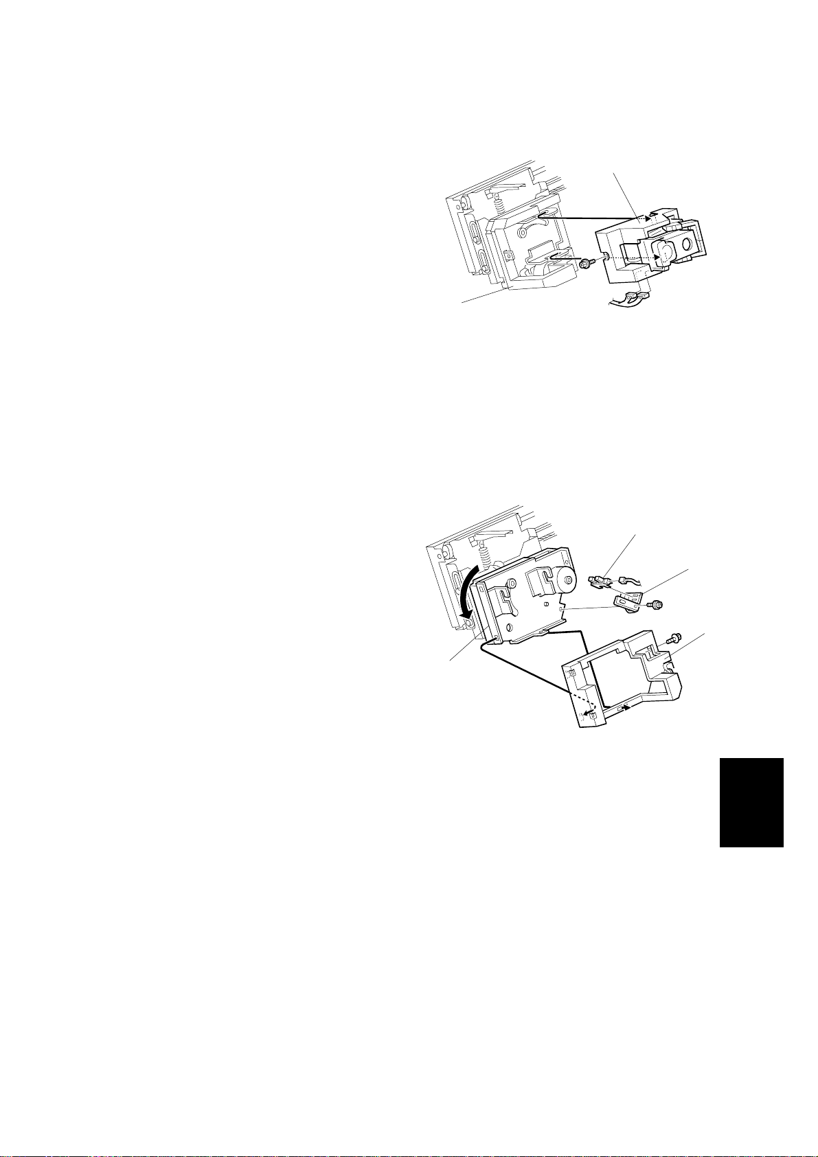
Tray 1 release mechanism
When tray 1 is selected for staple mode,
tray 1 must be moved down to the lower
paper exit. However, to move past the
sensors at the lower exit, the tray must be
moved away from the finisher.
To do this, the tray 1 shift motor turns until
the cut-out in the gear disk enters the tray
release sensor [A]. At this time, the arm [B]
has reached position [C], and is pushing
against the plate [D], in towards the
finisher. However, the plate is fixed, so the
tray moves out away from the finisher.
Then, the tray 1 shift motor stops, then the
tray 1 lift motor lowers tray 1.
When the tray 1 lower limit sensor is
activated (as described on the previous
page), the tray has moved past the
sensors at the lower exit. The tray 1 shift
motor turns on again until the gear disk
activates the tray shift sensor [E]. This
moves the tray back against the finisher.
[A]
[D]
[B]
[C]
B352D201.WMF
[E]
Next, tray 1 lifts until the finisher detects
that the tray is at the correct height.
B352D202.WMF
Peripherals
B352-25
Page 27

TRAY UP/DOWN MECHANISMS 26 January, 2001
When tray 1 is at the lower exit, the tray
lock solenoid [F] is on, and the lever [G]
locks the tray. This prevents the user from
[I]
[F]
moving the tray out of position (the first
tray has some play when it is at the lower
position).
Before tray 1 goes back to the upper exit
area, the tray lock solenoid [F] turns off to
unlock the tray. In addition, the back fence
lock clutch [H] turns on to hold the back
fence [I]. This prevents the springs inside
[H]
the back fence from suddenly contracting
(these springs normally keep the tray
steady during side-to-side shift).
B352D203.WMF
Then, tray 1 is released and it moves up to
the upper exit area.
[G]
B352-26
Page 28

26 January, 2001 TRAY UP/DOWN MECHANISMS
4.5.2 TRAY 2
[H]
[A]
Overflow condition
[B]
[D]
[C]
[F]
[E]
[D]
[C]
[F]
Normal ModeMulti Tray Staple Mode
B352D500.WMF
[G]
B352D109.WMF
The tray 2 lift motor [A] controls the vertical position of tray 2 [B] through gears and
timing belts [C].
The paper height detection is the same as for tray 1.
When the tray lowers during printing, the tray is judged to be overflowing when the
tray 2 overflow sensor 1 [D] is off and the tray 2 overflow sensor-2 [F] is on (see
‘Normal Mode’ in the above diagram).
[E]
In the multi-tray staple mode (selected by the service technician), the machine
detects that the paper stack height has exceeded the overflow limit when the
actuator [E] enters the tray 2 overflow 1 sensor [D].
The lower limit sensor [G] for tray 2 detects when tray 2 is at its lowest limit and
stops the tray 2 lift motor.
The function of the tray 2 upper limit switch [H] is the same as for tray 1.
B352-27
Peripherals
Page 29

TRAY UP/DOWN MECHANISMS 26 January, 2001
4.5.3 PRE-STACK MECHANISM
[B]
[A]
[C]
[D]
00MTY.WMF
This feature is available only when using A4 L, LT L, and B5 L.
During stapling, the main machine must wait. This mechanism reduces the wait by
holding the first two sheets of a job while the previous job is still being stapled. It
only works during the second and subsequent sets of a multi-set print job.
The pre-stack junction gate solenoid [A] switches on after the first sheet activates
the entrance sensor. This directs the sheet to the pre-stack tray [B].
The pre-stack feed roller [C] stops for a specifie d time after the trailing edge of the
paper has passed through the entrance sensor and stops the paper from leaving
the pre-stack tray.
At the same time, the pre-stack junction gate solenoid switches off, and the second
sheet is sent to the paper guide [D]. The pre-stack feed roller (controlled by the
pre-stack motor) starts to rotate again for a specified time after the trailing edge of
the second page has been passed through the entrance sensor, and then both
sheets are sent to the stapler tray together.
B352-28
Page 30

26 January, 2001 JOG GER UNIT PAPER POSITIONING MECHANISM
4.6 JOGGER UNIT PAPER POSITIONING MECHANISM
[C]
[E]
[A]
[B]
[F]
[D]
B352D110.WMF
In staple mode, each sheet of copy paper is vertically and horizontally aligned
when it arrives in the stapler tray.
Vertical Paper Alignment
After the trailing edge of the paper passes the stapler tray entrance sensor [A], the
positioning roller solenoid [B] is energized for a specified time to push the
positioning roller [C] into contact with the paper.
The positioning roller rotates to push the paper back and align the trailing edge of
the paper against the stack stopper [D].
Horizontal Paper Alignment
When the start key is pressed , the jogger motor [E] turns on and the jogger fences
[F] move to the waiting position, which is 8 mm wider on both sides than the
selected paper.
When the trailing edge of the paper passes the stapler tra y e ntrance sensor, the
jogger motor turns on to move the jogger fences 5 mm towards the paper. After a
short time, the jogger motor turns on again for the horizontal paper alignment then
returns to the waiting position.
B352-29
Peripherals
Page 31

STAPLER MECHANISM 26 January, 2001
4.7 STAPLER MECHANISM
4.7.1 STAPLER MOVEMENT
[D]
[B]
[A]
[B][E]
B352D112.WMF
[C]
B352D113.WMF
The stapler can be moved from side to side or rotated according to the
requirements of the selected stapling mode.
Stapler Rotation
After the start key is pressed, the stapler rotation motor [A] rotates the staple unit
[B] until the stapler rotation HP sensor [C] is activated. Then, the stapler moves
from front to rear of the finisher.
When oblique stapling at one pos ition has been selected, after the stapler moves
to the stapling position, the stapler rotation motor rotates the stapler 45 degrees
(clockwise) at the stapling positio n before the stapler fires.
Side-to-Side Movement
The stapler motor [D] moves the stapler from side to side. After the start key is
pressed, the stapler moves from its home position to the stapling position.
The amount of movement required to reach the stapling position is determined by
the size of the selected paper. If the two-staple mode is selected, the stapler
moves to the front stapling position first, and then moves to the rear stapling
position. However, for the next print set, it staples in the reverse order.
After the stapling job is finished, the stapler returns to its home position,
determined by the stapler HP sensor [E].
B352-30
Page 32

26 January, 2001 STAPLER MECHANISM
4.7.2 STAPLER
[D]
[B]
[C]
B352D208.WMF
[A]
The staple hammer is driven by the stapler hammer motor [A] inside the stapler.
As soon as the paper stack is aligned, the staple hammer motor starts. When
stapling is finished, the staple hammer HP sensor [B] is turned on, and the staple
hammer motor then stops.
The staple end sensor [C] detects the staple end condition and whether the staple
cartridge is installed or not. If a stapler cassette is not installed, or after the stapler
cassette runs out of staples, a message is displayed in the operation panel. If this
condition is detected during a print job, the indicator will appear, but the print job
will not stop.
The staple position sensor [D] detects if there is a staple sheet at the stapling
position. After a new staple cartridge is installed, the staple hammer motor turns on
to transfer the staple sheet until the staple position sensor is activated by the staple
sheet.
If a staple jam occurs and overloads the motor, this causes a staple jam message
to appear on the operation panel.
Peripherals
B352-31
Page 33

STAPLER MECHANISM 26 January, 2001
4.7.3 FEED OUT AND TRANSPORT
[A]
[C]
[I]
[B]
B352D115.WMF
[D]
[G]
[F]
[H]
B352D114.WMF
When stapling starts, the exit guid e plate motor [A] switches on and opens the exit
guide plate [B], so that the stapled stack can exit to the tray. The exit guide plate
sensor [C] detects when to switch off the exit guide plate motor.
After the prints have been stapled, the stack feed-out motor [D] starts. The pawl [E]
on the stack feed out belt [F] lifts the stapled set and feeds it to the tray [G].
The exit guide plate closes at a specified interval after the stapled prints have
started to feed out. Then the exit roller takes over the stack feed-out. The stack
feed-out motor turns off when the pawl actuates the stack feed-out belt home
position sensor [H].
[E]
When tray 1 is passing this area on its way back up to the upper exit, the exit guide
safety switch [I] cuts power to the tray lift motor if the guide is opened too far. This
prevents damage to the user’s fingers if they are inside the lower exit when the tray
is moving up.
B352-32
Page 34

26 January, 2001 PUNCH UNIT (OPTIONAL)
4.8 PUNCH UNIT (OPTIONAL)
The punch unit punches holes in printed sheets, one by one. The punch unit is
provided with a new punch mechanism to improve the accuracy of punching.
[A]
[E]
[D]
[C]
[B]
B352D116.WMF
[I]
B377D101.WMF
[F]
4.8.1 PUNCH DRIVE MECHANISM
The punch drive mechanism is driven by the punch motor [A]. Each sheet is
positioned and punched by pressure from above. A certain time after the trailing
edge of the paper passes through the finisher entrance sensor [B], the punch
motor turns on and the paper stops. Then the punch clutch [C] turns on to make
the punch holes.
[H]
[G]
Peripherals
The home position is detected by the punch HP sensor [D]. When the cut-out in the
punch shaft disk [E] enters the punch HP sensor, the punch clutch turns off.
When the finisher has received the command that changes the number of punch
holes, the punch hole motor [F] turns on until the disk changes the status of the
punch hole switch [G] (until it switches on or off). This indicates that the cover [H]
and the punch cam [I] have moved to one side or the other to change the number
of holes.
B352-33
Page 35

PUNCH UNIT (OPTIONAL) 26 January, 2001
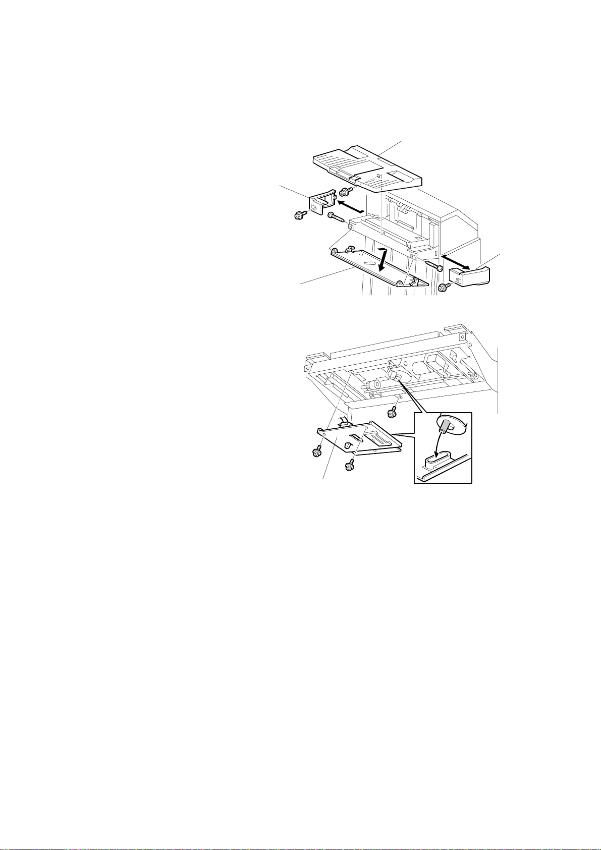
4.8.2 PUNCH WASTE COLLECTION
[A]
[B]
[C]
B352D117.WMF
Waste punchouts are collected in the punch waste hopper [A] below the punch unit
inside the finisher.
When the top of the punchout waste in the hopper reaches and actuates the
hopper sensor [B], a message will be displayed on the operation panel after the
current job is completed.
This sensor also detects whether the punch waste hopper is installed. When the
waste hopper is taken out, the arm [C] moves down and this will actuate the sensor
and display a message in the operation panel. This message is the same as for the
hopper full condition.
B352-34
 Loading...