

Page 1

BOOKLET FINISHER
(Machine Code: A763)
Page 2

TABLE OF CONTENTS
1. OVERALL MACH INE INFORMATION..................................A763-1
1.1 SPECIFICATIONS..............................................................................A763-1
1.2 ELECTRICAL COMPONENT DESCRIPTION....................................A763-3
1.3 MECHANICAL COMPONENT LAYOUT.............................................A763-6
2. DETAILED DESCRIPTIONS .................................................A763-7
2.1 JUNCTION GATE MECHANISM........................................................A763-7
2.1.1 SHIFT TRAY MODE..................................................................A763-7
A4/LT sideways or shorter.............................................................A763-7
Longer than A4 sideways...............................................................A763-7
2.1.2 PROOF TRAY MODE ................................................................ A763-8
2.1.3 BOOKLET STITCH MODE........................................................A763-8
2.2 PRE-STACK MECHANISM ................................................................A763-9
2.3 PAPER SHIFT MECHANISM ...........................................................A763-10
2.4 PAPER POSITIONING MECHANISM..............................................A763-11
2.5 STAPLER UNIT MOVEMENT MECHANISM....................................A763-12
2.5.1 DRIVE......................................................................................A763-12
2.5.2 MOVEMENT............................................................................A763-12
Front and Rear Stapling...............................................................A763-12
Tow-position Stapling...................................................................A763-12
2.6 STAPLER .........................................................................................A763-13
2.7 SHIFT TRAY MECHANISM..............................................................A763-14
2.8 BOOKLET UNIT GATE MECHANISM..............................................A763-15
2.9 RELAY ROLLER AND POSITIONING PLATE MECHANISM...........A763-17
2.10 POSITIONING ROLLER MECHANISM..........................................A763-18
2.11 BOOKLET UNIT JOGGER MOVEMENT MECHANISM.................A763-19
2.12 BOOKLET STAPLER UNIT............................................................A763-20
2.13 PAPER FOLDER MECHANISM.....................................................A763-21
3. INSTALLA T ION...................................................................A763-23
3.1 ACCESSORY CHECK.....................................................................A763-23
3.2 INSTALLATION PROCEDURE ....................................................... A763-24
4. REPLACEMENT AND ADJUSTMENT................................A763-29
4.1 REMOVAL........................................................................................A763-29
4.1.1 UPPER DOOR.........................................................................A763-29
4.1.2 UPPER REAR COVER............................................................A763-30
4.1.3 LOWER REAR COVER...........................................................A763-30
4.1.4 TOP COVER............................................................................A763-31
4.1.5 UPPER INNER COVER...........................................................A763-31
4.1.6 SHIFT TRAY UNIT...................................................................A763-32
4.1.7 UPPER SHIFT GUIDE.............................................................A763-33
4.1.8 LOWER SHIFT GUIDE............................................................A763-33
4.1.9 EXIT UNIT................................................................................A763-34
i
Page 3

SPECIFICATIONS 31 January 2000
4.1.10 BUFFER ROLLER UNIT........................................................A763-35
4.1.11 STAPLER...............................................................................A763-36
4.1.12 FINISHER BOARD ...............................................................A763-37
4.1.13 BOOKLET UNIT.....................................................................A763-38
4.1.14 FOLDER ROLLERS...............................................................A763-40
4.1.15 FOLDER PLATE....................................................................A763-43
Removal.......................................................................................A763-43
Reinstalling...................................................................................A763-44
4.1.16 BOOKLET STAPLER UNIT...................................................A763-45
Removal.......................................................................................A763-45
Adjustment...................................................................................A763-46
4.1.17 BOOKLET BOARD................................................................A763-48
4.1.18 POSITIONING PLATE UNIT..................................................A763-48
4.1.19 1ST AND 2ND BOOKLET UNIT GATES ...............................A763-49
4.2 ADJUSTMENT..................................................................................A763-50
4.2.1 SHIFT TRAY HEIGHT .............................................................A763-50
4.2.2 JOGGER FENCE POSITION...................................................A763-51
4.2.3 STAPLING POSITOIN.............................................................A763-52
4.2.4 BOOKLET STAPLING POSITION...........................................A763-53
ii
Page 4
January 31, 2000 SPECIFICATIONS
1. OVERALL MACHINE INFORMATION
1.1 SPECIFICATIONS
Paper Size:
Tray Modes Sizes
Proof tray A3 to A5, DLT to HLT
No staple mode A3 to A5, DLT to HLT
Paper Weight:
Staple
Shift tray
Booklet tray A3 to B5, DLT to LT
Tray Weight
Stack mode 52 g/m2 to 163 g/m2, 14 to 42 lb
Staple mode 64 g/m2 to 80 g/m2, 17 to 21 lb
Saddle stitch mode 64 g/m2 to 80 g/m2, 17 to 21 lb
Mode
Top or
bottom
2 staple
64 g/m
only)
A3 to B5 lengthwise, DLT to HLT
A3, A4 sideways, B5 sideways,
DLT to HLT sideways
2
to 128 g/m2, 17 to 34 lb (Cover sheet
Paper Capacity (80 g/m2, 20 lb):
Tray Modes Paper size Capacity
Proof tray
No staple
Shift tray
Staple
tray
One size
Mixed sizes
Staple Capacity (80 g/m2, 20 lb):
Modes Paper size Total capacity
Staple
Saddle stitch 2-15 sheets
A4-S, LT-S or shorter 2-50 sheets
A4-L, LT-L or longer 2-30 s heets
Staple
A4-S, LT-S or shorter 150 sheets
A4-L, LT-L or longer 75 sheets
A4-S, LT-S or shorter 1000 sheets
A4-L, LT-L or longer 500 sheet
A4-S, LT-S or shorter 750 sheets
A4-L, LT-L or longer 500 sheets
1-5 sheets 25 sets
6-10 sheets 15 sets
11-15 sheets 10 sets
(-L”: Lengthwise ,-S: Sideways)
Options
(-L”: Lengthwise, -S: Sideways)
A763-1
Page 5

SPECIFICATIONS January 31, 2000
Staple Position: Staple mode: 3 positions
1 staple: 2 positions (Front, Rear)
2 staples: 1 position
Saddle stitch mode: 1 position
Staple Replenishment: Cartridge
Staple: 5000 staples
Saddle stitch: 2000 staples
Power Source: 24Vdc (from copier)
Power Consumption: 60 W
Dimensions
800 x 728 x 980 mm, 31.5 x 28.7 x 38.6 inches
(W x D x H) :
Weight: 45 kg
A763-2
Page 6

January 31, 2000 ELECTRICAL COMPONENT DESCRIPTION
1.2 ELECTRICAL COMPONENT DESCRIPTION
Symbol Name Function
Motors
M1 Entrance Drives the entrance roller.
M2 Transport Roller Drives the 1st and 2nd transport rollers.
M3 Buffer Roller Drives the buffer roller and the proof tray exit roller.
M4 Jogger Moves the jogger fence.
M5 Stapler Moves the stapler unit.
M6 Staple Hammer Drives the staple hammer in the stapler unit.
M7 Guide Plate Moves the upper exit guide plate up and down.
M8 Exit Motor Drives the exit roller.
M9 Tray Lift Moves the shift tray up and down.
M10 Booklet Transport Drives the relay roller and the positioning roller.
M11 Positioning Plate Moves the positioning plate up and down.
M12 Shutter Guide Moves the shutter guide up and down.
M13 Booklet Jogger Drives the jogger fences.
M14 Front Stapler Drives the staple hammer in the front stapler.
M15 Rear Stapler Drives the staple hammer in the rear stapler.
M16 Folder Roller Drives the folder rollers.
M17 Folder Plate Moves the folder plate.
Sensors
S1
S2
S3
S4 Staple Tray Paper Detects copy paper in the stapler tray.
S5 Jogger HP Detects the home position of the jogger rear fence.
S6 Stapler Unit HP Detects the home position of the stapler unit.
S7 Staple Hammer HP Detects the home position of the staple hammer.
S8 Staple Position Detects when the stapler is in the stapling position.
S9 Upper Exit Guide Detects the upper position of the upper exit guide.
S10 Exit Guide Motor Generates pulses to check the exit guide motor.
S11 Exit Checks for misfeeds at the shift tray.
S12 Exit Motor Generates pulses to check the exit motor.
S13 Shift Tray Paper Detects copy paper on the shift tray.
S14
S15 Shift Tray HP Detects the home position of the shift tray.
S16
S17
Entrance Detects copy paper entering the finisher and
detects misfeeds.
Buffer Roller
Entrance
Straight Path Detects copy paper passig under the buffer roller
Shift Tray height Detects when the top of the copy paper stack in the
Lift Motor 1 Generates pulses to check the lift motor, to control
Lift Motor 2 Generates pulses to check the lift motor, to control
Detects copy paper entering the buffer roller or
proof tray exit guide and detects misfeeds.
and detects misfeeds.
shift tray is at the correct height.
lift motor position, and to detect the motion
direction of shift tray.
lift motor position, and to detect the motion
direction of shift tray.
Options
A763-3
Page 7

ELECTRICAL COMPONENT DESCRIPTION January 31, 2000
Symbol Name Function
S18 Proof Tray Exit Checks for misfeeds at the proof tray.
S19
S20
Proof Tray Limit Detects when the paper stack height in the proof
tray is at its upper limit.
Finisher Set
Detects whether the finisher is installed into the
copier or not.
S21 Shutter Detects whether the shutter is closed or not.
S22 Trailing Edge 1 Detects the relay roller release timing.
S23 Trailing Edge 2 Detects the relay roller release timing.
S24 Trailing Edge 3 Detects the relay roller release timing.
S25 Booklet Entrance Check for paper misfeeds.
S26
S27
S28
S29
Positioning Plate
Paper
Positioning Plate
HP
Positioning Roller
Booklet Jogger HP
Detects copy paper in the positioning plate.
Detects the home position of the positioning plate.
Detects whether the positioning roller is released or
not.
Detects the home position of the jogger fences in
the booklet unit.
S30 Front Staple End Detects staples in the cartridge of the front stapler.
S31 Rear Staple End Detects staples in the cartridge of the rear stapler.
S32 Stapler Unit Set Detects whether the stapler unit is installed or not.
S33 Shutter Guide HP Detects the home position of the shutter guide.
S34 Folder Plate HP Detects the home position of the folder plate.
S35 Folder Plate Return Detects the return position of the folder plate.
S36
S37
Folder Plate Motor Generates pulses to check the folder motor and its
position.
Folder Roller
Detects the position of the folder roller.
Position
S38 Folder Roller HP Detects the home position of the folder roller.
S39
Folder Roller Motor Generates pulses to check the folder roller motor
and its position.
S40 Booklet Exit Checks for misfeeds at the booklet tray.
S41 Booklet Tray Paper Detects copy paper in the booklet tray.
S42
Booklet Entrance
Guide
Detects whether the booklet entrance guide is
opened or not.
S43 Lower Door Detects whether the lower door is opened or not.
S44
Booklet Exit Cover Detects whether the booklet exit cover is opened or
not.
Switches
SW1
Upper Cover
Safety
Cuts the +24V for the motor.
SW2 Shift Tray Safety Cuts the +24V for the motor.
SW3 Shutter Position Cuts the +24V for the motor.
SW4 Upper Exit Guide 1 Cuts the +24V for the motor.
SW5 Upper Exit Guide 2 Cuts the +24V for the motor.
SW6
Shift Tray Upper
Limit
Cuts the +24V for the lift motor.
A763-4
Page 8

January 31, 2000 ELECTRICAL COMPONENT DESCRIPTION
Symbol Name Function
SW7 Cartridge Set Detects the staple cartridge in the stapler.
SW8 Staple End Detects the staples in the cartridge.
SW9 Thermo Detects the lift motor temperature.
SW10 Lower Door Safety Cuts the +24V for the motor.
SW11
Booklet Entrance
Guide Safety
Cuts the +24V for the motor.
SW12 Booklet Exit Safety Cuts the +24V for the motor.
SW13
SW14
Front Staple
Hammer HP
Rear Staple
Hammer HP
Detects the home position of the staple hammer in
the front stapler unit
Detects the home position of the staple hammer in
the rear stapler unit
Solenoids
SOL1 Book let Gate Drives the booklet gate.
SOL2
Buffer Roller
Entrance Gate
Drives the buffer roller entrance gate.
SOL3 Proof Tray Gate Drives the proof tray gate.
SOL4
Buffer Roller Exit
Gate
Drives the buffer roller exit gate.
SOL5 Tr ansport Belt Moves the transport belt to the stopper.
SOL6 Paddle Releases the paddle stopper.
SOL7
SOL8
SOL3
Front Guide
Release
1st Booklet Unit
Gate
2nd Booklet Unit
Gate
Releases the front guide plate.
Drives the 1st booklet unit gate.
Drives the 2nd booklet unit gate.
SOL4 Relay Roller Releases the relay roller.
PCBs
PCB1 Finisher Controls the upper unit.
Lift Motor Sensor Generates pulses to check the lift motor, to control
PCB2
lift motor position, and to detect the motion
direction of the shift tray.
PCB3 Booklet Unit Controls the booklet unit.
PCB4
Trailing Edge
Sensor
Detects the relay roller release timing.
Others
HR1 Stapler Interface Interfaces the stapler and the finisher board.
A763-5
Options
Page 9
January 31, 2000 MECHANICAL COMPONENT LAYOUT
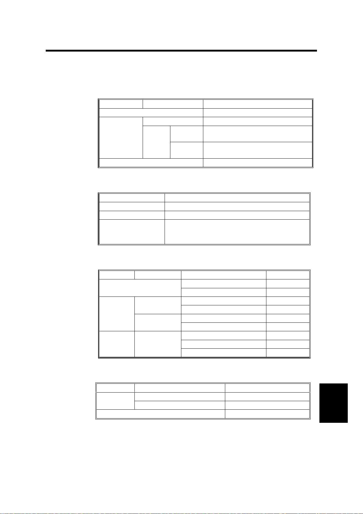
1.3 MECHANICAL COMPONENT LAYOUT
6
5
7
8
4
9
3
27
15
16
10
11
2
12
1
13
24
23
25
26
17
18
19
20
21
14
A763V500.WMF
A763V501.WMF
22
1. Shutter
2. Shift Tray
3. Lower Exit Roller
4. Upper Exit Guide
5. 2nd Transport Roller
6. Proof Tray
7. Buffer Roller Exit Gate
8. Buffer Roller
9. Proof Tray Gate
10. Buffer Roller Entrance Gate
11. Booklet Gate
12. 1st Transport Roller
13. Stapler Unit
14. Transport Belt
15. Booklet Unit Entrance Roller
16. 1st Booklet Unit Gate
17. 2nd Booklet Unit Gate
18. Anvil
19. Folder Plate
20. Positioning Plate
21. Shutter Guide
22. Booklet Tray
23. Exit Guide
24. Positioning Roller
25. Folder Roller
26. Relay Roller
27. Booklet Stapler Unit
Options
A763-7
Page 10
January 31, 2000 JUNCTION GATE MECHANISM
2. DETAILED DESCRIPTIONS
2.1 JUNCTION GATE MECHANISM
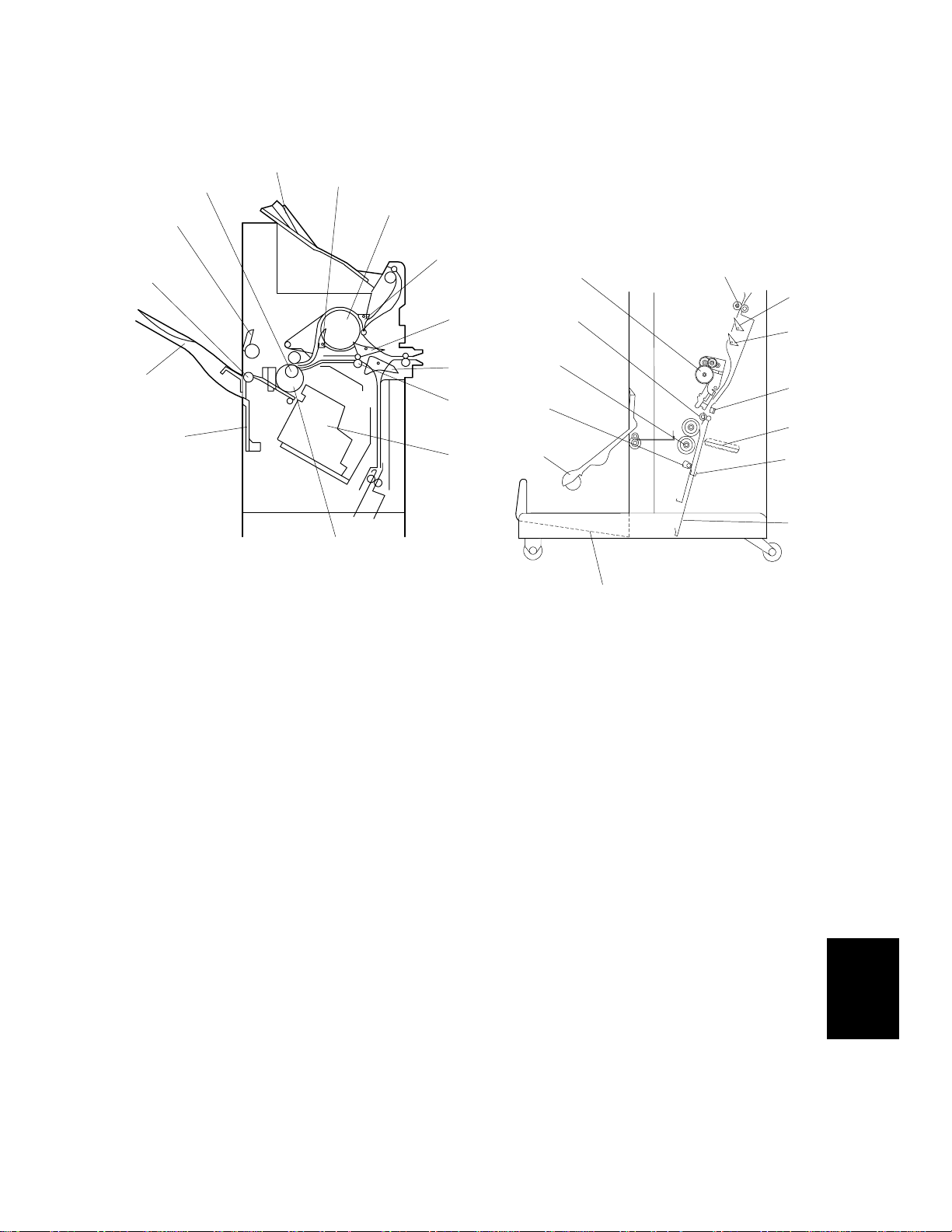
2.1.1 SHIFT TRAY MODE
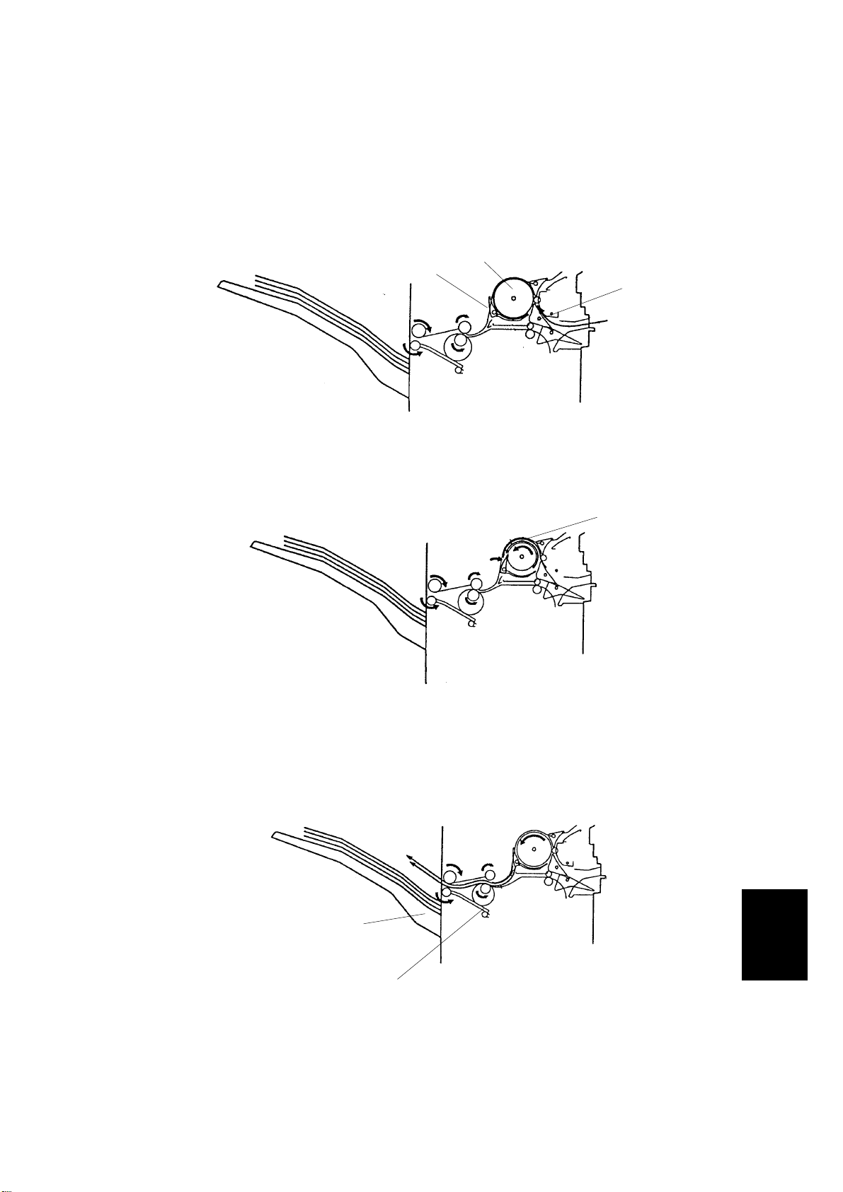
A4/LT sideways or shorter
[B]
[C]
A763D564.PCX
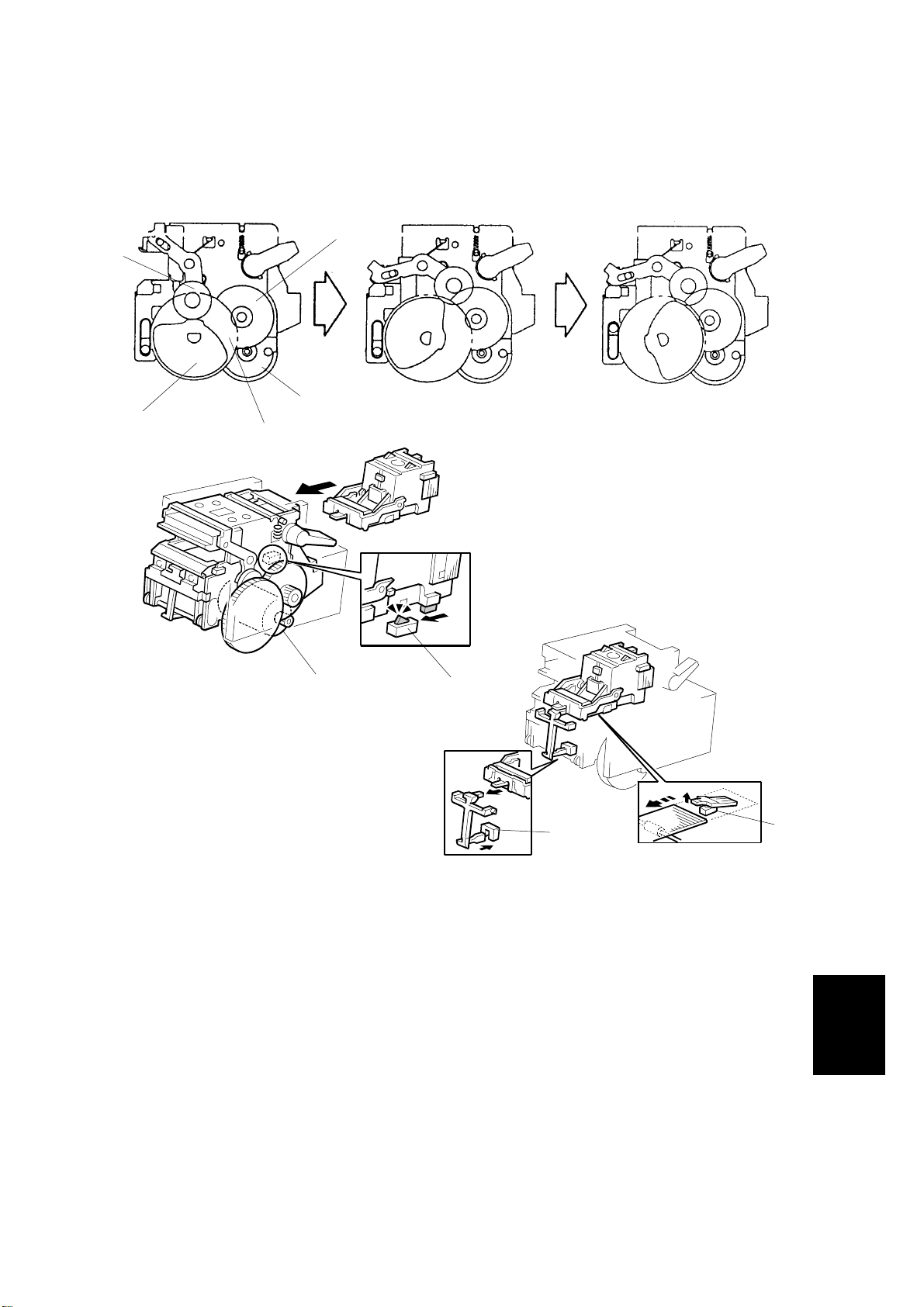
The booklet gate [A] and buffer roller entrance gate [B] are closed and the copy
paper goes directly to the shift tray [C].
[A]
Longer than A4 sideways
[F]
[E]
[D]
A763D565.PCX
The booklet gate, proof tray gate [D], and buffer roller exit gate [E] are closed, and
the buffer roller entrance gate is opened. The copy paper passes through the
buffer roller [F]. This paper path creates a distance between copies.
A763-7
Options
Page 11
JUNCTION GATE MECHANISM January 31, 2000
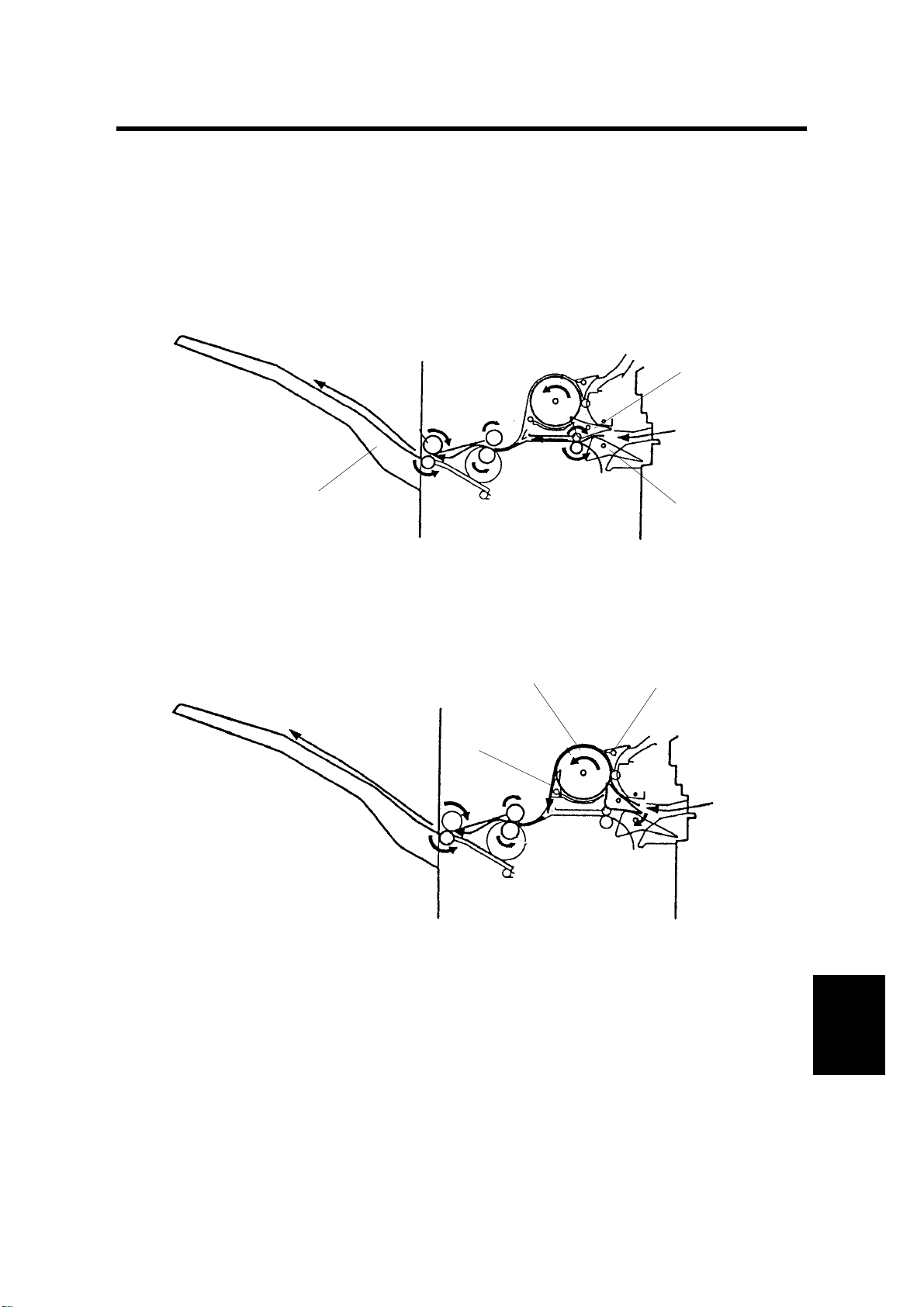
2.1.2 PROOF TRAY MODE
[D]
The booklet gate [A] is closed. The buffer roller
entrance gate [B] and proof tray gate [C] are
closed. The copy paper goes to the proof tray [D].
[C]
[B]
2.1.3 BOOKLET STITCH MODE
The booklet gate is opened and the copy paper
goes to the booklet unit.
[A]
A763D101.WMF
A763-8
A763D102.WMF
Page 12
January 31, 2000 PRE-STACK MECHANISM
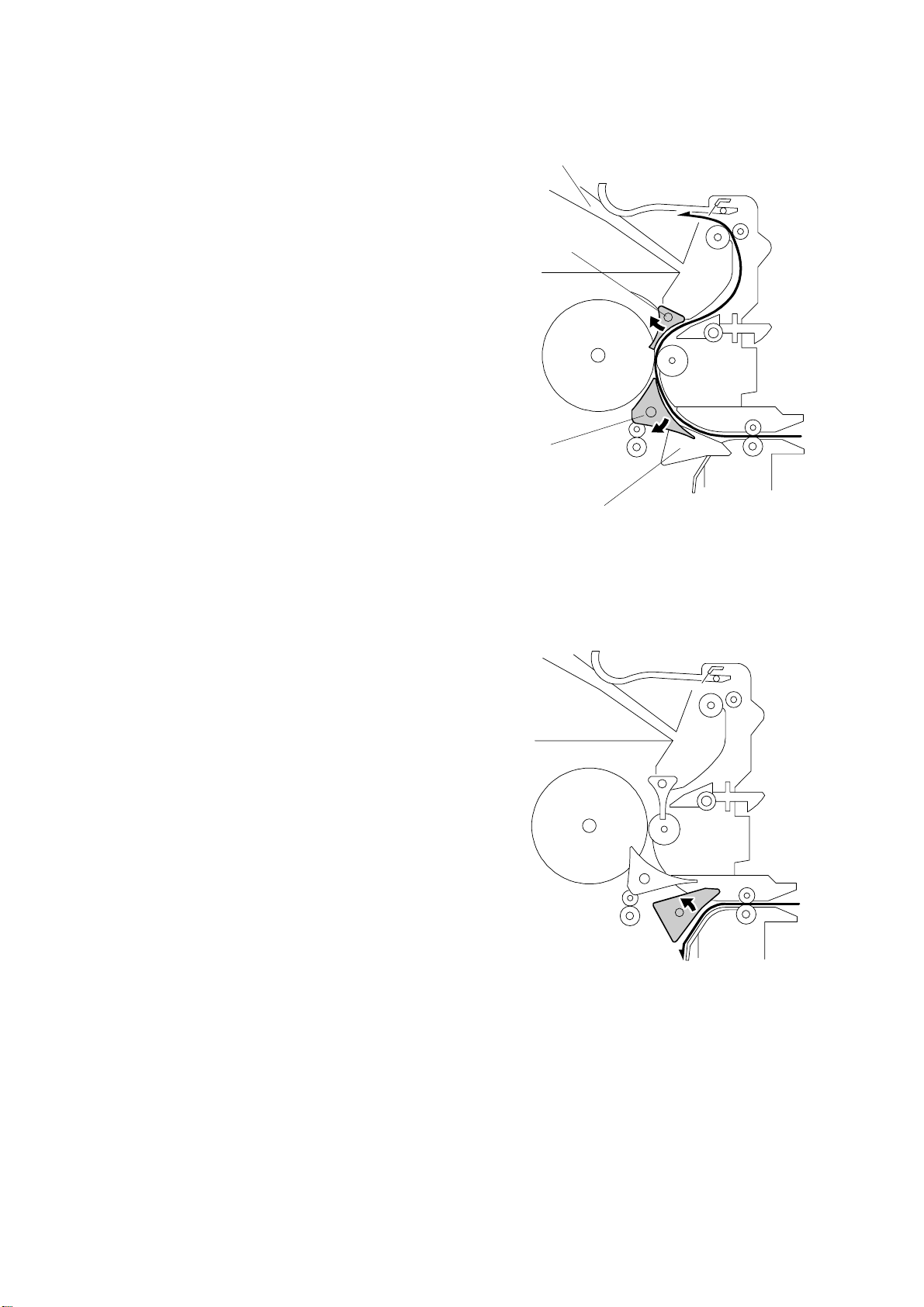
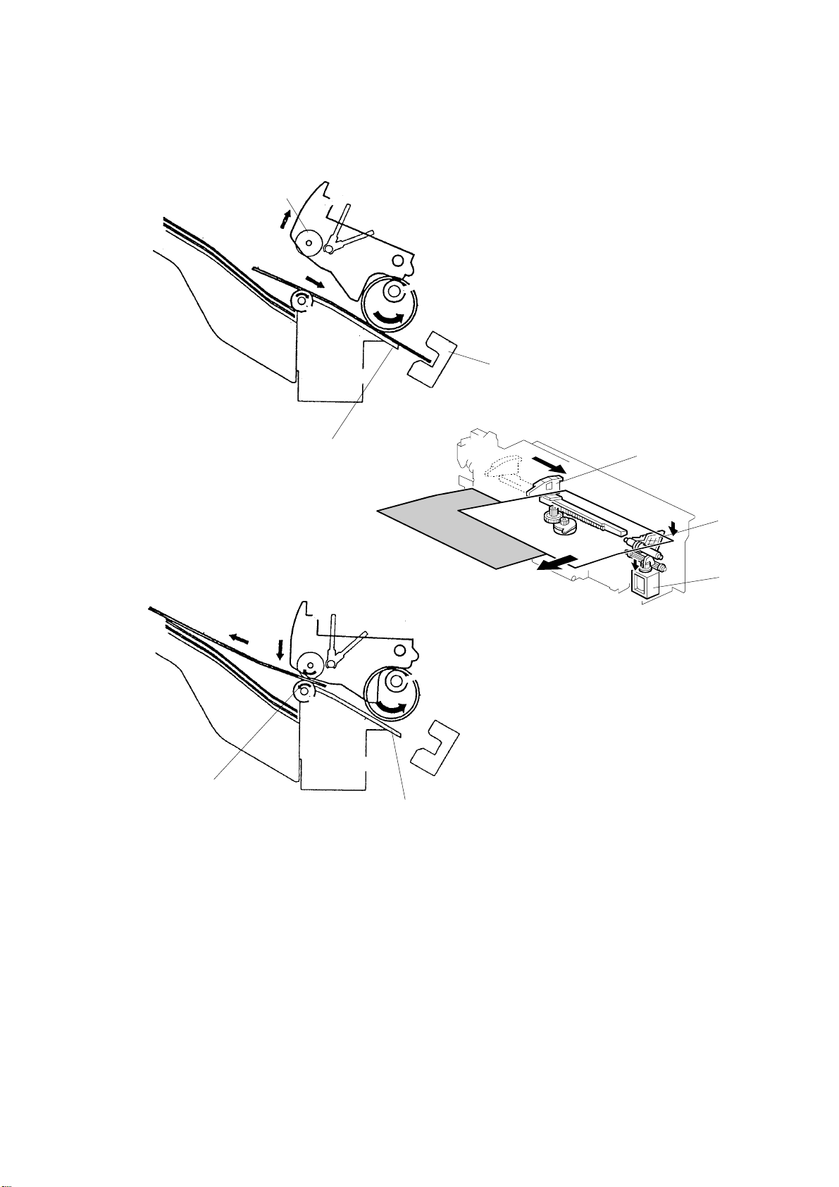
2.2 PRE-STACK MECHANISM
This mechanism improves productivity in staple mode and shift mode.
During stapling, the copier has to wait. This mechanism reduces the wait by
holding the first two sheets of a job while the previous job is still being stapled. It
only works during the second and subsequent sets of a multi-set copy job.
[B]
[C]
[A]
A763D566.PCX
The buffer roller entrance gate [A] and buffer roller exit gate [B] are opened. Then,
the 1st sheet of paper goes around the buffer roller [C].
[D]
A763D567.PCX
When the 2nd copy [D] comes to the buffer roller, the buffer roller exit gate is
closed. The two sheets of paper go to the shift tray [E] or staple tray [F].
[E]
[F]
A763-9
A763D568.PCX
Options
Page 13
PAPER SHIFT MECHANISM January 31, 2000
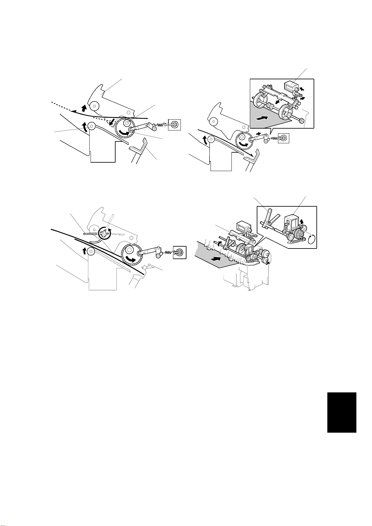
2.3 PAPER SHIFT MECHANISM
[B]
[C]
A763D569.PCX
[A]
[F]
A763D104.WMF
[G]
[A]
A763D570.PCX
In sort and stack mode, only the 1st sheet of copy paper from the 2nd set is shifted
to the front to separate each set of copies.
When the copy paper comes into the staple tray [A], the upper exit guide [B] (whi ch
contains the upper exit roller) opens. The paper switches back to the stopper [C].
Then the front guide release solenoid [D] turns on and the front guide [E] is
released, the shift motor moves jogger fence [F] to the front, and the copy paper
shifts to the front by 30 mm.
[E]
[D]
After copy paper has been shifted, the upper exit guide closes and the lower exit
roller [G] turns in the opposite direction to feed out the copy paper.
A763-10
Page 14
January 31, 2000 PAPER POSITIONING MECHANISM
2.4 PAPER POSITIONING MECHANISM
[F]
[C]
[A]
[B]
[E]
[D]
A763D105.WMF
A763D106.WMF
[G]
[H]
[G]
A763D108.WMF
A763D111.WMF
When the tr ailing edge of the 1st copy paper passes the 2nd tran sport roller [A],
the lower exit roller [B] stops and turns reverse. At the same time, the upper guide
plate motor turns on and opens the upper exit guide [C]. The copy paper is sent to
the stopper [D] by the lower exit roller and feed belt [E], and it is aligned the by
jogger motor.
The feed belt solenoid [F] turns on to move the feed belt to the stopper. This
function prevents excessive buckling of the paper between belt and stopper.
The paddles [G] send the paper to the stopper starting from the 2nd copy paper.
When the trailing edge of the 2nd copy paper passes the 2nd transport roller, the
paddle solenoid [H] turns on and the drive from the transport roller transmits to the
paddle shaft.
A763-11
Options
Page 15
STAPLER UNIT MOVEMENT MECHANISM January 31, 2000
2.5 STAPLER UNIT MOVEMENT MECHANISM
2.5.1 DRIVE
[A]
The stapler motor [A] drives the
stapler unit drive gear [B] via a timing
belt. The stapler unit guide has a rack
gear [C]. The stapler unit moves along
the rack gear via the stapler unit [D]
drive gear.
[D]
A763D107.WMF
2.5.2 MOVEMENT
[B]
[C]
Front and Rear Stapling
When the print key is pressed, the
stapler unit moves to the center. The
stapler unit moves to the front (or rear)
stapling position when the copy paper
comes into the finisher and stays until
the copy job finishes. It returns to home
position when the job is finished.
Tow-position Stapling
When the print key is pressed, the
stapler unit moves to the center. The
stapler unit moves to the rear stapling
position first and moves to the front
stapling position when stapling. Then it
goes back to the center until the copy
job finishes. It returns to home position
when the job is finished.
[A]
A763D114.WMF
A763-12
Page 16
January 31, 2000 STAPLER
2.6 STAPLER
[C]
[D]
[B]
A763D109.WMF
[D]
[A]
[A]
[E]
[G]
A763D571.PCX
[F]
A763D110.WMF
The staple hammer motor [A] drives the cam [B] via 2 gears [C, D] and the guide
roller on the staple hammer moves on the cam [D] . When the guide roller moves to
the highest position on the cam, the copy paper is stapled.
The stapler unit contains the cartridge set switch [E], staple end switch [F] and
staple position sensor [G].
The staple position sensor detects whether the staple sheet has come to the staple
unit or not.
A763-13
Options
Page 17
SHIFT TRAY MECHANISM January 31, 2000
2.7 SHIFT TRAY MECHANISM
[A]
[H]
[C]
[F]
[E]
[D]
A763D576.PCX
[B]
[G]
A763D572.PCX
The guide gear [A] on which the shift tray is mounted is driven by the lift motor [B]
via gear [C].
The finisher board detects the direction of the motor rotation and motor position
using the lift motor sensors 1 [D] and 2 [E].
The lift motor contains a thermoswitch [F]. When it detects 73.5º C, the finisher
board stops the lift motor until its temperature reaches approximately 40º C.
The shutter position switch [G] cuts the lift motor power for safety when the upper
exit guide plate opens.
The shift tray height sensor [H] detects the distance between the sensor and the
top of the copy paper on the shift tray.
A763-14
Page 18
January 31, 2000 BOOKLET UNIT GATE MECHANISM
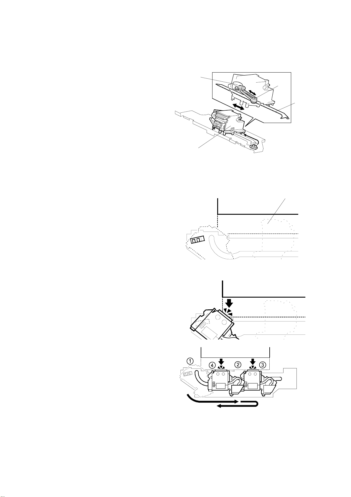
2.8 BOOKLET UNIT GATE MECHANISM
[A]
[B]
[D]
A763D550.PCX
A763D551.PCX A763D552.PCX
[C]
[A]
A763D563.PCX
There are two junction gates [A] and three paper sensors [B] at the entrance area
of the booklet unit.
Depending on paper size, the appropriate gate solenoid(s) [C] are energized to
close the gate(s) in order to transport paper to the positioning plate [D] through a
suitable paper path.
This is done for the following reasons:
• To detect the trailing ed ge of paper with the correct sensor.
• To prevent the leading edge of the next sheet from hitting the trailing edge of the
previous sheets on the positioning plate.
A763-15
Options
Page 19

BOOKLET UNIT GATE MECHANISM January 31, 2000
The following tables show the relation between paper sizes and solenoids/sensors:
A3, 11" x 17" B4, 11" x 14" A4, 8
" x 11"
1/2
1st Solenoid (Gate) OFF (Opened) ON (Closed) ON (Closed)
2nd Solenoid (Gate) OFF (Opened) OFF (Opened) ON (Closed)
A3, 11" x 17" B4, 11" x 14" A4, 8
" x 11"
1/2
Trailing Edge Sensor 1 ON ON ON
Trailing Edge Sensor 2 OFF ON ON
Trailing Edge Sensor 3 OFF OFF ON
A763-16
Page 20

January 31, 2000 RELAY ROLLER AND POSITIONING PLATE MECHANISM
2.9 RELAY ROLLER AND POSITIONING PLATE
MECHANISM
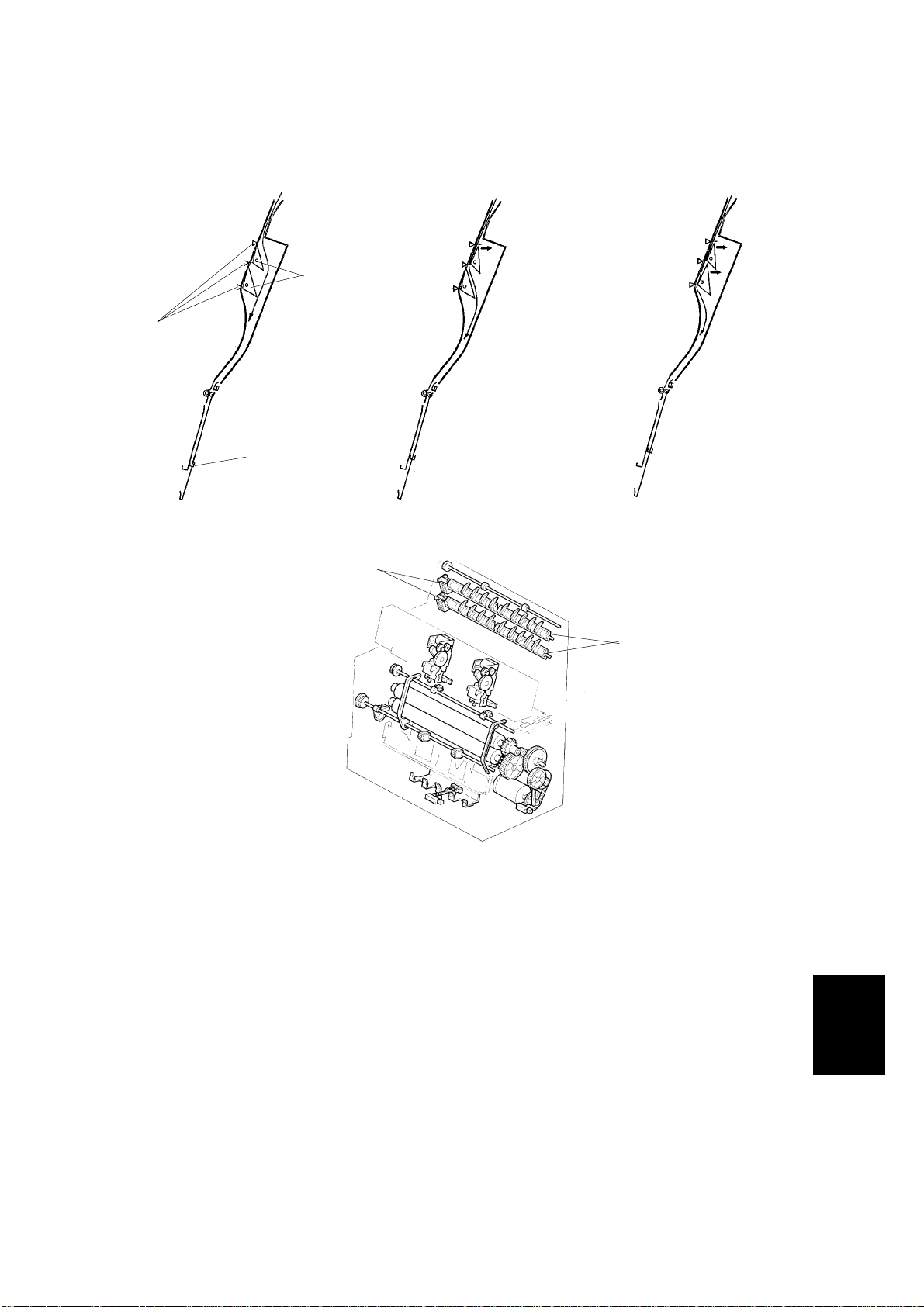
When the f irst sheet of paper comes to the booklet unit, the
booklet transport motor turns on to drive the relay roller [A].
The two relay rollers are out of contact with each other before
the paper comes. When the leading edge of the paper passes
trailing edge sensor 1, the relay roller solenoid is energized to
make the two relay rollers contact each other to transport the
paper to the positioning plate [B]. When the trailing edge of the
paper comes to the trailing ed ge sensor that the paper passes
last, the relay roller solenoid is de-energized. This solenoid
on/off cycle is done for each sheet of paper.
Before paper comes, the positioning plate moves up from the
home position to a position that is suitable for the selected
paper size in order that the middle of the paper just comes to
the stapling position.
[A]
[B]
A763D573.PCX
The positioning plate motor drives the positioning plate using
pulse counts.
Only when the first sheet of paper reaches the positioning
plate, the positioning plate sensor [C] detects the paper.
A763D574.PCX
[A]
[C]
[B]
Options
A763D563.PCX
A763-17
Page 21

POSITIONING ROLLER MECHANISM January 31, 2000
2.10 POSITIONING ROLLER MECHANISM
[C]
[E]
[D]
[A]
[E]
[B]
[D]
A763D554.PCX
[C]
[A]
A763D555.PCX
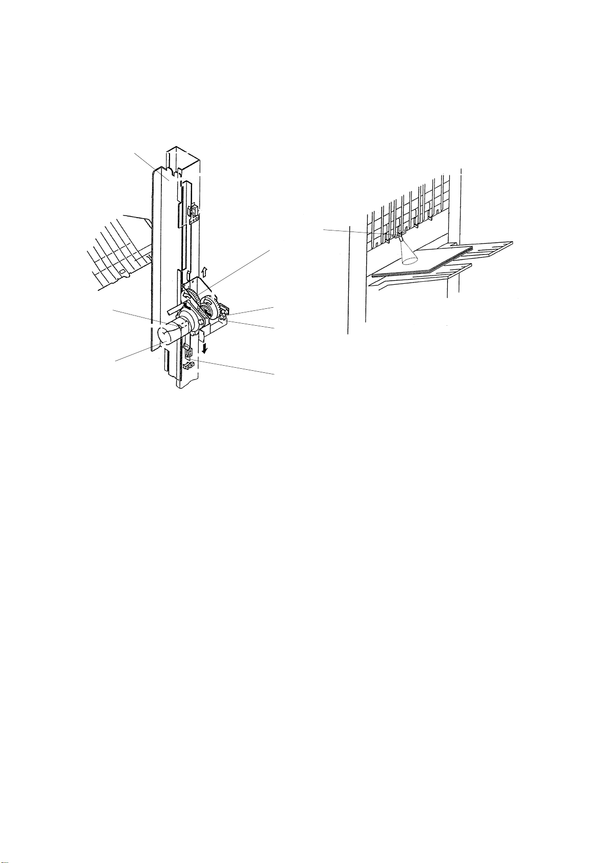
The booklet transport motor also drives the positioning roller [A] to vertically align
paper against the positioning plate [B].
The positioning roller is not round but elliptical in shape so that it moves away from
the paper while the paper is being horizontally aligned.
The positioning roller sensor [C] detects the actuator [D] on the roller shaft to
determine the rotation of the positioning roller. When the sensor is de-actuated, the
roller is away from the paper and the jogger fences [E] start moving.
A763-18
Page 22

January 31, 2000 BOOKLET UNIT JOGGER MOVEMENT MECHANISM
2.11 BOOKLET UNIT JOGGER MOVEMENT MECHANISM
[A]
[B]
A763D557.PCX
When the start key is pressed, the booklet jogger motor turns on to move the
jogger fences [A] to the waiting positions that a r e 10 mm from each of the paper
side edges .
Each time a sheet of paper reaches the positioning plate [B], the jogger fences
move toward the paper to align the paper once. The fences move back a short
distance and move forward again the paper to align for the second time. Then, the
fences go back to the waiting position.
When the la st sheet is aligned, the fences stay at the aligning positions during
stapling.
A763-19
Options
Page 23

BOOKLET STAPLER UNIT Januar y 31, 2000
2.12 BOOKLET STAPLER UNIT
A763D575.PCX
There are two staplers whose positions are fixed.
When the jogger fences finish aligning the last sheet, t he jogger fences stay at the
aligning positions and stapling starts. The two staplers do not operate at the same
time, the rear stapler operates first, then the front one. This is for the following
reasons:
• To prevent paper from becoming waved in the area between the two stapled
positions.
• To minimize necessary electric power.
The staple hammer HP switch in each stapler detects a stapling cycle and the
staple end sensor detects the presence of staples in the cartridge.
The stapler unit, including the two staplers, can be pulled out to enable staple
cartridge replacement or jam removal. The stapler unit set sensor detects when the
stapler unit is back in the right position.
A763-20
Page 24

January 31, 2000 PAPER FOLDER MECHANISM
2.13 PAPER FOLDER MECHANISM
[C]
[A]
[B]
[B]
[A]
A763D560.PCX
20 mm
A763D561.PCX
A763D559.PCX
A763D562.PCX
The positioning plate moves down from the stapling position to a position such that
the middle of the paper just comes to the folding position. It depends on the paper
size.
At the same time, the shutter guide motor moves the shutter guide, which is
covering the folder rollers to prevent paper arriving at the positioning plate from
being caught by the rollers, down to the home position.
Shortly after that, the folder plate motor and the folder roller motor start rotating.
The folder plate [A] moves to push the middle of the stapled sheets of paper
toward the folder rollers [B] until the folder plate return sensor [C] is de-actuated.
Then, the folder plate comes back to the home position.
After that, the folder rollers and booklet exit roller feed the paper to the booklet tray.
A763-21
Options
Page 25

PAPER FOLDER MECHANISM January 31, 2000
In the case of 10 sheets or more of A4 or 8
" x 11" paper, folding is done twice for
1/2
20 mm of the leading edge to fold the paper more firmly.
When the leading edge of the folded paper passes 20 mm from the folder rollers,
the folder roller motor reverses to feed the paper back 20 mm. During this action,
the folder plate stays at the return position. (Figure A763D561)
Then, the folder roller motor rotates forward again to feed the set of papers out and
the folder plate goes back to the home position. (Figure A763D562)
A763-22
Page 26

January 31, 2000 ACCESSORY CHECK
3. INSTALLATION
3.1 ACCESSORY CHECK
Check the quantity and condition of the accessories in the box against the following
list.
Description Q’ty
1. Upper Tray.......................................................................... 1
2. Shift Tray.............................................................................1
3. Tapping Screw -M4 x 6....................................................... 1
4. Rail Ass’y............................................................................ 1
5. Joint Bracket....................................................................... 1
6. Tapping Screw - M4 x 16.................................................... 2
7. Rail Bracket......................................................................... 1
8. Tapping Screw - M4 x 6...................................................... 1
9. Harness Cover.................................................................... 1
10. Sensor Feeder.................................................................. 1
7
4
9
10
5
2
1
3
6
8
A763-23
A763I101.WMF
Options
Page 27

INSTALLATION PROCEDURE January 31, 2000
3.2 INSTALLATION PROCEDURE
A763I102.WMF
A763I104.WMF
CAUTION
ø
Keep the power cord unplugged when starting the following procedure.
1. Unpack the finisher and remove the tapes and shipping retainers.
A763-24
Page 28

January 31, 2000 INSTALLATION PROCEDURE
[A]
[B]
A763I105.WMF
[E]
[D]
2. Open the front under door and pull out the staple unit [A].
3. Remove the stapler unit lock plate [B] (1 screw).
4. Push in the stapler unit and shut the front lower door.
5. Remove the right lower cover [C] (4 screws).
6. Remove the front pressure release bracket [D] (1 screw).
7. Remove the rear pressure release bracket [E] (1 screw).
[C]
A763I103.WMF
Options
A763-25
Page 29

INSTALLATION PROCEDURE January 31, 2000
[A]
[B]
[C]
A763I106.WMF
[D]
A763I107.WMF
8. Set the hooks [A] of the shift tray [B] in the notches in the shift tray bracket, and
secure the tray with two M4 x 6 screws.
9. Connect the shift tray sensor harness [C].
10. Install the harness cover [D] (2 hooks).
A763-26
Page 30

January 31, 2000 INSTALLATION PROCEDURE
[A]
[B]
A763I108.WMF
[D]
[E]
[C]
A763I110.WMF
11. Install the upper tray [A] (2 pins).
12. Attach the sensor feeler [B] (2 pins).
13. Attach the rail [C] to the rail bracket [D] as shown.
14. Install the rail bracket [E] on the left lower cover of the copier (2 screws).
A763-27
Options
Page 31

INSTALLATION PROCEDURE January 31, 2000
[A]
[C]
[D]
A763I109.WMF
[B]
A763I111.WMF
15. Install the joint bracket [A] on the left side of the copier (4 screws).
16. Secure the rail [B] to the booklet finisher with 1 M4 screw.
17. Align the finisher on the joint bracket and lock the 2 hooks [C] of the finisher on
the joint bracket.
18. Connect the finisher cable [D] to the copier.
19. Plug in the power cord and turn the main switch on, and perform stapler initial
setting as follows.
1) Enter User Program mode.
2) Press System Settings.
3) Press Basic Page 2.
4) Press Staple Initialization.
5) Press the OK key.
A763-28
Page 32

January 31, 2000 REMOVAL
4. REPLACEMENT AND ADJUSTMENT
4.1 REMOVAL
4.1.1 UPPER DOOR
[A]
A763R579.PCX
1. Open the upper door [A].
2. Remove the lower hinge [B] (1 screw).
3. Push up the upper door and remove it.
[B]
Options
A763-29
Page 33

REMOVAL January 31, 2000
4.1.2 UPPER REAR COVER
[A]
[B]
A763R580.PCX
[C]
1. Hold up the proof tray and open the top cover [A].
2. Unhook the upper rear cover [B] and remove it (3 screws).
4.1.3 LOWER REAR COVER
1. Remove the lower rear cover [C] (4 screws).
A763R104.WMF
A763-30
Page 34

January 31, 2000 REMOVAL
4.1.4 TOP COVER
[A]
[B]
[B]
[C]
A763R580.PCX
1. Hold up the upper tray [A] and open the top cover [B].
2. Push the hooks [C] of the top cover and remove it.
4.1.5 UPPER INNER COVER
A763R581.PCX
[A]
1. Open the upper door.
2. Remove the upper inner cover [A] (1 screw).
A763-31
A763R582.PCX
Options
Page 35

REMOVAL January 31, 2000
4.1.6 SHIFT TRAY UNIT
[D]
[C]
A763R106.WMF
[E]
[B]
[A]
A763R107.WMF
[F]
A763R108.WMF
1. Remove the upper and lower rear covers.
2. Disconnect the connector [A] and remove the grounding wire [B]
(1 screw).
3. Unhook the two stoppers [C] and remove them.
4. Remove the slide guide [D] by pulling it u p.
Remove the shift tray unit [E] by pulling it up.
5.
NOTE:
When reinstalling the shift tray unit, release the clutch gear [F] of the
tray lift motor by carefully inserting a screwdriver.
A763-32
Page 36

January 31, 2000 REMOVAL
4.1.7 UPPER SHIFT GUIDE
[A]
A763R112.WMF
1. Remove the slide guide and shift the shift tray unit down by releasing the clutch
gear of the tray lift motor (see Shift Tray Unit Removal).
Remove the upper
2.
shift guide [A] (6 screws (5 x M4, 1 x M3)).
4.1.8 LOWER SHIFT GUIDE
[A]
A763R109.WMF
1. Remove the shift tray unit.
2. Remove the lower shift guide [A] (2 connectors, 6 screws (3 x M4, 3 x M3)).
Options
A763-33
Page 37

REMOVAL January 31, 2000
4.1.9 EXIT UNIT
[B]
[C]
[A]
A763R113.WMF
[G]
[D]
[E]
A763R114.WMF
1. Remove the shift tray unit, and the upper and lower shift guides.
2. Disconnect the connector [A] and remove the screw [B] that secures the
transport belt unit [C].
3. Disconnect the 4 connectors [D].
4. Hold up the exit unit [E] and remove it with the transport belt unit
(3 screws, 1 clamp).
NOTE:
When installing the exit unit, make su re to position the exit uni t guide
plate (black) [F] over the transport guide plate [G].
[F]
A763-34
Page 38

January 31, 2000 REMOVAL
4.1.10 BUFFER ROLLER UNIT
A763R583.PCX
[D]
[A]
[B]
[C]
A763R112.WMF
[D]
[E]
A763R584.PCX
A763R585.PCX
1. Remove the upper rear cover and the top cover.
2. Disconnect the connector [A].
3. Remove the upper shift guide [B] (6 screws) and the guide holder [C] (2
screws).
4. Unhook the shafts [D], and remove the buffer roller unit [E] (2 clamps).
Options
A763-35
Page 39

REMOVAL January 31, 2000
4.1.11 STAPLER
[A]
[B]
A763R586.PCX
[C]
A763R588.PCX
1. Open the upper front door.
2. Slide the stapler [A] towards the front.
3. Remove the stapler (1 screw, 1 connector [B]).
4. Remove the cover [C] from the stapler (2 screws).
A763R587.PCX
A763-36
Page 40

January 31, 2000 REMOVAL
4.1.12 FINISHER BOARD
[A]
A763R589.PCX
1. Remove the upper rear cover.
2. Remove the finisher board [A] (4 screws, 19 connectors).
NOTE:
Do the following adjustments after replacing the board:
• Shift tray height
• Jogger fence position
• Stapling position
A763-37
Options
Page 41

REMOVAL January 31, 2000
4.1.13 BOOKLET UNIT
[D]
[A]
[B]
[C]
A763R561.WMF
1. Remove the following items.
• Upper and lower rear covers.
• Shift tray unit.
• Lower shift guide.
2. Remove the lower right cover [A] (4 screws).
3. Remove the folder roller knob [B] (1 stepped screw).
4. Remove the lower inner cover [C] and lower door [D] (5 screws).
A763-38
Page 42

January 31, 2000 REMOVAL
[A]
[B]
[C]
[D]
[G]
A763R110.WMF
[E]
A763R101.WMF
A763R111.WMF
[F]
[H]
[I]
[I]
[J]
5. Remove the grounding wire [A] (1 screw) and upper booklet exit guide [B]
(2 screws).
6. Open the lower booklet exit guide [C] and remove it
(1 L-pin [D], 2 connectors [E]).
7. Remove the right front and right rear covers [F , G] (2 screws each).
8. Disconnect the two connectors [H].
9. Remove the two joints [I] and then pull out the booklet unit [J] from the right
side (3 screws).
A763-39
Options
Page 43

REMOVAL January 31, 2000
4.1.14 FOLDER ROLLERS
[A]
A763R590.PCX
[B]
A763R591.PCX
[C]
[D]
A763R592.PCX
1. Remove the booklet unit
2. Remove the drive unit [A] (4 connectors [B], 3 screws [C]).
3. Remove the front and rear tension springs [D].
[D]
A763R593.PCX
A763-40
Page 44

January 31, 2000 REMOVAL
[A]
4-105B.PCX
A763R595.PCX
A763R596.PCX
[B]
[B]
[C]
A763R597.PCX
A763R598.PCX
[C]
Remove
4.
the gears [A] and ball bearings [B] (4 C-rings).
5. Remove the front and rear tighteners [C] (1 stepped screw each).
A763-41
Options
Page 45

REMOVAL January 31, 2000
A763R599.PCX
[A]
6. Remove the jogger plates [A] (1 screw each).
7. Slide the folder rollers [B] to the front and remove them.
[B]
A763R549.PCX
A763-42
Page 46

January 31, 2000 REMOVAL
4.1.15 FOLDER PLATE
[D]
A763R117.WMF
[C]
[B]
[D]
[E]
A763R116.WMF
Removal
1. Remove the following items
• Lower right cover (see “Booklet Unit Removal”)
• Folder rolle r knob (see “Booklet Unit Removal”)
• Lower door and lower inner cover (see “Booklet Unit Removal”)
• Booklet board
2. Release the harness [A] from the clamps.
3. Insert two positioning screws [B] in the holes provided in the folder table [C].
4. Tighten the screws until the ends touch the securing plate [D] for the folder
plate.
5. Remove the folder plate [E] and the securing plate (3 screws).
[A]
A763-43
Options
Page 47

REMOVAL January 31, 2000
Reinstalling
[B]
[C]
[B]
[A]
[A]
A763R575.PCX
A763R578.PCX
[A, B]
[D]
A763R577.PCX
A763R576.PCX
1. Line up the two small holes [A] in the folder plate with the two small protrusions
on the bottom of the securing plate [B]. Then, push the two protrusions through
the holes.
Note: Be sure that the three screw holes are also lined up.
[E]
2. Temporarily fix the two plates together by attaching two strips of electrical tape
[C] along the line where they meet (see the illustration).
NOTE:
1) Be sure to fold the two strips back toward you so that they can
easily be removed.
2) Be careful not to attach the tape too close to the three screw holes.
3. Reattach the two plates [A, B] to the folder table [D] (3 screws).
NOTE:
Tighten these three screws while holding the securing plate against
the two positioning screws [E] that were installed in step 3 of the
"Removal" procedure.
4. Remove the two strips of tape.
A763-44
Page 48

January 31, 2000 REMOVAL
4.1.16 BOOKLET STAPLER UNIT
Removal
[A]
[B]
A763D562.PCX
[C]
A763R563.PCX
1. Remove the lower door and inner cover (see “Booklet Unit Removal”).
2. Remove the guide roller [A] and shaft [B] (1 E-ring).
3. Pull out the booklet stapler unit [C].
Options
A763-45
Page 49

REMOVAL January 31, 2000
[A]
A763R564.PCX
[C]
A763R567.PCX
Adjustment
1. Remove the booklet stapler cover [A] (3 screws).
2. Remove the three paper guides [B] (1 screw each).
3. Loosen the two screws on each of the anvils [C].
[B]
A763R565.PCX
A763-46
Page 50

January 31, 2000 REMOVAL
[A]
[B]
A763R568.PCX
[A]
A763R569.PCX
[C]
[A]
[D]
A763R570.PCX
4. Insert the anvil positioning plate [A] into the staple slot of the stapler [B].
NOTE:
The anvil positioning plate is stored in the booklet stapler cover [C].
5. Rotate the gear to move down the stapler. Then align the anvil positioning plate
and the anvil [D]. Then secure the anvils (2 screws each).
A763-47
Options
Page 51

REMOVAL January 31, 2000
4.1.17 BOOKLET BOARD
[B]
[A]
A763R115.WMF
1. Remove the lower right cover [A] (4 screws).
2. Remove the booklet board [B] (4 screws, 14 connectors).
NOTE:
After replacing the board, adjust the booklet stapling position.
4.1.18 POSITIONING PLATE UNIT
[C]
A763R571.PCX
1. Remove the booklet board (4 screws, 14 connectors).
[D]
2. Slide the paper positioning unit [C] to the right and remove it (2 screws, 2
connectors [D]).
A763-48
Page 52

January 31, 2000 REMOVAL
4.1.19 1ST AND 2ND BOOKLET UNIT GATES
[E]
[A]
[A]
[B]
A763R572.PCX
[D]
[C]
A763R573.PCX
A763R574.PCX
1. Remove the upper and lower rear covers.
2. Release the two tension springs [A] of the booklet entrance guide [B].
3. Remove the booklet unit gate solenoids [C] (1 screw and 1 spring each).
4. Pull out the link of the solenoid [D].
5. Remove the booklet unit gates [E].
A763-49
Options
Page 53

ADJUSTMENT January 31, 2000
4.2 ADJUSTMENT
4.2.1 SHIFT TRAY HEIGHT
SW1
LED 1
SW2
Dip Switch 3
Dip Switch 3
ON
1
LED 2
A763R550.WMF
23 56784
A763R551.WMF
After replacing the finisher board or shift tray height sensor, always do this
adjustment.
1. Remove the upper rear cover.
2. Turn on dip switches 3 -1 and -4 on the finisher board.
3. Put blank paper (A4/8
11") on the shift tray.
1/2" x
4. Press switch 1 (SW1) on the finisher board.
The finisher automatically adjusts the shift tray height when switch 1 is pressed.
• After performing the adjustment, the shift tray will return to home position.
• During the adjustment, LED 1 flashes. After performing the adjustment, LED
1 turns on and remains on.
• If the automatic adjustment fails, the finisher stops and LED 1 turns off.
5. Turn off dip switches 3 -1 and -4, then turn off the copier main switch.
A763-50
Page 54

January 31, 2000 ADJUSTMENT
4.2.2 JOGGER FENCE POSITION
Dip Switch 3
ON
1
23 56784
SW1
SW2
A763R552.WMF
Dip Switch 3
LED 1
LED 2
A763R550.WMF
Jogger Fence
Jogger Fence
Rear
Front
Shutter
A763R553.WMF
After replacing the finisher board or if a paper alignment fault occurs, do this
adjustment.
SW2
SW1
Doing this adjustment once will affect all paper sizes.
1. Remove the upper rear cover.
2. Turn on dip switch 3-1 on the finisher board.
3. Press the following switch on the finisher board.
Using A4: Switch 1 (SW1)
Using 8
" x 11": Switch 2 (SW2)
1/2
• After pressing the switch, the upper exit unit will open and the jogger fences
will move to the A4 or 8
4. Place 10 sheets of A4/8
" x 11" position.
1/2
" x 11" paper between the jogger fences and push
1/2
them until they touch the shutters.
5. Adjust the jogger fence position by pressing switch 1 or 2.
• Switch 1: Move to the front (0.35 mm/press)
• Switch 2: Move to the rear (0.35 mm/press)
6. Press switches 1 and 2 simultaneously to store the adjustment data.
• After pressing the switches, the upper exit unit will close.
7. Turn off dip switch 3-1, then turn off the copier main switch.
Options
A763-51
Page 55

ADJUSTMENT January 31, 2000
4.2.3 STAPLING POSITOIN
290 ± 2 mm (A4Y), 273 ± 2 mm (LTR)
Dip Switch 3
Staple
Rear Front
SW2
SW1
A763R555.WMF
ON
1
23 56784
A763R554.WMF
After replacing the finisher board, do this adjustment. Doing this adjustment once
will affect all paper sizes and all stapling positions.
1. Remove the upper rear cover.
2. Turn on dip switches 3 -1 and -2 on the finisher board.
3. Press the following switch on the finisher board.
Using A4: Switch 1 (SW1)
Using 8
" x 11": Switch 2 (SW2)
1/2
• After pressing the switch, the upper exit unit will open and the transport belt
will rotate.
4. Within five seconds after pressing the switch, place one sheet of A4/8
1/2
paper between the jogger fences and push it until it touches the shutter.
When the staple tray paper senso r detects the paper, the stapler will staple
(rear, 1 point).
5. Take out the stapled paper manually and check the staple position.
Staple position: Good → Tur n o ff dip swi tches 3 -1 and -2 to end the
procedure.
Staple position: No good → Change the staple position by doing the
following steps.
6. Adjust the staple position by pressing switch 1 or 2.
Switch 1: Move the front (0.3 mm/press)
Switch 2: Move to the rear (0.3 mm/press)
7. Press switches 1 and 2 simultaneously to store the adjustment data. After
pressing the switches, check the staple position again.
8. Turn off dip switches 3 -1 and -2, then turn off the copier main switch.
A763-52
" x 11"
Page 56

January 31, 2000 ADJUSTMENT
4.2.4 BOOKLET STAPLING POSITION
Dip Switch 1
LED 1
SW2
A763R557.WMF
Mark
(Trailing edge)
Dip Switch 1
ON
1
23 56784
A763R556.WMF
Slot in direction
(reading edge)
A763R558.WMF
After replacing the booklet board, dip switches 1 -6, -7, -8 on the new board must
be set up the same way as on the old board.
1. Remove the lower right cover (see “Booklet Unit Removal”) and lower rear
cover.
2. Turn on dip switches 1 -1 and -2 on the booklet board.
3. Tape the actuators of the booklet entrance guide sensor (S42) and the booklet
entrance guide safety switch (SW11), so that S42 and SW11 remain actuated.
4. Press switch 2 (SW2) on the booklet board.
• After pressing the switch, the booklet transport motor (M10) will start to
rotate.
5. Put a mark on the trailing edge of some A3/11" x 17" paper (two sheets).
Options
A763-53
Page 57

ADJUSTMENT January 31, 2000
[B]
[A]
A763R548.PCX
6. Open the booklet entrance guide [A], then slide in the two sheets of paper [B]
until their leading edges touch the positioning plate.
7. Press switch 2 on the booklet board.
• The booklet finisher makes a booklet automatically.
A763-54
Page 58

January 31, 2000 ADJUSTMENT
Adjust towards the leading edge
Mark
Folding Position
L
Stapling Position
Example 1: L= 1 mm
Dip switch 1 -6, -7, -8 setting
-6 -7 -8
Adjust away from the leading edge
Stapling Position
L
Folding Position
Example 2: L= 0.75 mm
Adjustment
(0.25 mm/ step)
OFF ON ON +3
OFF ON OFF +2
OFF OFF ON +1
OFF OFF OFF 0
ON OFF ON -1
ON ON OFF -2
ON ON ON -3
ON OFF OFF Do not use
Mark
A763R559.WMF
8. Measure the distance (L) between the stapling position and the folder position.
9. Adjust the stapling position with dip switches 1 -6, -7, -8.
Inputting a lower value than the current setting moves the stapling position
towards the leading edge. Adjusting by 1 step moves the stapling position 0.25
mm.
Example 1:
To move the stapling position 1 mm towards the leading edge.
If dip switch 1 is currently set to +2, set the dip switch to reflect -2 (this moves
the stapling position 4 steps towards the leading edge).
Example 2:
To move the stapling position 0.75 mm away from the leading edge.
If dip switch 1 is currently set to -1, set the dip switch to reflect +2 (this move,s
the stapling position 3 steps away from the leading edge).
10. Turn off dip switched 1-1 and -2, then turn off the copier main switch.
A763-55
Options
Page 59

ELECTRICAL COMPONENT LAYOUT (A763) (1/2)
20
19
18
17
16
21
50
46
47
60
48
49
53
54
55
56
66
67
68
69
70
71
72
73
74
75
44
1
2 3
4
52
5
6
7
8
9
10
11
12
51
45
22
43
42
41
40
39
23
24
25
131415
59
61
26
62
63
27
28
29
30
58
57
64
77
76
78
79
80
81
82
84
38
37
31
32
343536
33
65
83
85
86
8788
Page 60

ELECTRICAL COMPONENT LAYOUT (A763) (2/2)
Symbol Name
Motors
M1 Entrance 49 E3
M2 Transport Roller 47 E2
M3 Buffer Roller 48 E3
M4 Jogger 44 E2
M5 Stapler 52 A6
M6 Staple Hammer 51 A7
M7 Guide Plate 46 E4
M8 Exit Motor 45 E3
M9 Tray Lift 50 E2
M10 Booklet Transport 56 I1
M11 Positioning Plate 54 I2
M12 Shutter Guide 55 I2
M13 Booklet Jogger 57 I2
M14 Front Stapler 60 I4
M15 Rear Stapler 53 I5
M16 Folder Roller 59 I1
M17 Folder Plate 58 I1
Symbol Name
Switches
SW1
SW2 Shift Tray Safety 82 E6
SW3 Shutter Position 76 E7
SW4
SW5
SW6
SW7 Cartridge Set 83 A7
SW8 Staple End 83 A7
SW9 Thermo 78 E2
SW10
SW11
SW12
SW13
SW14
Upper Cover
Safety
Upper Exit Guide
1
Upper Exit Guide
2
Shift Tray Upper
Limit
Lower Door
Safety
Booklet Entrance
Guide Safety
Booklet Exit
Safety
Front Staple
Hammer HP
Rear Staple
Hammer HP
Index
No.
Index
No.
77 E6
80 E6
79 E7
81 E6
87 I5
84 I5
88 I6
86 I4
85 I5
P to P
P to P
Symbol Name
Sensors
S1 Entrance 3 A2
S2
S3 Straight Path 21 A5
S4 Staple Tray Paper 8 A2
S5 Jogger HP 19 A3
S6 Stapler Unit HP 16 A4
S7
S8 Staple Position 14 A7
S9 Upper Exit Guide 4 A2
S10 Exit Guide Motor 7 A6
S11 Exit 18 A3
S12 Exit Motor 13 A3
S13 Shift Tray Paper 20 A5
S14 Shift Tray height 1 A2
S15 Shift Tray HP 12 A4
S16 Lift Motor 1 11 A4
S17 Lift Motor 2 10 A4
S18 Proof Tray Exit 5 A6
S19 Proof Tray Limit 6 A6
S20 Finisher Set 20 A6
S21 Shutter 15 A3
S22 Trailing Edge 1 24 F3
S23 Trailing Edge 2 23 F3
S24 Trailing Edge 3 22 F4
S25 Booklet Entrance 32 F5
S26
S27
S28 Positioning Roller 31 F3
S29
S30 Front Staple End 43 I3
S31 Rear Staple End 25 I4
S32 Stapler Unit Set 26 F5
S33 Shutter Guide HP 33 F3
S34 Folder Plate HP 29 F3
S35
S36
S37
Buffer Roller
Entrance
Staple Hammer
HP
Positioning Plate
Paper
Positioning Plate
HP
Booklet Jogger
HP
Folder Plate
Return
Folder Plate
Motor
Folder Roller
Position
Index
No.
2 A5
14 A7
34 F2
35 F2
39 F4
30 F6
36 F5
28 F6
P to P
Symbol Name
Sensors
S39
S40 Booklet Exit 41 F2
S41
S42
S43 Lower Door 42 F5
S44
S45 Upper Door 16 F6
Symbol Name
Solenoids
SOL1 Booklet Gate 72 E4
SOL2
SOL3 Proof Tray Gate 70 E5
SOL4
SOL5 Transport Belt 69 E5
SOL6 Paddle 67 E5
SOL7
SOL8
SOL3
SOL4 Relay Roller 75 I3
PCBs
PCB1 Finisher 61 C7
PCB2 Lift Motor Sensor 63 A4
PCB3 Booklet Unit 65 G6
PCB4
Others
HR1 Stapler Interface 62 -
Folder Roller
Motor
Booklet Tray
Paper
Booklet Entrance
Guide
Booklet Exit
Cover
Buffer Roller
Entrance Gate
Buffer Roller Exit
Gate
Front Guide
Release
1st Booklet Unit
Gate
2nd Booklet Unit
Gate
Trailing Edge
Sensor
Index
No.
37 F4
40 F2
27 F4
38 F5
Index
No.
71 E4
68 E4
66 E5
73 I3
74 I3
64 F3
P to P
P to P
Page 61

1
Shift Tray
Height Sensor
2
3
4
5
6
7
Upper Exit
Guide Sensor
Staple Tray
Paper Sensor
Jogger HP
Shutter Sensor
Exit Sensor
Exit Motor
Finisher Set
Shift Tray HP
Stapler HP
Lift Motor Sensor Board
Lift Motor 1
Lift Motor 2
Shift Tray
Paper Sensor
Upper Door
Buffer Roller
Straight Path
Sensor
Exit Guide
Motor Sensor
Proof Tray Exit
Proof Tray Limit
Staple Motor
Staple Position
Sensor
Staple Hammer HP
Sensor
Cartridge Set Switch
Staple End Switch
Staple Hammer
A B C D E F G H I
CN1-1
Copier
Entrance
Sensor
Sensor
Sensor
Sensor
Sensor
Sensor
Sensor
Sensor
Sensor
Entrance
Sensor
Sensor
Sensor
Motor
S14
S1
S9
S4
S5
S21
S11
S12
S20
S15
S6
S16
PCB2
S17
S13
S22
S2
S3
S10
S18
S19
M5
S8
S7
M6
SW7
SW8
CN114-1
CN106-3
CN127-3
CN122-1
CN121-1
CN118-1
CN134-3
CN112-3
CN117-1
CN130-3
CN129-3
CN400-3
CN400-6
CN101-3
CN113-1
CN105-3
CN110-3
CN501-1
CN502-1
CN503-1
CN306-1
CN207-1
CN212-4
-2
-3
CN202-6
-2
-1
CN204-1
-2
-1
CN207-1
-2
-3
CN207-4
-2
-3
CN205-1
-2
-3
CN207-7
-2
-1
CN207-10
-2
-1
-2
-3
-2
-1
CN210-1
-2
-1
-2
-1
-5
-4
CN1010
-1 -1
-2
-2
-1
-3
-2
-3
CN202-4
-2
-1
CN203-1
-2
-1
-2
-3
-2
-1
-2
-1
CN304-5
-3
-2
-1
-5
-4
-2
-3
-2
-3
-5
-6
-2
-3
-8
-9
-13
-12
-2
-3
CN201
-2
-3
-5
-6
-2
-3
CN18-1
CN17-7
CN20-4
CN20-1
CN9-7
CN9-13
CN12-1
CN12-4
CN12-7
CN12-10
CN12-13
CN14-1
CN12-16
CN24-1
CN15-7
CN11-5
CN26-4
CN26-1
CN8-1
CN6-1
CN9-1
CN9-4
-11
-12
-17
-18
-10
-11
-12
-13CN307-7 CN305-1
-14-2 -2
-15-3 -3
-14
-15
-14
-15
-2-2
-2
-3
-4
-2
-3
-4-4
-8
-9
-5
-6
-2
-3
-5
-6
-2
-3
-8
-9
-2
-3
-5
-6
-8
-9
-2
-3
-2
-3
-8
-9
-6
-7
-5
-6
-2
-3
-2-2 -4
-3-3 -3
-4-4 -2
-5-5 -1
-6
-7
-8
-9
[24]
[0]
TXD
[0]
RXD
[0]
Not used
[0 to 5]
[0]
[5]
[5]
[0]
[s5]
[5]
[0]
[s5]
[5]
[0]
[s5]
[5]
[0]
[s5]
[0]
[s5]
[5]
[0]
[t5]
[5]
[0]
[0 or 5 Þ 0/5]
[5]
[5]
[0]
[s5]
[5]
[0]
[s5]
[5]
[0]
[s5]
[5]
[0]
[0 or 5 Þ 0/5]
[5]
[0]
[0 or 5 Þ 0/5]
[5]
[0]
[t5]
[5]
[0]
[s5]
[5]
[0]
[s5]
[5]
[0]
[s5]
[0]
[0 or 5 Þ 0/5]
[5]
[5]
[0]
[s5]
[5]
[0]
[s5]
[24 Þ 0/24] A
[24 Þ 0/24] B
[24 Þ 0/24] /A
[24 Þ 0/24] /B
[24]
[t5]
[t5] Set
[t5]
[t5]
[t5]
[5]
[0]
[t24] CW
[t24] CCW
[t24] CCW
A
Finisher Board
A
A
(PCB1)
[24]
[24]
RXD
TXD
[s24]
[s24]
[0 to 5]
[24]
[24]
/B [24 Þ 0/24]
/A [24 Þ 0/24]
B [24 Þ 0/24]
A [24 Þ 0/24]
[24]
/B [24 Þ 0/24]
/A [24 Þ 0/24]
B [24 Þ 0/24]
A [24 Þ 0/24]
[s24]
[s24]
[24]
[24]
/B [24 Þ 0/24]
/A [24 Þ 0/24]
B [24 Þ 0/24]
A [24 Þ 0/24]
[24]
[24]
/B [24 Þ 0/24]
/A [24 Þ 0/24]
B [24 Þ 0/24]
A [24 Þ 0/24]
[s24]
[s24]
[24]
[t24]
[24]
[t24]
[24]
[t24]
[24]
[t24]
[24]
[t24]
[24]
[t24]
[24]
[t24]
[24]
[s24]
[s24]
[t24]
[t24]
[s24]
[s24]
CN500-1CN19-1
CN3-1
CN7-4
CN15-1
CN10-1
CN11-10
-11
-12
-13
-14
CN11-1
CN17 -1
CN16 -1
CN11 -8
CN4-1
CN4-5
CN4-7
CN26-7
CN11-3
-14
CN4-3
CN5-1
CN5-4
CN5-7
CN5-9
-10
CN5-11
-12
CN7-1
-2
-2
-3
-4
-5
-6
-5
-2
-2
-3
-4
-5
-6
CN208-1
CN208-6
-2 -7
-2
-3
-4
-5
-6
-2
-3
-4
-5
-6
-9
-2
-6
CN203-4
-8
CN900-1
-8
CN208-8
-4
CN208-10
CN208-11
-4
-3
-5
-6
-8
-2
-3
CN115-2
CN124-5
-2
-3
-4
-5
CN107-2
CN108-2
CN109-2
-5
CN104-3
-2
CN128-2
-9
CN112-1
CN131-1
CN132-1
CN209-2
CN209-3
CN206-3
CN135-1
-3
-1
-1
CN123-3CN9-13
CN504-2
CN504-1
M9
SW9
M2
M4
M8
M1
M3
M7
SOL
SOL
SOL
SOL
SOL
SOL
SOL
SW1
SW2
SW6
SW4
SW5
SW3
1
2
4
3
6
7
5
Tray Lift Motor
Thermo Switch
Transport
Roller Motor
Jogger Motor
Exit Motor
Entrance Motor
Buffer Roller
Motor
Guide Plate
Motor
Booklet Gate
Solenoid
Buffer Roller
Entrance Gate
Solenoid
Buffer Roller
Exit Gate
Solenoid
Proof Tray Gate
Solenoid
Paddle
Solenoid
Front Guide
Release
Solenoid
Transport Belt
Solenoid
Upper Cover
Safety Switch
Shift Tray
Safety Switch
Shift Tray
Upper Limit
Switch
Upper Exit
Guide 1 Switch
Upper Exit
Guide 2 Switch
Shutter Position
Switch
-1
-2
-4
-3
-2
-1
-5
-6
-2
-1
-2
-
-2
-2
-3
-2
-1
-4
-2
-1
[0]
[0]
[0]
[0]
[0]
CN206-6
-2
-5
-4
-3
-2
-1
Positioning
Plate Paper
Sensor
Positioning
Plate HP
Sensor
Booklet Tray
Paper Sensor
Booklet Exit
Sensor
Positioning
Roller Sensor
Shutter Guide
HP Sensor
Folder Plate HP
Sensor
S26
S27
S41
S40
S28
S33
S34
Trailing Edge Sensor Board
Trailing Edge 1
Sensor
Trailing Edge 2
Sensor
Trailing Edge 3
Sensor
Booklet
Entrance Guide
Sensor
Booklet Jogger
HP Sensor
Folder Roller
Motor Sensor
Booklet Exit
Cover Sensor
Lower Door
Sensor
Folder Plate
Motor Sensor
Stapler Unit Set
Sensor
Booklet
Entrance
Sensor
Folder Plate
Return Sensor
Folder Roller
Position
PCB4
S22
S23
S24
S42
S29
S39
S44
S43
S36
S32
S25
S35
S37
CN105-3
CN106-3
CN100-3
CN325-3
CN126-3
CN127-3
CN128-3
CN123-5
CN124-3
CN101-3
CN102-2
CN103-3
CN104-3
CN107-2
CN131-3
CN132-3
CN129-3
CN501-3
CN301-1
-2
-1
CN302-1
-2
-1
CN402
-2
-1
CN425
-2
-1
-2
-1
-2
-1
-2
-1
CN210-1
-4
-3
-2 -4
-2
-1
-2
-1
-3
-1
CN303-3
-1
-2
-2
-1
-3
-1
-2
-1
CN308-1
-2
-1
-2
-1
-2
-1
-3
-2
-1
-3
-2
-1
-2
-3
-2
-3
CN302
-4
-5
-6
CN225
-2
-3
-4
-2
-3
-5-1
-1
-2
-2
-3
CN1-1
CN2-6
CN6-1
CN6-4
CN6-7
CN9-1
CN9-4
CN9-7
CN9-10
-11
-12
CN10-1
CN10-6
CN11-1
CN11-4
CN11-7
CN11-10
-11
-12
CN11-13
-14
-15
CN13-1
CN13-4
CN13-13
-14
-15
CN18-1
-2
-3
-5
-6
-8
-9
-2
-3
-5
-6
-8
-9
-7
-8
-2
-3
-5
-6
-8
-9
-2
-3
-5
-6
-2
-3
-2
-5
-4
-3
-2
-1
-2
-3
-4
-5
[24]
[0]
[0]
[24]
[0]
TXD
[0]
RXD
[5]
[0]
[s5]
[5]
[0]
[s5]
[5]
[0]
[s5]
[5]
[0]
[s5]
[5]
[0]
[s5]
[5]
[0]
[s5]
[5]
[0]
[s5]
[5]
[s5]
[s5]
[s5]
[0]
[5]
[0]
[s5]
[5]
[0]
[s5]
[0]
[0 or 5 Þ 0/5]
[5]
[5]
[0]
[s5]
[5]
[0]
[s5]
[0]
[0 or 5 Þ 0/5]
[5]
[5]
[0]
[s5]
[5]
[0]
[s5]
[5]
[0]
[s5]
Booklet Unit
[s5]
[5]
Board (PCB3)
[0]
B
B
B
[▲24]
[▲24]
[▲24]
[▲24]
[0 Þ 24/0]
[0 Þ 24/0]
[0 Þ 24/0]
[0 Þ 24/0]
[24]
/B [24 Þ 0/24]
/A [24 Þ 0/24]
A [24 Þ 0/24]
B [24 Þ 0/24]
[24]
/B [24 Þ 0/24]
/A [24 Þ 0/24]
A [24 Þ 0/24]
B [24 Þ 0/24]
[24]
/B [24 Þ 0/24]
/A [24 Þ 0/24]
A [24 Þ 0/24]
B [24 Þ 0/24]
[24]
[t24]
[24]
[t24]
[24]
[t24]
[t5]
[s5]
[0 Þ 24/0]
[0 Þ 24/0]
[0 Þ 24/0]
[0 Þ 24/0]
[t5]
[s5]
[0 Þ 24/0]
[0 Þ 24/0]
[0 Þ 24/0]
[0 Þ 24/0]
[s24]
[s24]
[s24]
B
[0]
[0]
[24]
CN4-7
-8
CN4-9
-10
CN5-1
-2
-3
-4
CN7-1
-2
-3
-4
-5
CN7-6
-7
-8
-9
-10
CN12-1
-2
-3
-4
-5
CN15-1
-2
CN15-3
-4
CN15-5
-6
CN8-1
-2
-4
-5
-6
-7
CN8-8-9CN306-7
-11
-12
-13
-14
CN4-1
-2
-3
-4
-5
-6
CN305-7
CN113-2
CN108-1
CN124-4
CN113-5
CN114-5
CN119-5
CN118-2
CN117-2
CN116-2
CN315-3
-6
-5
-4
-3
-2-4-6
-1
CN316-3
-6
-5
-4
-3
-2-4-6
-1
CN205-1
[ ]
-1
-2
-3
-2
-1
-4
-3
-2
-1
-4
-3
-2
-1
-1
-1
-1
16
17
10
-4
-3
-2
13
-1
11
12
SOL
SOL
SOL
10
Front Stapler Unit
S30
-2
-1-3
SW13
-5
M
14
-7
Rear Stapler Unit
S31
-2
-1-10
SW14
-5
-7
M
15
SW11
SW10
SW12
-2
Symbol Table
DC Line
Pulse Signal
Signal Direction
Active High
s
Active Low
t
Voltage
M
M
M
M
M
M
8
9
Folder Roller
Folder Plate
Transport Motor
Booklet Jogger
Positioning
Plate Motor
Shutter Guide
1st Booklet Unit
Gate Solenoid
2nd Booklet
Unit Gate
Relay Roller
Front Staple
End Sensor
Front Staple
Hammer HP
Front Stapler
Rear Staple
End Sensor
Rear Staple
Hammer HP
Rear Stapler
Entrance Gate
Safety Switch
Lower Door
Safety Switch
Booklet Exit
Safety Switch
BOOKLET FINISHER (A763) POINT TO POINT DIAGRAM
Motor
Motor
Booklet
Motor
Motor
Solenoid
Solenoid
Sensor
Motor
Sensor
Motor
Booklet
1
2
3
4
5
6
7
A B C D E F G H I
 Loading...