

Page 1

3,000-SHEET FINISHER
(Machine Code: A697)
Page 2
June 30, 1998 SPECIFICATIONS
1. OVERALL MACHINE INFORMATION
1.1 SPECIFICATIONS
The punch unit is an option for this machine.
Paper Size: No punch mode
Shift Tray: A3 to B5/DLT to LT
(B6 lengthwise in no shift mode and no
staple mode)
Upper Tray: A3 to A6 lengthwise/DLT to HLT
Punch mode
2 holes: A3 to A5/DLT to LT
3 holes: A3, B4, A4 sideways, B5 sideways
DLT, LT sideways
Paper Weight: No punch mode
No staple mode: 52 g/m2 ~ 157 g/m2, 14 ~ 42 lb
Staple mode: 64 g/m2 ~ 80 g/m2, 17 ~ 21 lb
Punch mode
2 holes: 52 g/m2 ~ 128 g/m2, 14 ~ 34 lb
3 holes: 52 g/m2 ~ 105 g/m2, 14 ~ 28 lb
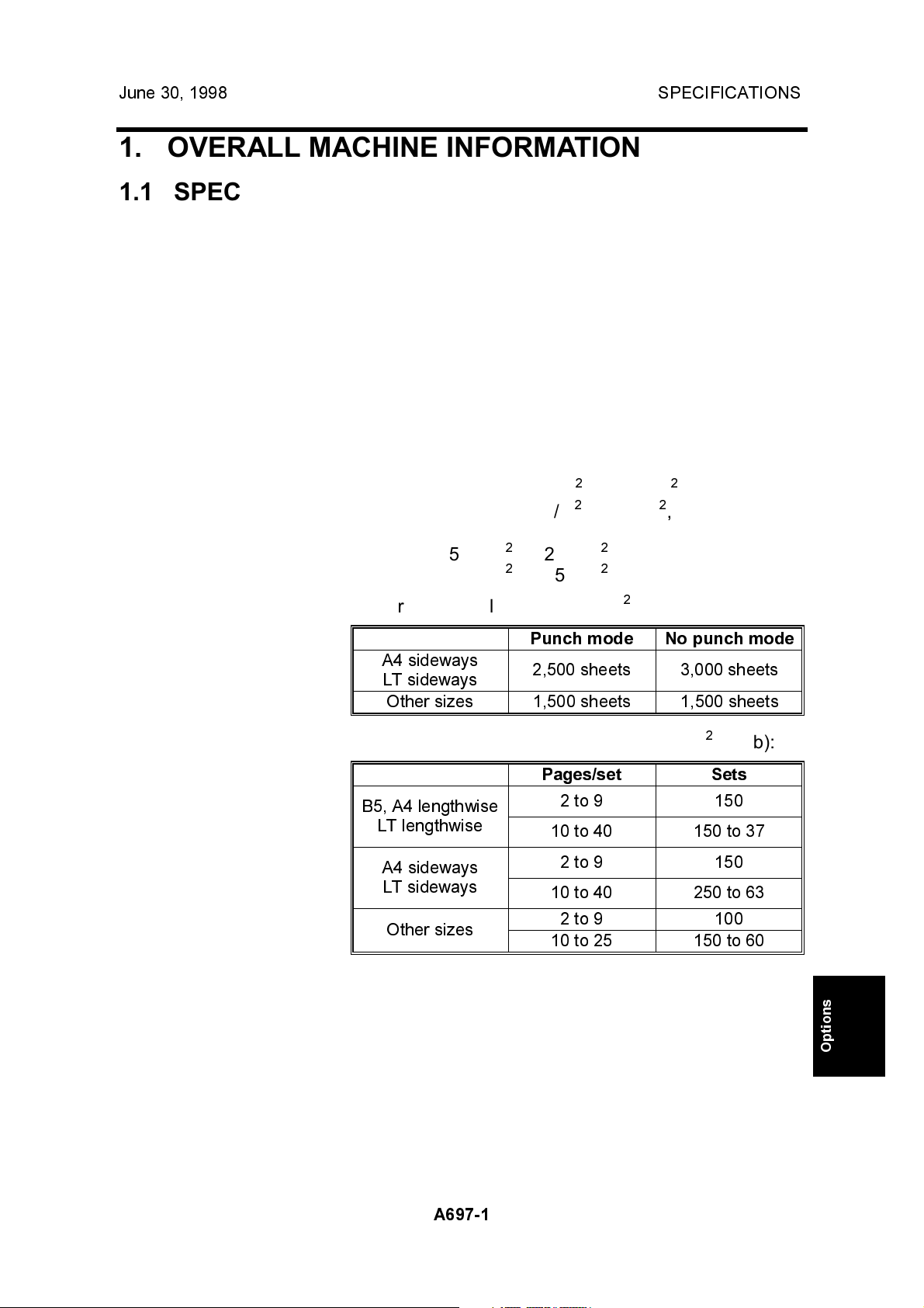
Paper Capacity: Shift tray/no staple mode (80 g/m2, 20 lb):
Punch mode No punch mode
A4 sideways
LT sideways
Other sizes 1,500 sheets 1,500 sheets
2,500 sheets 3,000 sheets
Shift tray/staple mode/punch mode (80 g/m2, 20 lb):
Pages/set Sets
B5, A4 lengthwise
LT lengthwise
A4 sideways
LT sideways
Other sizes
2 to 9 150
10 to 40 150 to 37
2 to 9 150
10 to 40 250 to 63
2 to 9 100
10 to 25 150 to 60
Options
A697-1
Page 3
SPECIFICATIONS June 30, 1998
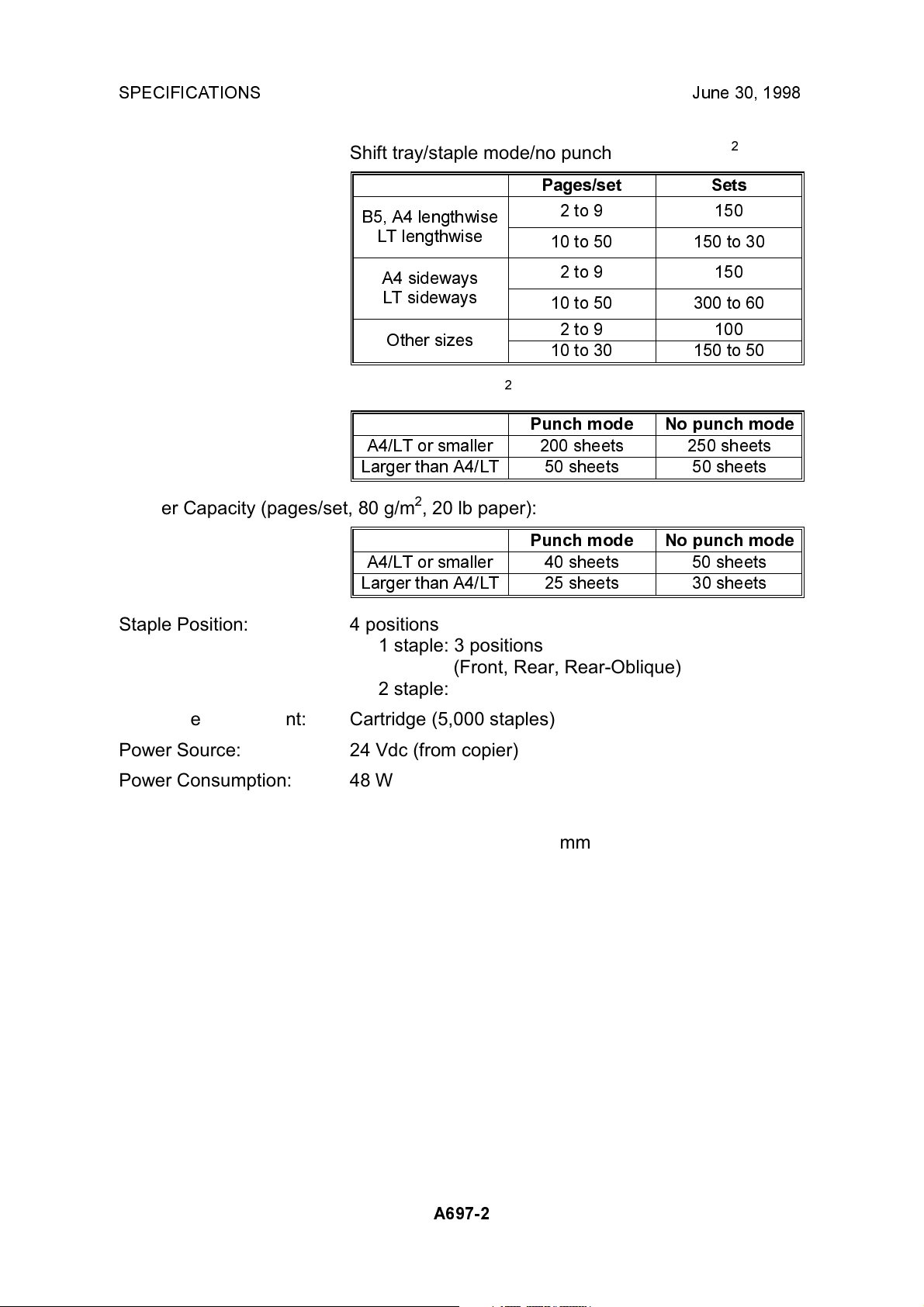
Shift tray/staple mode/no punch mode (80 g/m2, 20 lb):
Pages/set Sets
B5, A4 lengthwise
LT lengthwise
2 to 9 150
10 to 50 150 to 30
A4 sideways
LT sideways
Other sizes
Upper tray (80 g/m2, 20 lb):
Punch mode No punch mode
A4/LT or smaller 200 sheets 250 sheets
Larger than A4/LT 50 sheets 50 sheets
Stapler Capacity (pages/set, 80 g/m2, 20 lb paper):
Punch mode No punch mode
A4/LT or smaller 40 sheets 50 sheets
Larger than A4/LT 25 sheets 30 sheets
Staple Position: 4 positions
1 staple: 3 positions
(Front, Rear, Rear-Oblique)
2 staple: 1 position
Staple Replenishment: Cartridge (5,000 staples)
2 to 9 150
10 to 50 300 to 60
2 to 9 100
10 to 30 150 to 50
Power Source: 24 Vdc (from copier)
Power Consumption: 48 W
Weight: 45 kg
Size (W x D x H): 625 mm x 545 mm x 960 mm
A697-2
Page 4
June 30, 1998 MECHANICAL COMPONENT LAYOUT
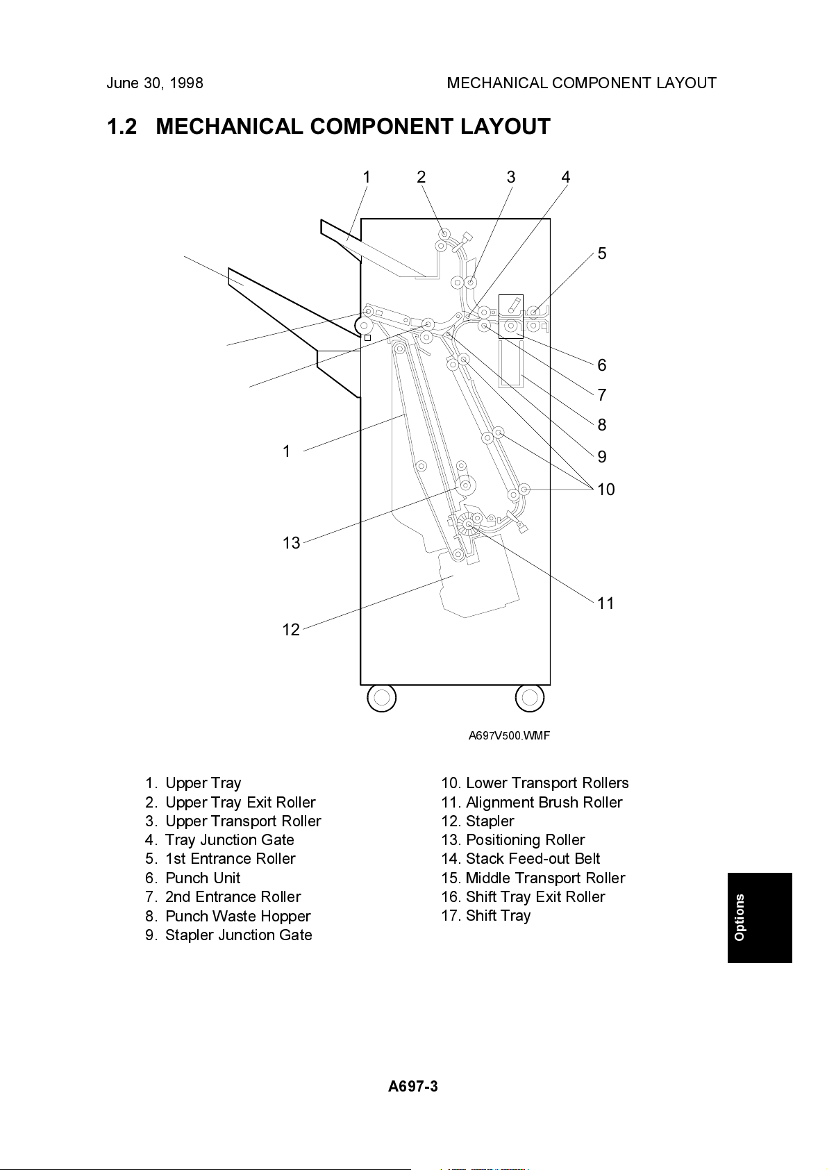
1.2 MECHANICAL COMPONENT LAYOUT
17
16
15
14
13
1
2 3 4
5
6
7
8
9
10
12
1. Upper Tray
2. Upper Tray Exit Roller
3. Upper Transport Roller
4. Tray Junction Gate
5. 1st Entrance Roller
6. Punch Unit
7. 2nd Entrance Roller
8. Punch Waste Hopper
9. Stapler Junction Gate
11
A697V500.WMF
10. Lower Transport Rollers
11. Alignment Brush Roller
12. Stapler
13. Positioning Roller
14. Stack Feed-out Belt
15. Middle Transport Roller
16. Shift Tray Exit Roller
17. Shift Tray
Options
A697-3
Page 5
ELECTRICAL COMPONENT LAYOUT June 30, 1998
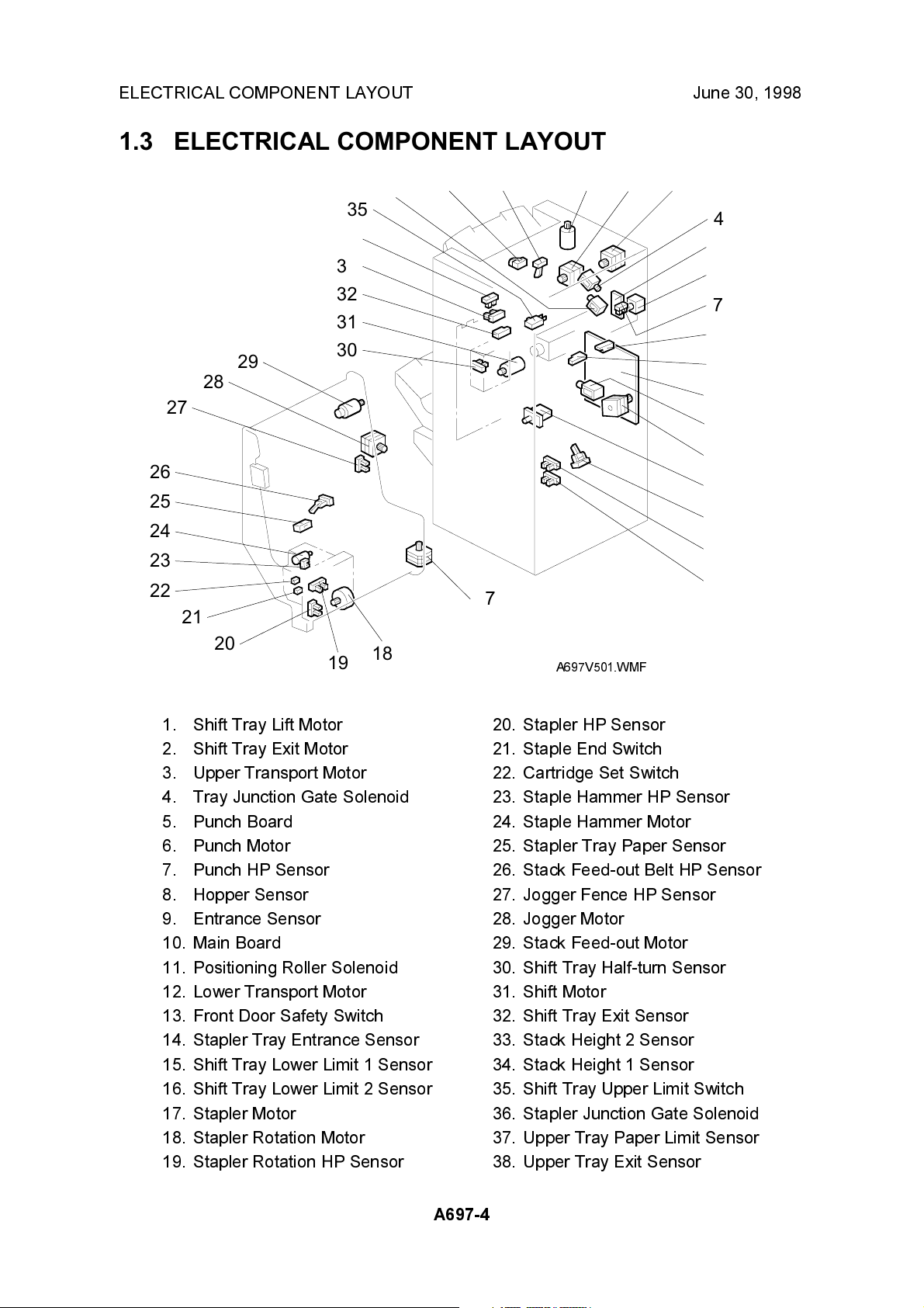
1.3 ELECTRICAL COMPONENT LAYOUT
26
25
24
23
22
27
21
28
29
34
33
32
31
30
35
36
37 38 1 2 3
4
5
6
7
8
9
10
11
12
13
14
15
16
17
20
1. Shift Tray Lift Motor
2. Shift Tray Exit Motor
3. Upper Transport Motor
4. Tray Junction Gate Solenoid
5. Punch Board
6. Punch Motor
7. Punch HP Sensor
8. Hopper Sensor
9. Entrance Sensor
10. Main Board
11. Positioning Roller Solenoid
12. Lower Transport Motor
13. Front Door Safety Switch
14. Stapler Tray Entrance Sensor
15. Shift Tray Lower Limit 1 Sensor
16. Shift Tray Lower Limit 2 Sensor
17. Stapler Motor
18. Stapler Rotation Motor
19. Stapler Rotation HP Sensor
19
18
A697V501.WMF
20. Stapler HP Sensor
21. Staple End Switch
22. Cartridge Set Switch
23. Staple Hammer HP Sensor
24. Staple Hammer Motor
25. Stapler Tray Paper Sensor
26. Stack Feed-out Belt HP Sensor
27. Jogger Fence HP Sensor
28. Jogger Motor
29. Stack Feed-out Motor
30. Shift Tray Half-turn Sensor
31. Shift Motor
32. Shift Tray Exit Sensor
33. Stack Height 2 Sensor
34. Stack Height 1 Sensor
35. Shift Tray Upper Limit Switch
36. Stapler Junction Gate Solenoid
37. Upper Tray Paper Limit Sensor
38. Upper Tray Exit Sensor
A697-4
Page 6
June 30, 1998 ELECTRICAL COMPONENT DESCRIPTION
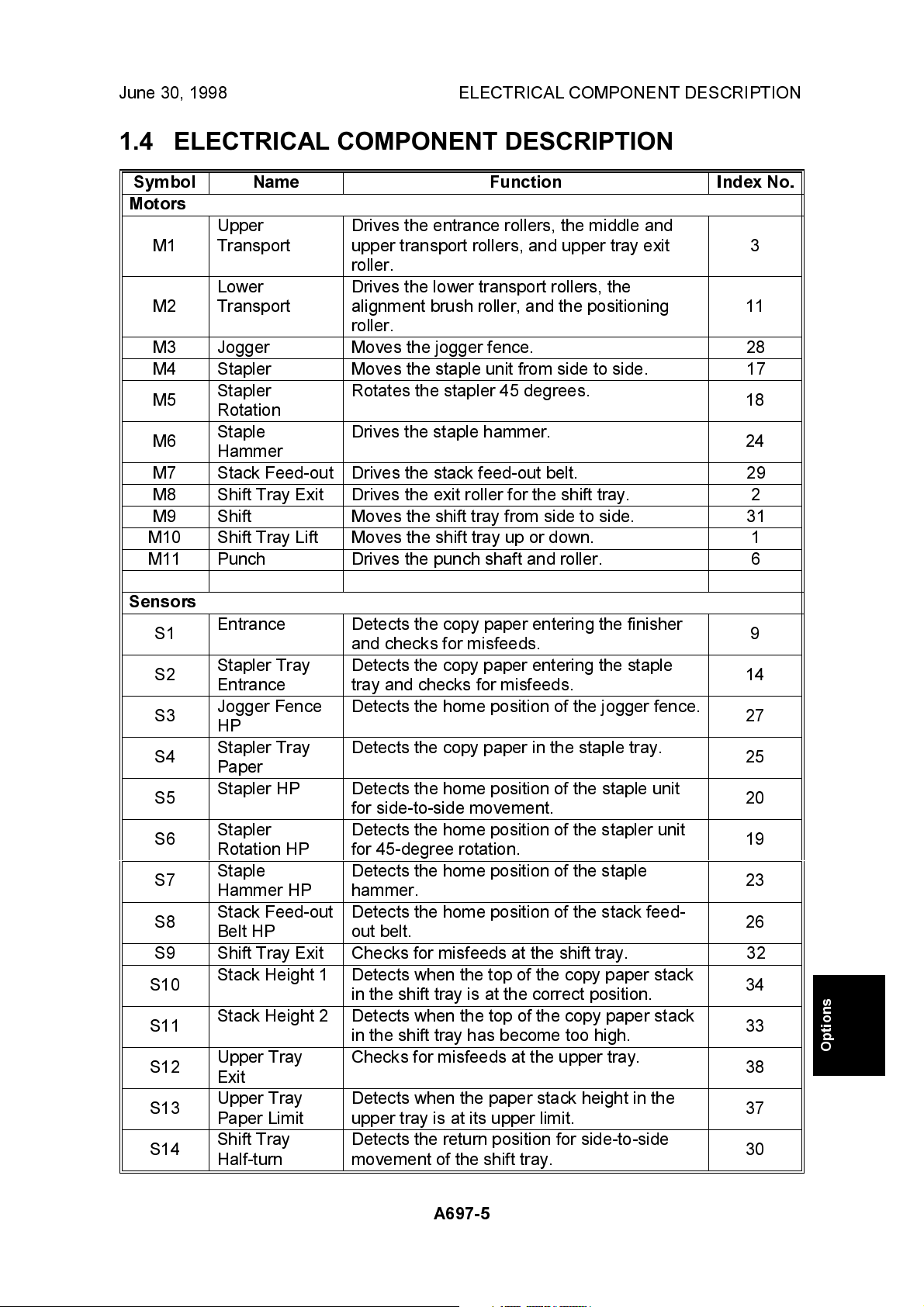
1.4 ELECTRICAL COMPONENT DESCRIPTION
Symbol Name Function Index No.
Motors
Upper
M1
M2
M3 Jogger Mo ves the jogger fence. 28
M4 Stapler Moves the staple unit from side to side. 17
M5
M6
M7 Stack Feed-out Drives the stack feed-out belt. 29
M8 Shift Tray Exit Drives the exit roller for the shift tray. 2
M9 Shift Mo ves the shift tray from side to side. 31
M10 Shift Tray Lift Moves the shift tray up or down. 1
M11 Punch Drives the punch shaft and roller. 6
Transport
Lower
Transport
Stapler
Rotation
Staple
Hammer
Drives the entrance rollers, the middle and
upper transport rollers, and upper tray exit
roller.
Drives the lower transport rollers, the
alignment brush roller, and the positioning
roller.
Rotates the stapler 45 degrees.
Drives the staple hammer.
3
11
18
24
Sensors
S1
S2
S3
S4
S5
S6
S7
S8
S9 Shift Tray Exit Checks for misfeeds at the shift tray. 32
S10
S11
S12
S13
S14
Entrance Detects the copy paper entering the finisher
and checks for misfeeds.
Stapler Tray
Entrance
Jogger FenceHPDetects the home position of the jogger fence.
Stapler Tray
Paper
Stapler HP Detects the home position of the staple unit
Stapler
Rotation HP
Staple
Hammer HP
Stack Feed-out
Belt HP
Stack Height 1
Stack Height 2 Detects when the top of the copy paper stack
Upper Tray
Exit
Upper Tray
Paper Limit
Shift Tray
Half-turn
Detects the copy paper entering the staple
tray and checks for misfeeds.
Detects the copy paper in the staple tray.
for side-to-side movement.
Detects the home position of the stapler unit
for 45-degree rotation.
Detects the home position of the staple
hammer.
Detects the home position of the stack feed-
out belt.
Detects when the top of the copy paper stack
in the shift tray is at the correct position.
in the shift tray has become too high.
Checks for misfeeds at the upper tray.
Detects when the paper stack height in the
upper tray is at its upper limit.
Detects the return position for side-to-side
movement of the shift tray.
9
14
27
25
20
19
23
26
34
33
Options
38
37
30
A697-5
Page 7
ELECTRICAL COMPONENT DESCRIPTION June 30, 1998
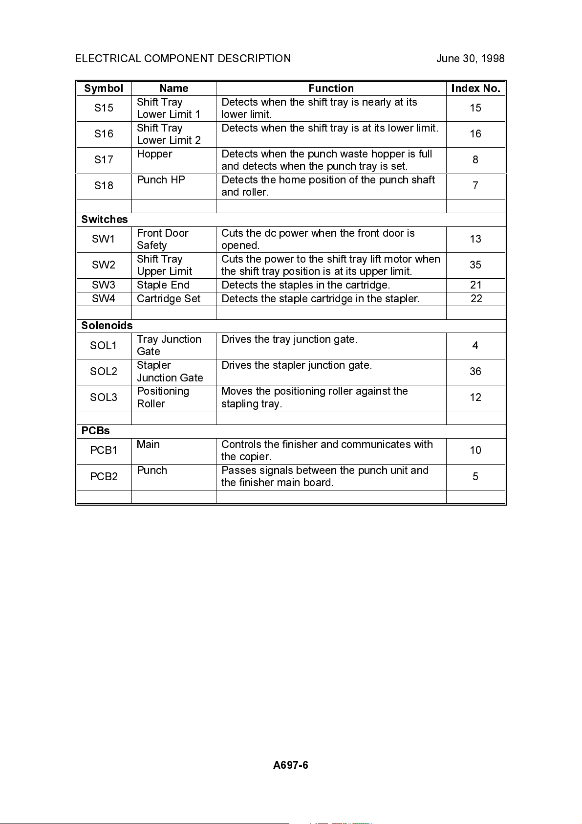
Symbol Name Function Index No.
S15
S16
S17
S18
Shift Tray
Lower Limit 1
Shift Tray
Lower Limit 2
Hopper Detects when the punch waste hopper is full
Punch HP Detects the home position of the punch shaft
Detects when the shift tray is nearly at its
lower limit.
Detects when the shift tray is at its lower limit.
and detects when the punch tray is set.
and roller.
15
16
8
7
Switches
SW1
SW2
Front Door
Safety
Shift Tray
Upper Limit
Cuts the dc power when the front door is
opened.
Cuts the power to the shift tray lift motor when
the shift tray position is at its upper limit.
13
35
SW3 Staple End Detects the staples in the cartridge. 21
SW4 Cartridge Set Detects the staple cartridge in the stapler. 22
Solenoids
SOL1
SOL2
SOL3
Tray Junction
Gate
Stapler
Junction Gate
Positioning
Roller
Drives the tray junction gate.
Drives the stapler junction gate.
Moves the positioning roller against the
stapling tray.
4
36
12
PCBs
PCB1
PCB2
Main Controls the finisher and communicates with
the copier.
Punch
Passes signals between the punch unit and
the finisher main board.
10
5
A697-6
Page 8
June 30, 1998 DRIVE LAYOUT
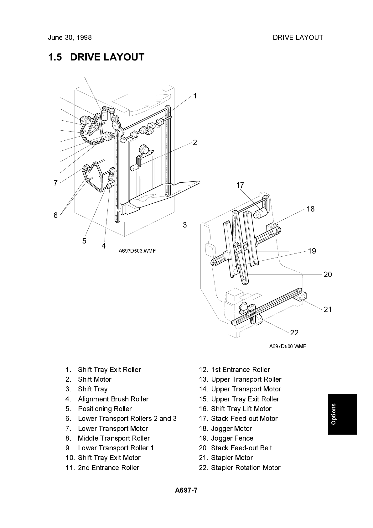
1.5 DRIVE LAYOUT
16
15
14
13
12
11
10
9
8
7
6
1
2
17
18
3
5
4
A697D503.WMF
19
20
1. Shift Tray Exit Roller
2. Shift Motor
3. Shift Tray
4. Alignment Brush Roller
5. Positioning Roller
6. Lower Transport Rollers 2 and 3
7. Lower Transport Motor
8. Middle Transport Roller
9. Lower Transport Roller 1
10. Shift Tray Exit Motor
11. 2nd Entrance Roller
A697-7
A697D500.WMF
12. 1st Entrance Roller
13. Upper Transport Roller
14. Upper Transport Motor
15. Upper Tray Exit Roller
16. Shift Tray Lift Motor
17. Stack Feed-out Motor
18. Jogger Motor
19. Jogger Fence
20. Stack Feed-out Belt
21. Stapler Motor
22. Stapler Rotation Motor
21
22
Options
Page 9
TRAY AND STAPLER JUNCTION GATE MECHANISM June 30, 1998
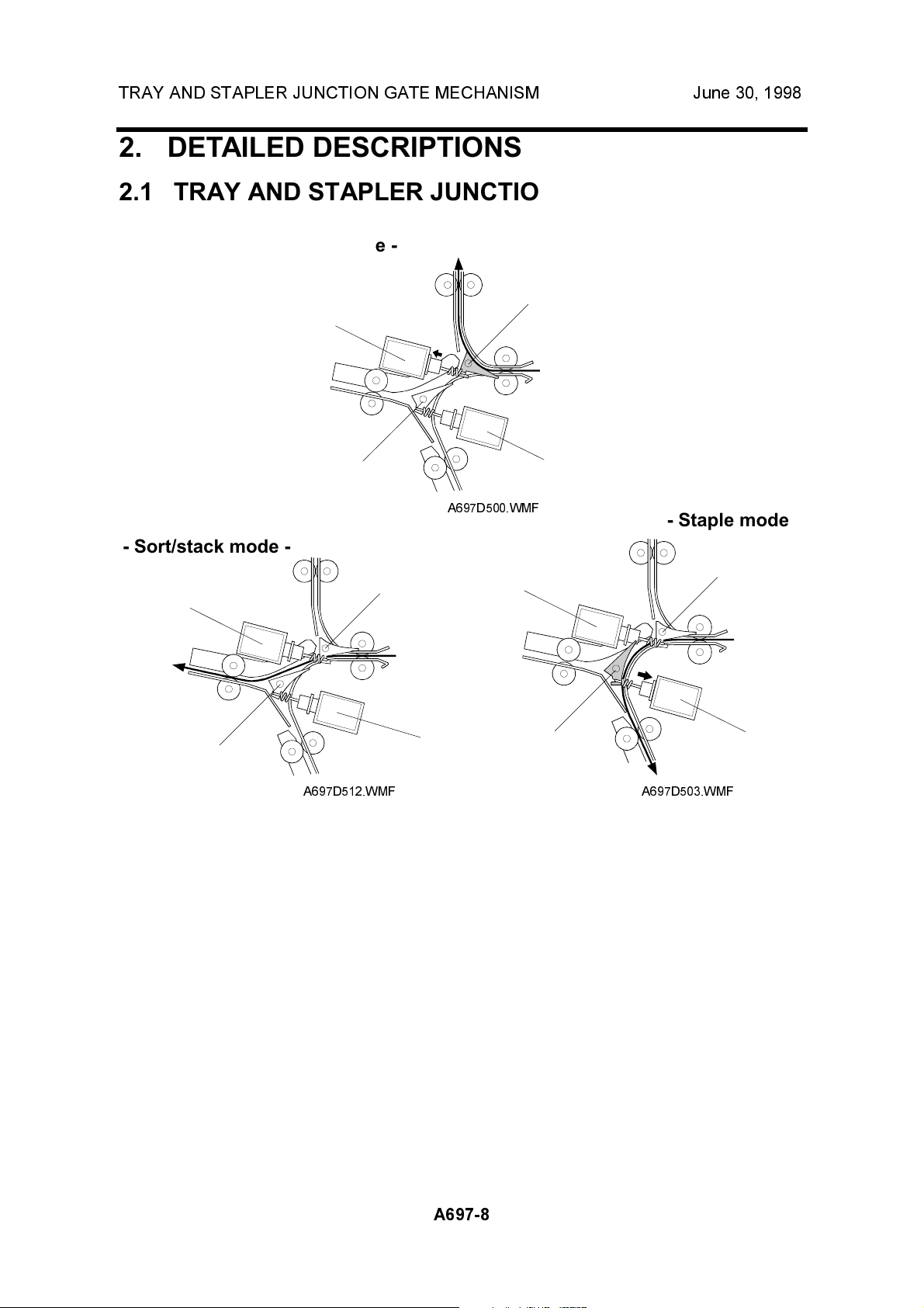
2. DETAILED DESCRIPTIONS
2.1 TRAY AND STAPLER JUNCTION GATE MECHANISM
- Upper tray mode -
[A]
[C]
[B]
A697D500.WMF
[D]
- Staple mode -
- Sort/stack mode -
[A]
[A]
[C]
[C]
[B]
A697D512.WMF
[D]
[B]
A697D503.WMF
[D]
Depending on the finishing mode, the copies are directed up, straight through, or
down by the combination of the tray junction gate [A] and stapler junction gate [B].
These gates are controlled by the tray junction gate solenoid [C] and stapler
junction gate solenoid [D].
Upper tray mode
The tray junction gate solenoid turns on. The copies go up to the upper tray.
Sort/stack mode
The tray junction gate solenoid and the stapler junction gate solenoid remain off.
The copies are sent to the shift tray directly.
Staple mode
The tray junction gate solenoid remains off and the stapler junction gate solenoid
turns on. The copies go downwards to the jogger unit.
A697-8
Page 10
June 30, 1998 JOGGER UNIT PAPER POSITIONING MECHANISM
2.2 JOGGER UNIT PAPER POSITIONING MECHANISM
[C]
[F]
[G]
[A]
[D]
[E]
[B]
[D]
[C]
[A]
A697D504.WMF
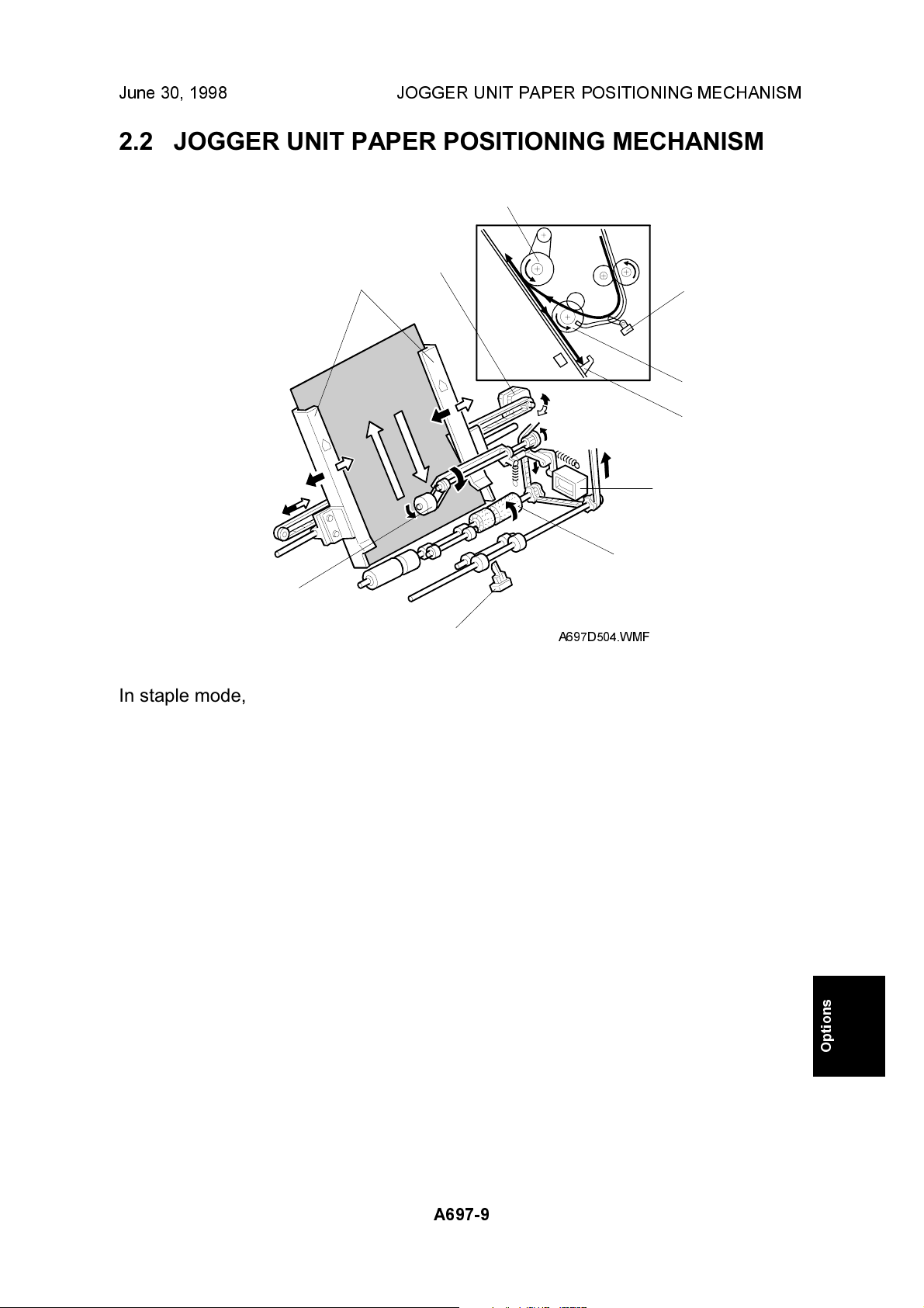
In staple mode, each sheet of copy paper is vertically and horizontally aligned
when it arrives in the jogger unit.
Vertical Paper Alignment
After the trailing edge of the copy passes the stapler tray entrance sensor [A], the
positioning roller solenoid [B] is energized for 280 ms to push the positioning roller
[C] into contact with the paper. The positioning roller and alignment brush roller [D]
rotate to push the paper back and align the trailing edge of the paper against the
stack stopper [E].
Horizontal Paper Alignment
When the print key is pressed, the jogger motor [F] turns on and the jogger fences
[G] move to the waiting position, which is 7 mm wider on both sides than the
selected paper.
When the trailing edge of the paper passes the staple unit entrance sensor, the
jogger motor turns on for approximately 70 ms to move the jogger fences 5 mm
towards the paper. After a short time, the jogger motor turns on again
approximately for 60 ms for the horizontal paper alignment then goes back to the
waiting position.
A697-9
Options
Page 11
STAPLER UNIT MOVEMENT MECHANISM June 30, 1998
2.3 STAPLER UNIT MOVEMENT MECHANISM
[A]
[B]
[C]
A697D505.WMF
A697D506.WMF
[B]
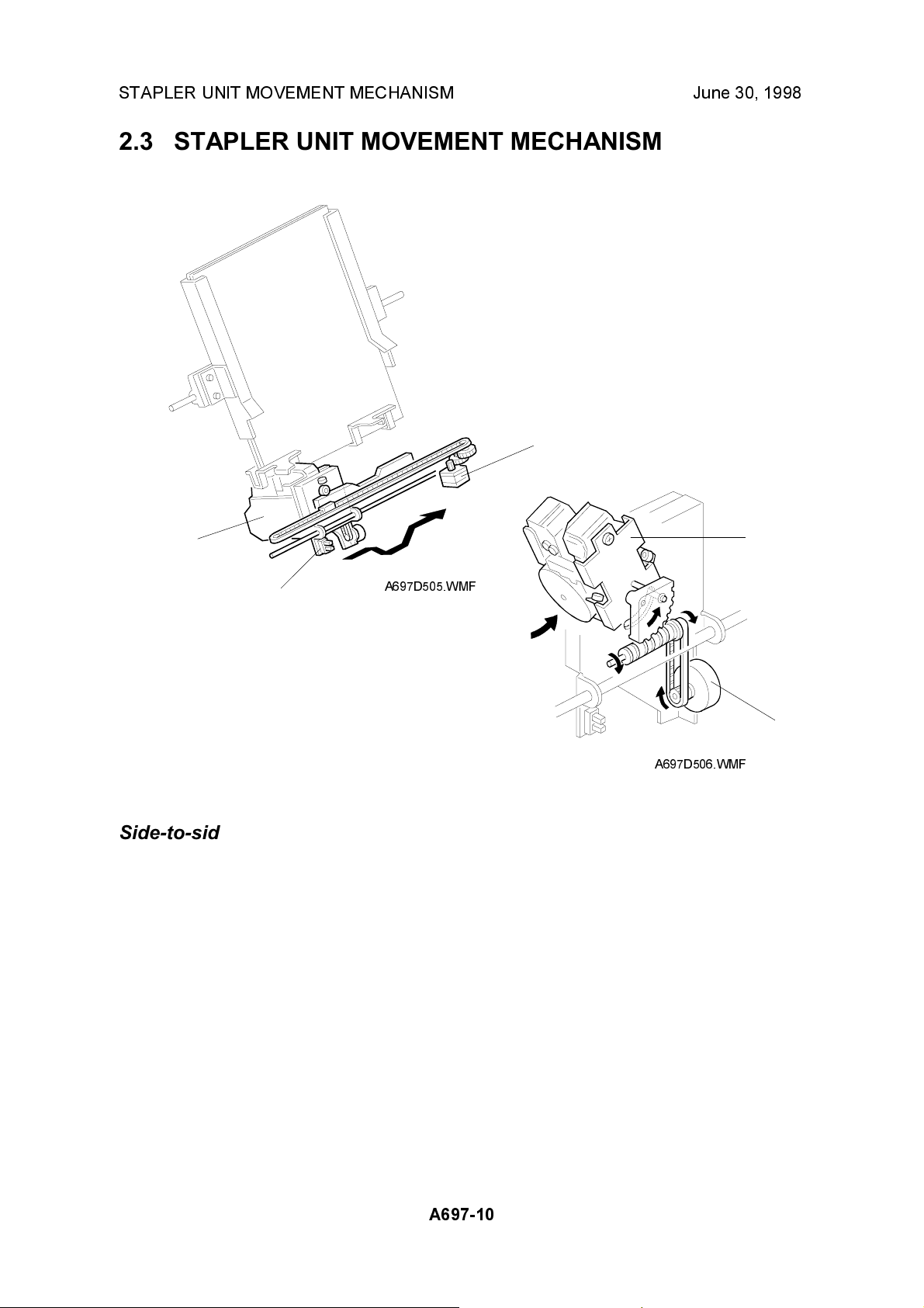
Side-to-side:
The stapler motor [A] moves the stapler [B] from side to side. After the start key is
pressed, the stapler moves from its home position to the stapling position.
If two-staple-position mode is selected, the stapler moves to the front stapling
position first, then moves to the rear stapling position. However, for the next copy
set, it staples in the reverse order (at the rear side first then at the front side).
After the job is completed, the stapler moves back to its home position. This is
detected by the stapler HP sensor [C].
[D]
Rotation:
In the oblique staple position mode, the stapler rotation motor [D] rotates the
stapler 45° after it moves to the stapling position.
A697-10
Page 12

June 30, 1998 STAPLER
2.4 STAPLER
[A]
[E]
[B]
[C]
[F]
A697507.WMF
[D]
[G]
[H]
[I]
A697D508.WMF
The staple hammer [A] is driven by the staple hammer motor [B] via gears [C], two
cams [D], and two links [E].
When the aligned copies are brought to the stapling position by the positioning
roller, alignment brush roller and jogger fences, the staple hammer motor starts.
When the cams complete one rotation, the staple hammer home position sensor
[F] turns on, detecting the end of the stapling operation. The staple hammer motor
then stops.
There are two sensors in the stapler. One is the staple end switch [G] for detecting
staple end conditions (it detects when there is only one sheet of staples left in the
cartridge). The other is the cartridge set switch [H] for detecting whether a staple
cartridge is installed.
When a staple end or no cartridge condition is detected, a message is displayed
advising the operator to install a staple cartridge. If this condition is detected during
a copy job, the indication will appear, but the copy job will not stop.
The staple cartridge has a clinch area [I], in which jammed staples are left.
Operators can remove the jammed staples from this area.
Options
A697-11
Page 13

FEED-OUT MECHANISM June 30, 1998
2.5 FEED-OUT MECHANISM
[E]
[D]
[A]
[B]
[F]
[B]
[C]
A697D509.WMF
After the copies have been stapled, the stack feed-out motor [A] starts. The pawl
[B] on the stack feed-out belt [C] transports the set of stapled copies up and feeds
it to the exit roller [D]. The shift tray exit roller [D] takes over the stack feed-out after
the leading edge reaches this roller.
Just before the stapled copies pass through the shift tray exit sensor, the stackfeed-out motor turns off 600 ms to wait until the exit rollers have completely fed the
stapled stack out to the shift tray [E]. Then, the stack-feed-out motor turns on again
until the pawl actuates the stack feed-out belt home position sensor [F].
A697-12
Page 14

June 30, 1998 SHIFT TRAY UP/DOWN MECHANISM
2.6 SHIFT TRAY UP/DOWN MECHANISM
[D]
[F]
[E]
[A]
[K]
[J]
[I]
[G]
[H]
A697D510.WMF
[B]
[C]
The shift tray lift motor [A] controls the vertical position of the shift tray [B] through
gears and timing belts [C]. When the main switch is turned on, the tray is initialized
at the upper position. The tray is moved up until stack height sensor 1 [D] is deactuated.
During copying, the actuator feeler [E] gradually rises as the copy stack grows, and
the actuator gradually moves towards stack height sensor 2 [F].
In sort/stack mode, if stack height sensor 2 is actuated for 3 seconds, the shift tray
lift motor lowers the shift tray for 15 ms.
In staple mode, when the stack feed-out motor starts, the tray is moved down until
stack height sensor 1 is actuated and then moved up until stack height sensor 1 is
de-actuated. This corrects the current tray position. Then, the tray is moved down
again until stack height sensor 1 is actuated to make space for the coming set of
copies and then moved up until stack height sensor 1 is de-actuated. This means
the tray lowers earlier in staple mode, to prevent the next copy suddenly exceeding
the space currently available on the tray.
For both modes, the shift tray will rise until stack height sensor 1 is de-actuated
when the user takes the stack of paper from the shift tray.
This machine has two shift tray lower limit sensors 1 [G], 2 [H]. Shift tray lower limit
sensor 1 detects the near lower limit and sensor 2 detects the lower limit. When the
actuator [I] enters sensor 1, a message will be displayed and copying will continue.
When the actuator enters sensor 2, a message will be displayed and copying will
stop.
Options
The shift tray upper limit switch [J] prevents the drive gear from being damaged if
stack height sensor 1 fails. When the shift tray pushes up the shift tray positioning
roller [K], the switch will cut the power to the shift tray lift motor.
A697-13
Page 15

SHIFT TRAY SIDE-TO-SIDE MECHANISM June 30, 1998
2.7 SHIFT TRAY SIDE-TO-SIDE MECHANISM
[A]
[D]
[C]
[F]
[E]
[B]
A697D511.WMF
In sort/stack mode, the shift tray [A] moves from side to side to separate the sets of
copies.
The horizontal position of the shift tray is controlled by the shift motor [B] and shift
gear disk [C]. After one set of copies is made and delivered to the shift tray, the
shift motor turns on, driving the shift gear disk and the shaft [D]. The end fence [E]
is positioned by the shaft, creating the side-to-side movement.
When the shift gear disk has rotated 180 degrees (when the shift tray is fully shifted
across), the cut-out in the shift gear disk turns on the shift tray half-turn sensor [F]
and the shift motor stops. The next set of copies is then delivered. The motor turns
on, repeating the same process and moving the tray back to the previous position.
A697-14
Page 16

June 30, 1998 PUNCH UNIT DRIVE MECHANISM
2.8 PUNCH UNIT DRIVE MECHANISM
[C]
[D]
[B]
[A]
A697D501.WMF
The punch unit makes 2 or 3 holes (depending on the type of punch unit) at the
trailing edge of the paper.
The punch unit is driven by the punch motor [A]. The punch motor turns on 78 ms
after the trailing edge of the paper passes through the entrance sensor [B], and
makes the punch holes.
The home position is detected by the punch HP sensor [C]. When the cut-out on
the punch shaft gear disk [D] enters the punch HP sensor, the punch motor stops.
The punch position is adjusted as follows:
Right to left: SP mode
Front to rear: Spacers
A697-15
Options
Page 17

PUNCH WASTE COLLECTION MECHNISM June 30, 1998
2.9 PUNCH WASTE COLLECTION MECHNISM
[B]
[D]
[C]
[A]
A697D502.WMF
The punch waste is collected in the punch waste hopper [A], which is under the
punch unit.
When the punch waste covers the hole [B] in the hopper, the hopper sensor [C]
turns on and a message will be displayed after the copy job finishes.
The hopper sensor also works as the hopper set sensor. If the punch waste hopper
is not set, the hopper sensor moves away from the hole in the hopper holder [D]
and a message is displayed. This message is the same as for the hopper full
condition.
A697-16
Page 18

June 30, 1998 JAM CONDITIONS
2.10 JAM CONDITIONS
1. The entrance sensor does not turn on within 450 ms after the copier exit sensor
turns off.
2. The entrance sensor does not turn off within 1,325 ms after it turns on.
3. The upper tray exit sensor does not turn on within 1,630 ms after the entrance
sensor turns on.
4. The upper tray exit sensor does not turn off within 1,325 ms after it turns on.
5. In sort/stack mode, the shift tray exit sensor does not turn on within 2,090 ms
after the entrance sensor turns on.
6. In sort/stack mode, the shift tray exit sensor does not turn off within 1,325 ms
after it turns on.
7. In staple mode, the stapler tray entrance sensor does not turn on within 3,700
ms after the entrance sensor turns on.
8. In staple mode, the stapler tray entrance sensor does not turn off within 1,325
ms after it turns on.
9. In staple mode, the stapler tray paper sensor does not turn off within 250
pulses of the stack feed-out motor after it starts.
10. In staple mode, the shift tray exit sensor does not turn off within 1,260 ms after
the stack feed-out motor starts.
A697-17
Options
Page 19

TIMING CHARTS June 30, 1998
2.11 TIMING CHARTS
2.11.1 A4 SIDEWAYS (2 SHEETS): NORMAL AND PUNCH MODE
Copier > Finisher
Motor On
(Exit Sensor On)
Motor On
Motor Off
Finisher > Copier
Exit
Finisher
Entrance Sensor
Punch HP Sensor
Shift Tray Exit Sensor
Punch Motor
Upper Transport Motor
Punch Motor
Tray Junction Gate
Solenoid
(Exit Sensor On)
78ms
A697D513.WMF
A697-18
Page 20

June 30, 1998 TIMING CHARTS
2.11.2 A4 SIDEWAYS (2 SHEETS): SORT/STACK AND PUNCH
MODE
Copier > Finisher
Motor On
(Exit Sensor On)
Motor On
Motor Off
Finisher > Copier
Exit
Finisher
Entrance Sensor
Punch HP Sensor
Shift Tray Exit Sensor
Shift Tray Half Turn
Upper Transport Motor
Shift Tray Exit Motor
Punch Motor
Shift Motor
(Exit Sensor On)
78ms
A697D514.WMF
A697-19
Options
Page 21

TIMING CHARTS June 30, 1998
2.11.3 A4 SIDEWAYS (2 SHEETS): STAPLE AND PUNCH MODE
Copier > Finisher
(Exit Sensor On)
Motor On
Stapler On
Motor Off
Finisher > Copier
Exit
Staple Count
Finisher
Entrance Sensor
Punch HP Sensor
Stapler Entrance Sensor
Stapler Tray Paper Sensor
Shift Tray Exit Sensor
Upper Transport Motor
Lower Transport Motor
Punch Motor
Jogger Motor
Stapler Motor
Jogger Fence HP Sensor
Stapler HP Sensor
Stapler Junction Gate
Solenoid
Positioning Roller Solenoid
Staple Hammer Motor
Staple Hammer HP Sensor
Stack Feed-out Motor
Stack Feed-out Belt HP
Sensor
Shift Tray Exit Motor
70ms
40ms
100ms
A697D515.WMF
A697-20
Page 22

June 30, 1998 DIP SWITCHES
3. SERVICE TABLES
3.1 DIP SWITCHES
DPS100 DPS101
12341234
00000000Default
11011000Stack feed-out motor on
11100100Free run: sort/stack mode
11100010Free run: one staple (front side)
11100001Free run: two staples
NOTE:
Do not use any other settings.
Description
3.2 TEST POINTS
No. Label Monitored Signal
TP101 (GND) Ground
3.3 LED
No. Function
LED100 Monitors the stack feed-out motor speed.
3.4 VARIABLE RESISTORS
No. Function
VR100 Adjust the stack feed-out motor speed.
3.5 FUSES
No. Function
FU100 Protects 24 V.
Options
A697-21
Page 23

COVER REPLACEMENT June 30, 1998
4. REPLACEMENT AND ADJUSTMENT
4.1 COVER REPLACEMENT
[B]
[D]
[E]
[F]
Rear Cover
1. Remove the rear cover [A] (3 screws).
Upper Left Cover
[C]
A697R500.WMF
[A]
1. Remove the upper left cover [B] (2 screws).
Upper Cover
1. Remove the upper left cover.
2. Remove the upper cover [C] (2 screws).
Front Door
1. Remove the upper left cover.
2. Remove the upper cover.
3. Remove the upper bracket [D] (1 screw).
4. Remove the front door [E].
Left Front Cover
1. Remove the rear cover.
2. Remove the upper cover.
3. Remove the front door.
4. Remove the left front cover [F] (2 screws).
A697-22
Page 24

June 30, 1998 COVER REPLACEMENT
[G]
[I]
[B]
[E]
[J]
[F]
[C]
[D]
A697R500.WMF
[A]
[H]
Shift Tray
1. Remove the rear cover [A].
2. Rotate the shift tray lift motor and lower the shift tray [B].
3. Remove the shift tray (4 screws).
Lower Left Cover
1. Remove the shift tray.
2. Remove the upper left cover [C].
3. Remove the upper cover [D].
4. Remove the front door [E].
5. Remove the left front cover [F].
6. Remove the lower left cover [G] (4 screws).
Right Cover
1. Remove the right cover [H] (2 screws).
Front Shift Tray Cover
1. Remove the front shift tray cover [I] (1 screw).
Options
Rear Shift Tray Cover
1. Remove the rear shift tray cover [J] (1 screw).
A697-23
Page 25

POSITIONING ROLLER REPLACEMENT June 30, 1998
4.2 POSITIONING ROLLER REPLACEMENT
[B]
[C]
1. Open the front door.
2. Remove the snap ring [A].
3. Release the rubber belt [B].
4. Replace the positioning roller [C].
[A]
A697R501.WMF
A697-24
Page 26

June 30, 1998 ALIGNMENT BRUSH ROLLER REPLACEMENT
4.3 ALIGNMENT BRUSH ROLLER REPLACEMENT
[D]
[B]
[E]
[C]
[F]
[A]
[H]
[G]
A697R502.WMF
1. Open the front door and pull out the jogger unit.
2. Remove the rear cover.
3. Remove the main board [A] (6 screws, all connectors).
4. Remove a screw [B] and a tension spring [C] for the tension bracket [D], and
release the tension of the timing belt.
5. Remove the front side E-ring [E] and bushing [F].
6. Remove the alignment brush roller assembly.
7. Remove the timing pulley [G] (1 E-ring).
8. Replace the alignment brush roller [H] (1 spacer, 1 bushing).
A697-25
Options
Page 27

SENSOR REPLACEMNT June 30, 1998
4.4 SENSOR REPLACEMNT
4.4.1 STACK HEIGHT SENSOR 1 AND 2
[A]
[B]
[D]
[C]
1. Remove the upper left cover.
2. Remove the upper cover.
3. Remove the sensor feeler [A] (1 screw, 1 connector).
4. Remove the sensor bracket [B] (1 screw).
5. Replace the stack height sensor 1 [C] or 2 [D].
A697R503.WMF
A697-26
Page 28

June 30, 1998 SENSOR REPLACEMNT
4.4.2 UPPER TRAY PAPER LIMIT AND EXIT SENSOR
[C]
[D]
[B]
[A]
A697R504.WMF
1. Remove the upper left cover.
2. Remove the upper cover.
Upper Tray Paper Limit Sensor
3. Remove the sensor bracket [A] (1 screw).
4. Replace the upper tray paper limit sensor [B] (1 connector).
Upper Tray Exit Sensor
3. Remove the sensor bracket [C] (1 screw).
4. Replace the upper tray exit sensor [D] (1 connector).
A697-27
Options
Page 29

SENSOR REPLACEMNT June 30, 1998
A
4.4.3 SHIFT TRAY EXIT SENSOR
[A]
[D]
[B]
697R505.WMF
[C]
A697R506.WMF
1. Remove the rear cover.
2. Remove the upper left cover.
3. Remove the upper cover.
4. Open the front door and remove the upper exit guide [A] (1 plastic clip).
5. Remove the guide stay [B] (2 screws).
6. Remove the discharge brush [C] (2 screws).
7. Replace the shift tray exit sensor [D] (1 screw, 1 connector).
A697-28
Page 30

June 30, 1998 SENSOR REPLACEMNT
4.4.4 ENTRANCE AND STAPLER TRAY ENTRANCE SENSOR
[B]
[A]
[D]
[C]
A697R507.WMF
1. Remove the finisher from the copier.
Entrance Sensor
2. Remove the sensor bracket [A] (1 screw).
3. Replace the entrance sensor [B] (1 screw, 1 connector).
Stapler Tray Entrance Sensor
2. Remove the sensor bracket [C] (1 screw).
3. Replace the stapler tray entrance sensor [D] (1 screw, 1 connector).
Options
A697-29
Page 31

SENSOR REPLACEMNT June 30, 1998
4.4.5 STAPLER ROTATION HP SENSOR
[B]
[A]
[D]
[C]
A697R510.WMF
1. Remove the stapler unit.
2. Remove the screw [A] and rotate the stapler bracket [B].
3. Remove the sensor bracket [C] (1 screw).
4. Replace the stapler rotation HP sensor [D] (1 connector).
A697-30
Page 32

June 30, 1998 STAPLER REMOVAL
4.5 STAPLER REMOVAL
[A]
1. Open the front door and pull out the jogger unit.
2. Move the stapler to the front.
3. Remove the stapler [A] (1 screw, 1 connector).
A697R509.WMF
A697-31
Options
Page 33

PUNCH POSITION ADJUSTMENT June 30, 1998
4.6 PUNCH POSITION ADJUSTMENT
A697R508.WMF
Right to left
This position is adjusted by SP modes.
Front to rear
The optional punch units have the following 3 spacers as accessories.
1 mm thickness: 2 pcs
2 mm thickness: 1 pc
The punch position can be adjusted by up to 4 mm by combinations of the 3
spacers.
A697-32
Page 34

June 30, 1998 STACK FEED-OUT MOTOR SPEED ADJUSTMENT
4.7 STACK FEED-OUT MOTOR SPEED ADJUSTMENT
NOTE:
This adjustment is required after replacing the main board.
1. Set the DIP switches on the finisher main board as follows.
DIP SW 1 2 3 4
DIP100 On On Off On
DIP101 On Off Off Off
2. If LED100 remains lit, turn VR100 counterclockwise until LED100 starts
blinking.
3. Turn VR100 clockwise until the LED stops blinking and remains lit.
A697-33
Options
Page 35

3,000-SHEET FINISHER (A697) ELECTRICAL COMPONENT LAYOUT
26
25
24
23
22
27
21
28
29
34
33
32
31
30
35
36
37 38 1 2 3
4
5
6
7
8
9
10
11
12
13
14
15
16
17
20
Index
Symbol
Motors
M1 3 Upper Transport B13
M2 11 Lower Transport C13
M3 28 Jogger L13
M4 17 Stapler N13
M5 18 Stapler Rotation O13
M6 24 Staple Hammer Q13
M7 29 Stack Feed-out H13
M8 2 Shift Tray Exit G13
M9 31 Shift I13
M10 1 Shift Tray Lift E13
M11 6 Punch S2
Sensors
S1 9 Entrance E2
S2 14 Stapler Tray Entrance F2
S3 27 Jogger Fence HP N2
S4 25 Stapler Tray Paper N2
S5 20 Stapler HP O2
S6 19 Stapler Rotation HP P2
S7 23 Staple Hammer HP R13
S8 26 Stack Feed-out Belt HP M2
S9 32 Shift Tray Exit H2
S10 34 Stack Height 1 I2
S11 33 Stack Height 2 J2
S12 38 Upper Tray Exit F2
S13 37 Upper Tray Ppaer Limit G2
S14 30 Shift Tray Half-turn L2
S15 15 Shift Tray Lower Limit 1 J2
S16 16 Shift Tray Lower Limit 2 K2
S17 8 Hopper R2
S18 7 Punch HP Q2
No.
Description P to P
19
18
Index
Symbol
Switches
SW1 13 Front Door Safety D2
SW2 35 Shift Tray Upper Limit J13
SW3 21 Staple End R13
SW4 22 Cartridge Set Q13
Solenoids
SOL1 4 Tray Junction Gate E13
SOL2 36 Stapler Junction Gate J13
SOL3 12 Positioning Roller K13
PCBs
PCB1 10 Main T6
PCB2 5 Punch Q4
No.
Description P to P
Page 36

1234567891011121314
POINT TO POINT DIAGRAM (FINISHER 3,000: A697)
A
Copier
B
C
Front Door
D
Safety Switch
Entrance
E
Sensor
Stapler Tray
Entrance
Sensor
F
Upper Tray
Exit Sensor
Upper Tray
G
Paper Limit
Sensor
H
Shift Tray
Exit Sensor
Paper Height 1
I
Sensor
Paper Height 2
Sensor
J
Shift Tray
Lower Limit 1
Sensor
K
Shift Tray
Lower Limit 2
Sensor
Shift Tray
L
Half-turn
Sensor
Stack Feed-
out Belt HP
M
Sensor
Jogger Fence
HP Sensor
N
Stapler Tray
Paper Sensor
O
Stapler HP
Sensor
Stapler Rotation
P
HP Sensor
Punch HP
Sensor
Q
Hopper
Sensor
R
Punch
Motor
S
S1
S2
S12
S13
S9
S11
S10
S15
S16
S14
S8
S3
S4
S5
S6
S18
S17
M11
SW1
CN650
CN254-1
CN204-1
CN205-1
-1
-2
-3
-1
-2
-3
-1
-2
-3
-1
-2
-3
CN267-1
CN257-1
-1
-2
-3
CN268-1
CN258-1
CN208-1
CN259-1
-1
-2
-3
CN620
-6
-1
-5
-2
-4
-3
CN620CN630
-1 -3
-2
-2
-1
-3
CN610-1
-2
-3
-2
-3
-2
-3
-2
-3
-2
-3
-2
-3
-2
-3
-2
-3
-2
-3
-2
-4
-5
-6
-7
CN266
CN256
CN206
CN206
CN207
CN209
Punch
Board
(PCB2)
CN101-1
CN102-2
CN103-1
CN104-6
CN104-3
CN105-3
-1
-2
-3
-1
-2
-3
-1
-2
-3
-4
-5
-6
-1
-2
-3
-1
-2
-3
CN106CN366
CN106CN356
CN106CN316
CN106CN306
CN107-9
CN107-6
CN107CN307
CN108-9
CN108-6
CN108-3
CN109-6
CN109CN309
-1
-2
-3
-4
-5
-6
-7
-8
-9
-10
-11
[24] 24V
-2
[24] 24V
-3
[24] 24V
-4
[0] GND1
-5
[0] GND1
-6
[0] GND1
[0] GND2
-3
RXD
-4
[0] GND2
-5
TXD
[24] 24V
-2
[s24] Front Door Safety Switch
A
[0] GND2
-5
[t5] Entrance Sensor
-4
[5] 5V
[5] 5V
-2
[t5] Stapler Tray Entrance Sensor
-1
[0] GND2
[5] 5V
-2
[0] GND2
-1
[t5] Upper Tray Exit Sensor
-13
[0] GND2
-12
[t5] Upper Tray Paper Limit Sensor
-11
[5] 5V
-10
[0] GND2
-9
[t5] Shift Tray Exit Sensor
-8
[5] 5V
-6
[5] 5V
-5
[0] GND2
-4
[s5] Paper Height 1 Sensor
-3
[5] 5V
-2
[0] GND2
-1
[s5] Paper Height 2 Sensor
[5] 5V
-8
[s5] Shift Tray Lower Limit 1 Sensor
-7
[0] GND2
[5] 5V
-5
[s5] Shift Tray Lower Limit 2 Sensor
-4
[0] GND2
-3
[5] 5V
-2
[s5] Shift Tray Half-turn Sensor
-1
[0] GND2
[5] 5V
-8
[0] GND2
-7
[s5] Stack Feed-out Belt HP Sensor
[5] 5V
-5
[s5] Jogger Fence HP Sensor
-4
[0] GND2
[0] GND2
-2
[s5] Stapler Tray HP Sensor
-1
[5] 5V
[5] 5V
-5
[s5] Stapler HP Sensor
-4
[0] GND2
-3
[5] 5V
-2
[s5] Stapler Rotation HP Sensor
-1
[0] GND2
CN121CN600
-11
[s5] Hopper Sensor
-10
[t5] Punch Unit Installed
-9
[s5] Punch HP Sensor
-8
[t24 0/24 ] Punch Motor B
-7
[t24 0/24 ] Punch Motor A
-6
[t24 0/24 ] Punch Motor B
-5
[t24 0/24 ] Punch Motor A
-4
[0] GND2
-3
[5] 5V
-2
[0] GND1
-1
[24] 24V
A
Main Board
(PCB1)
T
A
Upper Transport Motor:A[t24 0/24 ]
Upper Transport Motor:A[t24 0/24 ]
Upper Transport Motor:B[t24 0/24 ]
Upper Transport Motor:B[t24 0/24 ]
A
Lower Transport Motor:A[t24 0/24 ]
Lower Transport Motor:A[t24 0/24 ]
Lower Transport Motor:B[t24 0/24 ]
Lower Transport Motor:B[t24 0/24 ]
A
Shift Tray Lift Motor:+[t24]
Shift Tray Lift Motor:-[t24]
Tray Junction Gate Sol. [t24]
A
Shift Tray Exit Motor:A[t24 0/24 ]
Shift Tray Exit Motor:A[t24 0/24 ]
Exit Motor:B[t24 0/24 ]
Exit Motor:B[t24 0/24 ]
A
Stapler Rotation Motor:A[t24 0/24 ]
Stapler Rotation Motor:A[t24 0/24 ]
Stapler Rotation Motor:B[t24 0/24 ]
Stapler Rotation Motor:B[t24 0/24 ]
A
Stack Feed-out Motor:+[t24]
Stack Feed-out Motor:-[t24]
Stack Feed-out Motor F.S. [0/12]
Stack Feed-out Motor F.S. [0/12]
Shift Tray Upper Limit Switch [s24]
Stapler Junction Gate Sol. [t24]
Positioning Roller Sol. [t24]
A
Jogger Motor:A[t24 0/24 ]
Jogger Motor:A[t24 0/24 ]
Jogger Motor:B[t24 0/24 ]
Jogger Motor:B[t24 0/24 ]
A
Stapler Motor:A[t24 0/24 ]
Stapler Motor:A[t24 0/24 ]
Stapler Motor:B[t24 0/24 ]
Stapler Motor:B[t24 0/24 ]
A
Staple Hummer Motor:+[t24]
Staple Hummer Motor:+[t24]
Staple Hummer Motor:-[t24]
Staple Hummer Motor:-[t24]
Cartridge Set Switch [s5]
Staple End Switch [t5]
Staple Hammer Sensor [s5]
Stapler Installed [t5]
24V(A) [24]
24V(B) [24]
24V(A) [24]
24V(B) [24]
A
Shift Motor [t24]
A
A
A
24V [24]
24V(A) [24]
24V(B) [24]
24V [24]
24V [24]
24V [24]
24V [24]
24V(A) [24]
24V(B) [24]
24V(A) [24]
24V(B) [24]
24V(A) [24]
24V(B) [24]
GND2 [0]
CN110-1
CN111-1
CN112-1-2CN212-2
CN112-4-5CN222-2
CN113-1 CN213-7
CN114-1
CN115 CN315
-1
-2
CN115-3-4CN215-2
CN116-1
CN117-1
CN118-1 CN218-7
CN118-8 CN228-7
CN119-1 CN219-7
CN120-12 CN220-1
5V [5]
CN210-7
-2
-4
-5
-6
-7
CN211-7
-2
-4
-5
-6
-7
-2
-4
-5
-6
-7
CN214-5
-2
-4
-5
CN215
-4
-3
-2
-2
-2
-4
-5
-6
-7
-9
-11
-12
-13
-14
-2
-4
-5
-6
-7
-11
-9
-8
-6
-5
-4
3
-2 -11
-1
-10
-12
A
-6
-4
-3
-2
-1
-6
-4
-3
-2
-1
-1
-1
-6
-4
-3
-2
-1
-4
-2
-1
-2
-1
M1
M2
M10
SOL
1
M8
M7
M9
SW2
-1
SOL
2
SOL
3
-6
-4
-3
-2
-1
-6
-4
-3
-2
-1
-6
-4
-3
-2
-1
-2
-4
-5
-7
-8
-9
M3
M4
M5
M6
SW4
SW3
S7
Upper
Transport
Motor
Lower
Transport
Motor
Shift Tray
Lift Motor
Tray Junction
Gate Solenoid
Shift Tray
Exit Motor
Stack
Feed-out
Motor
Shift
Motor
Shift Tray
Upper Limit
Switch
Stapler
Junction Gate
Solenoid
Positioning
Roller
Solenoid
Jogger
Motor
Stapler
Motor
Stapler
Rotation
Motor
Stapler
B
C
D
E
F
G
H
I
J
K
L
M
N
O
P
Q
R
SYMBOL TABLE
DC Line
Pulse Signal
S
Signal Direction
Active High
s
Active Low
t
Voltage
[]
T
1234567891011121314
 Loading...