

Page 1

FINISHER
Click here for information on differences
between the SR700 and the SR710
(Machine Code: A612)
Page 2

22 March 1996 OVERALL MACHINE INFORMATION
1. OVERALL MACHINE INFORMATION
1.1 SPECIFICATIONS
Paper Size: Standard copyin g/ St ack mode
Maximum: 11" x 17" /A3
Minimum: 51/2" x 81/2"/A5
Staple mode
Maximum: 11" x 17" /A3
Minimum: 8" x 11"/B5
Paper Weight: Standard copyin g/ St ack mode
14 ~ 42 lb/52 ~ 157 g/m
Staple mode
17 ~ 21 lb/64 ~ 80 g/ m
Paper Capacity: 1,500 sheets:
81/2" x 11"/A4 or smaller size (20 lb/80 g/m2)
1,000 sheets:
81/2" x 14"/B4 or larger size (20 lb/80 g/m2)
2
2
Stapler Capacity: 81/2" x 11"/A4 or smaller size (20 lb/80 g/m2):
from 2 to 50 sheets
81/2" x 14"/B4 or large size (20 lb/80 g/m2):
from 2 to 30 sheets
Staple Replenishmen t: Cartridge exchange (5, 000 staples/cartridge)
Power Source: DC 24 V (from copier)
Power Consumption: 48 W (average)
Weight: 35 kg (77.2 lb)
Finisher
1
Page 3
a
OVERALL MACHINE INFORMATION 22 March 1996
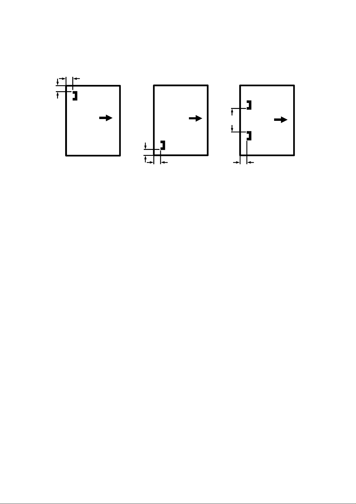
Stapling Position:
- 1 staple - - 2 staples -
b
b
b
aa
A612V500.wmf
a = 0.24" ± 0.12" (6 ± 3 mm)
b = 0.24" ± 0.12" (6 ± 3 mm)
a = 0.24" ± 0.12" (6 ± 3 mm)
b = 0.24" ± 0.12" (6 ± 3 mm)
Dimensions: 26.5" x 20.5" x 37.5"
(671 mm x 514 mm x 950 mm)
a = 0.24" ± 0.12" (6 ± 3 mm)
b = 5.20" ± 0.12" (132 ± 3 mm)
2
Page 4
12
11910
22 March 1996 OVERALL MACHINE INFORMATION
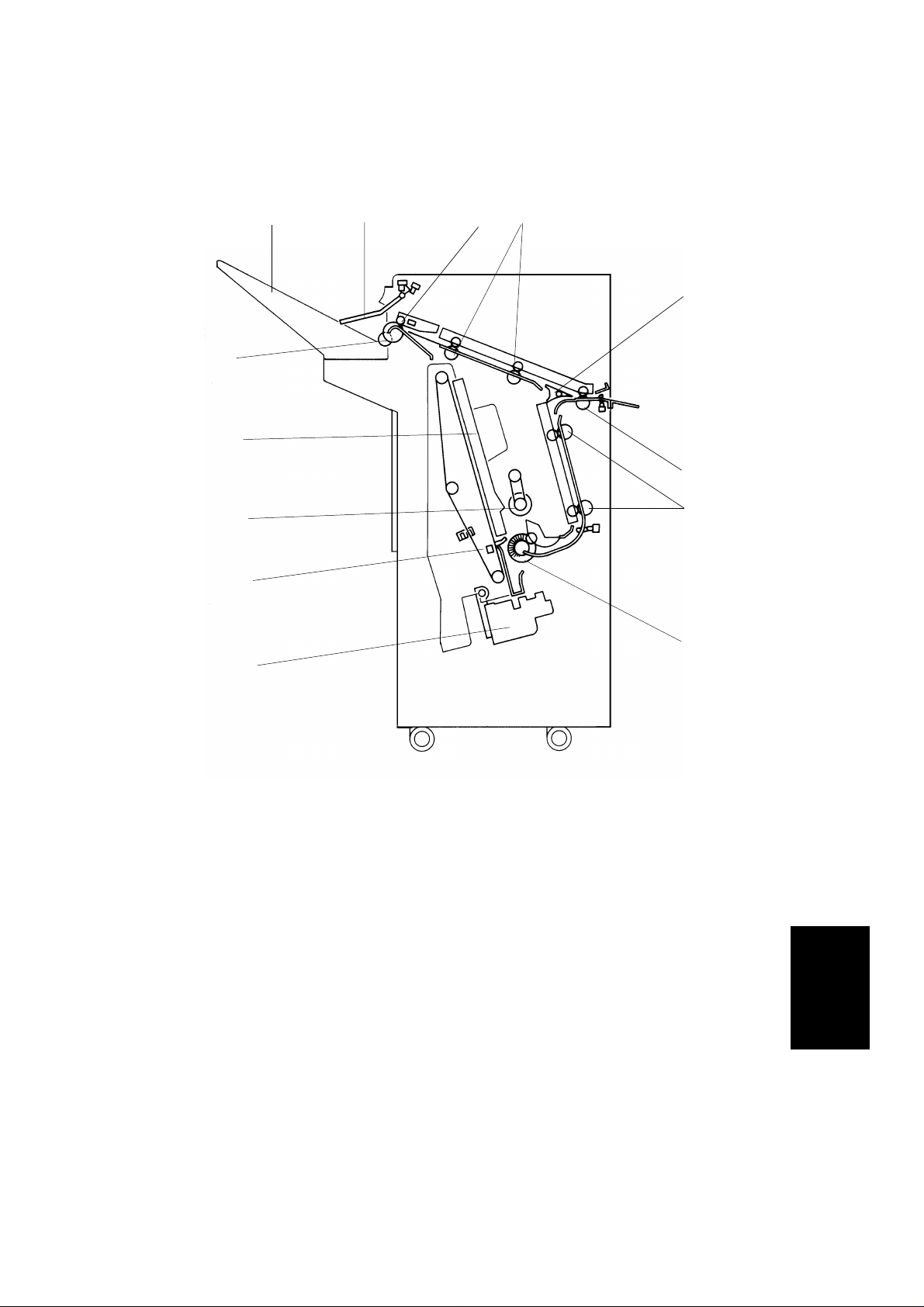
1.2 MECHANICAL COMPONENT LAYOUT
2
1
13
3
4
5
6
8
7
1. Stack Height Sensor Feeler
2. Shift Tray
3. Shift Tray Positioning Roller
4. Jogger Unit
5. Positioning Roller
6. Stack Feed-out Belt
7. Stapler Unit
A612V501.img
8. Alignment Brush Roller
9. Lower Transport Rollers
10. Entrance Rollers
11. Junction Gate
12. Upper Transport Rollers
13. Exit Rollers
Finisher
3
Page 5

OVERALL MACHINE INFORMATION 22 March 1996
1.3 ELECTRICAL COMPONENT DES CRIPTI O N
Refer to the electrical compo nent layou t on the reverse side of the
point-to-poin t dia gram (on waterproof paper) for the index numbe rs.
Symbol Name Function
Motors
M1 Transport Drive Drives the transport rollers. 21
M2 Shift Tray Lift Moves the shift tray up or down. 25
M3 Exit Drive Drives the exit roller and the shift tray
positioning roller.
M4 Stack Feed-out Drives the stack feed-out belt. 5
M5 Jogger Moves the jogger fences. 19
M6 Stapler Drive Moves the stapler unit. 17
M7 Shift Moves the shift tray from side to side. 7
M8 Staple Drives the staple hammer. 13
M9 Lower Transport Drive Drives the transport rollers of the stapler
section.
Sensors
S1 Entrance Detects copy paper entering the finisher. 26
S2 Jogger Unit Entrance Detects copy paper entering the jogger
unit.
S3 Jogger Unit Paper Detects copy paper in the jogger unit. 8
S4 Stack Feed-out Belt HP Detects the home position of the stack
feed-out belt.
S5 Jogger HP Detects the jogger home position. 18
S6 Exit Detects misfeeds in the exit area. 3
S7 Stack Height 1 Detects copy paper stack height in
staple mode.
S8 Stack Height 2 Detects copy paper stack height in
sort/stack mode.
S9 Shift Tray Lower Limit Detects the lower limit of the shift tray
position.
S10 Staple Hammer HP Detects the staple hammer home
position.
S11 Shift Tray Half-Turn Detects the side-to-side position of the
shift tray.
S12 Stapler Unit HP Detects the stapler unit home position. 10
Index
No.
27
22
24
9
2
1
15
14
6
4
Page 6

22 March 1996 OVERALL MACHINE INFORMATION
Symbol Name Function
Switches
SW1 Front Door Safety Cuts the dc power when the front door is
opened.
SW2 Shift Tray Upper Limit Cuts the power to the shift tray lift motor
when the shift tray position is at its upper
limit.
SW3 Cartridge Set Detects whether a staple cartridge is
installed.
SW4 Staple End Detects staples in the cartridge. 11
Solenoids
SOL1 Positioning Roller Lowers the positioning roller in the
jogger unit.
SOL2 Junction Gate Drives the junction gate. 23
PCBs
PCB1 Main Control Controls overall finisher operation. 16
Index
No.
28
4
12
20
Finisher
5
Page 7
5
1
OVERALL MACHINE INFORMATION 22 March 1996
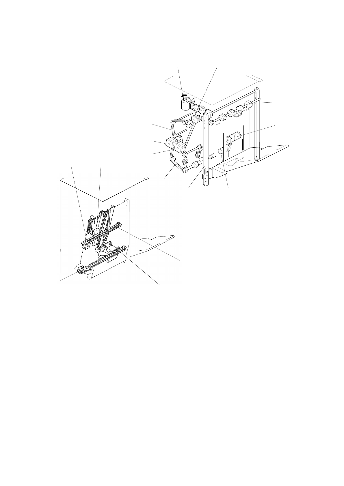
1.4 DRIVE LAYOUT
10
2
13
12
11
9
8
7
6
14
A612V502.img
16
15
3
4
A612V503.wmf
1. Exit Drive Motor (M3)
2. Exit Roller
3. Shift Cam
4. Shift Motor (M7)
5. Shift Tray Lift Belt
6. Lower Transport Drive Belt
7. Transport Drive Motor (M1)
8. Lower Transport Drive Motor
9. Upper Transport Drive Belt
10. Shift Tray Lift Motor (M2)
11. Stack Feed-out Moto r (M4 )
12. Jogger Motor (M5)
13. Stapler Drive Motor (M6)
14. Stapler Drive Belt
15. Jogger Drive Belt
16. Stack Feed-out Belt
(M9)
6
Page 8
[A]
[E]
22 March 1996 OVERALL MACHINE INFORMATION
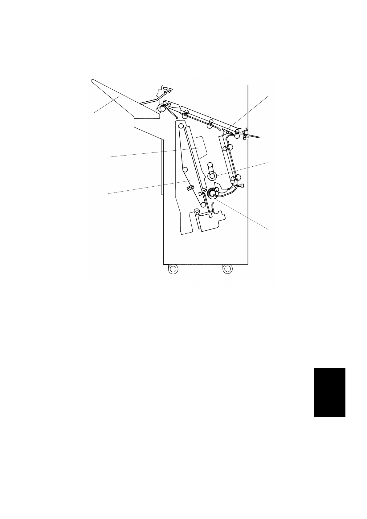
1.5 BASIC OPERATI ON
[B]
[F]
[D]
[C]
A612V501-2.img
The finisher recognizes the base copier type by receivin g the copier’s paper
exit speed data when the main switch is turn ed on. The pa per transport
speed depends on the base copier.
After the copy is completed, the paper is directed to the finisher. If the
sort/stack mode is selecte d, the junction gate [A] dire cts the paper upwards
to send it to the shift tray [B]. In these modes, th e shif t tra y is shifte d fro m
side to side to stagge r and sepa rat e set s of cop ies. The amount of shift is
approximately 30 mm.
When the staple mode is selected, th e jun ctio n gate direct s the paper
downwards to send it to the jogger un it [C] . Ea ch time a copy is delive red to
the jogger unit, the position ing roller [D], the alignment brush ro ller [E ], and
the jogger fences [F ] squ are the stack of copies. After the final copy of the set
is squared, the set is stap led , an d th en delive red to th e shif t tray.
7
Finisher
Page 9

SECTIONAL DESCRIPTIONS 22 March 1996
2. SECTIONAL DESCRIPTIONS
2.1 PAPER DELIVERY S WITCHI NG
[B]
[A]
[C]
A612D500.img
Depending on the sele cte d finishing mode, the copie s are directed up or
down by the junction gate [A ], which is controlled by a solenoid. This
happens after the ent ran ce sen sor [C] has been activated.
(1) When the exit sensor of the copie r is activat ed while in sta ple mode , th e
solenoid [B] is energ ized . The n, the junction gate directs the copies down
to send them to the jogger unit.
(2) When the exit sensor of the copie r is activat ed while in th e sort /st ack
mode, the solenoid stays off. The junction gat e dire cts th e copies up to
send them to the shif t tra y.
8
Page 10

22 March 1996 SECTIONAL DESCRIPTIONS
2.2 SHIFT TRAY UP/DOWN MECHANI S M
[F]
[B]
[J]
[E]
[D]
[A]
[J]
[H]
[I]
[G]
[C]
A612D502.wmf
The shift tray lift motor (a dc mot or) [B ] con tro ls the vertica l posit ion of the
shift tray [A] through gears and timing belts [C]. When the main switch is
turned on, the tray is initialized at the upper position. The tray’s upper
position is detecte d whe n th e shift tray pushes up actuat or [D] unt il the
actuator has just left the stack height sensor 1 [E], and is now between the
two sensors [E] and [F] .
During copying, the actuator feeler gradually rises as the copy stack grows,
and the actuator gradu ally move s towa rds sta ck heig ht sensor 2. In sort/stack
mode, if the actuator remains inside stack height sensor 2 [F] for 4 s, the shift
tray lift motor lowers the tray unit for 50 ms. In staple mode, if th e act uato r
leaves stack height sen sor 1 fo r 4 s during a copy run , th e mot or lowe rs t he
tray until stack height senso r 1 is actua ted. This mean s the tray lowe rs earlie r
in staple mode, to preven t pro ble ms cause d by sud de n arrivals o f sta ple d
stacks of paper on the tray (sta plin g is don e insid e the machine, and the
stapled copy is fed out to th e tra y; the second copy may suddenly exceed the
space currently availab le on the tray).
For both modes, the shift tray will rise when the user takes th e sta ck of pape r
from the tray during cop ying.
When the tray reaches its lower limit, actuat or [H] enters th e lower limit
sensor [G], and cop ying stop s. After copying ends and th e mach ine stop s,
the tray is raised to its uppermost position 4 s after the copies are removed.
The shift tray upper limit switch [I] prevent s the drive gears fro m bein g
damaged if stack heig ht senso r 1 fa ils. When the shift tray pu she s up th e shif t
tray positioning roller [J], the switch cuts the power to the shift tray lift motor.
9
Finisher
Page 11

[E]
SECTIONAL DESCRIPTIONS 22 March 1996
2.3 SHIFT TRAY SIDE-TO-S IDE S HIFT MECHANI S M
[B][C]
[A]
[D]
[F]
[G]
[H]
A162D503.img
In the sort/stack mode, the shift tray [A ] move s from side to side to stagg er
and separate the set s of cop ies.
The horizontal position of the shift tray is controlled by the shift moto r (dc
motor) [B] and the shift cam (helical cam) [C]. After one set of origina ls is
copied and delivered to the shift tray, the shift motor [ B] start s rota tin g, driving
the shift cam through the timin g belt. The pin [D] fixe d to the shift tray base
plate [E] is position ed in the groo ve on the shift cam, creating the side-to-side
movement required to sta gg er th e cop ies.
When the shift cam has rotated 180 degrees (when the tray is fully shifted
across), the plate [F] on the shift cam pushes the actuator [G] of the shift tray
half-turn sensor [H] and the shift motor stops. The next set of copies is then
delivered. The moto r ro ta te s, rep ea ting the same process and moving the
tray back to the previous posit ion .
10
Page 12

[F]
[D]
22 March 1996 SECTIONAL DESCRIPTIONS
2.4 STAPLE UNIT PAPE R PO SITI O NING
[C]
[B]
[D]
[F]
[E]
[A]
[H]
[G]
[C]
A612D504.img
In staple mode, each sheet of cop y paper is vertically and horizontally
aligned when it arrives in the jogger unit.
For horizontal pape r align men t, the jogger motor [A] moves bot h th e front and
the rear jogger fences [B ] to align the copies.
For vertical paper alignment, th e positio nin g roller [C] an d the alignment
brush roller [D] push the copy again st th e stack stopper [E].
After the trailing edge of the copy passes th e jog ger unit entrance sensor [F],
the positioning roller sole no id [G ] is energized for 280 ms to push the
positioning roller int o conta ct with the paper. The positioning roller rotates to
push the paper back and align the trailin g edge of the pape r aga inst the stack
stopper. Both the positioning roller and the alignme nt brush roller are driven
by the lower transport drive motor throu gh the timing belt [H].
11
Finisher
Page 13

[B]
SECTIONAL DESCRIPTIONS 22 March 1996
2.5 JOGGER MOVEMENT
(2)(1) (3)
7 mm 2 mm
[A]
A612D505.wmf
When the Start key is pressed, the copie r sends the paper size inf ormation to
the finisher. In accorda nce with th at dat a, the jogg er mot or (ste pp er mot or)
starts rotating to position the front and rea r jogg er fe nce s [A] 7 mm away from
the selected paper’s edges. (1)
After the trailing edge of the copy passes th e jog ger unit entrance sensor,
each jogger fence moves inward 5 mm. They stop 2 mm away from the paper
edges. (2)
Just after the position ing roller pushes the copy back, each jogger fence
moves inward 2 mm more so that the leaf spring [B] on the rear jogg er fe nce
pushes the copy side ed ge slight ly. (3)
After a copy is stacked in the jogg er tra y, the jogger fences move back 7 mm
from the copy edge for the next copy.
12
Page 14

22 March 1996 SECTIONAL DESCRIPTIONS
2.6 STAPLER
[G]
[H]
[E]
[B]
[A]
[D]
[C]
[F]
A612D507.wmf
[J]
A612D506.wmf
The staple hammer [A] is drive n by th e sta ple r motor [B] via gears [C], two
eccentric cams [D], and two links [E] .
When the aligned copie s are bro ug ht to th e sta pling position by the
positioning roller, alignment brush roller and jogger fences, th e sta ple r moto r
starts. When the cams comp lete one rotation, th e sta ple hamme r h ome
position sensor [F] tu rns on , de te cting the end of the stapling ope rat ion. The
stapler motor then stops.
There are two sensors in the stapler un it. One is the staple end switch [G ] fo r
detecting staple en d con ditions (it detects when there is o nly one sheet of
staples left in the cartridg e). The othe r is the cartridge set switch [H] for
detecting whether a staple cartridge is installed.
When a staple end or no staple cart ridge condition is detecte d, a message is
displayed advising the opera to r to inst all a staple cartridge. If this condition is
detected during a copy job, the indication will appear, but will not stop the
copy job in any way.
Finisher
The staple cartridge has a clinch area [J], in which th e jamme d staples are
left. Operators can remo ve th e jamme d staples from the cartridge.
13
Page 15

SECTIONAL DESCRIPTIONS 22 March 1996
2.7 STAPLER UNIT SIDE-TO- SIDE MOV EME NT
[C]
[B]
[A]
A612D508.wmf
Customers can select one of the following three different staple mod es:
Staple 1: Top left
Staple 2: Bottom left
Staple 3: Top/Bottom left
The stapler drive motor [A ] (a ste pp er mot or) move s the stapler un it [B ] fro m
side to side. After the Start key is pressed, the stapler moves from its home
position to the sta ple posit ion .
If staple mode 3 is selected, the stap ler un it move s to th e fro nt staple po sitio n
first, then moves to the rear staple po sitio n. Howeve r, fo r t he next copy set , it
staples in the reverse ord er; tha t is, at the rear side first an d th en at th e fro nt.
After the job is complet ed , the stapler unit moves back to its ho me position.
(The stapler unit home position sensor [C] is actuated.)
14
Page 16

22 March 1996 SECTIONAL DESCRIPTIONS
2.8 FEED-OUT TO THE SHIFT TRAY
[E]
[A]
[B]
[D]
A612D509.img
[C]
[B]
After the copies ha ve be en stap led, the stack feed-out motor [A] starts. The
pawl [B] on the stack feed -ou t be lt [C] tran sports the set of stapled cop ies up ,
and feeds it to the shift tray. Approximately 0.6 second after the stack
feed-out motor starts, the motor stops for 400 ms. At this moment, the exit
rollers catch the stapled cop ies to feed th em out to the shift tray. Then the
motor rotates again until th e pawl actu at es th e sta ck feed-o ut belt home
position sensor [D].
The exit drive motor starts to drive the exit rollers [E ] whe n the first copy
activates the entrance sen sor. The exit drive mot or spe ed is reduce d just
before each sheet of copy pa pe r is complet ely fed out. This is to ensure an
even copy stack.
Finisher
15
Page 17

INSTALLATION PROCEDURE 22 March 1996
3. INSTALLATION PROCEDURE
[A]
[B]
A612I500.wmf
[C]
[D]
CAUTION
I
Unplug the power cord before begining the follow ing proc edur e.
In European countries only (step 1 ~ 4)
1. Peel off the backin g [A] of the double sided tap e af fixed to the copier
grounding plate [B].
2. Attach the copier grounding plate to the copier as shown.
3. Peel off the backin g [C] of the double sided ta pe aff ixed to the PFU
grounding plate [D].
4. Attach the PFU grounding plate to the paper feed unit as shown.
A612I501.wmf
16
Page 18

22 March 1996 INSTALLATION PROCEDURE
[B]
[A]
[B]
A612I502.wmf
[C]
[D]
[D]
[G]
[F]
[C]
A612I503.wmf
5. Remove the strips of tape [A ] an d the cushoins [B].
6. Open the front door and remove the strips of tap e [C] and cushions [D].
7. Extend the staple unit [F].
8. Remove the strip of tape [G].
Finisher
17
Page 19

INSTALLATION PROCEDURE 22 March 1996
[A]
[A]
[C]
[B]
[E]
A612I508.wmf
[F]
[D]
A612I504.wmf
9. Remove the screws [A] from th e lef t cove r.
10. Install the fro nt conn ect ing bracke t [B] (2 screws– M4 x 12) and the rear
connecting bracket [C] (2 screws– M4 x 12).
11. Affix the mylar strip [D] to the copy exit area, as shown .
NOTE: Carefully align the edge of the cover [E ] with the myla r gude.
12. Affix the cushion [F] to th e lower exit plate, as shown.
18
Page 20

[A]
[J]
22 March 1996 INSTALLATION PROCEDURE
[G]
[E]
[C]
[F]
[D]
[B]
A612I505.wmf
[K]
[L]
[K]
[H]
[I]
A612I506.wmf
13. Open the front door of the finisher and remove the screw [A], which
secures the locking lever [B]. Then pull the locking lever (This causes the
lever to move out and down).
14. Affix the cushion [C] on th e met al stay (not on the cover) as shown.
15. Install the entrance guid e pla te [D] (2 screws -M4 x 6).
16. Open the two clamps; remove the cable [E] and the fiber optic cable [F].
17. Remove the rear cover [G] (6 screws).
18. Align and install the finisher to the connecting brackets. Lock them in
place by raising the locking lever [H].
Finisher
NOTE: Ensure the mylar strip [I] is located betwee n the guides [J].
19. Secure the locking leve r [H] (1 screw) an d th e fin ishe r (2 screws [K] ).
20. Install the shift tra y [L] (4 screws – M4 x 8).
19
Page 21

INSTALLATION PROCEDURE 22 March 1996
[B]
[A]
A612I507.wmf
19. Reinstall the rear cover.
20. Connect the cable [A] and the fiber optic connector [B].
21. Plug in the copier.
22. Turn on the main switch and test the newly inst alle d finisher’s operation.
NOTE: The copier automatically re cog nize s tha t th e fin ishe r has be en
installed. The stapler will begin stap ling after ab ou t 10 copie s
(This allows the first staple to come to the pro pe r posit ion in the
cartridge).
20
Page 22

22 March 1996 SERVICE TABLES
4. SERVICE TABLES
4.1 TEST POINT TABLE (MAIN BOARD)
Number Function
TP100 GND
TP101 5 V
TP102 24 V
4.2 FUSE TABLE
Number Rated Current Location
Fuse 100 5A Main PCB
4.3 LED TABLE
LED No. ON Status During Adjustment
LED100 Stack feed-out motor speed is normal.
*NOTE:Adjust the speed of the stack fe ed -ou t mot or by setting DIP SW
100/101 to Moto r Test Mod e (see belo w). The n ad just VR10 0. If
the motor speed is either too high or too low, LED 100 will blink.
4.4 DIP SW TABLE
4.4.1 Factory Setting
DIP SW100 DIP SW101
12341234
00000000
4.4.2 Motor Test Mode
DIP SW100 DIP SW101
12341234
11011000
Stack Feed-out Motor
After setting DIP SW10 0, turn on switch 1 of DIP SW10 1 to start
the stack feed-out motor. Turn off DIP SW101-1 to sto p th e motor.
Motor
Finisher
21
Page 23

SERVICE TABLES 22 March 1996
4.4.3 Free Run Test Mode Without Paper
DIP SW100 DIP SW101
12341234
11101000
11100100
11100010
11100001
Shift tray mode
Staple mode - Top left
Staple mode - Bottom left
Staple mode -
Test Type
Top/Bott om lef t
Start the free run test mode by chan gin g DIP SW10 0 then DIP SW101
to select the require d te st as shown in the table.
In shift tray mode, the fin ishe r wo rks as if 10 sets of 5 LT pa ges
are being sorted. The mach ine the n initializes itself and repeats the
operation.
In staple mode, th e fin ishe r wo rks as if 5 sets of 5 LT pages are being
stapled and delivered. The machine then initializes itself and rep ea ts th e
operation.
22
Page 24

[E]
[F]
[B]
22 March 1996 REPLACEMENT AND ADJUSTMENT
5. REPLACEMENT AND ADJUSTMENT
5.1 EXTERIOR REMOVAL
[G]
[A]
[C]
[D]
[H]
[I]
[J]
A612R500.img
[I]
1. Remove the left upper cover [A] (2 screws).
2. Remove the upper cover [B] (3 screws).
3. Remove the upper door bra cket [C] (1 screw) and remove the front door
[D].
4. Remove the lower front cover [E ] (2 screws).
5. Remove the front shif t cove r [F] (2 screws).
6. Remove the rear cover [G] (6 screws).
7. Remove the shift tray [H] (4 screws).
NOTE: The shift tray cannot be remove d if it is at its uppe rmost posit ion .
Bring the shift tray down by ma nually turning the shift tray lift
motor timing belt.
8. Remove the fron t and rear tray cover [I] (1 screw at the fro nt, 2 screws at
the rear).
9. Remove the left cover [J] (4 screws).
Finisher
23
Page 25

[I]
REPLACEMENT AND ADJUSTMENT 22 March 1996
5.2 ALIGNMENT BRUSH ROLLER REPLACEMENT
[B]
[D]
[A]
[C]
[H]
[J]
A612R501.wmf
[I]
[H]
[E]
[F]
[G]
[E]
[F]
A612R502.img
1. Open the front door and slid e out the jogger unit .
2. Remove the rear cover.
3. Loosen the screw [A] and flip the tension bracket [B] to release the
tension of the lower t ran spo rt drive belt.
4. Remove the E-ring [C], slide out the pulley [D], remove 2 E-rings [E], then
remove 2 bushings [F].
NOTE: When reinstalling, th e metal bushing goes at the fron t side.
5. Remove the alignmen t bru sh rolle r assemb ly [G] .
6. Remove the 2 E-rings [H] and th e bru sh rolle rs [ I] .
NOTE: Do not lose the link keys [J].
24
Page 26

22 March 1996 REPLACEMENT AND ADJUSTMENT
5.3 STACK HEIGHT SENSOR REPLACE MENT
[E]
[B]
[C]
[D][A]
A612R503.img
1. Remove the upper cover.
2. Remove the stack heigh t sen sor act ua to r [A] (1 screw).
3. Remove the bracket [B ] (1 screw, 2 connect ors).
4. Replace stack height sensor 1 [C] and stack height sensor 2 [D].
NOTE: When reinstalling the bracket [B], align the edge of the bracket
with the stay [E].
Finisher
25
Page 27

REPLACEMENT AND ADJUSTMENT 22 March 1996
5.4 POSITIONING ROLLER REPLACEMENT
[A]
1. Open the front door and slid e out the jogger unit .
2. Remove the position ing roller [A ] (1 sna p ring).
A612R504.img
26
Page 28

[B]
22 March 1996 REPLACEMENT AND ADJUSTMENT
5.5 BELT TENSION ADJUSTMENT
[C]
[A, B]
[a, b]
[C]
[A]
A612R507.wmf
A612R510.wmf
[D]
A612R511.img
1. Remove the rear cover an d adjust the
tension of belt [A] with tightener [a ].
Remove the left upper co ver, the upper
cover, the front door , th e fro nt shift cover and
the lower front cover (2 screws). Ad just the
belt [B] with tighte ne r [b] .
Standard: 6 mm deflection at 50 ± 20 g
pressure.
2. Open the front do or and slide out the jogger
unit. Adjust the te nsio n of belt [C] with
tightener [c].
Finisher
A612R508.wmf
[c]
Standard: 8 mm deflection at 100 ± 30 g
pressure.
27
Page 29

REPLACEMENT AND ADJUSTMENT 22 March 1996
[D]
[d]
150 ± 40 g
A612R509.img
3. Open the front door and slide out the jogge r unit . Ad just the tension of
belt [D] with tightener [d].
Standard: 8 mm deflection at 150 ± 40 g pressure.
28
Page 30

FINISHER (A612) ELECTRICAL COMPONENTS
23
22
21
20
19
18
24
25
26
27
28
1
2
3
4
5
6
7
8
9
10
11
12
17
16
13
14
15
Page 31

Index. No. Index No. Description P to P
1 S8 Stack Height 2 Sensor F2
2 S7 Stack Height 1 Sensor G2
3 S6 Exit Sensor G2
4 SW2 Shift Tray Upper Limit Switch F18
5 M4 Stack Feed-out Motor J16
6 S11 Shift Tray Half Turn Sensor F2
7 M7 Shift Motor E18
8 S3 Jogger Unit Paper Sensor H4
9 S4 Stack Feed-out Belt HP Sensor J4
10 S12 Stapler Unit HP Sensor I4
11 SW4 Staple End Switch L3
12 SW3 Cartridge Set Switch L3
13 M8 Staple Motor K2
14 S10 Staple Hammer HP Sensor L3
15 S9 Shift Tray Lower Limit Sensor E4
16 PCB1 Main Control Board C10
17 M6 Staple Drive Motor H17
18 S5 Jogger HP Sensor I4
19 M5 Jogger Motor I17
20 SOL1 Positioning Roller Solenoid F17
21 M1 Transport Drive Motor C17
22 M9 Lower Transport Drive Motor K17
23 SOL2 Junction Gate Solenoid D17
24 S2 Jogger Unit Entrance Sensor E4
25 M2 Shift Tray Lift Motor D2
26 S1 Entrance Sensor D4
27 M3 Exit Drive Motor G17
28 SW1 Front Door Safety Switch L17
 Loading...